Posted on

Dodge Dakota 1997-2007 Workshop Repair & Service Manual (COMPLETE & INFORMATIVE for DIY REPAIR) ☆ ☆ ☆ ☆ ☆
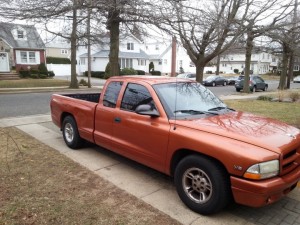
Dodge Dakota 1997-2007 Workshop Repair & Service Manual (COMPLETE & INFORMATIVE for DIY REPAIR)

Dodge Dakota 1997-2007 Workshop Repair & Service Manual (COMPLETE & INFORMATIVE for DIY REPAIR) ☆ ☆ ☆ ☆ ☆

MDGDKT9707OPES.PDF
Price: $19.99 USD

* COMPLETE, Absolutely No Missing Pages!
* Official Service INFORMATION You Can Count On!
* Customer Satisfaction GUARANTEED!

This high QUALITY official manual for Dodge Dakota 1997-2007 is 100 percents COMPLETE and INTACT, no MISSING, CORRUPT pages, sections to freak you out! This manual is exactly as described. It is in the cross-platform PDF document format so that it works like a charm on all kinds of devices.

FORMAT: PDF
LANGUAGE: English
SIZE/PAGE: 627 MB
OS: Windows/Mac OS X/Linux/Android/iOS

INSTANT DELIVERY: A download link will be sent to you instantly after payment. Simply click on the link and save it to your computer. You can use this Manual as long as you wish with no restrictions.

CUSTOMER SATISFACTION: If there is ANY kind of problem with the item you purchased, just drop a quick email. Within HOURS the issue shall be taken care of.

PRINTABLE MANUAL WITH DIAGRAMS: Just print the manual out and start to work. You can also use the manual with your Tablet/Laptop in your garage.

REFUND/EXCHANGE POLICY: We sell high QUALITY products only. However if you encounter any problems with the item you purchased, another replacement link will be sent to you. If we’re at fault, you will get 100 percents refund.

Buy ☆THE BEST MANUAL ON THE INTERNET☆ from responsible seller and get instant download now without uncertainty or surprise.

This highly detailed workshop service repair manual for download contains virtually everything you will ever need to repair, maintain, rebuild, refurbish or restore Dodge Dakota 1997-2007. All diagnostic and repair procedures and gives you access to the same information that professional technicians and mechanics have. You can view and print out the complete repair procedures with this workshop service repair manual Download – you do not need to be skilled with a computer.

EXCERTS:
GROUP TAB LOCATOR
Introduction
0 Lubrication & Maintenance
2 Suspension
3 Differential & Driveline
5 Brakes
6 Clutch
7 Cooling
8A Audio/Video
8B Chime/Buzzer
8E Electronic Control Modules
8F Engine Systems
8G Heated Systems
8H Horn
8I Ignition Control
8J Instrument Cluster
8L Lamps
8M Message Systems
8N Power Systems
😯 Restraints
8P Speed Control
8Q Vehicle Theft Security
8R Wipers/Washers
8T Navigation/Telecommunication
8W Wiring
9 Engine
11 Exhaust System
13 Frame & Bumpers
14 Fuel System
19 Steering
21 Transmission and Transfer Case
22 Tires/Wheels
23 Body
24 Heating & Air Conditioning
25 Emissions Control
Component and System Index
DTC Index

BACKLITE
REMOVAL
CAUTION: It is difficult to salvage the backlite during the removal operation. The backlite is part of the structural support for the roof. The urethane bonding used to secure the glass to the fence is difficult to cut or clean from any surface. Since the molding is set in urethane, it is unlikely it would be salvaged. Before removing the backlite, check the availability from the parts supplier.
NOTE: The backlite is attached to the window frame with urethane adhesive. The urethane adhesive is applied cold and seals the surface area between the window opening and the glass. The primer adheres the urethane adhesive to the backlite.
1. Roll down door glass.
2. Remove headliner (9) (Refer to 23 – BODY/INTERIOR/ HEADLINER – REMOVAL).
3. On club cab models remove the upper c-pillar trim (2). (Refer to 23 – BODY/INTERIOR/PANEL-C PILLAR UPPER TRIM – REMOVAL)
4. On quad cab models remove the upper c-pillar trim (2). (Refer to 23 – BODY/INTERIOR/PANEL-C PILLAR UPPER TRIM – REMOVAL)
5. Disconnect the rear window defogger electrical connector (1), if equipped.
6. Bend backlite retaining tabs (2) inward against glass.
7. Using a suitable pneumatic knife from inside the vehicle, cut urethane holding backlite frame to opening fence.
8. Separate glass (1) from vehicle.

SENSOR-CRANKSHAFT POSITION
DESCRIPTION
3.7L V-6
The Crankshaft Position (CKP) sensor (2) is mounted into the right rear side of the cylinder block. It is positioned and bolted into a machined hole.
4.7L V-8
The Crankshaft Position (CKP) sensor (1) is mounted into the right rear side of the cylinder block. It is positioned and bolted into a machined hole.

OPERATION
3.7L V-6
Engine speed and crankshaft position are provided through the CKP (Crankshaft Position) sensor. The sensor generates pulses that are the input sent to the Powertrain Control Module (PCM). The PCM interprets the sensor input to determine the crankshaft position.
The PCM then uses this position, along with other inputs, to determine injector sequence and ignition timing.
The sensor (3) is a hall effect device combined with an internal magnet. It is also sensitive to steel within a certain distance from it. A tonewheel (targetwheel) is bolted to the engine
crankshaft (1). This tonewheel has sets of notches (2) at its outer edge. The notches cause a pulse to be generated when they pass under the sensor. The pulses are the input to the
PCM.

Dodge Dakota 1997-2007 Workshop Repair & Service Manual (COMPLETE & INFORMATIVE for DIY REPAIR) ☆ ☆ ☆ ☆ ☆
MDGDKT9707OPES.PDF
Price: $19.99 USD
Posted on

Dodge Colt 1989 Workshop Repair & Service Manual (COMPLETE & INFORMATIVE for DIY REPAIR) ☆ ☆ ☆ ☆ ☆

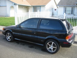
Dodge Colt 1989 Workshop Repair & Service Manual (COMPLETE & INFORMATIVE for DIY REPAIR)

Dodge Colt 1989 Workshop Repair & Service Manual (COMPLETE & INFORMATIVE for DIY REPAIR) ☆ ☆ ☆ ☆ ☆


INSTANT DOWNLOAD


* COMPLETE, Absolutely No Missing Pages!
* Official Service INFORMATION You Can Count On!
* Customer Satisfaction GUARANTEED!

This high QUALITY official manual for Dodge Colt 1989 is 100 percents COMPLETE and INTACT, no MISSING, CORRUPT pages, sections to freak you out! This manual is exactly as described. It is in the cross-platform PDF document format so that it works like a charm on all kinds of devices.

FORMAT: PDF
LANGUAGE: English
SIZE/PAGE: 1,126 + 328 Pages
OS: Windows/Mac OS X/Linux/Android/iOS

Vol. I Engine, Chassis & Body.pdf
Vol. II Electrical.pdf

MAKE: Dodge
MODEL: Colt (aka Plymouth Colt, Eagle Summit) (Colt Series 2000)
YEAR: 1989

INSTANT DELIVERY: A download link will be sent to you instantly after payment. Simply click on the link and save it to your computer. You can use this Manual as long as you wish with no restrictions.

CUSTOMER SATISFACTION: If there is ANY kind of problem with the item you purchased, just drop a quick email. Within HOURS the issue shall be taken care of.

PRINTABLE MANUAL WITH DIAGRAMS: Just print the manual out and start to work. You can also use the manual with your Tablet/Laptop in your garage.

REFUND/EXCHANGE POLICY: We sell high QUALITY products only. However if you encounter any problems with the item you purchased, another replacement link will be sent to you. If we’re at fault, you will get 100 percents refund.

Buy ☆THE BEST MANUAL ON THE INTERNET☆ from responsible seller and get instant download now without uncertainty or surprise.

This highly detailed workshop service repair manual for download contains virtually everything you will ever need to repair, maintain, rebuild, refurbish or restore Dodge Colt 1989. All diagnostic and repair procedures and gives you access to the same information that professional technicians and mechanics have. You can view and print out the complete repair procedures with this workshop service repair manual Download – you do not need to be skilled with a computer.

EXCERPTS:
GROUP / SECTION INDEX
Introduction and Master Troubleshooting
Lubrication and Maintenance
Front Suspension
Brakes – Service / Parking
Clutch
Cooling
Engine
Intake and Exhaust System
Fuel System
Rear Suspension
Steering – Manual / Power
Transaxle – Manual / Automatic
Wheels and Tires
Body
Heaters and Air Conditioning
Emission Control System

GROUP / SECTION INDEX
INTRODUCTION
ELECTRICAL
Electrical System Parts Location
Relay, Control Unit, Sensor, Inspection
Terminal, Fusible Link, Fuse, Grounding
Inspection of Harness Connector
Wiring Harness
Charging System
Starting System
Ignition System
Meters and Gauges
Lighting System
Column Switch
Wiper and Washer System
Horn System
Cigarette Lighter
Clock
Audio System
Rear Window Defogger

REAR DISC BRAKE PAD CHECK AND REPLACEMENT
NOSFUAB
1. Check brake pad thickness through caliper body check port.
Limit: 2.0 mm (.08 in.)
Caution –
1. When the limit is exceeded, replace the pads at both sides, and also the brake pads for the wheels on the opposite side at the same time.
2. If there is a significant difference in the thicknesses of the pads on the left and right sides, check the sliding condition of the piston, lock pin sleeve and guide pin sleeve.
2. Loosen the parking brake cable (from the vehicle interior), and disconnect the parking brake erid installed on the rear brake assembly.
3. Remove lock pin. Lift caliper assembly and retain with wires.
Caution
Do not smear special grease on lock pin or make it dirty.
4. Remove the following parts from caliper support.
1 CD Outer shim
2 Pad assembly
3 Pad clips C
4 Pad clips B
5. Measure hub torque with pad removed to measure brake drag torque after pad installation.
NOTE
To secure the disc to the hub, tighten the nuts.
6. Securely attach the pad clip to the caliper support.
Caution
Do not deposit grease or other dirt on pad or brake disc friction surfaces.


INSTANT DOWNLOAD


Posted on

Dodge Caliber 2007 Workshop Repair & Service Manual + Body Repair Manual (COMPLETE & INFORMATIVE for DIY REPAIR) ☆ ☆ ☆ ☆ ☆

Dodge Caliber 2007 Workshop Repair & Service Manual + Body Repair Manual
MDGCLB07OPES.PDF
Price: $14.99 USD

Dodge Caliber 2007 Workshop Repair & Service Manual + Body Repair Manual (COMPLETE & INFORMATIVE for DIY REPAIR) ☆ ☆ ☆ ☆ ☆

* COMPLETE, Absolutely No Missing Pages!
* Official Service INFORMATION You Can Count On!
* Customer Satisfaction GUARANTEED!

This high QUALITY official manual for Dodge Caliber 2007 is 100 percents COMPLETE and INTACT, no MISSING, CORRUPT pages, sections to freak you out! This manual is exactly as described. It is in the cross-platform PDF document format so that it works like a charm on all kinds of devices.

FORMAT: PDF
LANGUAGE: English
SIZE/PAGE: 5,815 + 332 Pages
OS: Windows/Mac OS X/Linux/Android/iOS

INSTANT DELIVERY: A download link will be sent to you instantly after payment. Simply click on the link and save it to your computer. You can use this Manual as long as you wish with no restrictions.

CUSTOMER SATISFACTION: If there is ANY kind of problem with the item you purchased, just drop a quick email. Within HOURS the issue shall be taken care of.

PRINTABLE MANUAL WITH DIAGRAMS: Just print the manual out and start to work. You can also use the manual with your Tablet/Laptop in your garage.

REFUND/EXCHANGE POLICY: We sell high QUALITY products only. However if you encounter any problems with the item you purchased, another replacement link will be sent to you. If we’re at fault, you will get 100 percents refund.

Buy ☆THE BEST MANUAL ON THE INTERNET☆ from responsible seller and get instant download now without uncertainty or surprise.

This highly detailed workshop service repair manual for download contains virtually everything you will ever need to repair, maintain, rebuild, refurbish or restore Dodge Caliber 2007. All diagnostic and repair procedures and gives you access to the same information that professional technicians and mechanics have. You can view and print out the complete repair procedures with this workshop service repair manual Download – you do not need to be skilled with a computer.

MDGCLB07OPES.PDF
Price: $14.99 USD

EXCERPTS:
GROUP TAB LOCATOR
Introduction
0 Lubrication & Maintenance
2 Suspension
3 Differential & Driveline
4 Vehicle Quick Reference
5 Brakes
6 Clutch
7 Cooling
8A Audio/Video
8B Chime/Buzzer
8E Electronic Control Modules
8F Engine Systems
8G Heated Systems
8H Horn
8I Ignition Control
8J Instrument Cluster
8L Lamps
8M Message Systems
8N Power Systems
😯 Restraints
8P Speed Control
8Q Vehicle Theft Security
8R Wipers/Washers
8T Navigation/Telecommunication
8W Wiring
9 Engine
11 Exhaust System
13 Frame & Bumpers
14 Fuel System
19 Steering
21 Transmission and Transfer Case
22 Tires/Wheels
23 Body
24 Heating & Air Conditioning
25 Emissions Control
Component and System Index
DTC Index
Service Manual Comment Forms (Rear of Manual)

ENGINE
TABLE OF CONTENTS
ENGINE ELECTRICAL DIAGNOSTICS – GPEC. . . . . 1
ENGINE ELECTRICAL DIAGNOSTICS – DIESEL . 939
ENGINE 1.8L WORLD. . . . . . . . . . . . 1441
ENGINE 2.0L WORLD. . . . . . . . . . . . 1543
ENGINE 2.4L WORLD. . . . . . . . . . . . 1653

FUEL DELIVERY
DESCRIPTION
The fuel tank is made of plastic and is located near the rear center of the vehicle.
The Fuel Delivery System consists of: the following items:
² Electric fuel pump module
² Fuel filter
² Tubes/lines/hoses
² Fuel injectors
The in-tank fuel pump module contains the fuel pump. The pump is serviced as part of the fuel pump module. Refer
to Fuel Pump Module.
The fuel filter is not serviceable, it is mounted on the inside of the fuel tank in the fuel pump module.
DIAGNOSIS AND TESTING – FUEL DELIVERY SYSTEM
(Refer to Group 9 Engine for all Powertrain Diagnostic Information)
STANDARD PROCEDURE
FUEL CONTAMINATION
If a engine’s fuel supply has been contaminated, the following procedure must be followed:
1. Remove all fuel from fuel tank. Use an appropriate fuel container. Dispose of contaminated fuel through the proper procedure of disposal. Clean fuel tank. This will require removal of the fuel tank to make sure all contaminated fuel is removed. (Refer to 14 – FUEL SYSTEM/FUEL DELIVERY/FUEL TANK – REMOVAL).
2. Install fuel tank to vehicle, (Refer to 14 – FUEL SYSTEM/FUEL DELIVERY/FUEL TANK – INSTALLATION).
3. Fill fuel tank with fuel.
4. Check for DTC’s and clear DTC’s.
5. Start vehicle and run engine for 15 minutes and turn off vehicle.
6. Check for DTC’s and clear DTC’s.
7. Road test vehicle.
8. Check for DTC’s.
NOTE: Dispose of Petroleum based products in a manner consistent with State, Federal, and Provincial Regulations.
The engine should then be evaluated to determine if the contaminated fuel has caused any damage to the fuel system and or engine. Indicators that the fuel system and or engine has been damaged are the following:
Unstable fuel rail pressure. This can manifest itself as instability at idle speeds, excessive undershoot/overshoot at engine start, or excessive undershoot/overshoot when the engine operating conditions change. A typical engine response to a large rail pressure undershoot would be a decrease in engine speed or engine stall.
Excessive noise from the engine. This could indicate poor rail pressure control or the inability of the injection system to inject the proper amount of fuel.
Excessive smoke (black or white). This could indicate inability of the fuel system to inject the proper amount of fuel.
NOTE: If any of these conditions are exhibited after cleaning the fuel system, proceed to the appropriate fuel system information. Repair fuel system and or engine as necessary.

Posted on

Daihatsu Terios 1997-2015 Workshop Repair & Service Manual / MANUAL DE SERVICIO (COMPLETE & INFORMATIVE for DIY REPAIR) ☆ ☆ ☆ ☆ ☆

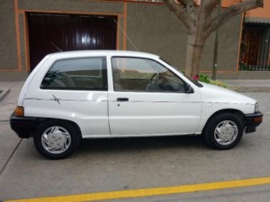
Daihatsu Terios 1997-2015 Workshop Repair & Service Manual / MANUAL DE SERVICIO

Daihatsu Terios 1997-2015 Workshop Repair & Service Manual / MANUAL DE SERVICIO (COMPLETE & INFORMATIVE for DIY REPAIR) ☆ ☆ ☆ ☆ ☆

MDHTTR9715OPMS.PDF
Price: $14.99 USD

* COMPLETE, Absolutely No Missing Pages!
* Official Service INFORMATION You Can Count On!
* Customer Satisfaction GUARANTEED!

This high QUALITY official manual for Daihatsu Terios 1997-2015 is 100 percents COMPLETE and INTACT, no MISSING, CORRUPT pages, sections to freak you out! This manual is exactly as described. It is in the cross-platform PDF document format so that it works like a charm on all kinds of devices.

FORMAT: PDF
LANGUAGE: English / Spanish
SIZE/PAGE: 480 MB
OS: Windows/Mac OS X/Linux/Android/iOS

’97-’99 Terios (J100)
’00-’05 Terios (J102)
’06-’15 Terios (J200-J200-J211)

“Chassis Service Manual”
“Engine Service Manual”
“Service Manual Transmission”
“BODY REPAIR MANUAL”
“Wiring Diagram Service Manual”
“TECHNICAL INFORMATION”

INSTANT DELIVERY: A download link will be sent to you instantly after payment. Simply click on the link and save it to your computer. You can use this Manual as long as you wish with no restrictions.

CUSTOMER SATISFACTION: If there is ANY kind of problem with the item you purchased, just drop a quick email. Within HOURS the issue shall be taken care of.

PRINTABLE MANUAL WITH DIAGRAMS: Just print the manual out and start to work. You can also use the manual with your Tablet/Laptop in your garage.

REFUND/EXCHANGE POLICY: We sell high QUALITY products only. However if you encounter any problems with the item you purchased, another replacement link will be sent to you. If we’re at fault, you will get 100 percents refund.

Buy ☆THE BEST MANUAL ON THE INTERNET☆ from responsible seller and get instant download now without uncertainty or surprise.

This highly detailed workshop service repair manual for download contains virtually everything you will ever need to repair, maintain, rebuild, refurbish or restore Daihatsu Terios 1997-2015. All diagnostic and repair procedures and gives you access to the same information that professional technicians and mechanics have. You can view and print out the complete repair procedures with this workshop service repair manual Download – you do not need to be skilled with a computer.

Daihatsu Terios 1997-2015

MDHTTR9715OPMS.PDF
Price: $14.99 USD

EXCERPTS:

EFI SYSTEM (3SZ-VE, K3-VE)
BASIC INSPECTION
HINT:
If the malfunction cannot be determined by troubleshooting, the problem area can be narrowed down by performing the following basic inspection.
1. CHECK BATTERY VOLTAGE
(a) Check the condition of the battery.(See page CH – 3.)
2. CHECK WHETHER ENGINE CRANKS
(a) Make sure that the engine cranks.
HINT:
If the engine does not crank, check the starting systems.
3. CHECK WHETHER ENGINE STARTS
(a) Make sure that the engine starts.
HINT:
If the engine does not start, check fuel pressure and spark.
4. CHECK AIR FILTER
(a) Check the air filter.
HINT:
If the air filter is dirty, clean or replace it.
5. CHECK ENGINE IDLE SPEED (See page EM – 2)
6. CHECK IGNITION TIMING (See page EM – 1)
7. CHECK FUEL PRESSURE (See page FU – 3)
8. CHECK FOR SPARK (See page IG – 1)
9. CHECK COMPRESSION (See page EM – 2)

SRS AIRBAG SYSTEM
OPERATION CHECK
1. CHECK AIRBAG WARNING LIGHT
(a) Check that the warning light comes on when the ignition switch is turned on (IG).
(b) Check that the warning light goes off approximately 6 seconds after the ignition switch is turned on (IG).
HINT:
• If the warning light remains on for more than approximately 6 seconds after the ignition switch is turned on (IG), there is a malfunction in the airbag and pretensioner system.
• If the warning light continues to come on occasionally even after approximately 6 seconds has elapsed after the ignition switch is turned on (IG), the cause may be a short to the +B of the airbag warning system or a short or open ground.
• If the light remains on even when the ignition switch is turned off or to the ACC position, there may be a failure in the power supply system or in the combination meter
assembly.
2. CHECK HORN BUTTON ASSEMBLY
(a) For vehicles that have not been involved in a collision:
(1) If there are any of the following symptoms, replace the horn button assembly with a new one.
Standard: There are cracks, dents or chips on the horn button assembly pad surface.
(b) For vehicles that have been involved in a collision without the airbags being deployed:
CAUTION:
Follow these procedures correctly when replacing the horn button assembly.
(1) If there are any of the following symptoms when removing the horn button assembly, replace the assembly with a new one.
Standard:
There are cracks, dents or chips on the horn button assembly pad surface.
There are scratches, abrasions, cracks or other damage to the connector and wire harness.
The horn button assembly has been dropped.

Posted on

Daihatsu Charade 1987-1993 Workshop Repair & Service Manual (COMPLETE & INFORMATIVE for DIY REPAIR) ☆ ☆ ☆ ☆ ☆

Daihatsu Charade 1987-1993 Workshop Repair & Service Manual (COMPLETE & INFORMATIVE for DIY REPAIR)
MDHTCRD8793OPES.PDF
Price: $12.99 USD

Daihatsu Charade 1987-1993 Workshop Repair & Service Manual (COMPLETE & INFORMATIVE for DIY REPAIR) ☆ ☆ ☆ ☆ ☆

* COMPLETE, Absolutely No Missing Pages!
* Official Service INFORMATION You Can Count On!
* Customer Satisfaction GUARANTEED!

This high QUALITY official manual for Daihatsu Charade 1987-1993 is 100 percents COMPLETE and INTACT, no MISSING, CORRUPT pages, sections to freak you out! This manual is exactly as described. It is in the cross-platform PDF document format so that it works like a charm on all kinds of devices.

FORMAT: PDF
LANGUAGE: English
SIZE/PAGE: 989 Pages
OS: Windows/Mac OS X/Linux/Android/iOS

’87-’93 Charade (G100, G102 Series)
Daihatsu Type CB Engine (CB-23, CB-61 & CB-80)

INSTANT DELIVERY: A download link will be sent to you instantly after payment. Simply click on the link and save it to your computer. You can use this Manual as long as you wish with no restrictions.

CUSTOMER SATISFACTION: If there is ANY kind of problem with the item you purchased, just drop a quick email. Within HOURS the issue shall be taken care of.

PRINTABLE MANUAL WITH DIAGRAMS: Just print the manual out and start to work. You can also use the manual with your Tablet/Laptop in your garage.

REFUND/EXCHANGE POLICY: We sell high QUALITY products only. However if you encounter any problems with the item you purchased, another replacement link will be sent to you. If we’re at fault, you will get 100 percents refund.

Buy ☆THE BEST MANUAL ON THE INTERNET☆ from responsible seller and get instant download now without uncertainty or surprise.

This highly detailed workshop service repair manual for download contains virtually everything you will ever need to repair, maintain, rebuild, refurbish or restore Daihatsu Charade 1987-1993. All diagnostic and repair procedures and gives you access to the same information that professional technicians and mechanics have. You can view and print out the complete repair procedures with this workshop service repair manual Download – you do not need to be skilled with a computer.

MDHTCRD8793OPES.PDF
Price: $12.99 USD

Daihatsu Charade 1987-1993 Workshop Repair & Service Manual (COMPLETE & INFORMATIVE for DIY REPAIR) ☆ ☆ ☆ ☆ ☆

EXCERPTS:
FRONT AXLE & SUSPENSION
1. Disc brake cover replacement
(1) Separate the disc brake cover from the knuckle, using a common screwdriver or the like.
NOTE:
Do not remove the disc brake cover unless its replacement is required.
(2) Press the disc brake cover until it comes into close contact with the knuckle, using the following SSTs. SST: 09506-87302-000 09718-87701-000
INSTALLATION
1. Front axle bearing installation
(1) Press the bearing into position, using the following
SSTs. SST: 09506-87302-000 09550-10012-000 (09554-10010-000, part of the proceeding tool)
(2) Install a new snap ring, using snap ring pliers.
(3) Press the front axle hub into position, using the following SST. SST: 09550-10012-000 (09554-10010-000, part of the proceeding tool)
2. Steering knuckle installation
(1) Insert the steering knuckle into the drive shaft.
NOTE:
• Be careful not to allow the drive shaft to come into contact with the oil seal at the knuckle side.
• Pay utmost attention not to damage the ball joint dust
cover.
(2) Mount the steering knuckle on the lower ball joint.
(3) Mount the steering knuckle on the shock absorber lower bracket. Tighten the bolts and nuts.
Tightening Torque: 9.0 – 13.0 kg-m (65 – 94 ft-lb)
NOTE:
With the knuckle pushed against the lower side, tighten the bolts and nuts.
(4) Install the lower ball joint. Tighten the bolt and nut. Tightening Torque: 8.0 – 10.5 kg-m (58 – 76 ft-lb)
(5) Install the washer. Install the nut temporarily.
NOTE: Be sure to install the washer in the correct direction.

3. Install the disc rotor.
NOTE:
Care must be exercised to ensure that no foreign matter lodge between the hub and the disc rotor.
4. Disc brake caliper installation
(1) Install the pad guide plate to the steering knuckle.
(2) Tighten the attaching bolts of the disc brake caliper. Tightening Torque: 3.2 – 4.2 kg-m (23 – 30 ft-lb).