Posted on

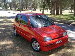
1991-1998 Cinquecento Workshop Repair & Service Manual in Italian (COMPLETE & INFORMATIVE for DIY REPAIR) ☆ ☆ ☆ ☆ ☆

1991-1998 FIAT Cinquecento Workshop Repair & Service Manual in Italian (COMPLETE & INFORMATIVE for DIY REPAIR)

MFIATCQCT9198OPIK.PDF
Price: $14.99 USD

1991-1998 FIAT Cinquecento Workshop Repair & Service Manual in Italian (COMPLETE & INFORMATIVE for DIY REPAIR) ☆ ☆ ☆ ☆ ☆

* COMPLETE, Absolutely No Missing Pages!
* Official Service INFORMATION You Can Count On!
* Customer Satisfaction GUARANTEED!

This high QUALITY official manual for ’91-’98 Cinquecento is 100 percents COMPLETE and INTACT, no MISSING, CORRUPT pages, sections to freak you out! This manual is exactly as described. It is in the cross-platform PDF document format so that it works like a charm on all kinds of devices.

FORMAT: PDF
LANGUAGE: ITALIAN
SIZE/PAGE: 2,673 Pages
OS: Windows/Mac OS X/Linux/Android/iOS

INSTANT DELIVERY: A download link will be sent to you instantly after payment. Simply click on the link and save it to your computer. You can use this Manual as long as you wish with no restrictions.

CUSTOMER SATISFACTION: If there is ANY kind of problem with the item you purchased, just drop a quick email. Within HOURS the issue shall be taken care of.

PRINTABLE MANUAL WITH DIAGRAMS: Just print the manual out and start to work. You can also use the manual with your Tablet/Laptop in your garage.

REFUND/EXCHANGE POLICY: We sell high QUALITY products only. However if you encounter any problems with the item you purchased, another replacement link will be sent to you. If we’re at fault, you will get 100 percents refund.

Buy ☆THE BEST MANUAL ON THE INTERNET☆ from responsible seller and get instant download now without uncertainty or surprise.

This highly detailed workshop service repair manual for download contains virtually everything you will ever need to repair, maintain, rebuild, refurbish or restore 1991 1992 1993 1994 1995 1996 1997 1998 Cinquecento. All diagnostic and repair procedures and gives you access to the same information that professional technicians and mechanics have. You can view and print out the complete repair procedures with this workshop service repair manual Download – you do not need to be skilled with a computer.

EXCERPTS:
Impianto elettrico
Accensione elettronica nanoplex
ACCENSIONE ELETTRONICA AD ANTICIPO E DISTRIBUZIONE STATICA NANOPLEX
Generalità
Il sistema di accensione adottato su questo motore bicilindrico è denominato Nanoplex ed è un sistema di accensione elettronica ad anticipo e distribuzione statico (cioè non avente alcuna parte in movimento) a scintilla persa.
Il sistema è composto da un microprocessore che conosce lo stato di funzionamento del motore attraverso ad alcuni sensori periferici ed aziona la corrente di carica del rocchetto d’accensione per il tempo (valore della corrente di carica) ed al momento (angolo di anticipo accensione) più opportuni secondo le mappature memorizzate in due curve d’anticipo. L’angolo di anticipo adottato è in funzione del numero dei giri e del carico motore istantanei.
Questo sistema è costituito dai seguenti particolari.
a) Un sensore elettromagnetico (2) affacciato alla puleggia albero motore che fornisce al modulo elettronico di comando accensione le informazioni di numero di giri motore nell’unità di tempo e posizione di P.M.S. degli stantuffi.
b) Una puleggia albero motore (3) specifica sulla cui circonferenza sono ricavati tre risalti (o denti) che servono al sensore per produrre dei segnali di numero di giri e P.M.S. stantuffi.
c) Un modulo elettronico, o centralina, (1) comando accensione che in funzione dei valori istantanei del numero di giri, della posizione di P.M.S. e del funzionamento del motore (a pieno carico oppure a carichi parziali) piloti per il tempo opportuno la corrente di conduzione del primario (da 7, 1 A al minimo a 3,5 A a 5900/min) e la interrompa istantaneamente; inoltre, in fase di avviamento, garantisca il funzionamento del motore anche con tensioni della batteria di 6V, mentre a 1000/min lo deve garantire con tensioni tra 6 e 1 O V.; infine tagli l’alimentazione al primario a 6000/min e la riattivi a 5900/min. e mantenga negli angoli d’anticipo d’accensione delle tolleranze di ± 2° da 450 /min al massimo regime, di – 2° da 200/min-;- 400/min ed infine, in fase di avviamento, un ritardo massimo di – 8° fino a 200/min.
d) Un interruttore a depressione, o manocontatto, (4) che serve da ingresso aperto-chiuso (ON-OFF) di segnale logico delle condizioni di pieno carico o carico parziale del motore affinché il microprocessore di comando del sistema accensione adotti, delle due curve disponibili, quella più appropriata alle condizioni di funzionamento del motore.
e) Un rocchetto di accensione (5) con doppio terminale ad alta tensione costituito da un avvolgimento primario a bassa induttanza (alimentato dalla tensione di batteria) e da un avvolgimento se- .1 conciario (alta tensione) le cui due uscite sono direttamente collegate alle candele cui provvedono a mandare l’alta tensione ogni qualvolta avviene la smagnetizzazione del primario da parte del modulo elettronico di comando.
L’alta tensione che alimenta contemporaneamente le due candele, data la caratteristica di chiusura del circuito secondario (candela posta in serie) sarà di intensità diversa. Ciò è dovuto al fatto che periodicamente una delle due candele si troverà in condizioni di maggior pressione (fase di compressione) nei confronti dell’altra (fase di scarico) cosicché la corrente, dovendo vincere un maggior dielettrico nella candela che si troverà in fase di compressione, darà origine ad una scintilla più potente in questa, mentre nell’altra sarà irrisoria (limitandone il consumo).
L’accensione Nanoplex dispone di una funzione diagnosi su una linea bidirezionale che esegue in “input” la diagnosi attiva ed in “output” l’autodiagnosi, cosicché con il Fiat-Lancia tester è possibile colloquiare con il sistema d’accensione per ottenere i’AUTODiAGNOSi del sistema.
E una induttanza variabile – composta da una calamita e da un avvolgimento – che si rafforza quando un risalto della puleggia albero motore s’affaccia alla calamita e si indebolisce ed inverte quando il risalto s’allontana. Durante il funzionamento del motore si sviluppa nel sensore una f.e.m. alternata (la cui frequenza viene utilizzata per leggere i giri motore) con una irregolarità di frequenza (che serve ad individuare il PMS).

MFIATCQCT9198OPIK.PDF
Price: $14.99 USD

Posted on

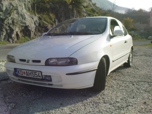
Fiat Bravo, Brava 1995-2001 Workshop Repair & Service Manual (COMPLETE & INFORMATIVE for DIY REPAIR) ☆ ☆ ☆ ☆ ☆

Fiat Bravo, Brava 1995-2001 Workshop Repair & Service Manual (COMPLETE & INFORMATIVE for DIY REPAIR) ☆ ☆ ☆ ☆ ☆

MFIATBRV9501OPMS.PDF
Price: $14.99 USD

Fiat Bravo, Brava 1995-2001 Workshop Repair & Service Manual (COMPLETE & INFORMATIVE for DIY REPAIR) ☆ ☆ ☆ ☆ ☆

* COMPLETE, Absolutely No Missing Pages!
* Official Service INFORMATION You Can Count On!
* Customer Satisfaction GUARANTEED!

This high QUALITY official manual for Fiat Bravo, Brava 1995-2001 is 100 percents COMPLETE and INTACT, no MISSING, CORRUPT pages, sections to freak you out! This manual is exactly as described. It is in the cross-platform PDF document format so that it works like a charm on all kinds of devices.

MAKE: FIAT
MODEL: Bravo, Brava
YEAR: 1995 1996 1997 1998 1999 2000 2001
LANGUAGE: EN/IT
FORMAT: PDF
SIZE/PAGE: 383 MB (10,000+ Pages)

INSTANT DELIVERY: A download link will be sent to you instantly after payment. Simply click on the link and save it to your computer. You can use this Manual as long as you wish with no restrictions.

CUSTOMER SATISFACTION: If there is ANY kind of problem with the item you purchased, just drop a quick email. Within HOURS the issue shall be taken care of.

PRINTABLE MANUAL WITH DIAGRAMS: Just print the manual out and start to work. You can also use the manual with your Tablet/Laptop in your garage.

REFUND/EXCHANGE POLICY: We sell high QUALITY products only. However if you encounter any problems with the item you purchased, another replacement link will be sent to you. If we’re at fault, you will get 100 percents refund.

Buy ☆THE BEST MANUAL ON THE INTERNET☆ from responsible seller and get instant download now without uncertainty or surprise.

This highly detailed workshop service repair manual for download contains virtually everything you will ever need to repair, maintain, rebuild, refurbish or restore Fiat Bravo, Brava 1995-2001. All diagnostic and repair procedures and gives you access to the same information that professional technicians and mechanics have. You can view and print out the complete repair procedures with this workshop service repair manual Download – you do not need to be skilled with a computer.

EXCERPTS:
HITACHI INTEGRATED INJECTION/IGNITION SYSTEM
Introduction
The Hitachi system fitted on the Bravo-Brava with the 1747 i.e 16v engine belongs to the category of static advance digital electronic ignition systems integrated with multiple phased type intermittent electronic fuel injection systems.
This system therefore has only one control unit, one set of wiring and one set of common sensors for both systems.
The integrated system can be summarized in the following sub systems:
ELECTRICAL/ELECTRONIC CIRCUIT
AIR INTAKE CIRCUIT
FUEL SUPPLY CIRCUIT
EMISSION CONTROL DEVICES
The system is capable of detecting the following parameters via special sensors:
1 . the engine rotation speed;
2. the position of each pair of pistons in relation to TDC for cylinder 1;
3. the engine intake air flow rate;
4. the position and the speed of the variation of the position of the accelerator butterfly;
5. the temperature of the engine coolant;
6. the effective strength of the mixture (through the Lambda sensor signal);
7. the presence of detonation;
8. the speed of the vehicle;
9. the battery voltage;
10. whether the climate control compressor is switched on.
This information, usually of an analogue type, is converted into digital signals by analogue/digital (A/D) converters in order to be able to be used by the control unit.
In particular, any engine operating point is detected, moment by moment, by two parameters:
– the engine rotation speed, measured in revolutions per minute (rpm);
– the engine load, which is constituted by the quantity of air drawn in by each cylinder.
This quantity is calculated on the basis of the flow rate of the air drawn in and is represented by the parameter TP, measured in milliseconds (ms).
Inside the control unit memory there is a management program (software) which comprises a series of strategies, each of which manages a precise system control function.
By using the (input) information listed previously, each strategy processes a series of parameters, based on the data maps stored in the control unit memories and then controls the system (output) actuators which are the devices which allow the engine to operate, namely:
1. injectors;
2. ignition coils;
3. solenoid valves implementing various functions;
4. fuel pump;
5. control relays.
NOTE The HITACHI injection/ignition system does not require any adjustment as it is self-regulating and self-adjusting.
NOTE In the diagrams, the numbers indicate the corresponding HITACHI engine control unit pins.
NOTE All the connectors are seen from the side opposite the cable input.


MFIATBRV9501OPMS.PDF
Price: $14.99 USD

Posted on

Fiat Bravo 2007-2010 Workshop Repair & Service Manual (COMPLETE & INFORMATIVE for DIY REPAIR) ☆ ☆ ☆ ☆ ☆

Fiat Bravo 2007-2010 Workshop Repair & Service Manual (COMPLETE & INFORMATIVE for DIY REPAIR)

MFIATBRV0710NMMK
Price: $14.99 USD

Fiat Bravo 2007-2010 Workshop Repair & Service Manual (COMPLETE & INFORMATIVE for DIY REPAIR) ☆ ☆ ☆ ☆ ☆

* COMPLETE, Absolutely No Missing Pages!
* Official Service INFORMATION You Can Count On!
* Customer Satisfaction GUARANTEED!

This high QUALITY official manual for Fiat Bravo 2007-2010 is 100 percents COMPLETE and INTACT, no MISSING, CORRUPT pages, sections to freak you out! This manual is exactly as described.

MAKE: Fiat
MODEL: Nuova Bravo (Type 198 New Bravo, aka Ritmo) (1.4 16V-16V TJet, 1.9 JTD 8V-16V)
YEAR: 2007, 2008, 2009, 2010
LANGUAGE: EN/DE/ES/FR/IT/NL/PL/GK/PT/CZ/TR

INSTANT DELIVERY: A download link will be sent to you instantly after payment. Simply click on the link and save it to your computer. You can use this Manual as long as you wish with no restrictions.

CUSTOMER SATISFACTION: If there is ANY kind of problem with the item you purchased, just drop a quick email. Within HOURS the issue shall be taken care of.

PRINTABLE MANUAL WITH DIAGRAMS: Just print the manual out and start to work. You can also use the manual with your Tablet/Laptop in your garage.

REFUND/EXCHANGE POLICY: We sell high QUALITY products only. However if you encounter any problems with the item you purchased, another replacement link will be sent to you. If we’re at fault, you will get 100 percents refund.

Buy ☆THE BEST MANUAL ON THE INTERNET☆ from responsible seller and get instant download now without uncertainty or surprise.

This highly detailed workshop service repair manual for download contains virtually everything you will ever need to repair, maintain, rebuild, refurbish or restore Your Fiat Bravo 2007-2010 (ALL MODELS ARE COVERED). All diagnostic and repair procedures and gives you access to the same information that professional technicians and mechanics have. You can view and print out the complete repair procedures with this workshop service repair manual Download – you do not need to be skilled with a computer.

EXCERPTS:
NUOVA BRAVO 1.4 16v INTRODUCTION – BRAKE PUMP, RESERVOIR AND LOAD PROPORTIONING VALVE
CONSTRUCTION SPECIFICATIONS
A large diameter (10″) Bosch brake servo with an aluminium pump and extended stroke has been adopted to guarantee plenty of pedal travel in reserve even in extreme overheating conditions caused by intensive usage.
The hydraulic braking system reserve fluid reservoir is press-fitted on the top part of the pump.
There is an attachment on the reservoir for connecting the hydraulic clutch release system supply pipe.
There is an insufficient fluid level sensor on the reservoir which is activated when the fluid is below the minimum level, signalling this condition to the Body Computer, which then lights up the warning light on the instrument panel.
1. Brake fluid reservoir
2. Brake servo
3. Brake pedal
4. Clutch pump supply pipe attachment
5. Aluminium master cylinder
6. Insufficient brake fluid level sensor
SPECIFICATIONS
The vehicle is equipped with a system that cleans and washes the front windscreen. The vehicle may be fitted as an option with a pressurized liquid washing system for the front headlamps.
Reservoir
The reservoir is located in the left side of the wheel arch compartment and it allows the screen washer system pump to supply the water-antifreeze mixture required to clean the front window. If the vehicle is equipped with the relevant option, it also supplies the headlamp washer system via a special pump.
The reservoir capacity ensures a minimum of 25 washing cycles and it ranges in size from a minimum of about 5 litres for the version without a headlamp washer to up to around 6 litres if equipped with a headlamp washer.
The reservoir is made out of plastic and contains external housings for the pump that supplies the windscreen washer and headlamp washers (if fitted).
1 – Windscreen washer fluid reservoir
2 – Pump supplying fluid to the nozzles
Controls
The control of the wiping functions and, in particular, of the:
– windscreen wiper: sweep rate;
– rearscreen wiper: sweep rate and control during reversing;
– windscreen wiper function: smart washing;
– rearscreen washer function: smart washing;
is managed by the electronic module inside the steering column switch unit.
The right lever allows the activation of the various functions.
Operation
Windscreen wiper
Manual mode operation
– Pos. A: OFF
– Pos. B: Intermittent / Automatic
– Pos. C: Continuous 1st speed
– Pos. D: Continuous 2nd speed
– Pos. E: Anti-panic (temporary speed – unstable)
When the ring nut for the steering column switch unit right lever is moved downwards, to one of the three positions:
– intermittent
– first speed continuous
– second speed continuous
the windscreen wiper motor is activated according to the following logic.
Intermittent: the windscreen wiper is operated at the first speed but with a pause between one stroke and the next, that varies according to the speed of the vehicle (from a minimum of 1.1 secs. above 110 km/h to a maximum of 4.7 secs with the vehicle stationary).
First speed continuous: the windscreen wiper is operated at the first speed at 45 strokes/minute.
Second speed continuous: the windscreen wiper is operated at the second speed at 65 strokes/minute.


MFIATBRV0710NMMK
Price: $14.99 USD

Posted on

Fiat Barchetta 1995-2002 Workshop Repair & Service Manual (COMPLETE & INFORMATIVE for DIY REPAIR) ☆ ☆ ☆ ☆ ☆

Fiat Barchetta 1995-2002 Workshop Repair & Service Manual (COMPLETE & INFORMATIVE for DIY REPAIR)

MFIATBCT9502OPES.PDF
Price: $14.99 USD

Fiat Barchetta 1995-2002 Workshop Repair & Service Manual (COMPLETE & INFORMATIVE for DIY REPAIR) ☆ ☆ ☆ ☆ ☆

* COMPLETE, Absolutely No Missing Pages!
* Official Service INFORMATION You Can Count On!
* Customer Satisfaction GUARANTEED!

This high QUALITY official manual for Fiat Barchetta 1995-2002 is 100 percents COMPLETE and INTACT, no MISSING, CORRUPT pages, sections to freak you out! This manual is exactly as described. It is in the cross-platform PDF document format so that it works like a charm on all kinds of devices.

FORMAT: PDF
LANGUAGE: English
OS: Windows/Mac/Linux
SIZE: 956 MB

Fiat Barchetta (Type 183) 1995 1996 1997 1998 1999 2000 2001 2002

INSTANT DELIVERY: A download link will be sent to you instantly after payment. Simply click on the link and save it to your computer. You can use this Manual as long as you wish with no restrictions.

CUSTOMER SATISFACTION: If there is ANY kind of problem with the item you purchased, just drop a quick email. Within HOURS the issue shall be taken care of.

PRINTABLE MANUAL WITH DIAGRAMS: Just print the manual out and start to work. You can also use the manual with your Tablet/Laptop in your garage.

REFUND/EXCHANGE POLICY: We sell high QUALITY products only. However if you encounter any problems with the item you purchased, another replacement link will be sent to you. If we’re at fault, you will get 100 percents refund.

Buy ☆THE BEST MANUAL ON THE INTERNET☆ from responsible seller and get instant download now without uncertainty or surprise.

This highly detailed workshop service repair manual for download contains virtually everything you will ever need to repair, maintain, rebuild, refurbish or restore Your Fiat Barchetta 1995-2002 (ALL MODELS ARE COVERED). All diagnostic and repair procedures and gives you access to the same information that professional technicians and mechanics have. You can view and print out the complete repair procedures with this workshop service repair manual Download – you do not need to be skilled with a computer.

EXCERPTS:
Fan activation operating diagram for air conditioned specifications
Low speed fan: comes on when coolant temperature reaches 95°C.
High speed fan: comes on when coolant temperature reaches 100°C: the first fan is activated after the second.
Fan activation is dependent on the status of air conditioning system three-level pressure switch because this determines whether the first fan will come on, followed after a certain delay by the second, and also controls subsequent de-activation.
1. Condition of three-level pressure switch
2. Condition of high speed fan
3. Condition of low speed fan
4. Coolant temperature curve
5. Delay in three-level pressure switch activation/deactivation
ON: fan/pressure switch active
OFF: fan/pressure switch de-active

AIR FLOW METER
The air flow meter is hot-wire type and measures air flow indirectly.
A duct through the top of the meter and parallel to the main flow contains a hot wire.
Part. of the air intake passes into the duct and rejoins the main flow at the other end.
Only a proportion of the air mass flowing through the meter is therefore measured. This
quantity is nevertheless proportional to the overall mass flowing through the meter.
Meter electrical output is there representative of total flow, which is calculated by applying appropriate ratios.
This type of meter offers two advantages over a full flow meter:
– hardly susceptible to air column pulses, particularly common at low speeds with high loads;
– less fouling of the filament due to the reduced mass of air flowing over it. The ECU does not need to clean the wire (burn-in).

LAMBDA PROBE
The lambda probe measures exhaust gas oxygen content. It is fitted on the exhaust pipe upstream of the catalytic converter.
The sensor output signal is sent to the ECU to correct mixture concentration retro-actively (feed-back).
When the probe supplies a low signal (voltage less than 200 mV) the ECU identifies a lean mixture and increases injection time; when the probe signal is high (voltage higher than 800 mV), the ECU identifies a rich mixture and decreases injection time.
This sequence repeats itself at a rate in the order of tens of Hertz to ensure the engine runs on a mixture continually oscillating about stoichiometric levels.
At temperatures less than 300°C the ceramic material is inactive and the probe does not send reliable signals: the probe is fitted with a permanently active electrical heating coil to ensure rapid heating upon start-up and maintain temperature at minimum levels.


MFIATBCT9502OPES.PDF
Price: $14.99 USD

Posted on

Fiat 500 2007-2010 Workshop Repair & Service Manual [COMPLETE & INFORMATIVE for DIY REPAIR] ☆ ☆ ☆ ☆ ☆

Fiat New 500 2007-2010 Workshop Repair & Service Manual [COMPLETE & INFORMATIVE for DIY REPAIR]

Fiat New 500 2007-2010 Workshop Repair & Service Manual [COMPLETE & INFORMATIVE for DIY REPAIR] ☆ ☆ ☆ ☆ ☆


MFIAT5000710NMMK
Price: $14.99 USD

* COMPLETE, Absolutely No Missing Pages!
* Official Service INFORMATION You Can Count On!
* Customer Satisfaction GUARANTEED!

This high QUALITY official manual for Fiat 500 2007-2010 is 100 percents COMPLETE and INTACT, no MISSING, CORRUPT pages, sections to freak you out! This manual is exactly as described.

MAKE: Fiat
MODEL: Nuova 500 (Type 312 New 500) (1.2 8V, 1.3 Multijet, 1.4 16V/TB)
YEAR: 2007 2008 2009 2010
LANGUAGE: EN/DE/ES/FR/IT/NL/PL/GK/PT/CZ/TR

INSTANT DELIVERY: A download link will be sent to you instantly after payment. Simply click on the link and save it to your computer. You can use this Manual as long as you wish with no restrictions.

CUSTOMER SATISFACTION: If there is ANY kind of problem with the item you purchased, just drop a quick email. Within HOURS the issue shall be taken care of.

PRINTABLE MANUAL WITH DIAGRAMS: Just print the manual out and start to work. You can also use the manual with your Tablet/Laptop in your garage.

REFUND/EXCHANGE POLICY: We sell high QUALITY products only. However if you encounter any problems with the item you purchased, another replacement link will be sent to you. If we’re at fault, you will get 100 percents refund.

Buy ☆THE BEST MANUAL ON THE INTERNET☆ from responsible seller and get instant download now without uncertainty or surprise.

MAKE: FIAT
MODEL: Nuova 500 (Type 312 New 500) (1.2 8V, 1.3 Multijet, 1.4 16V, 1.4 TB)
YEAR: 2007 2008 2009 2010
LANGUAGE: EN/DE/ES/FR/IT/NL/PL/GK/PT/CZ/TR
O.S.: Windows

TABLE OF CONTENTS:

TECHNICAL DATA
VEHICLE INTRODUCTION
PROJECT SPECIFICATIONS AND DESCRIPTIONS
CONSTRUCTION DATA
TIGHTENING TORQUES
PRODUCTS
SPECIAL TOOLS

DESCRIPTIONS
10 ENGINE
18 CLUTCH UNIT
21 GEARBOX UNIT
27 AXLE
33 BRAKES
41 STEERING UNIT
44 SUSPENSION AND WHEELS
50 AUXILIARY UNITS
55 ELECTRICAL EQUIPMENT
70 FITTINGS
72 PANELS AND FRAMES

FAULT DIAGNOSIS
B STARTING
C GEAR SHIFT
D ENGINE
E CLUTCH
F BRAKES
G HANDBRAKE
H STEERING (VEHICLE BEHAVIOUR)
I LIGHTS
J WINDSCREEN / REARSCREEN / REAR VIEW MIRRORS (VISIBILITY)
K INSTRUMENT PANEL
L CLIMATE CONTROL
M WINDOW OPENING MECHANISM
N RADIO AND ACCESSORIES ETC..
O SEATS
P DOORS
Q SUN ROOF
S NOISE / VIBRATIONS
T WIND NOISE
U ODOURS
V WATER PENETRATION
W EMISSIONS
X CONSUMPTION /LEAKS/ WEAR

TEST
10 ENGINE
33 BRAKES
44 SUSPENSION AND WHEELS
50 AUXILIARY UNITS
55 ELECTRICAL EQUIPMENT
70 FITTINGS

PROCEDURES
00 MAINTENANCE
05 DIAGNOSTICS
10 ENGINE
18 CLUTCH UNIT
21 GEARBOX UNIT
27 AXLE
33 BRAKES
41 STEERING UNIT
44 SUSPENSION AND WHEELS
50 AUXILIARY UNITS
55 ELECTRICAL EQUIPMENT
70 FITTINGS
72 PANELS AND FRAMES

ELECTRICAL EQUIPMENT
1 ELECTRICAL FUNCTIONS
2 WIRING
3 CONNECTORS

EXAMINER FAULT DIAGNOSIS
825 Marelli 6F3 EOBD CAN Diesel Injection (EP eng. 1.3 JTD) 2

EXCERPTS:
The crankcase is made of high mechanical strength cast iron.
The crankshaft is supported by five main bearings.
The cylinders are formed directly in the crankcase and sorted into three size categories plus one oversize.
Special channels in the crankcase walls carry coolant and lubrication fluid.

Made from induction hardened cast iron. Resting on five main bearings with interposed half-bearings divided into size categories.
The crankshaft endfloat is adjusted by two half-rings housed on the middle main bearing.
Eight counterweights arranged at 180° accurately balance the crankshaft rotating masses.
A channel running along the length of the shaft lubricates the main journals and crankpins.
The crankshaft consists of:
main journals (1), through which it rotates on main bearings with bearings (washers) in between; crank pins (2) above which the connecting rod big ends are hinged;
crank arms (3), with height equal to half the length of the travel, which join the main journals and the crank pins.
In addition, the shaft is also prepared for:
the fitting of the flywheel; fitting the gear which transmits power to the timing system components by means of a toothed belt.
OPERATION
The crankshaft consists of:
main journals (1), through which it rotates on main bearings with bearings (washers) in between; crank pins (2) above which the connecting rod big ends are hinged;
crank arms (3), with height equal to half the length of the travel, which join the main journals and the crank pins.
OPERATION
There are two types of firing order: 1, 2, 4, 3 or 1, 3, 4, 2; the best known one is firing order 1, 3, 4, 2 because the centrifugal forces and the inertia forces are better balanced.

NUOVA FIAT 500 1.2 8v STEERING CONTROL 4110A
Introduction
The NGE (Electrical Steering Node) produced by DELPHI has a power-assisted steering device which is designed to lighten the effort required from the driver on the steering wheel especially during steering maneuvers at low speed without, however, making it too light in normal driving conditions.
Electric power steering offers the following advantages compared with hydraulic power steering:
The system has fewer components and therefore weighs less and is less complex.
The installation and/or servicing times are reduced and simpler.
The electric power steering system only absorbs energy from the engine when servo-assistance is requested, improving the performance of the vehicle and reducing fuel consumption and emissions.
A reduction in operating noise improves driving comfort.
Reduction in pollution because the electrical energy used is clean.
Variation in power assistance depending on vehicle speed.
Steering return to the centre (active return)
Steering return oscillation damping
Selectable power assisted steering (Normal / City / Sport)
Components
Steering column
The electrical column is height-adjustable, with a total travel of 5 degrees; the mechanical column has a fixed position
To adjust the position bring lever (1) down to position A after which the steering wheel can be adjusted to the most suitable position and subsequently locked in this position by bringing lever A to position 1.
Steering wheel column composition


MFIAT5000710NMMK
Price: $14.99 USD