Complete digital official shop manual contains service, maintenance, and troubleshooting information for the BMW 528i/528xi/528e 1979-2016. Diagnostic and repair procedures are covered in great detail to repair, maintain, rebuild, refurbish or restore your vehicle like a professional mechanic in local service/repair workshop. This cost-effective quality manual is 100% complete and intact as should be without any missing pages. It is the same factory shop manual used by dealers that guaranteed to be fully functional to save your precious time.
This manual for BMW 528i/528xi/528e 1979-2016 is divided into different sections. Each section covers a specific component or system and, in addition to the standard service procedures, includes disassembling, inspecting, and assembling instructions. A table of contents is placed at the beginning of each section. Pages are easily found by category, and each page is expandable for great detail. It is in the cross-platform PDF document format so that it works like a charm on all kinds of devices. You do not need to be skilled with a computer to use the manual.
528i: 1979-2016
528xi: 2008
528e: 1982-1988
EXCERPT:
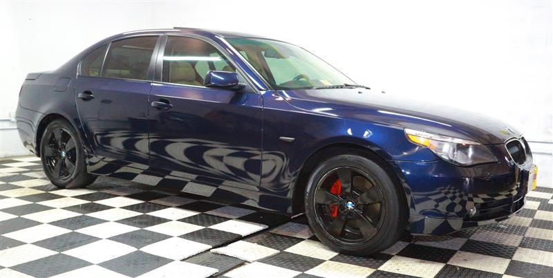
2012 BMW 528xi
ENGINE Fuel System Operating Fluids
Fuel System Operating Fluids
1.0 FUELS FOR GASOLINE ENGINES
Use only unleaded gasoline in vehicles equipped with a catalytic converter.
Fuels containing up to and including 10% of ethanol or other oxygenates with up to 2.8% oxygen by weight, that is, 15% MTBE (methyl tertiary butyl ether) or 3% methanol plus an equivalent amount of co-solvent, will not void the applicable warranties with respect to defects in materials or workmanship.
Although, usage of such alcohol fuel blends may result in driveability, starting, and stalling problems due to reduced volatility and lower energy content of the fuel. Those driveability problems may be especially evident under certain environmental conditions, such as: high or low ambient temperatures and high altitude.
Only specially adapted vehicles (FFV – Flexible Fuel Vehicles) can run on high alcohol fuel blends. BMW, for the various technical and environmental reasons explained below, does not offer FFV models.
Usage of E85, or any other high alcohol content blend (e. g. E30) in BMW vehicles, will cause various driveability complaints (cold start problems, stalling, reduced performance, poor fuel economy, etc.), may cause
excessive emissions, and may cause irreversible damage to engine, emission control and fuel delivery systems due to incompatibility of materials with alcohols.
GENERAL NOTES REGARDING E85 FUEL
E85 fuel contains 85% (by volume) of ethanol and 15% of gasoline. Ethanol can be produced chemically from ethylene or biologically from grains, agricultural wastes, or any organic material containing starch or sugar. In the US, ethanol is mainly produced from corn and is classified as a renewable fuel. Similar to gasoline, ethanol contains hydrogen and carbon; with additional oxygen molecules build into its chemical chain. This chemical structure makes ethanol’s burning process slightly cleaner compared to the gasoline (lower tailpipe emissions).
On the other hand, due to lower carbon content, ethanol provides 27% less energy (for identical volume) then gasoline, resulting in the reduced fuel economy of E85 vehicles (approximately 22% higher consumption).
Increased fuel consumption requires the appropriately enlarged fuel tank capacities (usually 30% increase), and the specific DME calibrations for the E85 lower Stoichiometric air/fuel ratio (10 compared to 14.7 for gasoline engines).
E85 fuel volatility is typically lower then gasoline (RVP 6-10 psi, compared to 8-15 psi for gasoline). Lower fuel volatility will reduce vehicle evaporative emissions, but it may cause cold starting problems especially with lower ambient temperatures.
Under certain environmental conditions, mainly lower ambient temperatures, ethanol separates from gasoline/alcohol mixture and absorbs water.
…