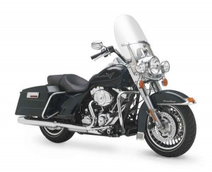
1984-1998 Harley Davidson 1340 FLH/FLT/FXR All Models Motorcycle Workshop Repair & Service Manual (940 Pages, Searchable, Printable, Bookmarked, iPad-ready PDF)
Complete digital workshop service and repair manual written for the Harley Davidson 1340 FLH/FLT/FXR All Models Motorcycle; Production model years: 1984 1985 1986 1987 1988 1989 1990 1991 1992 1993 1994 1995 1996 1997 1998. All styles covered (all models, and engines). It is in the cross-platform PDF document format so that it works like a charm on all kinds of devices.
This QUALITY manual is 100% COMPLETE and INTACT, no MISSING/CORRUPT pages/sections to freak you out! Buy from responsible seller and get INSTANT DOWNLOAD now without wasting your hard-owned money on uncertainty or surprise; this manual is exactly as described.
PRODUCT DETAILS:
Total Pages: 940 pages
File Format: PDF (Windows & Mac & Linux)
Language: English
Delivery: instant download link displayed on checkout page & emailed to you after payment
Protection: DRM-free; without any restriction
Printable: Yes
Models Covered:
FLHR Road King 1995-1998
FLHR-I Road King 1996-1997
FLHRC-I Road King 1998
FLHS ELECTRA GLIDE SPORT 1988-1993
FLHT ELECTRA GLIDE 1995-1998
FLHTC ELECTRA GLIDE CLASSIC & ANNIVERSARY 1984-1998
FLHTC-I Electra Glide Classic 1996-1998
FLHTC-U Electra Glide Classic-Ultra & Anniversary 1989-1997
FLHTC-UI Electra Glide Classic-Ultra & Anniversary 1996-1998
FLTC Tour Glide 1984-1991
FLTC-U Tour Glide-Ultra Classic 1989-1995
FLTC-UI Tour Glide-Ultra Classic 1996
FLTR Road Glide 1998
FLTR-I Road Glide 1998
FXEF Fat Bob 1985
FXLR Low Rider, Custom & Anniversary 1987-1994
FXR Super Glide 1986-1994
FXR2 & FXR3* Super Glide (*Ltd edition 1999 Only) 1999
FXRD Super Glide Grand Touring 1986
FXRS Low Rider & Convertible 1984-1992
FXRS-Con Low Rider-Convertible 1991-1993
FXRS-SP Low Rider-Sport Edition 1988-1993
FXRT Sport Glide 1984-1992
FXSB Low Rider 1985
FXWG Wide Glide 1985-1986
This COMPLETE official full workshop service repair manual includes:
* Detailed sub-steps expand on repair procedure information
* Notes, cautions and warnings throughout each chapter pinpoint critical information.
* Numbered instructions guide you through every repair procedure step by step.
* Bold figure number help you quickly match illustrations with instructions.
* Detailed illustrations, drawings and photos guide you through every procedure.
* Enlarged inset helps you identify and examine parts in detail.
* Numbered table of contents easy to use so that you can find the information you need fast.
* This manual also makes it easy to diagnose and repair problems with your machines electrical system.
* Troubleshooting and electrical service procedures are combined with detailed wiring diagrams for ease of use.
* COMPLETE, Absolutely No Missing Pages!
* Official Service INFORMATION You Can Count On!
* Customer Satisfaction GUARANTEED!
EXCERPT (1984-1998 Harley Davidson 1340 FLH/FLT/FXR All Models Motorbike Service/Repair Manual):
1. Remove the clutch as described in this chapter. Remove the clutch shell assembly from the primary drive chain.
2. Remove the snap ring (Figure 105) from the clutch hub groove.
3. Position the clutch hub and shell with the primary chain sprocket side facing up.
4. Support the clutch hub and clutch shell in a press (Figure 106).
5. Place a suitable size arbor in the clutch hub surface and press the clutch hub (A, Figure 107) out of the bearing.
6. Remove the clutch shell from the press (B, Figure 107).
7. On the inner surface of the clutch shell, remove the bearing retaining snap ring (Figure 108) from the groove in the middle of the clutch shell.
Installation
1. Install the flanges onto the correct side of the induction module with the slotted hole at the top. Refer to the marks made during removal. Install new seals onto the induction module.
2. Carefully install the induction module and fuel line assembly past the horn bracket on the cylinder head ports. Slide the induction module into place and onto the upper two 1/2-in. hex bolts.
3. Connect both throttle cables to the induction module as described in this chapter.
4. On models so equipped, connect the cruise control cable from the induction module as described in this section.
5. Align the mounting flanges and install the two lower bolts by hand. Use the same tool setup used to loosen the bolts. Do not tighten the bolts at this time.
6. Working on the right side of the motorcycle, tighten the Lower two bolts until snug. Do not tighten to the final torque specification at this time. Use the same tool setup used to loosen the bolts.
7. Working on the left side of the motorcycle, tighten the upper two bolts to 71-124 in. Ib. (8-14 Nm).
8. Working on the right side of the motorcycle, tighten the lower two bolts to 71-124 in.-lb. (8-14 Nm).
9. Carefully attach the electrical connector to each fuel injector. Align the grooves in the female connector with the tabs in the male space housing. Push the connector halves together until both latches click.
NOTE :In Step 10, push the electrical connector halves together until the female slot connector is folly engaged with the tabs on the male space housing.