Pages from SEN00291-13 – 12V140E-3 Series Engine Shop Manual
Complete workshop & service manual with electrical wiring diagrams for Komatsu 140 Series Engines (SA12V140-1, SDA12V140-1, SAA12V140-1, SA12V140Z-1, SAA12V140ZE-2, SA6D140E-3, SAA6D140E-3, SDA6D140E-3, SAA12V140E-3). It’s the same service manual used by dealers that guaranteed to be fully functional and intact without any missing page.
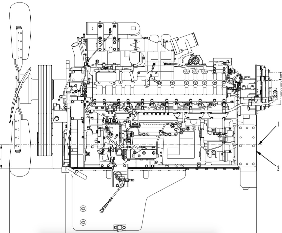
This Komatsu 140 Series Diesel Engines service & repair manual (including maintenance, overhaul, disassembling & assembling, adjustment, tune-up, operation, inspecting, diagnostic & troubleshooting…) is divided into different sections. Each section covers a specific component or system with detailed illustrations. A table of contents is placed at the beginning of each section. Pages are easily found by category, and each page is expandable for great detail. The printer-ready PDF documents work like a charm on all kinds of devices.
FILELIST:
CEBM002601 – SA12V140Z-1 Series Engine Shop Manual.pdf
CEBM002603 – SA12V140Z-1, SAA12V140ZE-2 Series Diesel Engine Shop Manual.pdf
SEBE62120112 – 6D140-1 Series Diesel Engine Shop Manual.pdf
SEBM008612 – 6D140-2 Series Diesel Engine Shop Manual.pdf
SEBM022209 – 140-3 Series Diesel Engine (SA6D140E-3, SAA6D140E-3, SDA6D140E-3) Shop Manual.pdf
SEBM022213 – 140-3 Series Diesel Engine Shop Manual.pdf
SEBM028318 – 12V140-1 Series Diesel Engine (SA12V140-1, SDA12V140-1, SAA12V140-1) Shop Manual.pdf
SEN00074-16 – 140E-5 Series Engine Shop Manual.pdf
SEN00291-13 – 12V140E-3 Series Engine (SAA12V140E-3) Shop Manual.pdf
SEN00291-14 – 12V140E-3 Series Engine Shop Manual.pdf
SEN05641-02 – 140E-6 Series Engine Shop Manual.pdf
EXCERPT:
CONTENTS
01 GENERAL ……………. 01-001
11 STRUCTURE AND FUNCTION ……. 11-001
12 TESTING AND ADJUSTING………. 12-001
13 DISASSEMBLY AND ASSEMBLY ………….. 13-001
14 MAINTENANCE STANDARD…………… 14-001
15 REPAIR AND REPLACEMENT OF PARTS ………. 15-001
…
10 Structure, function and maintenance standard SEN00309-04
(*) The CRI system controls the fuel injection rate and fuel injection timing more properly than the mechanical governor or timer of the conventional fuel injection pump.
(*) For the control of the system, calculations necessary to the ECU are performed from the signals sent from the sensors installed to the engine and machine.
(*) The energizing timing and energizing period of the injector are so controlled that the optimum quantity of fuel will be injected in the optimum timing.
1. Fuel injection rate control function
(*) The fuel injection rate control function is employed instead of the function of the conventional governor. It controls the fuel injection according to the signals of engine speed and accelerator angle so that the fuel injection rate will be most proper.
2. Fuel injection timing control function
(*) The fuel injection timing control function is employed instead of the function of the conventional timer. It controls the fuel injection timing most properly from the engine speed and fuel injection rate.
3. Fuel injection pressure control function (Common rail fuel pressure control function)
(*) The fuel injection control function (common rail fuel pressure control function) controls the fuel discharge rate of the fuel supply pump by measuring the fuel pressure by the common rail fuel pressure sensor and feeding it back to ECU.
(*) This function performs pressure feedback control so that the fuel injection pressure will be the same as the optimum value (command value) set according to the engine speed and fuel injection rate…