Posted on

Case 650K, 750K, 850K Crawler Workshop Repair & Service Manual


Download Link

INSTANT DOWNLOAD (add to cart)


1,360 + 141 pages, bookmarked, Searchable, Printable, high quality PDF
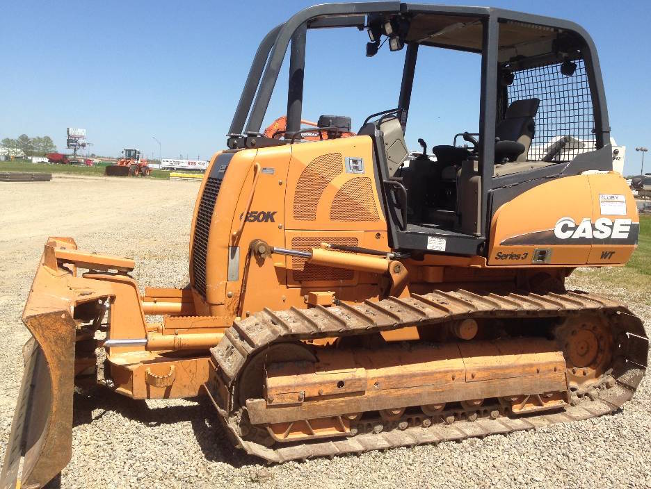
MAKE: Case
MODEL: 650K, 750K, 850K
FORMAT: PDF
PAGES / SIZE: 1,360 (Service Manual) + 141 (Operator’s Manual)

“87364103.pdf”
650K TIER II, 750K TIER II, 850K TIER II Repair Manual
1,360 pages
87364103-NA 2 4/12/2007

6-85641.pdf
650K, 750K, 850K Series Crawler Operator’s Manual
141 pages
6-85641 NA; 12-2005

Complete digital official shop manual contains service, maintenance, and troubleshooting information for the Case 650K, 750K, 850K Crawler. Diagnostic and repair procedures are covered in great detail to repair, maintain, rebuild, refurbish or restore your Case 650K, 750K, 850K like a professional mechanic in local service/repair workshop. This cost-effective quality manual is 100% complete and intact as should be without any missing pages. It is the same factory shop manual used by dealers that guaranteed to be fully functional to save your precious time.

This manual for Case 650K, 750K, 850K Crawler is divided into different sections. Each section covers a specific component or system and, in addition to the standard service procedures, includes disassembling, inspecting, and assembling instructions. A table of contents is placed at the beginning of each section. Pages are easily found by category, and each page is expandable for great detail. It is in the cross-platform PDF document format so that it works like a charm on all kinds of devices. You do not need to be skilled with a computer to use the manual.

EXCERPT:
DISTRIBUTION SYSTEMS- FAULT CODES
4521-Bump up switch stuck on at power up
650K TIER II [CALOOOOOO ~ CAL012143], 750K TIER II [CALOOOOOO ~ CAL003348], 850K TIER II [CALOOOOOO ~ CAL005666]
Cause:
1. Connectors not mated fully, pins not pushed into connector fully, bent pin or broken wire at rear of connector.
2. Button is mechanically stuck.
3. Wiring or switch circuits shorted.
4. Failed Drivetrain Control Module.
Possible failure modes:
1. The Instrument Cluster is indicating that the Maximum Speed setting is increasing, when Bump Up Switch is not being commanded.
Solution:
1. Find out if the fault code is still active, refer to Command Display/service switch – Dynamic description (C.20.F).
Prior to clearing fault codes write down all fault codes, number of occurrences, and engine hours at last occurrence.
A. Turn ignition switch to RUN position to power drivetrain controller.
B. Clear all fault codes from the controller.
C. To check for fault code: Move directional control to neutral, ignition switch to run (engine does not need to be running), move both parking levers to down position, move hand throttle to high idle position, and push directional control to forward position.
D. NOT OK- Fault code 4521 is recorded again. Go to step 2.
E. OK for return to service.
2. Inspect the Bump Up Switch Connection.
A. Turn ignition switch and master disconnect off.
B. Check for button mechanically stuck.
C. Clear buttons of any foreign debris.
D. NOT OK- Return to Step 1 to confirm elimination of fault.
E. OK – Go to Step 3.
3. Check for open circuit in the Bump Up Switch.
A Disconnect the Bump Up Switch Connector.
B. Check wiring and connector for Bump Up Switch.
C. NOT OK- Replace handle and button. and return to Step 1 to confirm elimination of fault.
D. OK- Go to Step 4.
4. Replace the Drivetrain Control Module.
A Remove and replace Drivetrain Control Module. refer to Electrical control -Remove (C.20.F) and Electrical control -Install (C.20.F).
B. Write symptom on failed Drivetrain Control Module.
C. Install program with Electronic Service Tool (EST) and calibrate the system.
4522-Bump down switch stuck on at power up
650K TIER II [CAL012200 -], 750K TIER II [CAL003400-], 850K TIER II [CAL005700-]
Cause:
1. Connectors not mated fully, pins not pushed into connector fully, bent pin or broken wire at rear of connector.
2. Button is mechanically stuck.
3. Wiring or switch circuits shorted.
4. Failed Drivetrain Control Module.
Possible failure modes:
1. The Instrument Cluster is indicating that the Maximum Speed setting is increasing, when Bump Down Switch is not being commanded.
Solution:
1. Find out if the fault code is still active, refer to Command Display/service switch -Dynamic description (C.20.F).
Prior to clearing fault codes write down all fault codes, number of occurrences, and engine hours at last occurrence.
A. Turn ignition switch to RUN position to power drivetrain controller.
B. Clear all fault codes from the controller.
C. To check for fault code: Move directional control to neutral, ignition switch to run (engine does not need to be running), move both parking levers to down position, move hand throttle to high idle position, and push directional control to forward position.
D. NOT OK- Fault code 4522 is recorded again. Go to step 2.
E. OK for return to service.
2. Inspect the Bump Down Switch Connection.
A. Turn ignition switch and master disconnect off.
B. Check for button mechanically stuck.
C. Clear buttons of any foreign debris.
D. NOT OK- Return to Step 1 to confirm elimination of fault.
E. OK – Go to Step 3.
3. Check for open circuit in the Bump Down Switch.
A. Disconnect the Bump Down Switch Connector.
B. Check wiring and connector for Bump Down Switch.
C. NOT OK- Replace handle and button, and return to Step 1 to confirm elimination of fault.
D. OK-Go to Step 4.
4. Replace the FNR joystick.
A. Return to Step 1 to confirm elimination of fault.
B. NOT OK-Go to Step 5.
5. Turn ignition switch and master disconnect OFF, disconnect controller Connector C1, turn master disconnect ON.

A. Check for continuity from pins 2 and 28 to ground.
B. NOT OK- Repair ground circuit. Return to Step 1 to confirm elimination of fault.
C. OK-Go to Step 6.
6. Turn the ignition switch ON.
A. Check for power at pins 1 and 27 to ground.
B. Check fuse #9 and fuse #3.
C. Check circuit from pins 1 and 27 Connector C1 to pin 16 Connector C4, form pin 16 Connector M10 to pin 9A Connector M2.
D. NOT OK- Repair power circuit. Return to Step 1 to confirm elimination of fault.
E. OK-Go to Step 7.
7. At Connector C1.

Posted on

Case 621E Wheel loader Workshop Repair & Service Manual


Download Link

INSTANT DOWNLOAD (add to cart)


936 pages, bookmarked, Searchable, Printable, high quality PDF

84243974 – 621E TIER 3 Wheel loader Service Manual.pdf
Revised June 2009
Issued September 2007

Complete digital official shop manual contains service, maintenance, and troubleshooting information for the Case 621E Wheel loader. Diagnostic and repair procedures are covered in great detail to repair, maintain, rebuild, refurbish or restore your Case 621E Wheel loader like a professional mechanic in local service/repair workshop. This cost-effective quality manual is 100% complete and intact as should be without any missing pages. It is the same factory shop manual used by dealers that guaranteed to be fully functional to save your precious time.

This manual for Case 621E Wheel loader is divided into different sections. Each section covers a specific component or system and, in addition to the standard service procedures, includes disassembling, inspecting, and assembling instructions. A table of contents is placed at the beginning of each section. Pages are easily found by category, and each page is expandable for great detail. It is in the cross-platform PDF document format so that it works like a charm on all kinds of devices. You do not need to be skilled with a computer to use the manual.

EXCERPT:
621 E Wheel Loader
Service Manual 84243974
(Replaces 87634756)
Table of Contents
General
Section Index – General
Standard Torque Specifications
Fluids and Lubricants
Metric Conversion Chart
Engines
Section Index – Engines
Description
Engine and Radiator Removal and Installation
Stall Tests
After Cooler
For Engine Repair, See the Engine Service Manual
Fuel System
Section Index- Fuel System
For Fuel System Repair, See the Engine Service Manual
Electrical
Section Index- Electrical
Removal and Installation of Starter and Alternator
Electrical Specifications and Troubleshooting
Batteries
Instrument Cluster
Steering
Section Index – Steering
Removal and Installation of Steering Components
Steering Specifications, Pressure Checks, and Troubleshooting
Steering Cylinders
Center Pivot
Auxiliary Steering Motor and Pump
Joystick Steering
Power Train
Section Index – Power Train
Removal and Installation of Power Train Components
Transmission Specifications, Pressure Checks, and Troubleshooting
Transmission
Front Axle
Rear Axle
Rear Axle, Serial Number N8F203848 and After
Drive Shafts, Center Bearing, and Universal Joints
Wheels and Tires
Transmission Control Valve
Brakes
Section Index – Brakes
Removal and Installation of Brake Components
Hydraulic Brake Troubleshooting
Brake Pump
Brake Accumulators
Parking Brake
Hydraulics
Section Index- Hydraulics
How to Read Hydraulic Schematics
Removal and Installation of Hydraulic Components
Hydraulic Specifications, Troubleshooting, and Pressure Checks
Cleaning the Hydraulic System
Hydraulic Pump
Loader Control Valve
Cylinders
Coupler Solenoid Locking Valve
Ride Control Accumulator
Ride Control Valve
Section Index – Mounted Equipment
Air Conditioning Troubleshooting and System Checks For Systems with HFC-
134a Refrigerant
Air Conditioner System Service
Removal And Installation Of Air Conditioning And Heater Components
Loader
Roll Over Protective Structure (ROPS), Cab Structural Frame (CSF)
Cab Glass Installation
Electrical Schematic Foldouts and Hydraulic Schematic Foldout

The instrument cluster monitors a number of functions and can be tailored to fit the operator’s preferences. The instrument cluster not only monitors machine functions, it warns the operator when caution is needed due to a possible malfunction and when immediate action is needed due to a possible critical malfunction. When the machine is started, the instrument cluster will perform the following self-test:
Self-Test
1. Turn the ignition (key) switch to the ON position.
2. The instrument cluster will automatically check each monitored system.
3. All LED’s (Light Emitting Diodes) will illuminate for 2- 3 seconds.
4. Four gauges will energize for 2- 3 seconds.
5. The warning alarm will sound for 2 – 3 seconds.
6. If there is an open circuit between a sensor and the instrument cluster, the LED will flash and the warning alarm will sound for 5 seconds.
7. If there were no faults detected during the check, all monitored systems will return to normal operation.
8. If only some of the LEDs illuminate, replace the instrument cluster.
9. If the LEDs illuminate, but the warning alarm does not sound, see section 4002 and test the alarm circuit.
10. If the warning alarm sounds but the LEDs do not illuminate, if no power is present at buzzer,
replace the instrument cluster, if power is present at the buzzer, replace the buzzer.
11. If the warning alarm does not sound and the LEDs do not illuminate on the instrument cluster, do the following steps to test the power circuit:
Power Circuit Test
A. Check fuse ECA-F3. If the fuse is bad, replace the fuse and repeat Self-Test. If the fuse is good, go to next step.
B. Check wire 19EA for continuity.
Repair/replace the wire as required. If continuity is found go to next step.
C. Check power relay module A for proper operation, see Section 4002. If the power relay module checks good, go to next step.
D. Check the ignition switch for proper operation, see Section 4002. If the ignition switch checks good, go to next step.
E. Check fuse ECC-F5. If the fuse is bad, replace the fuse.

Posted on

Case 621D Wheel Loader Factory Service & Shop Manual


Download Link

INSTANT DOWNLOAD (add to cart)


5,500+ pages, bookmarked, Searchable, Printable, high quality PDF

6-42965 – 621D Loader Service Manual.pdf – 1,064 pages
6-42961 – Cargadora 621D Manual de mantenimiento (ES).pdf – 788 pages
6-42961 – Caricatore Case 621D Manuale di manutenzione (IT).pdf -786 pages
6-42962 – 621D Lader Wartungsanleitung (DE).pdf – 988 pages
6-42962 – Chargeuse Case 621D Manuel d’entretien (FR).pdf – 986 pages
6-42964 – Case 621D Loader Service Manual.pdf – 988 pages
621D Loader Electrical Hydraulic Foldout.pdf
621D Loader Schematic.pdf

Complete workshop & service manual with electrical wiring diagrams for Case 621D Wheel Loader. It’s the same service manual used by dealers that guaranteed to be fully functional and intact without any missing page.

This Case 621D Wheeled Loader service & repair manual (including maintenance, overhaul, disassembling & assembling, adjustment, tune-up, operation, inspecting, diagnostic & troubleshooting…) is divided into different sections. Each section covers a specific component or system with detailed illustrations. A table of contents is placed at the beginning of each section. Pages are easily found by category, and each page is expandable for great detail. The printer-ready PDF documents work like a charm on all kinds of devices.

EXCERPT:
STEERING CONTROL VALVE
Removal
1. Remove the left, right, and front cab skirts, located under the cab or canopy.
2. Remove all dirt and grease from the steering control valve (5) and the area around the steering control valve (5), refer to the illustration on page 5.
3. Remove the fill cap for the hydraulic reservoir.
4. Fasten identification tags to the hoses at the steering control valve (5).
5. Disconnect the hoses from the fittings in the steering control valve (5).
6. Cap or plug the fittings and hoses.
7. Turn the steering wheel as required for access to the cap screw (1) that holds the steering column shaft (6) of the steering control valve (5) in the coupling (2).
8. Remove the cap screw (1) that holds the steering column shaft (6) of the steering control valve (5) in the coupling (2).
9. Hold the steering control valve (5) in position and remove the bolts (7), washers (3), and steering isolator mounts (4) that fasten the base plate (11) and steering control valve (5) to the bottom of the pedestal (12).
10. Remove the steering control valve (5) and base plate (11) from the machine.
11. Remove the bolts (9) and lock washers (1 0) that fasten the base plate (11) to the steering control
valve (5).
12. Remove the base plate (11) and seals (8) from the steering control valve (5).

Posted on

Case 621C/721C Loader Factory Service & Shop Manual


Download Link

INSTANT DOWNLOAD (add to cart)


1,000+ pages, bookmarked, Searchable, Printable, high quality PDF

“Case 621C/721C Loader Service Manual” – 824 pages
“6-30480NA – Case 721C Wheel Loader Operator’s Manual” – 288 pages
“6-1231.pdf – Case 621C-721C Loaders Operator’s Manual” – 281 pages
“721C EWD & Hydraulic Schematic.pdf”

Complete workshop & service manual with electrical wiring diagrams for Case 621C/721C Loader. It’s the same service manual used by dealers that guaranteed to be fully functional and intact without any missing page.

This Case 621C/721C Wheeled Loader service & repair manual (including maintenance, overhaul, disassembling & assembling, adjustment, tune-up, operation, inspecting, diagnostic & troubleshooting…) is divided into different sections. Each section covers a specific component or system with detailed illustrations. A table of contents is placed at the beginning of each section. Pages are easily found by category, and each page is expandable for great detail. The printer-ready PDF documents work like a charm on all kinds of devices.

EXCERPT:
INFORMATION AND DIAGNOSTIC CENTER
Many of the machine functions can be displayed on the Programmable Information Center. It can be programmed to display all functions, or only the functions important to the operator. The following functions can be displayed on the Information Center, refer to Figure 2:
FIGURE 2. INFORMATION CENTER AND TRANSMISSION DISPLAY
1. DIRECTION (F-N-R) 4. REQUESTED GEAR (1, 2, 3, 4)
2. TRANSMISSION DISPLAY 5. ACTUAL GEAR BARS
3. DISPLAY CENTER 6. TRANSMISSION MODE (A OR BLANK)
Hourmeter
The hourmeter displays the accumulated running time of the engine in hours and tenths of an hour with an “hour glass” symbol.
Tachometer
The tachometer displays the engine speed in revolutions per minute along with a “r/min” symbol.
Speedometer
The speedometer displays the ground speed in either kilometers per hour (km/h) or miles per hour (mph) along with either a “km/h” or “mph” symbol.
Engine Coolant Temperature
Displays the engine coolant temperature in Celsius with the engine coolant temperature bar graph flashing. See page 10 for a detailed description of the bar graph function.
Engine Oil Pressure
Displays the engine oil pressure in kilopascals (kPa) with the engine oil pressure bar graph flashing. See page 10 for a detailed description of the bar graph function.
Fuel Level
Displays the fuel level in percent remaining in the tank with the fuel level bar graph flashing. See page 10 for a detailed description of the bar graph function.

Posted on

Case 621B, 721B Loaders Workshop Repair & Service Manual


Download Link

INSTANT DOWNLOAD (add to cart)


Case 621B, 721B Loaders Workshop Repair & Service Manual

1,860 pages, bookmarked, Searchable, Printable, high quality PDF

621B, 721B Loaders Service Manual.pdf
621 B 6T-590; 721 B 6T-830

Complete digital official shop manual contains service, maintenance, and troubleshooting information for the Case 621B, 721B Loaders. Diagnostic and repair procedures are covered in great detail to repair, maintain, rebuild, refurbish or restore your Case 621B, 721B Loaders like a professional mechanic in local service/repair workshop. This cost-effective quality manual is 100% complete and intact as should be without any missing pages. It is the same factory shop manual used by dealers that guaranteed to be fully functional to save your precious time.

This manual for Case 621B, 721B Loaders is divided into different sections. Each section covers a specific component or system and, in addition to the standard service procedures, includes disassembling, inspecting, and assembling instructions. A table of contents is placed at the beginning of each section. Pages are easily found by category, and each page is expandable for great detail. It is in the cross-platform PDF document format so that it works like a charm on all kinds of devices. You do not need to be skilled with a computer to use the manual.

EXCERPT:

STEP 80
Measure the cylinder sleeve bore for taper as follows:
1. Measure the bore parallel to the crankshaft at the top end of the ring travel zone.
2. Measure the bore in the same position at the bottom end of the ring travel zone.
3. Measure the bore at right angles to the crankshaft at the top end of the ring travel zone.
4. Measure the bore in the same position at the bottom end of the travel zone.
Compare the results of the measurements (1) and (3) with (2) and (4), to find out if the bore has taper. To measure use a inside micrometer, bore gauge or taper gauge. If the taper is more than 0.04 mm, the cylinder sleeve must be replaced.
STEP 81
Measure the cylinder sleeve bores for out-of-round as follows:
1. Measure the bore parallel to the crankshaft at the top end of the ring travel.
2. Measure the bore in the same position at the bottom end of the ring travel.
3. Measure the bore at right angles to the crankshaft at the top end of the ring travel.
4. Measure the bore in the same position at the bottom end of the ring travel.
Compare the measurements (1) and (3) to find the outof-round wear at the top end of the bore.
Compare the measurements (2) and (4) to find the outof-round wear at the bottom of the bore.
If out-of-round is more than 0.04 mm, the cylinder sleeve must be replaced.
Removing the Cylinder Sleeves
IMPORTANT: Cover the crankshaft journals with a clean cloth. Foreign material from the cylinder sleeve or the cylinder block will cause damage to the crankshaft.
STEP 82
Install a sleeve puller to remove the cylinder sleeve. Position the puller in the sleeve. Make sure that the jaws of the puller do not contact the four block lugs. Tighten the lock bar against the cylinder sleeve.
IMPORTANT: Make sure that the jaws of the sleeve puller do not contact the block lugs.
STEP 83
Carefully turn the bearing nut until the cylinder sleeve is loose from the cylinder block.
STEP 84
Remove the cylinder sleeve from the cylinder block.
Remove the a-ring from the cylinder sleeve.