Posted on

Komatsu Dump Truck HD205 Factory Service & Shop Manual

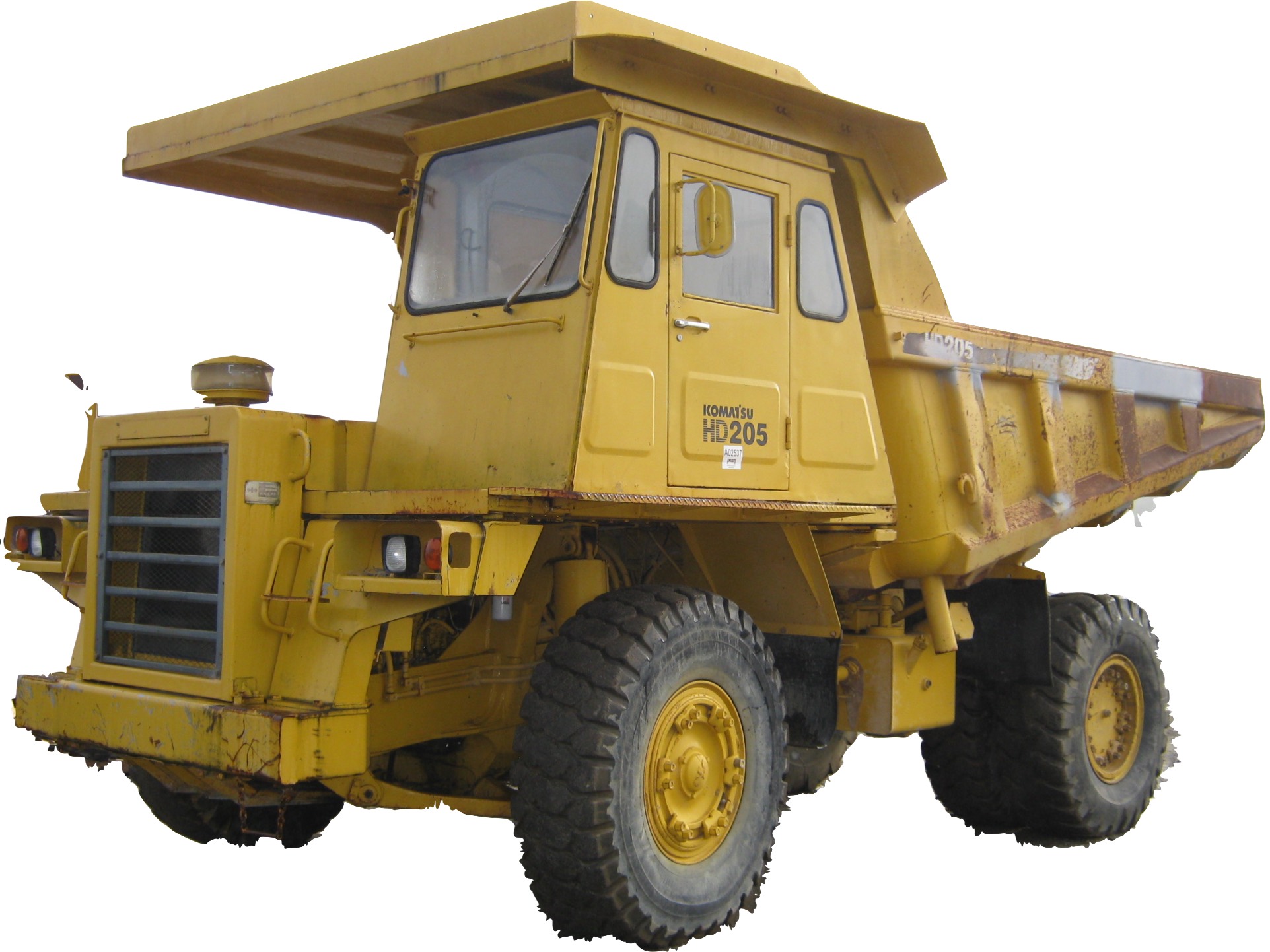
Pages from SEBM05670302 – Dump Truck HD205-3 Shop Manual


INSTANT DOWNLOAD


Complete workshop & service manual with electrical wiring diagrams for Komatsu Dump Truck HD205. It’s the same service manual used by dealers that guaranteed to be fully functional and intact without any missing page.

This Dump Truck HD205-3 service & repair manual (including maintenance, overhaul, disassembling & assembling, adjustment, tune-up, operation, inspecting, diagnostic & troubleshooting…) is divided into different sections. Each section covers a specific component or system with detailed illustrations. A table of contents is placed at the beginning of each section. Pages are easily found by category, and each page is expandable for great detail. The printer-ready PDF documents work like a charm on all kinds of devices.

SEBM05670302 – Dump Truck HD205-3 Shop Manual

EXCERPT:
TABLE OF CONTENTS
10 ENGINE
11 STRUCTURE AND FUNCTION . . . . 11 -1
12 TESTING AND ADJUSTING . . . . 12-1
13 DISASSEMBLY AND ASSEMBLY . . . . 13-1
20 POWER TRAIN
21 STRUCTURE AND FUNCTION . . . . 21-1
22 TESTING AND ADJUSTING . . . . 22-1
23 DISASSEMBLY AND ASSEMBLY. . . . 23-1
24 MAINTENANCE STANDARD . . . . 24-1
40 UNDERCARRIAGE
41 STRCTURE AND FUNCTION . . . 41-1
42 TESTING AND ADJUSTING . . . . 42-1
43 DISASSEMBLY AND ASSEMBLY . . . 43-1
44 MAINTENANCE STANDARD . . . . 44-1
50 AIR SYSTEM
51 STRCTURE AND FUNCTION . . . 51-1
52 TESTING AND ADJUSTING . . . . 52-1
53 DISASSEMBLY AND ASSEMBLY . . . . 53-1
54 MAINTENANCE STANDARD . . . . 54-1
60 HYDRAULIC SYSTEM
61 STRUCTURE AND FUNCTION . . . . 61-1
62 TESTING AND ADJUSTING . . . . 62-1
63 DISASSEMBLY AND ASSEMBLY . . . . 63-1
64 MAINTENANCE STANDARD . . . . 64-1
70 WORK EQUIPMENT
71 STRUCTURE AND FUNCTION . . . . 71-1
73 DISASSEMBLY AND ASSEMBLY . . . . 73-1
74 MAINTENANCE STANDARD . . . . 74-1
80 ELECTRICAL SYSTEM
81 STRUCTURE AND FUNCTION . . . . 81-1
82 TESTING AND ADJUSTING . . . . 82-1

SUSPENSION SYSTEM
The chassis suspension permits the truck to travel at high speed, without pitching or bouching even on rough terrain, and with high operational safety.
The front suspension on the HD205 is a hydro-pneumatic suspension system, while the rear suspension is a leaf spring type.
In this hydro-pneumatic suspension system for front suspension, the oil and nitrogen gas are sealed in the suspension cylinders.
When a shock force is imparted to the chassis from the ground when traveling, the oil and nitrogen gas service as the shock absorbing means by their compression and expansion characteristics.


INSTANT DOWNLOAD


Posted on

Komatsu Articulated Dump Truck HA250, HA270 Factory Service & Shop Manual

Pages from SEBMHA250104 – Articulated Dump Truck HA250-1, HA250-3, HA270-1, HA270-3 Shop Manual


INSTANT DOWNLOAD


Complete workshop & service manual with electrical wiring diagrams for Komatsu Articulated Dump Truck HA250-1, HA250-3, HA270-1, HA270-3. It’s the same service manual used by dealers that guaranteed to be fully functional and intact without any missing page.

This Komatsu Articulated Dump Truck HA250-1, HA250-3, HA270-1, HA270-3 service & repair manual (including maintenance, overhaul, disassembling & assembling, adjustment, tune-up, operation, inspecting, diagnostic & troubleshooting…) is divided into different sections. Each section covers a specific component or system with detailed illustrations. A table of contents is placed at the beginning of each section. Pages are easily found by category, and each page is expandable for great detail. The printer-ready PDF documents work like a charm on all kinds of devices.

SEBMHA250104 – Articulated Dump Truck HA250-1 & HA270-1 Shop Manual.pdf
SEBMHA250104 – Articulated Dump Truck HA250-1, HA250-3, HA270-1, HA270-3 Shop Manual.pdf
XEAMM00100 – Articulated Dump Truck HA250-3, HA270-3 Operation & Maintenance Manual.pdf

EXCERPT:
GOVERNOR
The governor controls pressure level in the wet reservoir of the brake system. The governor controls the relief mechanism of the compressor so that it stops charging when max. working pressure has been reached and starts charging when the pressure has dropped below minimum working pressure.
Compressor charging
Compressed air flows through the pipe from the wet reservoir through inlet 1 to the space above piston 5. When air pressure increases the piston is pressed down and compresses spring 8. Pressure rod 7 and vent pipe 6 cannot move down.
Compressor relieved
When piston 5 is pressed down, vent pipe 6 prevents valve disc 4 from following. Air passes past the valve disc out through the hole in the piston and on through outlet 2 to the compressor relief mechanism which opens intake valves whereby compression is interrupted.
Relief, final phase
The cylinder diameter at the lower 0 ring is larger than that at upper. Air now presses on top of the piston as well as the surface at the lower O ring.
Pressure required to retain the piston therefore becomes less than that which originally pressed down the piston.


INSTANT DOWNLOAD


Posted on

Komatsu Dump Truck 960E-1, 960E-2, 960E-2K, 960E-2KT Workshop Repair & Service Manual

Komatsu 960E-2 Dump Trucks


INSTANT DOWNLOAD


Complete digital official shop manual contains service, maintenance, and troubleshooting information for the Komatsu Dump Truck 960E-1, 960E-2, 960E-2K, 960E-2KT. Diagnostic and repair procedures are covered in great detail to repair, maintain, rebuild, refurbish or restore your trucks like a professional mechanic in local service/repair workshop. This cost-effective quality manual is 100% complete and intact as should be without any missing pages. It is the same factory shop manual used by dealers that guaranteed to be fully functional to save your precious time.

This manual for Komatsu Komatsu Dump Truck 960E-1, 960E-2, 960E-2K, 960E-2KT is divided into different sections. Each section covers a specific component or system and, in addition to the standard service procedures, includes disassembling, inspecting, and assembling instructions. A table of contents is placed at the beginning of each section. Pages are easily found by category, and each page is expandable for great detail. It is in the cross-platform PDF document format so that it works like a charm on all kinds of devices. You do not need to be skilled with a computer to use the manual.

CEAM022100 – Dump Truck 960E-1K Operation & Maintenance Manual.pdf
CEAM022901 – Dump Truck 960E-1 Operation & Maintenance Manual.pdf
CEAM026101 – Dump Truck 960E-2 Operation & Maintenance Manual.pdf
CEAM026401 – Dump Truck 960E-2K Operation & Maintenance Manual.pdf
CEAW005502 – Dump Truck 960E-1 Field Assembly Manual.pdf
CEAW005503 – Dump Truck 960E-1 Field Assembly Manual.pdf
CEAW006500 – Dump Truck 960E-1K Field Assembly Manual.pdf
CEAW006502 – Dump Truck 960E-2K Field Assembly Manual.pdf
CEAW007302 – Dump Truck 960E-2 Field Assembly Manual.pdf
CEBM021300 – Dump Truck 960E-1 Shop Manual.pdf
CEBM021304 – Dump Truck 960E-1 Shop Manual.pdf
CEBM022602 – Dump Truck 960E-1 Shop Manual.pdf
CEBM023802 – Dump Truck 960E-1 Shop Manual.pdf
CEBM025901 – Dump Truck 960E-2 Shop Manual.pdf
CEBM026301 – Dump Truck 960E-2K Shop Manual.pdf
CEBM028400 – Dump Truck 960E-2KT Shop Manual.pdf

EXCERPT:

50 Disassembly and assembly
Removal and installation of rear axle
Removal
1. Park the truck on firm, level ground and chock the rear wheels to prevent truck movement.
2. Shut down the truck. For the proper shutdown procedure, refer to Index and foreword section Operating instructions.
3. Remove the dump body. Refer to Disassembly and assembly section Body and structures.
4. Block up the truck and remove the rear wheels.
Refer to “Removal and installation of rear wheel”.
5. Loosen the hose clamps and disconnect axle air blower hose (1, Figure 50-17) from wheel motor cooling air duct (2).
6. Install vacuum pump kit (XB0887) on the hydraulic tank to prevent the loss of oil when disconnecting hydraulic lines.
7. Remove the drain plugs at the bottom of the rear brake assemblies. Allow the oil to drain from the brakes into a suitable container.
FIGURE 50-17. REAR AXLE HOUSING
1. Axle Air Blower Hose
2. Wheel Motor Cooling Air Duct
3. Power Cable Mount
4. Hydraulic Hose Manifold
8. Disconnect and unclamp the hoses at hydraulic hose manifold (4) on the left side of the rear axle housing. Cap the fittings and plug the hoses to prevent contamination.
9. Remove the power cable grips at power cable mount (3) on the right side of the rear axle housing. Slide the cable grips forward on the cables.
10. Disconnect the brake cooling lines at each brake assembly back plate. Disconnect the brake apply lines. Cap and plug all openings.
11. After all hydraulic lines have been reconnected, turn off the vacuum pump and remove the vacuum pump from the hydraulic tank.
12. Remove the clamps that secure the brake hoses to the spindles.
NOTE: For access to components inside the rear axle housing, the rear hatch can be opened and the top cover can be removed.
13. Disconnect and cap the parking brake supply lines to the parking brake on each wheel motor.
14. Remove the wheel motor cooling air duct from between the wheel motors.
15. Disconnect all wheel motor power cables and electrical harnesses at their terminals. Remove the cable clamps and pull the cables and harnesses from the rear axle housing.
16. Disconnect and unclamp any electrical harnesses that are attached to the rear axle housing as necessary.
17. Remove all automatic lubrication system hoses and clamps that are attached to the rear axle housing. Secure the hoses to the frame to prevent interference during rear axle housing removal.
18. Remove the wheel motors. Refer to “Removal and installation of wheel motor”.
19. Remove the rear suspensions. Refer to
Disassembly and assembly section
Suspensions.
20. Remove the anti-sway bar. Refer to “Removal and installation of anti-sway bar”.
21. Remove the pivot pin. Refer to “Removal and installation of pivot pin”.
22. Attach an overhead hoist or crane to the lifting eyes on the rear axle housing and move it away from the rear of the frame.


INSTANT DOWNLOAD


Posted on

Porsche Boxster/Cayman 1996-2012 Workshop Repair & Service Manual

Porsche 986-987 1996-2012

MPSCBOCAOPES.PDF
Price: $29.99 USD

Complete digital official shop manual contains service, maintenance, and troubleshooting information for the 1996-2012 Porsche Boxster/Cayman (986, 987). Diagnostic and repair procedures are covered in great detail to repair, maintain, rebuild, refurbish or restore your vehicle like a professional mechanic in local service/repair workshop. This cost-effective quality manual is 100% complete and intact as should be without any missing pages. It is the same factory shop manual used by dealers that guaranteed to be fully functional to save your precious time.

This manual for 1996-2012 Porsche Boxster/Cayman (986, 987) is divided into different sections. Each section covers a specific component or system and, in addition to the standard service procedures, includes disassembling, inspecting, and assembling instructions. A table of contents is placed at the beginning of each section. Pages are easily found by category, and each page is expandable for great detail. It is in the cross-platform PDF document format so that it works like a charm on all kinds of devices. You do not need to be skilled with a computer to use the manual.

EXCERPT:
HBA diagnosis – Boxster

System description

The HBA system is installed in vehicles with Litronic headlights.

The HBA system consists of the following components:
Angle sensor for HBA, rear, with linkage
Angle sensor for HBA, front, with linkage
One stepper motor in each headlight (servomotor for HBA)
Control module

Braking or celebration, as well as loading, changes the inclination of the vehicle and therefore the headlight range. The HBA system already reacts to the above driving conditions when the dipped beam is switched on, preventing oncoming traffic from being dazzled. Furthermore, the system ensures an ideal headlight range for the driver in all driving situations.

The sensor at the front and rear axles measure the vehicle inclination and forwards this value as sensor sign is to the control module, which carries out the further processing of the signals. If it should be necessary to change the headlight range, the stepper motors in the headlights are adjusted to he appropriate position. The HBA system also functions with the high-beam setting.

Boxster Seat upholsteries, cover
Installation overview of seat covering components
1 Fitting seat covering on the foam part (seat cushion)
2 Fitting seat covering on the cushion carrier
3 Adhering seat covering on the cushion carrier
4 Fitting seat cushion on the seat frame
5 Fitting cover of seat adjuster
6 Connecting electrical plug connection
Installing covering for front seat

Posted on

Komatsu Dump Truck 930E, 930E-2, 930E-3, 930E-3SE, 930E-4, 930E-4SE Workshop Repair & Service Manual

Komatsu 930E-4, 930E-4SE Dump Trucks


INSTANT DOWNLOAD


Complete digital official shop manual contains service, maintenance, and troubleshooting information for the Komatsu Dump Truck 930E, 930E-2, 930E-3, 930E-3SE, 930E-4, 930E-4SE. Diagnostic and repair procedures are covered in great detail to repair, maintain, rebuild, refurbish or restore your trucks like a professional mechanic in local service/repair workshop. This cost-effective quality manual is 100% complete and intact as should be without any missing pages. It is the same factory shop manual used by dealers that guaranteed to be fully functional to save your precious time.

This manual for Komatsu Dump Truck 930E, 930E-2, 930E-3, 930E-3SE, 930E-4, 930E-4SE is divided into different sections. Each section covers a specific component or system and, in addition to the standard service procedures, includes disassembling, inspecting, and assembling instructions. A table of contents is placed at the beginning of each section. Pages are easily found by category, and each page is expandable for great detail. It is in the cross-platform PDF document format so that it works like a charm on all kinds of devices. You do not need to be skilled with a computer to use the manual.

FILELIST (1.9G PDF):
CEAM006400 – Dump Truck 930E-2 Operation & Maintenance Manual.pdf
CEAM006500 – Dump Truck 930E-2 Operation & Maintenance Manual.pdf
CEAM006600 – Dump Truck 930E-2 Operation & Maintenance Manual.pdf
CEAM006900 – Dump Truck 930E-2 Operation & Maintenance Manual.pdf
CEAM007000 – Dump Truck 930E-2 Operation & Maintenance Manual.pdf
CEAM010001 – Dump Truck 930E-2 Operation & Maintenance Manual.pdf
CEAM010200 – Dump Truck 930E-2 Operation & Maintenance Manual.pdf
CEAM010500 – Dump Truck 930E-2SE Operation & Maintenance Manual.pdf
CEAM011600 – Dump Truck 930E-2 Operation & Maintenance Manual.pdf
CEAM011700 – Dump Truck 930E-2 Operation & Maintenance Manual.pdf
CEAM011900 – Dump Truck 930E-2 Operation & Maintenance Manual.pdf
CEAM012000 – Dump Truck 930E-2 Operation & Maintenance Manual.pdf
CEAM012100 – Dump Truck 930E-2 Operation & Maintenance Manual.pdf
CEAM013500 – Dump Truck 930E-3 Operation & Maintenance Manual.pdf
CEAM014001 – Dump Truck 930E-3SE Operation & Maintenance Manual.pdf
CEAM014600 – Dump Truck 930E-3 Operation & Maintenance Manual.pdf
CEAM015901 – Dump Truck 930E-3 Operation & Maintenance Manual.pdf
CEAM016000 – Dump Truck 930E-3SE Operation & Maintenance Manual.pdf
CEAM017906 – Dump Truck 930E-4 Operation & Maintenance Manual.pdf
CEAM019403 – Dump Truck 930E-4SE Operation & Maintenance Manual.pdf
CEAM019604 – Dump Truck 930E-4 Operation & Maintenance Manual.pdf
CEAM020205 – Dump Truck 930E-4 Operation & Maintenance Manual.pdf
CEAM020305 – Dump Truck 930E-4 Operation & Maintenance Manual.pdf
CEAM020504 – Dump Truck 930E-4SE Operation & Maintenance Manual.pdf
CEAM021005 – Dump Truck 930E-4 Operation & Maintenance Manual.pdf
CEAM021304 – Dump Truck 930E-4SE Operation & Maintenance Manual.pdf
CEAM021405 – Dump Truck 930E-4 Operation & Maintenance Manual.pdf
CEAM022602 – Dump Truck 930E-4 Operation & Maintenance Manual.pdf
CEAM022701 – Dump Truck 930E-4SE Operation & Maintenance Manual.pdf
CEAM024203 – Dump Truck 930E-4 Operation & Maintenance Manual.pdf
CEAM024302 – Dump Truck 930E-4 Operation & Maintenance Manual.pdf
CEAM024503 – Dump Truck 930E-4SE Operation & Maintenance Manual.pdf
CEAM027800 – Dump Truck 930E-4 Operation & Maintenance Manual.pdf
CEAW003900 – Dump Truck 930E-3 Field Assembly Manual.pdf
CEAW004001 – Dump Truck 930E-3SE Field Assembly Manual.pdf
CEAW004600 – Dump Truck 930E-4 Field Assembly Manual.pdf
CEAW005000 – Dump Truck 930E-4SE Field Assembly Manual.pdf
CEAW006103 – Dump Truck 930E-4 Field Assembly Manual.pdf
CEAW006203 – Dump Truck 930E-4SE Field Assembly Manual.pdf
CEAW006600 – Dump Truck 930E-4 Field Assembly Manual.pdf
CEAW006901 – Dump Truck 930E-4 Field Assembly Manual.pdf
CEAW007001 – Dump Truck 930E-4SE Field Assembly Manual.pdf
CEAWD03300 – Dump Truck 930E-2 Field Assembly Manual.pdf
CEBM006402 – Dump Truck 930E-2 Shop Manual.pdf
CEBM006502 – Dump Truck 930E-2 Shop Manual.pdf
CEBM006602 – Dump Truck 930E-2 Shop Manual.pdf
CEBM006902 – Dump Truck 930E-2 Shop Manual.pdf
CEBM007002 – Dump Truck 930E-2 Shop Manual.pdf
CEBM008003 – Dump Truck 930E-2 Shop Manual.pdf
CEBM008400 – Dump Truck 930E-3 Shop Manual.pdf
CEBM008401 – Dump Truck 930E-3 Shop Manual.pdf
CEBM010100 – Dump Truck 930E Shop Manual.pdf
CEBM010200 – Dump Truck 930E Shop Manual.pdf
CEBM010401 – Dump Truck 930E-2 Shop Manual.pdf
CEBM011801 – Dump Truck 930E-2 Shop Manual.pdf
CEBM011901 – Dump Truck 930E-2 Shop Manual.pdf
CEBM012201 – Dump Truck 930E-2 Shop Manual.pdf
CEBM012401 – Dump Truck 930E-2 Shop Manual.pdf
CEBM013301 – Dump Truck 930E-3 Shop Manual.pdf
CEBM013702 – Dump Truck 930E-3SE Shop Manual.pdf
CEBM014001 – Dump Truck 930E-2 Shop Manual.pdf
CEBM014501 – Dump Truck 930E-3 Shop Manual.pdf
CEBM015700 – Dump Truck 930E-3 Shop Manual.pdf
CEBM015801 – Dump Truck 930E-3SE Shop Manual.pdf
CEBM017909 – Dump Truck 930E-4 Shop Manual.pdf
CEBM020003 – Dump Truck 930E-4SE Shop Manual.pdf
CEBM020206 – Dump Truck 930E-4 Shop Manual.pdf
CEBM020505 – Dump Truck 930E-4 Shop Manual.pdf
CEBM020605 – Dump Truck 930E-4 Shop Manual.pdf
CEBM020804 – Dump Truck 930E-4SE Shop Manual.pdf
CEBM021504 – Dump Truck 930E-4 Shop Manual.pdf
CEBM021705 – Dump Truck 930E-4 Shop Manual.pdf
CEBM021804 – Dump Truck 930E-4 Shop Manual.pdf
CEBM022105 – Dump Truck 930E-4 Shop Manual.pdf
CEBM022205 – Dump Truck 930E-4 Shop Manual.pdf
CEBM023603 – Dump Truck 930E-4 Shop Manual.pdf
CEBM023902 – Dump Truck 930E-4 Shop Manual.pdf
CEBM024103 – Dump Truck 930E-4SE Shop Manual.pdf
CEBM024503 – Dump Truck 930E-4 Shop Manual.pdf
CEBM024703 – Dump Truck 930E-4 Shop Manual.pdf
CEBM026901 – Dump Truck 930E-4 Shop Manual.pdf
CEBM027001 – Dump Truck 930E-4 Shop Manual.pdf
CEBM027101 – Dump Truck 930E-4SE Shop Manual.pdf
CEBM028100 – Dump Truck 930E-4 Shop Manual.pdf
CSAM019400 – Manual de Operación y Mantenimiento 930E-4SE Camion Tolva.pdf
DG711 – Dump Truck 930E Operation & Maintenance Manual.pdf
DG748 – Dump Truck 930E-2 Operation & Maintenance Manual.pdf
DG750 – Dump Truck 930E-2 Operation & Maintenance Manual.pdf

EXCERPT:

HOIST CIRCUIT COMPONENT REPAIR
NOTE: Sometimes it is necessary to dump a load from the body of a truck when the hoist system is inoperable. Refer to Section A3, General Safety and Operating Instructions – Disabled Truck Dumping Procedure.
HOIST VALVE
Removal
Relieve all pressure before disconnecting hydraulic lines. Tighten all connections securely before applying pressure.
Hydraulic fluid escaping under pressure can have sufficient force to enter a person’s body by penetrating the skin and cause serious injury and possibly death if proper medical treatment by a physician familiar with this type of injury is not received immediately.
1. Make sure that there is adequate overhead clearance and raise the truck body. Secure the body in the raised position with the body-up retention cable. Refer to Section A3, General Safety and Operating Instructions – Securing The Dump Body.
2. Shut down the machine. Refer to Section A3, General Safety and Operating Instructions – Normal Engine Shutdown Procedure.
3. Slowly move the hoist lever to the LOWER position to allow the body to lower against the body-up retention cable and relieve hoist cylinder pressure.
4. Thoroughly clean the exterior of the hoist valve.
5. Mark, disconnect and plug all hydraulic lines and ports to help prevent contamination.
6. Remove the cap-screws and lock-washers that secure hoist valve (5, Figure 8-1).


INSTANT DOWNLOAD