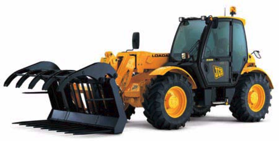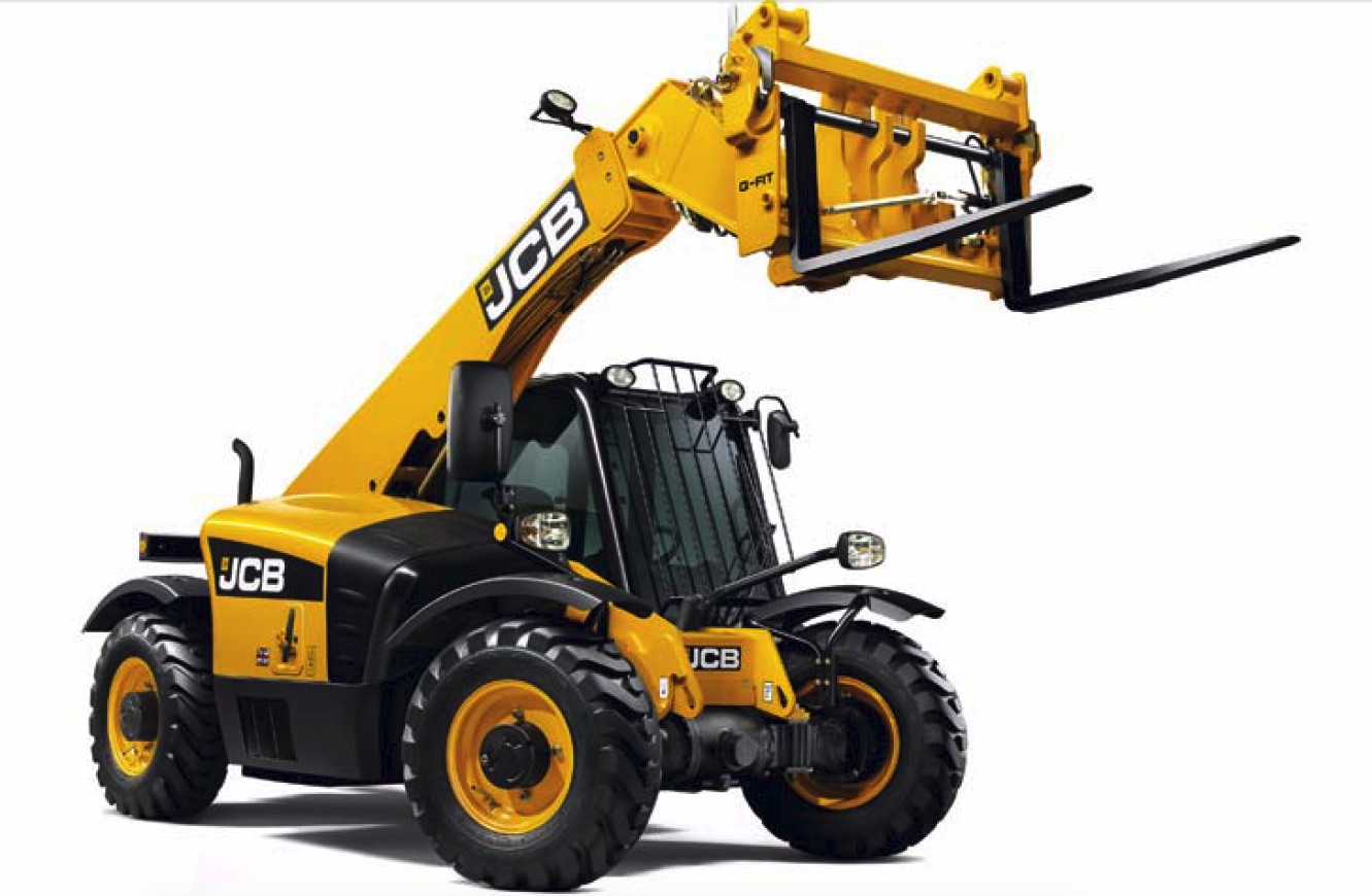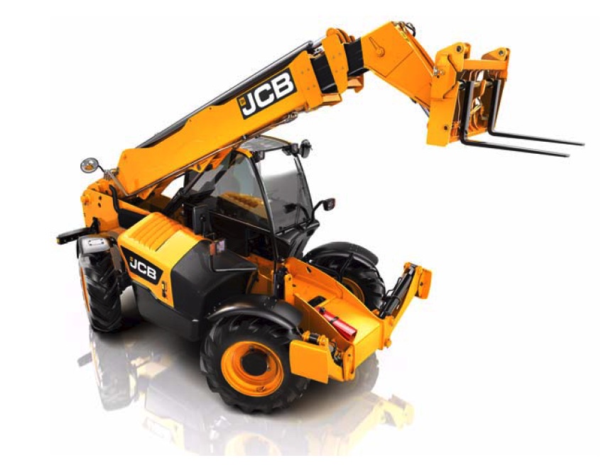
Complete workshop & service manual with electrical wiring diagrams for JCB Side Engine Loadalls (535-125 Hi Viz, 535-140 Hi Viz, 540-140, 540-170). It’s the same service manual used by dealers that guaranteed to be fully functional and intact without any missing page.
This JCB Side Engine Loadalls (535-125 Hi Viz, 535-140 Hi Viz, 540-140, 540-170) service & repair manual (including maintenance, overhaul, disassembling & assembling, adjustment, tune-up, operation, inspecting, diagnostic & troubleshooting…) is divided into different sections. Each section covers a specific component or system with detailed illustrations. A table of contents is placed at the beginning of each section. Pages are easily found by category, and each page is expandable for great detail. The printer-ready PDF documents work like a charm on all kinds of devices.
9813-0950 – JCB Side Engine Loadalls (535-125 Hi Viz, 535-140 Hi Viz, 540-140, 540-170) Service Manual.pdf
EXCERPT:
Service Manual
Side Engine Loadalls
Section 1 – General Information
Section 2 – Care and Safety
Section 3 – Routine Maintenance
Section B – Body and Framework
Section C – Electrics
Section E – Hydraulics
Section F – Transmission
Section G – Brakes
Section H – Steering
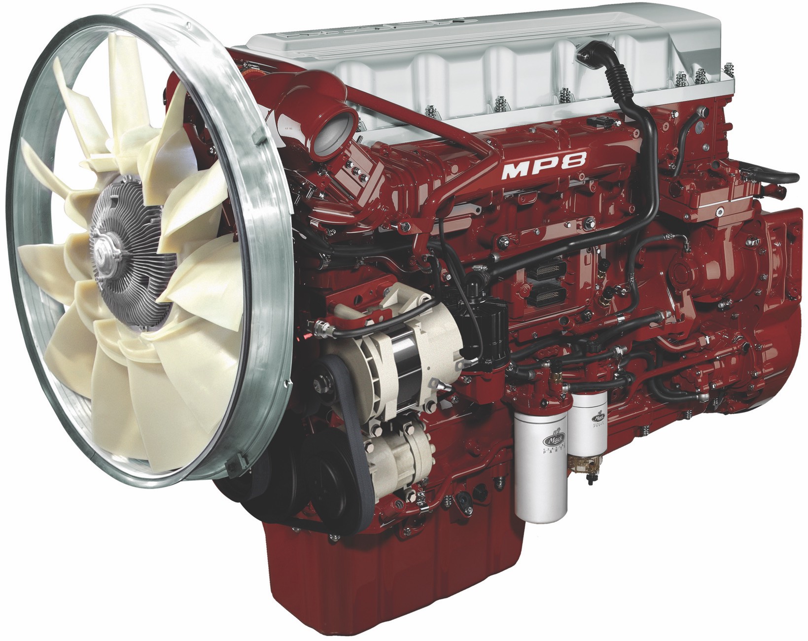
Section K – Engine
Section M – Electronic Data Systems
…
Converter Out Pressure and Oil Cooler Flow Rate
K Fig 18. ( T F5-43)
Note that the converter out pressure and oil cooler flow rate are affected by the torque converter relief valve operation. Before carrying out tests check the operation of the relief valve. K Converter Relief (Safety Valve) Pressure ( T F5-38)
1 Stop engine, connect a 0-20 bar (0-300 lbf/in2) pressure gauge and flowmeter into the converter out line as shown at C and K respectively.
Note: The flow meter may cause back pressure. If the torque converter relief valve is not by-passed, it may open and cause false readings.
2 Run the engine at 1000 rev/min with transmission in neutral. The pressure gauge indicates the Converter Out Pressure and the flowmeter indicates the Oil Cooler Flow Rate. Make sure that the readings are correct. K Specifications ( T F5-3)
A high pressure together with low flow could be caused by a blocked oil cooler. Low pressure could be caused by a faulty pump or internal leakage. 3 Repeat step 2, with engine running at 2000 rev/min note gauge readings. K Specifications ( T F5-3) 4 Stop engine, remove test gauges and refit hoses to original position. Remember to remove the torque converter relief valve by-pass assembly and refit the relief valve, (ball, spring and cover/plug).
…