Posted on

JCB JS370 Hydraulic Excavator Factory Service & Shop Manual


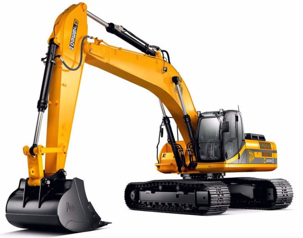
Pages from 9813-2250 – JCB JS370 Hydraulic Excavator Service Manual

MJCBJS370OPES.zip
Price: $29.99 USD

Complete workshop & service manual with electrical wiring diagrams for JCB JS370 Hydraulic Excavator. It’s the same service manual used by dealers that guaranteed to be fully functional and intact without any missing page.

This JCB JS370 Hydraulic Excavator service & repair manual (including maintenance, overhaul, disassembling & assembling, adjustment, tune-up, operation, inspecting, diagnostic & troubleshooting…) is divided into different sections. Each section covers a specific component or system with detailed illustrations. A table of contents is placed at the beginning of each section. Pages are easily found by category, and each page is expandable for great detail. The printer-ready PDF documents work like a charm on all kinds of devices.

FILELIST:
9813-2250 – JCB JS370 Hydraulic Excavator Service Manual.pdf
9803-3010 – JCB JS Machines Track Service Manual.pdf
9803-6450 – JCB AMS JS Machines Service Manual (Supplement).pdf

EXCERPT:
Service Manual – JS370
Section 1 – General Information
Section 2 – Care and Safety
Section 3 – Maintenance
Section B – Body & Framework
Section C – Electrics
Section E – Hydraulics
Section F – Transmission
Section J – Track and Running Gear
Section K – Engine

Track Gearbox
Dismantling and Assembly – JS370
Dismantling
Note: The numbers in the procedure refer to the exploded drawing. K Fig 57. ( T F-58).
1 Unscrew the 4 M12 x 120 socket head screws (22) of the hydraulic motor.
Fig 1.
2 Use an M12 eyebolt tightened on the motor base plate to remove the hydraulic motor (21).
Fig 2.
3 Remove the O-ring seal (18) from the hydraulic motor.
Fig 3.
4 Remove the motor adaptor flange (17).

Posted on

JCB JS360 Tier III Auto Hydraulic Excavator Factory Service & Shop Manual


Pages from 9803-9880 – JCB JS360 Tier III Auto Hydraulic Excavator Service Manual

MJCBJS360OPES.zip
Price: $29.99 USD

Complete workshop & service manual with electrical wiring diagrams for JCB JS360 Tier III Auto Hydraulic Excavator. It’s the same service manual used by dealers that guaranteed to be fully functional and intact without any missing page.

This JCB JS360 Tier III Auto Hydraulic Excavator service & repair manual (including maintenance, overhaul, disassembling & assembling, adjustment, tune-up, operation, inspecting, diagnostic & troubleshooting…) is divided into different sections. Each section covers a specific component or system with detailed illustrations. A table of contents is placed at the beginning of each section. Pages are easily found by category, and each page is expandable for great detail. The printer-ready PDF documents work like a charm on all kinds of devices.

FILELIST:
9803-9880 – JCB JS360 Tier III Auto Hydraulic Excavator Service Manual.pdf

EXCERPT:
Service Manual
JS360 Tier III Auto
Service Manual – JS360 Tier III Auto
Section 1 – General Information
Section 2 – Care and Safety
Section 3 – Routine Maintenance
Section B – Body & Framework
Section C – Electrics
Section E – Hydraulics
Section F – Transmission
Section J – Track and Running Gear
Section K – Engine

Section E – Hydraulics
Slew Motor Reduction Gear Assembly
Dismantling and Assembly
Inspection
Before assembling the gear box make sure that a thorough inspection of all the components is carried out. Remember that although a failed component may be easy to identify, the cause may be less easy to trace. It is also possible that a failed component may have caused damage to other areas of the gearbox.
Components that are subject to general wear and tear are the following5
Gears 2-2, 2-2, 2-7, 2-9, 2-11
Pinion shaft 2-21
Bearings 2-14, 2-18
Seals 2-15
1 Carefully clean all components using a suitable degreasing agent.
2 Carefully inspect all gears, bearings and shafts for signs of excessive wear or damage. If wear or damage is evident, components must be renewed.
3 In the case of damaged gears, for example a planetary gear, do not proceed to replace the individual gears but the entire assembly.

Posted on

JCB JS330 – Tier II & Tier III Auto Hydraulic Excavator Factory Service & Shop Manual


Pages from 9803-6540 – JCB JS330 – Tier II & Tier III Auto Hydraulic Excavator Service Manual

MJCBJS330OPES.zip
Price: $29.99 USD

Complete workshop & service manual with electrical wiring diagrams for JCB JS330 – Tier II & Tier III Auto Hydraulic Excavator. It’s the same service manual used by dealers that guaranteed to be fully functional and intact without any missing page.

This JCB JS330 – Tier II & Tier III Auto Hydraulic Excavator service & repair manual (including maintenance, overhaul, disassembling & assembling, adjustment, tune-up, operation, inspecting, diagnostic & troubleshooting…) is divided into different sections. Each section covers a specific component or system with detailed illustrations. A table of contents is placed at the beginning of each section. Pages are easily found by category, and each page is expandable for great detail. The printer-ready PDF documents work like a charm on all kinds of devices.

9803-6540 – JCB JS330 – Tier II & Tier III Auto Hydraulic Excavator Service Manual.pdf

EXCERPT:
Service Manual
JS330 – Tier II and Tier III Auto
Section 1 – General Information
Section 2 – Care and Safety
Section 3 – Routine Maintenance
Section B – Body & Framework
Section C – Electrics
Section E – Hydraulics
Section F – Transmission
Section J – Track and Running Gear
Section K – E

Assembly
Assembly is essentially a reverse of the dismantling procedure in the previous section.
Exchange or repair any parts not in accordance with instructions laid down in the Maintenance Standards.
Ensure that all parts are cleaned in the appropriate solvent and dried with compressed air.
Apply a thin film of hydraulic fluid to all sliding parts, bearings and other contact surfaces before assembly.
Replace all O-rings and seals, where appropriate cover with petroleum jelly before fitting.
1 Cylinder block assembly
Assemble spring seat 17, spring 16 and spring seat 15 to cylinder block 4 and fit snap ring 14.

Posted on

JCB JS290 Tier III Auto Hydraulic Excavator Factory Service & Shop Manual


Pages from 9803-9800 – JCB JS290 Tier III Auto Hydraulic Excavator Service Manual

MJCBJS290OPES.zip
Price: $29.99 USD

Complete workshop & service manual with electrical wiring diagrams for JCB JS290 Tier III Auto Hydraulic Excavator. It’s the same service manual used by dealers that guaranteed to be fully functional and intact without any missing page.

This JCB JS290 Tier III Auto Hydraulic Excavator service & repair manual (including maintenance, overhaul, disassembling & assembling, adjustment, tune-up, operation, inspecting, diagnostic & troubleshooting…) is divided into different sections. Each section covers a specific component or system with detailed illustrations. A table of contents is placed at the beginning of each section. Pages are easily found by category, and each page is expandable for great detail. The printer-ready PDF documents work like a charm on all kinds of devices.

9803-9800 – JCB JS290 Tier III Auto Hydraulic Excavator Service Manual.pdf

EXCERPT:
Service Manual
JS290 – Tier III Auto
Section 1 – General Information
Section 2 – Care and Safety
Section 3 – Routine Maintenance
Section B – Body & Framework
Section C – Electrics
Section E – Hydraulics
Section F – Transmission
Section J – Track and Running Gear
Section K – Engine

Cushion Control Off
Fig 6. Cushion Control Off
When the cushion switch is illuminated, the cushion solenoid is energised and pilot pressure is fed to port S on the cushion valve. The two inner left and right cushion spools are both pushed into the centre of the outer spool, so that the unrestricted galleries X and the cushion valve spools are open to allow the pilot outputs from the hand controller to pass through the valve unrestricted, to the main control valve. When the dipper hand controller is operated, pilot pressure from the lever to port A, moves the outer spool to the right and pilot pressure is fed to the dipper spool in the control valve, via port C. At the conclusion of the hand controller operation, the returning pilot oil, goes straight back to the lever, with no restriction.
There is no cushioning effect. Hot oil from port R returns to tank via the dipper hand controller, as it does in the warming circuit in the neutral position. K Fig 6. ( T E-117)

Posted on

JCB JS200W Hydraulic Excavator Factory Service & Shop Manual


Pages from 9803-9540 – JCB JS200W TIER III Hydraulic Excavator Service Manual

MJCBJS200WOPES.zip
Price: $29.99 USD

Complete workshop & service manual with electrical wiring diagrams for JCB JS200W Hydraulic Excavator. It’s the same service manual used by dealers that guaranteed to be fully functional and intact without any missing page.

This JCB JS200W Hydraulic Excavator service & repair manual (including maintenance, overhaul, disassembling & assembling, adjustment, tune-up, operation, inspecting, diagnostic & troubleshooting…) is divided into different sections. Each section covers a specific component or system with detailed illustrations. A table of contents is placed at the beginning of each section. Pages are easily found by category, and each page is expandable for great detail. The printer-ready PDF documents work like a charm on all kinds of devices.

FILELIST:
9803-6320 – JCB JS 200W Hydraulic Excavator Service Manual.pdf
9803-9540 – JCB JS200W TIER III Hydraulic Excavator Service Manual.pdf

EXCERPT:
Service Manual
JS200W TIER III
Service Manual – JS200W TIER III
Section 1 – General Information
Section 2 – Care and Safety
Section 3 – Maintenance
Section B – Body & Framework
Section C – Electrics
Section E – Hydraulics
Section F – Transmission
Section K – Engine

Horse Power Control Data Logging
Facility
When selected this function will log information on engine speed, pump milliamps and mode over a selectable period up to 15 mins and display the data as a graph.
– Press and hold the “SET” and “MODE” buttons on the EMS simultaneously for 20 seconds, until the “SERVICE OFF” message is displayed.
– Use the scroll arrows until the “HRSEPWR MON” message is displayed.
– Press the “ACK” button. You are now in the datalog function. This is confirmed by the message “MINUTES 1”.
– The time period for logging can now be adjusted from 1 to 15 minutes using the arrow keys.
– Press ‘ACK’ to start recording, the EMS will display “RUNNING” When complete the display will return to normal.
– The results of this test are then viewed through the Service Master, Data logging application using a laptop.