Posted on

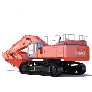
Hitachi ZAXIS 850/870 Hydraulic Excavator Factory Service & Shop Manual


Pages from W1JBE00 – Hitachi ZAXIS 850-3, 850LC-3, 870H-3, 870LCH-3 Hydraulic Excavator Workshop Manual


INSTANT DOWNLOAD


Complete workshop & service manual with electrical wiring diagrams for Hitachi ZAXIS 850-3, ZAXIS 850LC-3, ZAXIS 870H-3, ZAXIS 870LCH-3 Hydraulic Excavator. It’s the same service manual used by dealers that guaranteed to be fully functional and intact without any missing page.

This Hitachi ZAXIS 850-3, 850LC-3, 870H-3, 870LCH-3 Hydraulic Excavator service & repair manual (including maintenance, overhaul, disassembling & assembling, adjustment, tune-up, operation, inspecting, diagnostic & troubleshooting…) is divided into different sections. Each section covers a specific component or system with detailed illustrations. A table of contents is placed at the beginning of each section. Pages are easily found by category, and each page is expandable for great detail. The printer-ready PDF documents work like a charm on all kinds of devices.

FILE LIST:
TO1JBE00 – Hitachi ZAXIS 850-3, 850LC-3, 870H-3, 870LCH-3 Hydraulic Excavator Technical Manual (Operational Principle).pdf
TT1JBE00 – Hitachi ZAXIS 850-3, 850LC-3, 870H-3, 870LCH-3 Hydraulic Excavator Technical Manual (Troubleshooting).pdf
W1JBE00 – Hitachi ZAXIS 850-3, 850LC-3, 870H-3, 870LCH-3 Hydraulic Excavator Workshop Manual.pdf
EM1JB11 – Hitachi ZAXIS 850-3, 850LC-3, 870H-3, 870LCH-3 Hydraulic Excavator Operator’s Manual.pdf
EM1JB12 – Hitachi ZAXIS 850-3, 850LC-3, 870H-3, 870LCH-3 Hydraulic Excavator Operator’s Manual.pdf
EM17V21 – Hitachi ZAXIS 800, 850H Excavator Operator’s Manual.pdf
KO28200 – Hitachi ZAXIS 800, 850H Assembly Procedure Manual.pdf
KO28200 – Hitachi ZAXIS 800, 850H Excavator Assembly Procedure Manual.pdf
KO28900 – Hitachi ZAXIS 800, 850H Excavator Daily & Weekly Maintenance Check Sheets.pdf
T1JBE00 (attach to) – Hitachi ZAXIS 850-3 Electrical Circuit Diagram.pdf
T1JBE00 (attach to) – Hitachi ZAXIS 850-3 Hydraulic Circuit Diagram (Backhoe).pdf

EXCERPT:
SECTION 1 GENERAL INFORMATION
Group 1 Precautions for disassembling and Assembling
Group 2 Tightening Torque
Group 3 Painting
Group 4 Bleeding Air from Hydraulic Oil Tank
SECTION 2 UPPERSTRUCTURE
Group 1 Cab
Group 2 Counterweight
Group 3 Main Frame
Group 4 Pump Device
Group 5 Control Valve
Group 6 Swing Device
Group 7 Pilot Valve
Group 8 Pilot Shut-Off Solenoid Valve
Group 9 Solenoid Valve
Group 10 Signal Control Valve
Group 11 Shockless Valve
Group 12 Fan Motor
Group 13 Fan Valve
Group 14 Engine
SECTION 3 UNDERCARRIAGE
Group 1 Swing Bearing
Group 2 Travel Device
Group 3 Center Joint
Group 4 Track Adjuster
Group 5 Front Idler
Group 6 Upper and Lower Roller
Group 7 Track
SECTION 4 FRONT ATTACHMENT
Group 1 Front Attachment
Group 2 Cylinder

TECHNICAL MANUAL (Operational Principle)
SECTION 1 GENERAL
Group 1 Specification
Group 2 Component Layout
Group 3 Component Specifications
SECTION 2 SYSTEM
Group 1 Controller
Group 2 Control System
Group 3 ECM System
Group 4 Hydraulic System
Group 5 Electrical System
SECTION 3 COMPONENT OPERATION
Group 1 Pump Device
Group 2 Swing Device
Group 3 Control Valve
Group 4 Pilot Valve
Group 5 Travel Device
Group 6 Signal Control Valve
Group 7 Others (Upperstructure)
Group 8 Others (Undercarriage)
TECHNICAL MANUAL (Troubleshooting)
SECTION 4 OPERATIONAL PERFORMANCE TEST
Group 1 Introduction
Group 2 Standard
Group 3 Engine Test
Group 4 Excavator Test
Group 5 Component Test
Group 6 Adjustment
SECTION 5 TROUBLESHOOTING
Group 1 Diagnosing Procedure
Group 2 Monitor Unit
Group 3 Dr. ZX
Group 4 ICF
Group 5 Component Layout
Group 6 Troubleshooting A
Group 7 Troubleshooting B
Group 8 Electrical System Inspection

UPPERSTRUCTURE / Cab
REMOVE AND INSTALL CAB
Removal
CAUTION: Seat (1) weight: 40 kg (88 lb)
1. Remove bolts (2) (2 used). Remove the seat belt from bracket (4). : 16 mm
2. Remove socket bolts (3) (4 used) from seat (1).
Remove seat (1) from bracket (4). : 6 mm
3. Remove mat (6) from the cab (5) inside.


INSTANT DOWNLOAD


Posted on

Hitachi ZAXIS 800 Factory Service & Shop Manual


Pages from Hitachi ZAXIS 800 Service Manual

MHITZX800OPEK.zip
Price: $29.99 USD

Complete workshop & service manual with electrical wiring diagrams for Hitachi ZAXIS 800. It’s the same service manual used by dealers that guaranteed to be fully functional and intact without any missing page.

This Hitachi ZAXIS 800 service & repair manual (including maintenance, overhaul, disassembling & assembling, adjustment, tune-up, operation, inspecting, diagnostic & troubleshooting…) is divided into different sections. Each section covers a specific component or system with detailed illustrations. A table of contents is placed at the beginning of each section. Pages are easily found by category, and each page is expandable for great detail. The printer-ready PDF documents work like a charm on all kinds of devices.

Hitachi ZAXIS 800 Service Manual (191 MB)
Technical Manual (Operational Principle)
Part Position Display Tool
Technical Manual (Troubleshooting)
Circuit Diaglam & Harness
Workshop Manual

EXCERPT:
FRONT ATTACHMENT / Front Attachment
REMOVE AND INSTALL FRONT ATTACHMENT
CAUTION: Escaping fluid under pressure can penetrate the skin and eyes, causing serious injury. Avoid this hazard by relieving pressure before disconnecting hydraulic lines.
Hydraulic oil may be hot after operation and may spurt, possibly causing severe burns. Be sure to wait for oil to cool before starting any repair work.
The hydraulic oil tank cap may fly off due to remaining pressure if removed quickly.
Slowly loosen the cap to release any remaining pressure completely.
Preparation
1. Park the machine on a solid level surface.
Fully retract the arm and bucket cylinders and lower the front attachment onto the ground.
2. After stopping the engine, move the control levers several times to release any pressure remaining in the system. Rotate the hydraulic oil tank cap approx. 30° counterclockwise using a hexagon wrench to release the trapped air in the hydraulic oil tank. Refer to Bleeding Air from Hydraulic System on page W1-1-2. : 4 mm

Posted on

Hitachi ZAXIS 600/650/670 Excavator Factory Service & Shop Manual


Pages from W1J7E00 – Hitachi ZAXIS 650LC-3, 670LCH-3 Hydraulic Excavator Workshop Manual

MHITZX600ZX670OPEK.zip
Price: $29.99 USD

Complete workshop & service manual with electrical wiring diagrams for Hitachi ZAXIS 600, 650LC-3, 670LCH-3 Hydraulic Excavator. It’s the same service manual used by dealers that guaranteed to be fully functional and intact without any missing page.

This Hitachi ZAXIS 600, 650LC-3, 670LCH-3 Hydraulic Excavator service & repair manual (including maintenance, overhaul, disassembling & assembling, adjustment, tune-up, operation, inspecting, diagnostic & troubleshooting…) is divided into different sections. Each section covers a specific component or system with detailed illustrations. A table of contents is placed at the beginning of each section. Pages are easily found by category, and each page is expandable for great detail. The printer-ready PDF documents work like a charm on all kinds of devices.

FILELIST:
TO1J7E00 – Hitachi ZAXIS 650LC-3, 670LCH-3 Hydraulic Excavator Technical Manual (Operational Principle).pdf
TT1J7E00 – Hitachi ZAXIS 650LC-3, 670LCH-3 Hydraulic Excavator Technical Manual (Troubleshooting).pdf
W1J7E00 – Hitachi ZAXIS 650LC-3, 670LCH-3 Hydraulic Excavator Workshop Manual.pdf
Hitachi ZAXIS 600 Service Manual
EM1J711 – Hitachi ZAXIS 650LC-3, 670LCH-3 Hydraulic Excavator Operator’s Manual.pdf
EM1J712 – Hitachi ZAXIS 650LC-3, 670LCH-3 Hydraulic Excavator Operator’s Manual.pdf
PI7P12 – Hitachi ZAXIS 600, 600LC, 650H, 650LCH Excavator Parts Catalog.pdf

EXCERPT:
SECTION 1 GENERAL INFORMATION
Group 1 Precautions for disassembling and Assembling
Group 2 Tightening Torque
Group 3 Painting
Group 4 Bleeding Air from Hydraulic Oil Tank
SECTION 2 UPPERSTRUCTURE
Group 1 Cab
Group 2 Counterweight
Group 3 Main Frame
Group 4 Pump Device
Group 5 Control Valve
Group 6 Swing Device
Group 7 Pilot Valve
Group 8 Pilot Shut-Off Solenoid Valve
Group 9 Solenoid Valve
Group 10 Signal Control Valve
Group 11 Shockless Valve
Group 12 Fan Valve
Group 13 Fan Motor
Group 14 Engine
SECTION 3 UNDERCARRIAGE
Group 1 Swing Bearing
Group 2 Travel Device
Group 3 Center Joint
Group 4 Track Adjuster
Group 5 Front Idler
Group 6 Upper and Lower Roller
Group 7 Track
SECTION 4 FRONT ATTACHMENT
Group 1 Front Attachment
Group 2 Cylinder
TECHNICAL MANUAL (Operational Principle)
SECTION 1 GENERAL
Group 1 Specification
Group 2 Component Layout
Group 3 Component Specifications
SECTION 2 SYSTEM
Group 1 Controller
Group 2 Control System
Group 3 ECM System
Group 4 Hydraulic System
Group 5 Electrical System
SECTION 3 COMPONENT OPERATION
Group 1 Pump Device
Group 2 Swing Device
Group 3 Control Valve
Group 4 Pilot Valve
Group 5 Travel Device
Group 6 Signal Control Valve
Group 7 Others (Upperstructure)
Group 8 Others (Undercarriage)
TECHNICAL MANUAL (Troubleshooting)
SECTION 4 OPERATIONAL PERFORMANCE TEST
Group 1 Introduction
Group 2 Standard
Group 3 Engine Test
Group 4 Excavator Test
Group 5 Component Test
Group 6 Adjustment
SECTION 5 TROUBLESHOOTING
Group 1 Diagnosing Procedure
Group 2 Monitor Unit
Group 3 Dr. ZX
Group 4 ICF
Group 5 Component Layout
Group 6 Troubleshooting A
Group 7 Troubleshooting B
Group 8 Electrical System Inspection

UPPERSTRUCTURE / Engine
REMOVE AND INSTALL ENGINE
CAUTION: Release any pressure in the hydraulic oil tank before doing any work.
(Refer to BLEED AIR FROM HYDRAULIC OIL TANK on W1-4.) Remove the grounding wire from the battery.
Removal
1. Drain off coolant (60 L, 16 US gal.) from the radiator.
IMPORTANT: Insert the protection seat between muffler cover (1) and engine cover (2).
2. Open and lock engine cover (2). Remove lock pins (6) (3 used) and washers (5) (3 used) from stay (4) and cylinders (3) (2 used). Lay down engine cover (2) to the muffler cover (1) side.
CAUTION: Engine cover (2) weight: 59 kg (130 lb)
3. Remove bolts (8) (8 used) from hinges (9) (4 used). Attach a nylon sling to engine cover (2).
Hoist and remove engine cover (2). : 17 mm
CAUTION: Muffler cover (1) weight: 35 kg (77 lb)
4. Remove bolts (10) (9 used) from muffler cover (1).
Attach a nylon sling to muffler cover (1). Hoist and remove muffler cover (1). : 19 mm

Posted on

Hitachi ZAXIS 450-3, 450LC-3, 470H-3, 470LCH-3, 500LC-3, 520LCH-3 Excavator Factory Service & Shop Manual


Pages from W1J1E00 – Hitachi ZAXIS 450-3, 450LC-3, 470H-3, 470LCH-3, 500LC-3, 520LCH-3 Hydraulic Excavator Workshop Manual

MHITZX450ZX520OPEK.zip
Price: $29.99 USD

Complete workshop & service manual with electrical wiring diagrams for Hitachi ZAXIS 450-3, 450LC-3, 470H-3, 470LCH-3, 500LC-3, 520LCH-3 Hydraulic Excavator. It’s the same service manual used by dealers that guaranteed to be fully functional and intact without any missing page.

This Hitachi ZAXIS 450-3, 450LC-3, 470H-3, 470LCH-3, 500LC-3, 520LCH-3 Hydraulic Excavator service & repair manual (including maintenance, overhaul, disassembling & assembling, adjustment, tune-up, operation, inspecting, diagnostic & troubleshooting…) is divided into different sections. Each section covers a specific component or system with detailed illustrations. A table of contents is placed at the beginning of each section. Pages are easily found by category, and each page is expandable for great detail. The printer-ready PDF documents work like a charm on all kinds of devices.

FILELIST:
TO1J1E00 – Hitachi ZAXIS 450-3, 450LC-3, 470H-3, 470LCH-3, 500LC-3, 520LCH-3 Hydraulic Excavator Technical Manual (Operational Principle).pdf
TT1J1E00 – Hitachi ZAXIS 450-3, 450LC-3, 470H-3, 470LCH-3, 500LC-3, 520LCH-3 Hydraulic Excavator Technical Manual (Troubleshooting).pdf
W1J1E00 – Hitachi ZAXIS 450-3, 450LC-3, 470H-3, 470LCH-3, 500LC-3, 520LCH-3 Hydraulic Excavator Workshop Manual.pdf
TT1J1E00 (attach to) – Hitachi ZAXIS 450-3, 500LC-3, 520LCH-3, 650LC-3, 850-3 Electrical Wiring Diagrams.pdf
Electrical Wiring Diagrams
Hitachi ZAXIS 450-3 Class, 500-3 Class (EU) Training Materials
Hitachi ZAXIS 450-3, 500-3 (Standard) Training Materials
EM1J111 – Hitachi ZAXIS 450-3, 450LC-3, 450H-3, 450LCH-3, 470LCH-3, 500LC-3, 520LCH-3 Hydraulic Excavator Operator’s Manual.pdf
EM1J112 – Hitachi ZAXIS 450-3, 450LC-3, 470H-3, 470LCH-3, 500LC-3, 520LCH-3 Hydraulic Excavator Operator’s Manual.pdf
EM1JK-1-1 – Hitachi ZAXIS 400R-3, 400LCH-3 Hydraulic Excavator Operator’s Manual.pdf
EM16J31 – Hitachi ZAXIS 450, 450H, 450LC, 450LCH, 460LCH Excavator Operator’s Manual.pdf
EM16R21 – Hitachi ZAXIS 500LC, 500LCH Excavator Operator’s Manual.pdf
EPM1J1USL12 – Hitachi ZAXIS 450LC-3, 470LCH-3 Super Long Front Attachment (Type 20) Hydraulic Excavator Operator’s Manual_Parts Catalog.pdf
P1JKOP11 – Hitachi ZAXIS 400R-3, 400LCH-3 Hydraulic Excavator Parts Catalog.pdf
PI6J13 – Hitachi ZAXIS 450, 450LC, 450H, 450LCH, 460LCH, 480MT, 480MTH Excavator Operator’s Manual_Parts Catalog.pdf
PI6JE12 – Hitachi ZAXIS 450, 450LC, 470H-3, 470LCH-3, 500LC-3, 520LCH-3 Equipment Component Parts Catalog.pdf
PSEN004 – Hitachi ZAXIS 450, 450LC, 470H, 470LCH Sales Manual.pdf
PSEN021 – Hitachi ZAXIS 400LCH, 400R Sales Manual.pdf

EXCERPT:
UNDERCARRIAGE / Swing Bearing
REMOVE AND INSTALL SWING BEARING
Before removing and installing the swing bearing, the upperstructure must be removed first. For removal and installation of the upperstructure, refer to “Remove and Install Frame”, “Remove and Install Front Attachment” and “Remove and Install Counterweight” sections.
In this section, the procedure starts on the premise that the upperstructure has already been removed.
Removal
1. Put the matching marks on inner race (3) of swing bearing (1) and track frame (2).
2. Remove all grease pipes from swing bearing (1). : 17 mm
3. Remove bolts (4) (40 used) from swing bearing (1). : 41 mm
CAUTION: Swing bearing (1) weight: 642 kg (1420 Ib)
4. Install lifting tool (ST 9050) to swing bearing (1). Hoist and remove swing bearing (1) from track frame (2).

Posted on

Hitachi ZAXIS 450 Factory Service & Shop Manual


Pages from W16JE00 – Hitachi ZAXIS 450 Workshop Manual

MHITZX450OPEK.zip
Price: $29.99 USD

Complete workshop & service manual with electrical wiring diagrams for Hitachi ZAXIS 450 Backhoe/Loading Shovel/Excavator. It’s the same service manual used by dealers that guaranteed to be fully functional and intact without any missing page.

This Hitachi ZAXIS 450 Backhoe/Loading Shovel/Excavator service & repair manual (including maintenance, overhaul, disassembling & assembling, adjustment, tune-up, operation, inspecting, diagnostic & troubleshooting…) is divided into different sections. Each section covers a specific component or system with detailed illustrations. A table of contents is placed at the beginning of each section. Pages are easily found by category, and each page is expandable for great detail. The printer-ready PDF documents work like a charm on all kinds of devices.

FILELIST:
TO16JE00 – Hitachi ZAXIS 450 Technical Manual (Operational Principle)
TT16JE00 – Hitachi ZAXIS 450 Technical Manual (Troubleshooting)
W16JE00 – Hitachi ZAXIS 450 Workshop Manual
Hitachi ZAXIS 450, 450LC, 450H, 450LCH Backhoe_Loading Shovel_Excavator Technical Manual (Troubleshooting).pdf
Hitachi ZAXIS 450, 450LC, 450H, 450LCH Backhoe/Loading Shovel/Excavator Technical Manual (Operational Principle).pdf
Electrical Wiring Diagrams

EXCERPT:
UPPERSTRUCTURE / Cab
Removal of Right-hand Cab Glass
1. Insert bamboo spatula into position A in mounting rubber to pry the mounting rubber apart along all periphery.
NOTE: It is easier to remove glass with air gap between cab and mounting rubber as performed by step 1.
IMPORTANT: Be sure to perform the work by two persons or more.
2. Tap glass from the side in cab by palm of the hand to remove it.
Removal of Rear Side Cab Glass
1. Remove stopper (groove rubber) with a screwdriver.
2. Insert a bamboo spatula into position A in mounting rubber to pry the mounting rubber apart along all periphery.
IMPORTANT: Be sure to perform the work by two persons or more.
3. Tap glass from the side in cab by palm of the hand to remove it.