Posted on

John Deere 17D Excavator Operation & Test Manual (TM10258)


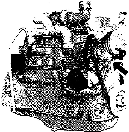
Engine Oil Pressure Test from MJODTM10258OPES


Download Link

INSTANT DOWNLOAD (add to cart)

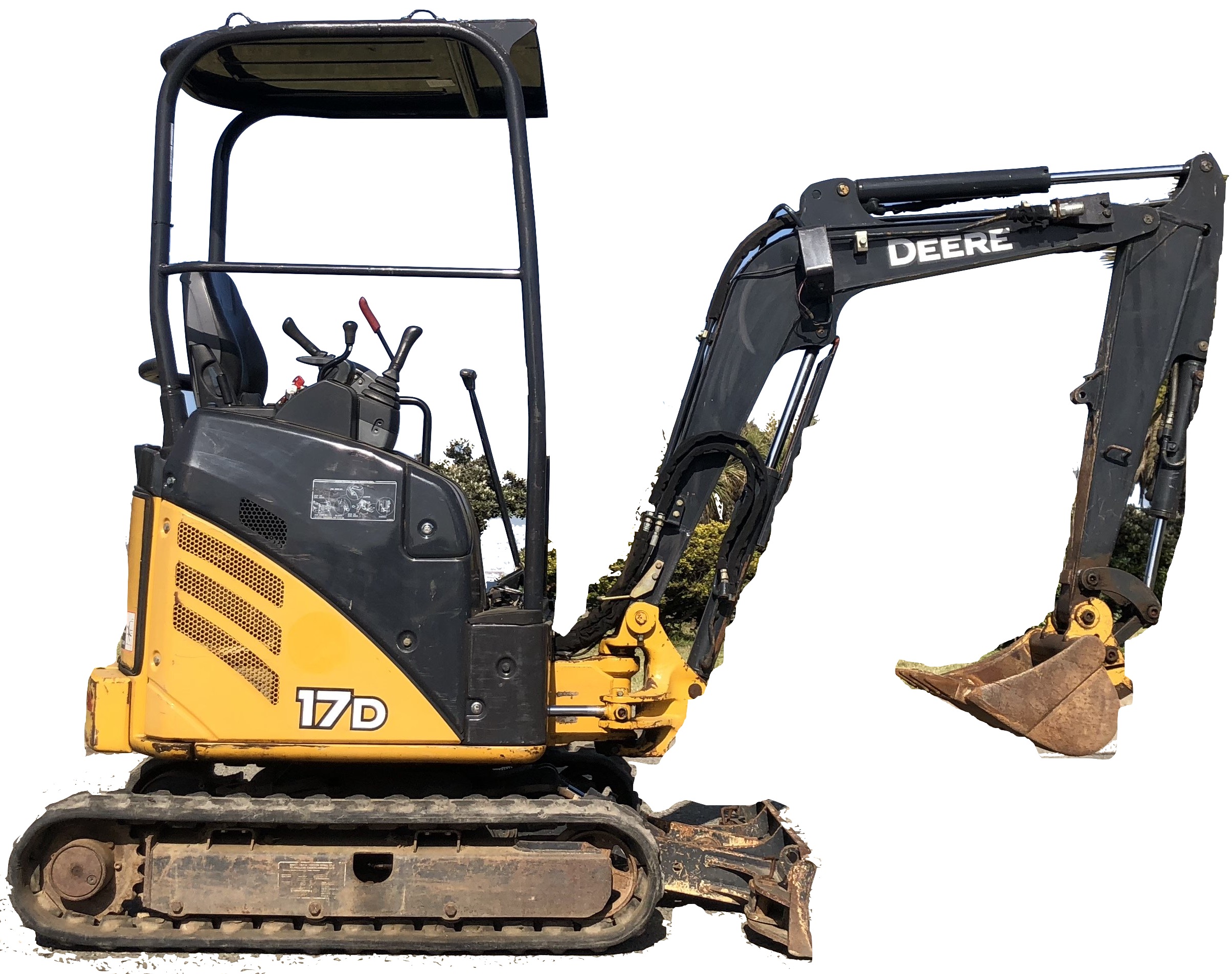
Complete technical Operation & Test Manual with electrical wiring diagrams for John Deere 17D Excavator. It’s the same service manual used by dealers that guaranteed to be fully functional and intact without any missing page.

This John Deere 17D Excavator Operation & Test Manual (including maintenance, overhaul, disassembling & assembling, adjustment, tune-up, operation, inspecting, diagnostic & troubleshooting…) is divided into different sections. Each section covers a specific component or system with detailed illustrations. A table of contents is placed at the beginning of each section. Pages are easily found by category, and each page is expandable for great detail. The printer-ready PDF documents work like a charm on all kinds of devices.

TM10258 – John Deere 17D Excavator Operation & Test Manual.pdf; 4bookmarked, Searchable, Printable, high quality PDF

EXCERPT:
Table of Contents (exploded views)
TM10258 – John Deere 17D Excavator Operation & Test Manual
├── Foreword.pdf
├── 9000 – General Information
│   └── 01 – Safety
│   ├── Add and Operate Attachments Safely.pdf
│   ├── Add Operator’s Station Guarding for Special Uses.pdf
│   ├── Avoid Backover Accidents.pdf
│   ├── Avoid High-Pressure Fluids.pdf
│   ├── Avoid High-Pressure Oils .pdf
│   ├── Avoid Machine Tip Over.pdf
│   ├── Avoid Unauthorized Machine Modifications.pdf
│   ├── Avoid Work Site Hazards .pdf
│   ├── Beware of Exhaust Fumes.pdf
│   ├── Dispose of Waste Properly .pdf
│   ├── Drive Metal Pins Safely.pdf
│   ├── Follow Safety Instructions.pdf
│   ├── Handle Chemical Products Safely .pdf
│   ├── Inspect Machine.pdf
│   ├── Keep Riders Off Machine.pdf
│   ├── Make Welding Repairs Safely.pdf
│   ├── Operate Only If Qualified.pdf
│   ├── Park and Prepare for Service Safely.pdf
│   ├── Prepare for Emergencies.pdf
│   ├── Prevent Battery Explosions.pdf
│   ├── Prevent Fires.pdf
│   ├── Prevent Unintended Machine Movement.pdf
│   ├── Recognize Safety Information.pdf
│   ├── Remove Paint Before Welding or Heating.pdf
│   ├── Service Cooling System Safely.pdf
│   ├── Start Only From Operator’s Seat .pdf
│   ├── Stay Clear of Moving Parts.pdf
│   ├── Use and Maintain Seat Belt.pdf
│   ├── Use Special Care When Lifting Objects.pdf
│   ├── Use Steps and Handholds Correctly .pdf
│   └── Wear Protective Equipment.pdf
├── 9005 – Operational Checkout Procedure
│   └── 10 – Operational Checkout Procedure
│   └── Operational Checkout.pdf
├── 9010 – Engine
│   ├── Air Intake System Leakage Test .pdf
│   ├── Bleed Fuel System.pdf
│   ├── Cooling System Pressure Test.pdf
│   ├── Diagnose Engine Malfunctions.pdf
│   ├── Engine Component Location.pdf
│   ├── Engine Compression Pressure Test.pdf
│   ├── Engine Cooling System Operation.pdf
│   ├── Engine Fuel System Operation.pdf
│   ├── Engine Lubrication System Operation .pdf
│   ├── Engine Oil Pressure Test .pdf
│   ├── Engine Speed Check.pdf
│   ├── Engine Speed Control Lever and Cable Adjustment.pdf
│   ├── Engine Thermostat Test.pdf
│   ├── Engine Valve Lash (Clearance) Check and Adjustment .pdf
│   ├── Fan Belt Tension Adjustment.pdf
│   ├── Fuel Injection Nozzle Check.pdf
│   ├── Fuel Transfer Pump Pressure Test.pdf
│   ├── Head Gasket Failure Check.pdf
│   ├── Injection Pump Timing Check and Adjustment .pdf
│   ├── JT05801 Clamp-On Electronic Tachometer Installation.pdf
│   └── Radiator Cap Test .pdf
├── 9015 – Electrical System
│   ├── 05 – System Information
│   │   ├── Component Identification Table .pdf
│   │   ├── Electrical Diagram Information .pdf
│   │   └── Fuse (Blade-Type) Color Codes .pdf
│   ├── 10 – System Diagrams
│   │   ├── Battery and Ground Cables (W6 and W7) Component Location .pdf
│   │   ├── Boom Work Light Harness (W3) Component Location .pdf
│   │   ├── Boom Work Light Harness (W3) Wiring Diagram.pdf
│   │   ├── Engine Harness (W2) Component Location .pdf
│   │   ├── Engine Harness (W2) Wiring Diagram .pdf
│   │   ├── Fuse Specifications .pdf
│   │   ├── Platform Harness (W1) Component Location .pdf
│   │   ├── Platform Harness (W1) Wiring Diagram.pdf
│   │   ├── System Functional Schematic and Section Legend .pdf
│   │   └── System Functional Schematic, Wiring Diagrams, and Component Locations Master Legend .pdf
│   ├── 15 – Sub-System Diagnostics
│   │   ├── Fuel Shutoff Circuit Theory of Operation.pdf
│   │   ├── Monitor Panel Circuit Theory of Operation .pdf
│   │   ├── Pilot Control Shutoff Circuit Theory of Operation .pdf
│   │   ├── Start and Charge Circuits Theory of Operation.pdf
│   │   └── Travel Speed Control and Travel Alarm Circuit Theory of Operation.pdf
│   └── 20 – References
│   ├── Alternator and Starting Motors.pdf
│   ├── Alternator Test .pdf
│   ├── Electrical Component Specifications.pdf
│   ├── Install WEATHER PACK 342204242 Contact.pdf
│   ├── Remove Connector Body from Blade Terminals .pdf
│   ├── Replace DEUTSCH 342204242 Rectangular or Triangular Connectors .pdf
│   └── Replace WEATHER PACK 342204242 Connector .pdf
├── 9020 – Power Train
│   ├── Diagnose Undercarriage Components Malfunctions.pdf
│   ├── Measure Swing Bearing Wear.pdf
│   ├── Track Adjuster and Recoil Spring Operation.pdf
│   └── Travel Gearcase Operation.pdf
├── 9025 – Hydraulic System
│   ├── 05 – Theory of Operation
│   │   ├── Arm Regenerative Valve Operation.pdf
│   │   ├── Auxiliary Selector Valve Operation.pdf
│   │   ├── Blade, Boom Swing, and Auxiliary Pilot Controller Operation.pdf
│   │   ├── Blade Circuit Operation .pdf
│   │   ├── Bucket, Boom, and Boom Swing Anticavitation Valve Operation.pdf
│   │   ├── Circuit Relief Valve Operation .pdf
│   │   ├── Control Valve Operation.pdf
│   │   ├── Flow Combiner Valve Operation.pdf
│   │   ├── Hydraulic Cylinder Operation .pdf
│   │   ├── Hydraulic Oil Return Filter Operation.pdf
│   │   ├── Hydraulic Pump 1 and 2 Operation.pdf
│   │   ├── Hydraulic Pump 3 Operation.pdf
│   │   ├── Hydraulic Pump Regulator Operation.pdf
│   │   ├── Hydraulic System Circuit Symbols.pdf
│   │   ├── Hydraulic System Diagram.pdf
│   │   ├── Hydraulic System Schematics.pdf
│   │   ├── Pilot Controller Operation .pdf
│   │   ├── Pilot Filter Bypass Operation.pdf
│   │   ├── Pilot.pdf
│   │   ├── Pilot Pump Operation.pdf
│   │   ├── Pilot System Diagram .pdf
│   │   ├── Rotary Manifold Operation.pdf
│   │   ├── Swing Motor Anticavitation Valve Operation.pdf
│   │   ├── Swing Motor Crossover Relief Valve Operation .pdf
│   │   ├── Swing Motor Operation .pdf
│   │   ├── Swing Motor Park Brake Release Circuit Operation.pdf
│   │   ├── System Relief Valve Operation.pdf
│   │   ├── Travel Motor Counterbalance Valve Operation .pdf
│   │   ├── Travel Motor Operation.pdf
│   │   ├── Travel Motor Park Brake Operation .pdf
│   │   ├── Travel Motor Speed Change Valve Operation.pdf
│   │   └── Travel Pilot Controller Operation .pdf
│   ├── 15 – Diagnostic Informtion
│   │   ├── Blade Hydraulic System Line Identification .pdf
│   │   ├── Diagnose Dig Circuit Malfunctions .pdf
│   │   ├── Diagnose Hydraulic System Malfunctions .pdf
│   │   ├── Diagnose Pilot Circuit Malfunctions.pdf
│   │   ├── Diagnose Swing Circuit Malfunctions.pdf
│   │   ├── Diagnose Travel System Malfunctions.pdf
│   │   ├── Diagnostic Procedure .pdf
│   │   ├── Main Hydraulic Pilot System Line Identification.pdf
│   │   ├── Main Hydraulic Working System Line Identification .pdf
│   │   ├── Major Component Location.pdf
│   │   ├── Pilot Controller to Pattern Conversion Valve Line Connection.pdf
│   │   └── Travel Hydraulic System Line Identification .pdf
│   ├── 20 – Adjustments
│   └── 25 – Tests
│   ├── Circuit Relief Valve Test and Adjustment.pdf
│   ├── Control Valve Spool Pilot Actuating Pressure Test .pdf
│   ├── Cylinder Drift Test342200224Boom, Arm, Bucket, and Blade.pdf
│   ├── Hydraulic Oil Cleanup Procedure Using Portable Filter Caddy.pdf
│   ├── Hydraulic Pump 1 and 2 Flow Test .pdf
│   ├── Hydraulic Pump 3 Flow Test.pdf
│   ├── Hydraulic Pumps 1, 2, and 3 System Relief Valve Test and Adjustment.pdf
│   ├── Hydraulic Pumps 1 and 2 Regulator Test and Adjustment342200224Engine Pulldown.pdf
│   ├── Hydraulic System Warmup Procedure.pdf
│   ├── JT02156A Digital Pressure _ Temperature Analyzer Installation.pdf
│   ├── JT05800 Digital Thermometer Installation.pdf
│   ├── Pilot Pressure Regulating Valve Test and Adjustment.pdf
│   ├── Swing Motor Crossover Relief Valve Test and Adjustment.pdf
│   ├── Swing Motor Leakage Test.pdf
│   └── Travel Motor Leakage Test.pdf

Posted on

John Deere 744K 4WD Loader with Engine 6090HDW12 (iT4) Repair Manual (TM11744)


Orbital Steering Valve Remove and Install


INSTANT DOWNLOAD


John Deere 744K 4WD Loader with Engine 6090HDW12 (iT4) Repair Manual (TM11744)
Complete technical Repair Manual with electrical wiring diagrams for John Deere 744K 4WD Loader with Engine 6090HDW12 (iT4). It’s the same service manual used by dealers that guaranteed to be fully functional and intact without any missing page.

This John Deere 744K 4WD Loader with Engine 6090HDW12 (iT4) (S.N. 630720-664577) Repair Manual (including maintenance, overhaul, disassembling & assembling, adjustment, tune-up, operation, inspecting, diagnostic & troubleshooting…) is divided into different sections. Each section covers a specific component or system with detailed illustrations. A table of contents is placed at the beginning of each section. Pages are easily found by category, and each page is expandable for great detail. The printer-ready PDF documents work like a charm on all kinds of devices.

TM11744 – John Deere 744K 4WD Loader with Engine 6090HDW12 (iT4) (S.N. 630720-664577) Repair Manual.pdf; 475 pages, bookmarked, Searchable, Printable, high quality PDF)

EXCERPT:
Table of Contents (exploded views)
├── Foreword.pdf
└── Manual Identification342200224READ THIS FIRST!.pdf
├── 00 – General Information
│   ├── 01 – Safety
│   │   ├── Add and Operate Attachments Safely.pdf
│   │   ├── Add Cab Guarding For Special Uses.pdf
│   │   ├── Avoid Backover Accidents.pdf
│   │   ├── Avoid High-Pressure Fluids.pdf
│   │   ├── Avoid High-Pressure Oils.pdf
│   │   ├── Avoid Machine Tip Over.pdf
│   │   ├── Avoid Unauthorized Machine Modifications.pdf
│   │   ├── Avoid Work Site Hazards.pdf
│   │   ├── Clean Debris from Machine.pdf
│   │   ├── Clean Exhaust Filter Safely.pdf
│   │   ├── Decommissioning Proper Recycling and Disposal of Fluids and Components.pdf
│   │   ├── Drive Metal Pins Safely.pdf
│   │   ├── Exhaust Filter Ash Handling and Disposal.pdf
│   │   ├── Follow Safety Instructions.pdf
│   │   ├── Handle Chemical Products Safely.pdf
│   │   ├── Inspect and Maintain ROPS.pdf
│   │   ├── Inspect Machine.pdf
│   │   ├── Keep Riders Off Machine.pdf
│   │   ├── Make Welding Repairs Safely.pdf
│   │   ├── Operate Only If Qualified.pdf
│   │   ├── Operating on Slopes.pdf
│   │   ├── Operating or Traveling On Public Roads.pdf
│   │   ├── Park And Prepare For Service Safely.pdf
│   │   ├── Prepare for Emergencies.pdf
│   │   ├── Prevent Battery Explosions.pdf
│   │   ├── Prevent Fires.pdf
│   │   ├── Prevent Unintended Machine Movement.pdf
│   │   ├── Recognize Safety Information.pdf
│   │   ├── Remove Paint Before Welding or Heating.pdf
│   │   ├── Service Cooling System Safely.pdf
│   │   ├── Service Tires Safely.pdf
│   │   ├── Start Only From Operator’s Seat.pdf
│   │   ├── Stay Clear of Moving Parts.pdf
│   │   ├── Use and Maintain Seat Belt.pdf
│   │   ├── Use Special Care When Operating Loader.pdf
│   │   ├── Use Steps and Handholds Correctly.pdf
│   │   ├── Wear Protective Equipment.pdf
│   │   └── Work In Ventilated Area.pdf
│   └── 03 – Torque Values
│   ├── Additional Metric Cap Screw Torque Values.pdf
│   ├── Inch Series Four Bolt Flange Fitting For High Pressure Service Recommendations.pdf
│   ├── Metric 24302260 O-Ring Seal DIN 20078 Service Recommendations.pdf
│   ├── Metric Bolt and Cap Screw Torque Values.pdf
│   ├── O-Ring Face Seal Fittings With Metric Hex Nut And Stud End For High Pressure Service Recommendations.pdf
│   ├── O-Ring Face Seal Fittings With Metric Hex Nut And Stud End For Standard Pressure Service Recommendations.pdf
│   ├── O-Ring Face Seal Fittings With SAE Inch Hex Nut And Stud End For High Pressure Service Recommendations.pdf
│   ├── Service Recommendations for 37302260 Flare and 30302260 Cone Seat Connectors.pdf
│   ├── Service Recommendations For Flared Connections342200224Straight or Tapered Threads.pdf
│   ├── Service Recommendations For Flat Face O-Ring Seal Fittings.pdf
│   ├── Service Recommendations For Inch Series Four Bolt Flange Fittings.pdf
│   ├── Service Recommendations for Metric Series Four Bolt Flange Fitting.pdf
│   ├── Service Recommendations For Non-Restricted Banjo (Adjustable) Fittings.pdf
│   ├── Service Recommendations for O-Ring Boss Fittings.pdf
│   ├── Service Recommendations For O-Ring Boss Fittings With Shoulder.pdf
│   └── Unified Inch Bolt and Cap Screw Torque Values.pdf
├── 01 – Tracks
│   ├── Tire Remove and Install.pdf
│   └── Wheel Remove and Install.pdf
├── 02 – Axles and Suspension Systems
│   ├── Axle Circulation Pump Remove and Install.pdf
│   ├── Axle Oscillating Supports Disassemble and Assemble.pdf
│   ├── Differential Lock Solenoid Valve Remove and Install.pdf
│   ├── Front Axle and Differential Remove and Install.pdf
│   ├── Rear Axle and Differential Remove and Install.pdf
│   ├── TeamMate342204242 II Axles.pdf
│   └── Universal Joint and Drive Shaft Remove and Install.pdf
├── 03 – Transmission
│   ├── Clutch Packs Remove and Install.pdf
│   ├── High Range Forward Clutch (K4) and Third Speed Clutch (K3) Bearing Preload Adjustment.pdf
│   ├── Low Range Forward Clutch (KV) and First Speed Clutch (K1) Bearing Preload Adjustment.pdf
│   ├── Reverse Clutch (KR) and Second Speed Clutch (K2) Bearing Preload Adjustment.pdf
│   ├── Torque Converter Housing Disassemble and Assemble.pdf
│   ├── Torque Converter Input Shaft Remove and Install.pdf
│   ├── Transmission Drive Three Disassemble and Assemble.pdf
│   ├── Transmission Drive Two Disassemble and Assemble.pdf
│   ├── Transmission Hydraulic Control Valve Disassemble and Assemble.pdf
│   ├── Transmission Hydraulic Control Valve Remove and Install.pdf
│   ├── Transmission Input Shaft Disassemble and Assemble.pdf
│   ├── Transmission Input Shaft Remove and Install.pdf
│   ├── Transmission Pump Disassemble and Assemble.pdf
│   ├── Transmission Pump Remove and Install.pdf
│   ├── Transmission Remove and Install.pdf
│   ├── Transmission Speed Sensors Remove and Install.pdf
│   └── Transmission Suction Screen Remove and Install.pdf
├── 04 – Engine
│   ├── Crankshaft Dampener Remove and Install.pdf
│   ├── Engine Remove and Install.pdf
│   └── PowerTech342204242 PSX 9.0L (6090) John Deere Engine.pdf
├── 05 – Engine Auxiliary Systems
│   ├── Air Cleaner Remove and Install.pdf
│   ├── Axle Oil Cooler Remove and Install.pdf
│   ├── Charge Air Cooler Remove and Install.pdf
│   ├── Cooling Package Plenum Remove and Install.pdf
│   ├── Diesel Particulate Filter (DPF) Remove and Install.pdf
│   ├── Engine Coolant Heater Remove and Install342200224If Equipped.pdf
│   ├── Exhaust Bellows Alignment Procedure.pdf
│   ├── Exhaust Filter Remove and Install.pdf
│   ├── Exhaust Tube Remove and Install.pdf
│   ├── Fast Fill Fuel System Disassemble and Assemble342200224If Equipped.pdf
│   ├── Fuel Cooler Remove and Install.pdf
│   ├── Fuel Tank Remove and Install.pdf
│   ├── Hydraulic Oil Cooler Remove and Install.pdf
│   ├── JDG11335 Bellows Alignment Fixture.pdf
│   ├── Precleaner Remove and Install.pdf
│   ├── Primary Fuel Filter (Water Separator) Remove and Install.pdf
│   ├── Radiator Remove and Install.pdf
│   ├── Service Filter Cleaning.pdf
│   ├── Start Aid Nozzle Remove and Install342200224If Equipped.pdf
│   ├── Start Aid Solenoid Remove and Install342200224If Equipped.pdf
│   └── Transmission Oil Cooler Remove and Install.pdf
├── 07 – Dampener Drive
│   └── Output Dampener Remove and Install.pdf
├── 09 – Steering System
│   ├── Joystick Steering Valve Disassemble and Assemble342200224If Equipped.pdf
│   ├── Joystick Steering Valve Remove and Install342200224If Equipped.pdf
│   ├── Loader Start-Up Procedure (Steering Cylinder).pdf
│   ├── NeverGrease342204242 Pin Joints.pdf
│   ├── Orbital Steering Valve Remove and Install.pdf
│   ├── Secondary Steering Pump Remove and Install342200224If Equipped.pdf
│   ├── Secondary Steering Valve Remove and Install342200224If Equipped.pdf
│   ├── Steering Column Disassemble and Assemble.pdf
│   ├── Steering Column Remove and Install.pdf
│   ├── Steering Cylinder Bushings Remove and Install.pdf
│   └── Steering Cylinders Remove and Install.pdf
├── 10 – Service Brakes
│   ├── Service Brake Accumulator Remove and Install.pdf
│   ├── Service Brake Assembly Remove and Install.pdf
│   ├── Service Brake Pedal and Linkage Disassemble and Assemble.pdf
│   └── Service Brake Valve Remove and Install.pdf
├── 11 – Park Brake
│   ├── Park Brake Disassemble and Assemble.pdf
│   ├── Park Brake Release Solenoid Valve Remove and Install.pdf
│   └── Park Brake Remove and Install.pdf
├── 17 – Frames, Chassis, or Supporting Structure
│   ├── Counterweights Remove and Install.pdf
│   ├── Engine and Loader Frame Separate.pdf
│   ├── Front Axle Guard Remove and Install.pdf
│   ├── Fuel Tank Guard Remove and Install.pdf
│   ├── Lower Pivot Bearing and Seals Remove and Install.pdf
│   ├── Transmission Bottom Guard Remove and Install.pdf
│   ├── Upper Pivot Bearing and Seals Remove and Install.pdf
│   └── Welding Major Structure.pdf
├── 18 – Operator’s Station
│   ├── Air Conditioner High-Low Pressure Switch Remove and Install.pdf
│   ├── Air Conditioner System Cleaning Procedures.pdf
│   ├── Air Conditioner System Flush.pdf
│   ├── Air Conditioner System Purge.pdf
│   ├── Blower Motor Assembly Remove and Install.pdf
│   ├── Cab Door Hold-Open Latch Pin Adjust.pdf
│   ├── Cab Door Hold-Open Release Adjust.pdf
│   ├── Cab Remove and Install.pdf
│   ├── Compressor Remove and Install.pdf
│   ├── Condenser Remove and Install.pdf
│   ├── Expansion Valve Remove and Install.pdf
│   ├── Freeze Control Switch Bench Test.pdf
│   ├── Freeze Control Switch Remove and Install.pdf
│   ├── Fresh Air Filter Remove and Install.pdf
│   ├── Front and Rear Windshield Wiper Motor Remove and Install.pdf
│   ├── Heater Control Valve Leak Check.pdf
│   ├── Heater Control Valve Remove and Install.pdf
│   ├── Heater _ Evaporator Coil Remove and Install.pdf
│   ├── Joystick Steering Armrest Disassemble and Assemble342200224If Equipped.pdf
│   ├── Joystick Steering Armrest Rear Pivot Adjustment342200224If Equipped.pdf
│   ├── R134a Component Oil Charge.pdf
│   ├── R134a Compressor Oil Charge Check.pdf
│   ├── R134a Compressor Oil Removal.pdf
│   ├── R134a Refrigerant Recovery _ Recycling and Charging Station Installation Procedure.pdf
│   ├── R134a System Charge.pdf
│   ├── R134a System Evacuate.pdf
│   ├── R134a System Recover.pdf
│   ├── Receiver-Dryer Remove and Install.pdf
│   ├── Refrigerant Cautions and Proper Handling.pdf
│   ├── Refrigerant Hoses and Tubing Inspection.pdf
│   ├── Refrigerant Leak Testing.pdf
│   ├── Seat Belt Remove and Install.pdf
│   ├── Seat Remove and Install.pdf
│   ├── Steering Joystick Disassemble and Assemble342200224If Equipped.pdf
│   └── Windowpanes Remove and Install.pdf
├── 19 – Sheet Metal and Styling
│   ├── Engine Side Shields Remove and Install.pdf
│   ├── Grille and Grille Housing Remove and Install.pdf
│   └── Hood Remove and Install.pdf
├── 31 – Loader
│   ├── Anticavitation Valve Disassemble and Assemble.pdf
│   ├── Auxiliary, Bucket, and Boom Section Pilot Orifice Check Valve.pdf
│   ├── Auxiliary Function Pilot Control Valve Disassemble and Assemble342200224If Equipped.pdf
│   ├── Auxiliary Function Pilot Control Valve Remove and Install342200224If Equipped.pdf
│   ├── Auxiliary Section Disassemble and Assemble342200224If Equipped.pdf
│   ├── Bolt-On Cutting Edges Remove and Install.pdf
│   ├── Boom and Bucket Cylinder Disassemble and Assemble.pdf
│   ├── Boom Cylinder Remove and Install.pdf
│   ├── Boom or Bucket Cylinder Bushings and Seals Remove and Install.pdf
│   ├── Boom Remove and Install.pdf
│   ├── Boom Section Disassemble and Assemble.pdf
│   ├── Bucket Cylinder Remove and Install.pdf
│   ├── Bucket Linkage Seals and Bushings Remove and Install.pdf
│   ├── Bucket Remove and Install.pdf
│   ├── Bucket Section Disassemble and Assemble.pdf
│   ├── Circuit Relief With Anticavitation Valve Disassemble and Assemble.pdf
│   ├── Cracked Cutting Edge Repair.pdf
│   ├── General Oil Cleanup Procedure.pdf
│   ├── Hydraulic Component Failure Cleanup Procedure.pdf
│   ├── Hydraulic Fan Motor Remove and Install.pdf
│   ├── Hydraulic Fan Proportional _ Relief Solenoid Valve Disassemble and Assemble.pdf
│   ├── Hydraulic Fan Proportional _ Relief Solenoid Valve Remove and Install.pdf
│   ├── Hydraulic Fan Pump Remove and Install.pdf
│   ├── Hydraulic Pump Manifold Disassemble and Assemble.pdf
│   ├── Hydraulic Pump Manifold Remove and Install.pdf
│   ├── Hydraulic Reservoir Remove and Install.pdf
│   ├── Loader Boom Bushings and Seals Remove and Install.pdf
│   ├── Loader Bucket Tilt Linkage Remove and Install.pdf
│   ├── Loader Control Valve Disassemble and Assemble.pdf
│   ├── Loader Control Valve Remove and Install.pdf
│   ├── Loader Hydraulic Pump Remove and Install.pdf
│   ├── Loader Start-Up Procedure.pdf
│   ├── Main Hydraulic Pump Disassemble and Assemble.pdf
│   ├── Main Relief Valve Disassemble and Assemble.pdf
│   ├── NeverGrease342204242 Pin Joints.pdf
│   ├── Pilot Accumulator Remove and Install.pdf
│   ├── Pilot Control Valve Disassemble and Assemble.pdf
│   ├── Pilot Control Valve Remove and Install.pdf
│   ├── Pin Disconnect Valve Disassemble and Assemble342200224If Equipped.pdf
│   ├── Pin Disconnect Valve Remove and Install342200224If Equipped.pdf
│   ├── Reversing Fan Valve Disassemble and Assemble342200224If Equipped.pdf
│   ├── Reversing Fan Valve Remove and Install342200224If Equipped.pdf
│   ├── Ride Control Accumulator Remove and Install342200224If Equipped.pdf
│   ├── Ride Control Valve Disassemble and Assemble342200224If Equipped.pdf
│   ├── Ride Control Valve Remove and Install342200224If Equipped.pdf
│   ├── Steering _ Loader Hydraulic Pump Remove and Install.pdf
│   └── Welded Bucket Cutting Edges Remove and Install.pdf
├── 99 – Dealer Fabricated Tools
│   └── DFT1044 Air Deflector Bushing.pdf
├── External_Files
│   ├── H70406 – O-Ring Face Seal Fitting.pdf
│   ├── T104618 – Pilot Orifice Check Valve.pdf
│   ├── T113889 – Connection.pdf
│   ├── T113948 – Non-Restricted Banjo Fitting.pdf
│   ├── T113957 – O-Ring Boss Fitting With Shoulder.pdf
│   ├── T157932 – Transmission Drive Three.pdf
│   ├── T160802 – Output Flange Assembly Cross Section.pdf
│   ├── T160816 – Torque Converter Side.pdf
│   ├── T160930 – K4.pdf
│   ├── T160931 – Third Speed Clutch Pack.pdf
│   ├── T160932 – High Range Forward Clutch Pack.pdf
│   ├── T160976 – Low Range Forward and First Speed Clutch Assembly Cross Section.pdf
│   ├── T160977 – Low Range Forward Clutch Pack.pdf
│   ├── T160978 – First Speed Clutch Pack.pdf
│   ├── T161073 – Reverse Clutch (KR) and Second Speed Clutch (K2) Assembly Cross Section.pdf
│   ├── T161074 – Reverse Clutch Pack.pdf
│   ├── T161075 – Second Speed (K2) Clutch Pack.pdf
│   ├── T196337 – O-Ring Face Seal Fittings.pdf
│   ├── T211889 – Transmission Control Valve.pdf
│   ├── T212377 – Torque Converter Input Shaft.pdf
│   ├── T212385 – Torque Converter Housing.pdf
│   ├── T212391 – Transmission Input Shaft.pdf
│   ├── T212392 – Transmission Drive Two.pdf
│   ├── T216953 – Joystick Steering Valve.pdf
│   ├── T6234AC – Cone Seat Connector.pdf
│   ├── T6642EK – Coolant May Be Hot.pdf
│   ├── T6873AA – T-Bolt.pdf
│   ├── T6873AB – H-Bolt.pdf
│   ├── T6873AC – M-Bolt.pdf
│   ├── T6873AD – Tapered Thread.pdf
│   ├── T6873AE – Straight Thread.pdf
│   ├── T6890BB – Metric Series Four Bolt Flange Fitting.pdf
│   ├── TP48319 – Bolt-On Cutting Edges.pdf
│   ├── TS952 – Explosive Single Piece Rim and Tire.pdf
│   ├── TX1015999 – Auxiliary Control Lever.pdf
│   ├── TX1020245 – Installing Bushing.pdf
│   ├── TX1020247 – Bushing Type Joint.pdf
│   ├── TX1020248 – Bushing Type Joint with External Split Seal (optional type seals shown).pdf
│   ├── TX1022106 – JDG1385 Snap-to-Connect302256 Tool.pdf
│   ├── TX1027195A – Measure Pin and Sensor Distance.pdf
│   ├── TX1027196 – Transmission Output Shaft.pdf
│   ├── TX1028458 – Coolant Heating Element Assembly.pdf
│   ├── TX1028839 – Service Brake Accumulators.pdf
│   ├── TX1028869 – Steering Column (shown with steering column covers removed).pdf
│   ├── TX1028891 – Oil Plug.pdf
│   ├── TX1028969 – Steering Column Components.pdf
│   ├── TX1028989A – Air Ducts.pdf
│   ├── TX1028990A – Steering Valve.pdf
│   ├── TX1029096 – R134a Refrigerant Recovery.pdf
│   ├── TX1029096 – R134a System Charge.pdf
│   ├── TX1029096 – R134a System Evacuate.pdf
│   ├── TX1029096 – R134a System Recover.pdf
│   ├── TX1036939 – Joystick Steering Armrest.pdf
│   ├── TX1037230A – Console Tray.pdf
│   ├── TX1037231A – Air Filters.pdf
│   ├── TX1039808 – Joystick Steering Valve.pdf
│   ├── TX1040626 – Boom Bushings, Seals, and Shims (standard Z-bar shown).pdf
│   ├── TX1040652 – Boom Bushings, Seals, and Shims (standard Z-bar with NeverGrease342204242 shown).pdf
│   ├── TX1041711 – Bucket Linkage Seals and Bushings (standard bucket linkage shown).pdf
│   ├── TX1041716 – Loader Bucket Tilt Linkage (with NeverGrease342204242 bushings).pdf
│   ├── TX1043030A – Wheel Remove and Install.pdf
│   ├── TX1046548 – Pilot Control Lever342200224Single Lever Shown.pdf
│   ├── TX1047771 – Steering.pdf
│   ├── TX1047822 – Fast Fill Fuel System.pdf
│   ├── TX1047824 – Loader Control Valve Disassemble and Assemble.pdf
│   ├── TX1047831 – Boom Section.pdf
│   ├── TX1047833 – Bucket Section.pdf
│   ├── TX1047913 – Main Relief Valve.pdf
│   ├── TX1047916 – Circuit Relief With Anticavitation Valve.pdf
│   ├── TX1048003A – Condenser Lines.pdf
│   ├── TX1048015 – Boom Cylinder Removal.pdf
│   ├── TX1048057A – Bucket Level Indicator.pdf
│   ├── TX1048079A – Rod and Head End Pin Removal.pdf
│   ├── TX1048089 – Cylinder with Standard Bushings and Seals.pdf
│   ├── TX1048327A – Pin Disconnect Valve.pdf
│   ├── TX1048439A – Grille.pdf
│   ├── TX1048440A – Grille Housing.pdf
│   ├── TX1048481 – Front Axle Guard.pdf
│   ├── TX1048482 – Transmission Bottom Guard.pdf
│   ├── TX1048631 – Oscillating Supports.pdf
│   ├── TX1048753A – Wiring Harness Connector Position.pdf
│   ├── TX1048754A – Duct Plate and Intermediate Plate.pdf
│   ├── TX1048755A – Wiring Harness Connector Clamp.pdf
│   ├── TX1048756A – Cover Removal.pdf
│   ├── TX1048758A – Low-Lift Jack.pdf
│   ├── TX1048759A – Wiring Harness Removal.pdf
│   ├── TX1048760A – Solenoid Removal.pdf
│   ├── TX1048763A – Adjusting Screw Installation.pdf
│   ├── TX1048764A – Housing Removal.pdf
│   ├── TX1048765A – Control Valve Components.pdf
│   ├── TX1048839 – Oscillating Supports.pdf
│   ├── TX1048871 – Transmission Control Valve Components.pdf
│   ├── TX1049164A – Secondary Steering Pump.pdf
│   ├── TX1049510 – Anticavitation Valve.pdf
│   ├── TX1049584A – Outer Bearing Removal.pdf
│   ├── TX1049585A – Piston Installation.pdf
│   ├── TX1049615 – Ride Control Valve (S.N. 342200224XXXXXX).pdf
│   ├── TX1049634 – Ride Control Valve Remove and Install.pdf
│   ├── TX1049767A – Inner Fan Guard.pdf
│   ├── TX1049768A – Fan Removal and Installation.pdf
│   ├── TX1049769A – Hydraulic Fan Motor.pdf
│   ├── TX1049797A – Bearing Race Removal.pdf
│   ├── TX1049798A – Pump Components.pdf
│   ├── TX1049799A – Needle Bearing.pdf
│   ├── TX1049801A – Bearing Race.pdf
│   ├── TX1049801A – Transmission Oil Pump O-ring.pdf
│   ├── TX1049838 – Universal Joint and Drive Shaft Remove and Install.pdf
│   ├── TX1049962A – Lower Transmission Mounts.pdf
│   ├── TX1049986 – Brake Assembly.pdf
│   ├── TX1049990 – Service Brake Pedal and Linkage.pdf
│   ├── TX1050300A – Orbital Steering Valve Mounting Hardware.pdf
│   ├── TX1050331 – Orbital Steering Valve Hydraulic Lines.pdf
│   ├── TX1069471 – Park Brake Assembly Components.pdf
│   ├── TX1071793 – DFT1044 Air Deflector Bushing.pdf
│   ├── TX1073288 – Hydraulic Pump Manifold.pdf
│   ├── TX1077305 – Joystick Controller (electrohydraulic controller shown).pdf
│   ├── TX1077317A – Three-Button Cap.pdf
│   ├── TX1077318A – Three-Button Cap and Buttons.pdf
│   ├── TX1077341A – Joystick Boot and Grips.pdf
│   ├── TX1077344A – Hand Grip Cap Screw Location.pdf
│   ├── TX1077352A – Three-Button Switch.pdf
│   ├── TX1077360A – Forward, Neutral, and Reverse (FNR) Switch.pdf
│   ├── TX1077363A – Left Hand Grip and Cap Screw.pdf
│   ├── TX1077389A – Harness and Tie Band Location.pdf
│   ├── TX1077391A – Joystick Controller Harness.pdf
│   ├── TX1077395A – Adaptor Slot.pdf
│   ├── TX1077397A – Joystick Set Screws.pdf
│   ├── TX1077453A – Boot Installation Location.pdf
│   ├── TX1078543A – Fuel Tank (components removed for clarity).pdf
│   ├── TX1078545A – Fuel Tank (components removed for clarity).pdf
│   ├── TX1078554A – Fuel Tank (components removed for clarity).pdf
│   ├── TX1078559A – Fuel Tank Guard (left side shown).pdf
│   ├── TX1079088A – Counterweight.pdf
│   ├── TX1079847A – Front Axle Plumbing.pdf
│   ├── TX1079854A – Rear Axle.pdf
│   ├── TX1079878A – Differential Lock Valve (front differential lock solenoid valve shown).pdf
│   ├── TX1079895A – Cold Weather Start Aid.pdf
│   ├── TX1079896A – Axle Circulation Pump.pdf
│   ├── TX1079931 – Witness Marks 1.pdf
│   ├── TX1079948A – Fuel Tank and Fuel Tank Guard.pdf
│   ├── TX1079960A – Secondary Steering Valve Plumbing.pdf
│   ├── TX1079963 – Witness Marks 2.pdf
│   ├── TX1079977 – Witness Marks 3.pdf
│   ├── TX1079987A – Exhaust Bellows Alignment Tool.pdf
│   ├── TX1079988A – Gap A.pdf
│   ├── TX1079992A – Gap B.pdf
│   ├── TX1079999A – Gap C.pdf
│   ├── TX1080015 – Adjustment Points Front View.pdf
│   ├── TX1080016 – Adjustment Points Rear View.pdf
│   ├── TX1080019 – Gap D.pdf
│   ├── TX1080020 – Gap E.pdf
│   ├── TX1080046 – Primary Fuel Filter (water separator) Exploded View.pdf
│   ├── TX1080049A – Alignment Measurement.pdf
│   ├── TX1080053A – Precleaner.pdf
│   ├── TX1080055A – Air Cleaner.pdf
│   ├── TX1080060A – Park Brake.pdf
│   ├── TX1080068A – Primary Fuel Filter (water separator).pdf
│   ├── TX1080070A – Hydraulic Fan Motor and Fan Hub.pdf
│   ├── TX1080085A – Hydraulic Fan Pump.pdf
│   ├── TX1080099A – Air Conditioner Compressor.pdf
│   ├── TX1080119A – Hydraulic Fan Proportional.pdf
│   ├── TX1080124 – Hydraulic Fan Proportional.pdf
│   ├── TX1080155 – Axial, Angular and Lateral Specifications.pdf
│   ├── TX1080172A – Frame Articulation Lock Bar.pdf
│   ├── TX1080246A – Charge Air Cooler.pdf
│   ├── TX1080362 – Front Wiper Assembly.pdf
│   ├── TX1080367A – Front Wiper Motor Access Plate.pdf
│   ├── TX1080399 – Rear Wiper Assembly.pdf
│   ├── TX1080413A – Fuel Cooler.pdf
│   ├── TX1080434A – Hydraulic Oil Cooler.pdf
│   ├── TX1080439A – Rear Windshield Wiper.pdf
│   ├── TX1080447A – Cooling Package Plenum Top Access Cover.pdf
│   ├── TX1080447A – Cooling Package Top Access Cover.pdf
│   ├── TX1080464A – Surge Tank.pdf
│   ├── TX1080474A – Cooling Package (inside).pdf
│   ├── TX1080481A – Cooling Package.pdf
│   ├── TX1080525A – Right Side of Cab.pdf
│   ├── TX1080528A – Transmission Oil Cooler.pdf
│   ├── TX1080593A – Hood Assembly.pdf
│   ├── TX1080730A – Bucket.pdf
│   ├── TX1080740A – Starter Motor.pdf
│   ├── TX1080742 – Bucket with Standard Pin Joint.pdf
│   ├── TX1080743 – Bucket with NeverGrease342204242 Pin Joint.pdf
│   ├── TX1080747A – Left Side of Cab.pdf
│   ├── TX1080764A – Cab Removal.pdf
│   ├── TX1080765 – Cab Mounting Hardware.pdf
│   ├── TX1080810A – Hydraulic Fan Lines.pdf
│   ├── TX1080822A – Engine Side Shields (right side shown).pdf
│   ├── TX1080827A – Exhaust Tube With Bellows.pdf
│   ├── TX1080828A – Pilot Accumulator.pdf
│   ├── TX1080856 – Reversing Fan Valve (left side of valve shown).pdf
│   ├── TX1080857 – Pin Disconnect Valve.pdf
│   ├── TX1080888 – Reversing Fan Valve (right side of valve shown).pdf
│   ├── TX1080889A – Brake Valve.pdf
│   ├── TX1080899 – Loader Bucket Tilt Linkage.pdf
│   ├── TX1080900 – Loader Bucket Tilt Linkage.pdf
│   ├── TX1080903A – Rear Adjustment Bracket (left side shown).pdf
│   ├── TX1080947A – Front Adjustment (left side shown).pdf
│   ├── TX1080965 – Joystick Steering Armrest.pdf
│   ├── TX1081053A – Hydraulic Pump Manifold.pdf
│   ├── TX1081059A – Joystick Steering Armrest Pivot.pdf
│   ├── TX1081061A – Engine Baffle (right side shown).pdf
│   ├── TX1081064A – Hydraulic Fan Proportional.pdf
│   ├── TX1081067A – Joystick Steering Armrest with Cover.pdf
│   ├── TX1081068A – Engine Baffle (left side shown).pdf
│   ├── TX1081077A – Joystick Steering Armrest without Cover.pdf
│   ├── TX1081085A – Surge Tank.pdf
│   ├── TX1081153A – Engine Frame Harness (W5).pdf
│   ├── TX1081156A – Output Dampener Cover.pdf
│   ├── TX1081157A – Output Dampener.pdf
│   ├── TX1081169A – Front Wiper Motor.pdf
│   ├── TX1081172A – Rear Wiper Motor.pdf
│   ├── TX1081174A – Fuel Cooler Fuel Lines.pdf
│   ├── TX1081191A – Engine (left side shown).pdf
│   ├── TX1081195A – Engine (left side shown).pdf
│   ├── TX1081197A – Engine (right side shown).pdf
│   ├── TX1081203A – Drive Shaft.pdf
│   ├── TX1081228A – Engine Mount.pdf
│   ├── TX1081273A – Joystick Steering Valve (if equipped).pdf
│   ├── TX1081461A – Transmission Removal.pdf
│   ├── TX1081466A – Secondary Steering Components.pdf
│   ├── TX1081473A – Steering Cylinders.pdf
│   ├── TX1081482A – Upper Transmission Mount Cap Screws.pdf
│   ├── TX1081686A – Reversing Fan Valve.pdf
│   ├── TX1081839A – Fixed Measurement Point (some components removed for clarity).pdf
│   ├── TX1081841A – Hydraulic Reservoir Cab Mount.pdf
│   ├── TX1081842A – Front of Hydraulic Reservoir (some components removed for clarity).pdf
│   ├── TX1081869A – Rear of Hydraulic Reservoir (some components removed for clarity).pdf
│   ├── TX1081878A – Hydraulic Reservoir (some components removed for clarity).pdf
│   ├── TX1081895A – Hydraulic Reservoir (some components removed for clarity).pdf
│   ├── TX1081898A – Hydraulic Reservoir.pdf
│   ├── TX1081913A – Hydraulic Reservoir Mounting Location.pdf
│   ├── TX1081993A – Access Panel.pdf
│   ├── TX1082000A – Boom Cylinder Pin (rod end) ( NeverGrease NeverGrease is a trademark of Deere & Company joint shown).pdf
│   ├── TX1082021A – Loader Boom Pins (joint shown).pdf
│   ├── TX1082035 – Transmission.pdf
│   ├── TX1082036 – Transmission.pdf
│   ├── TX1082054A – Floor Stands (rear view).pdf
│   ├── TX1082055A – Floor Stands (profile view).pdf
│   ├── TX1082070A – Oil Fill Cap and Strainer.pdf
│   ├── TX1082077A – Hydraulic Reservoir.pdf
│   ├── TX1082215A – JDG11258 Lifting Bracket (rear).pdf
│   ├── TX1082216A – JDG11252 Lifting Bracket (front).pdf
│   ├── TX1082224A – Hydraulic Reservoir.pdf
│   ├── TX1084443 – Length of Exhaust Bellows.pdf
│   ├── TX1087219 – Main Hydraulic Pump Cross Section View.pdf
│   ├── TX1093636A – Counterweight Removal.pdf
│   ├── TX1111728A – Seat Belt Buckle.pdf
│   ├── TX1111960A – Heater.pdf
│   ├── TX1112149A – Air Conditioner High-Low Pressure Switch.pdf
│   ├── TX1112325 – Freeze Control Switch.pdf
│   ├── TX1198929A – Heater.pdf
│   ├── TX1202898 – Ride Control Valve (S.N. XXXXXX342200224 ).pdf
│   ├── XJ1179329 – Expansion Valve.pdf
│   ├── XJ1184600 – Lower Pivot Bearing and Seals.pdf
│   └── XJ1184897 – Upper Pivot Bearing and Seals.pdf


INSTANT DOWNLOAD


Posted on

John Deere 844K 4WD Loader Operation and Test Manual (TM10700)


External Service Brake Inspection


INSTANT DOWNLOAD


Complete Operation and Test Manual for John Deere 844K 4WD Loader. It’s the same technical manual used by dealers that guaranteed to be fully functional and intact without any missing page.

This John Deere 844K 4WD Loader Operation and Test Manual (TM10700) is divided into different sections. Each section covers a specific component or system with detailed illustrations. A table of contents is placed at the beginning of each section. Pages are easily found by category, and each page is expandable for great detail. The printer-ready PDF documents work like a charm on all kinds of devices.

John Deere 844K 4WD Loader Operation and Test Manual (TM10700).pdf
(1,784 pages, bookmarked, Searchable, Printable, high quality PDF)

EXCERPT:
TM10700 – John Deere 844K 4WD Loader Operation and Test Manual
TABLE OF CONTENTS (exploded view)
├── Foreword.pdf
├── 9000 – General Information
│   └── 01 – Safety
│   ├── Add and Operate Attachments Safely.pdf
│   ├── Add Cab Guarding For Special Uses.pdf
│   ├── Avoid Backover Accidents.pdf
│   ├── Avoid High-Pressure Fluids.pdf
│   ├── Avoid High-Pressure Oils.pdf
│   ├── Avoid Machine Tip Over.pdf
│   ├── Avoid Unauthorized Machine Modifications.pdf
│   ├── Avoid Work Site Hazards.pdf
│   ├── Clean Debris from Machine.pdf
│   ├── Decommissioning Proper Recycling and Disposal of Fluids and Components.pdf
│   ├── Drive Metal Pins Safely.pdf
│   ├── Follow Safety Instructions.pdf
│   ├── Handle Chemical Products Safely.pdf
│   ├── Inspect and Maintain ROPS.pdf
│   ├── Inspect Machine.pdf
│   ├── Keep Riders Off Machine.pdf
│   ├── Make Welding Repairs Safely.pdf
│   ├── Operate Only If Qualified.pdf
│   ├── Operating on Slopes.pdf
│   ├── Operating or Traveling On Public Roads.pdf
│   ├── Park And Prepare For Service Safely.pdf
│   ├── Prepare for Emergencies.pdf
│   ├── Prevent Battery Explosions.pdf
│   ├── Prevent Fires.pdf
│   ├── Prevent Unintended Machine Movement.pdf
│   ├── Recognize Safety Information.pdf
│   ├── Remove Paint Before Welding or Heating.pdf
│   ├── Service Cooling System Safely.pdf
│   ├── Service Tires Safely.pdf
│   ├── Start Only From Operator’s Seat.pdf
│   ├── Stay Clear of Moving Parts.pdf
│   ├── Use and Maintain Seat Belt.pdf
│   ├── Use Special Care When Operating Loader.pdf
│   ├── Use Steps and Handholds Correctly.pdf
│   ├── Wear Protective Equipment.pdf
│   └── Work In Ventilated Area.pdf
├── 9001 – Diagnostic Trouble Codes (DTC)
│   ├── 100 – Tire Pressure Monitoring (TPM) System DTC
│   │   ├── 000108.12 342200224 Ambient Pressure Fault.pdf
│   │   ├── 000241.01 342200224 Second Level Alarm Low Pressure.pdf
│   │   ├── 000241.16 342200224 First Level Alarm High Pressure.pdf
│   │   ├── 000241.18 342200224 First Level Alarm Low Pressure.pdf
│   │   ├── 000242.16 342200224 Tire High Temperature.pdf
│   │   ├── 000929.12 342200224 Sensor Fault.pdf
│   │   ├── 000929.31 342200224 Memory Error.pdf
│   │   └── 001697.04 342200224 TPM Sensor Low Battery.pdf
│   ├── 10 – Engine Control Unit (ECU) DTC
│   │   ├── 000107.00 342200224 Eng Air Filter Restricted.pdf
│   │   ├── 000171.03 342200224 Ambient Air Temperature Out of Range High.pdf
│   │   ├── 000171.04 342200224 Ambient Air Temperature Out of Range Low.pdf
│   │   ├── 000627.01 342200224 ECU Unswitched Power Short to Ground.pdf
│   │   ├── 000676.05 342200224 Engine Heat Open or Short.pdf
│   │   ├── 001253.13 342200224 Injector Cal Required.pdf
│   │   ├── 001321.31 342200224 Starter Solenoid Open Circuit.pdf
│   │   ├── 002003.09 342200224 CAN Communication Lost for TCU.pdf
│   │   ├── 002033.09 342200224 CAN Communication Lost for FLC.pdf
│   │   └── Engine Control Unit (ECU) Diagnostic Trouble Codes.pdf
│   ├── 20 – Transmission Control Unit (TCU) DTC
│   │   ├── 000091.09 342200224 Timeout EEC2 Message.pdf
│   │   ├── 000513.02 342200224 Percent Torque Invalid.pdf
│   │   ├── 000513.09 342200224 Timeout EEC1 Message.pdf
│   │   ├── 000514.02 342200224 Friction Invalid.pdf
│   │   ├── 000514.09 342200224 Timeout EEC3 Message.pdf
│   │   ├── 000544.02 342200224 Ref Torque Invalid.pdf
│   │   ├── 000544.09 342200224 Timeout Engine Config Message.pdf
│   │   ├── 000777.02 342200224 TC Clutch Slippage.pdf
│   │   ├── 000777.03 342200224 TC Lockup Sol Short to Power.pdf
│   │   ├── 000777.04 342200224 TC Lockup Sol Short to Gnd.pdf
│   │   ├── 000777.05 342200224 TC Lockup Sol Open Circuit.pdf
│   │   ├── 000928.03 342200224 Axle Disconnect Solenoid Short to Power.pdf
│   │   ├── 000928.04 342200224 Axle Disconnect Solenoid High Current.pdf
│   │   ├── 000928.05 342200224 Axle Disconnect Solenoid Open Circuit.pdf
│   │   ├── 002033.09 342200224 CAN Communication Lost for FLC.pdf
│   │   ├── 002141.09 342200224 CAN Communication Lost for SSM.pdf
│   │   ├── 522344.00 342200224 Torque Converter Output Temperature Too High.pdf
│   │   ├── 522350.15 342200224 Transmission Input Torque Overload.pdf
│   │   ├── 522364.07 342200224 Transmission Clutch Calibration Failed.pdf
│   │   ├── 522364.13 342200224 Transmission Clutch Calibration Fault.pdf
│   │   ├── 522365.13 342200224 Limp Home Mode Requested.pdf
│   │   ├── 522366.13 342200224 Application Invalid.pdf
│   │   ├── 522367.13 342200224 TCU Configuration Invalid.pdf
│   │   ├── 522368.02 342200224 TCU Memory Failure.pdf
│   │   ├── 522369.03 342200224 Remote Display Short to Power.pdf
│   │   ├── 522370.02 342200224 TCU Valve Power Supply 2 Short Circuit.pdf
│   │   ├── 522371.02 342200224 TCU Valve Power Supply 1 Short Circuit.pdf
│   │   ├── 522373.03 342200224 Power Supply High Voltage.pdf
│   │   ├── 522373.04 342200224 Power Supply Low Voltage.pdf
│   │   ├── 522374.03 342200224 Sensor Supply Short to Power.pdf
│   │   ├── 522374.04 342200224 Sensor Supply Short to Ground.pdf
│   │   ├── 522375.00 342200224 Transmission Oil Filter Restricted.pdf
│   │   ├── 522376.00 342200224 Transmission Oil Temperature Over Maximum Value.pdf
│   │   ├── 522379.03 342200224 Park Brake Release Solenoid Short to Power.pdf
│   │   ├── 522379.04 342200224 Park Brake Release Solenoid Short to Ground.pdf
│   │   ├── 522379.05 342200224 Park Brake Release Solenoid Open Circuit.pdf
│   │   ├── 522382.03 342200224 Backup Alarm Short to Power.pdf
│   │   ├── 522382.04 342200224 Backup Alarm Short to Ground.pdf
│   │   ├── 522383.02 342200224 Transmission Clutch KR Slippage.pdf
│   │   ├── 522383.03 342200224 Clutch Reverse Solenoid Short to Power.pdf
│   │   ├── 522383.04 342200224 Clutch Reverse Solenoid Short to Ground.pdf
│   │   ├── 522383.05 342200224 Clutch Reverse Solenoid Open Circuit.pdf
│   │   ├── 522386.02 342200224 Transmission Clutch KV Slippage.pdf
│   │   ├── 522386.03 342200224 Clutch Forward Solenoid Short to Power.pdf
│   │   ├── 522386.04 342200224 Clutch Forward Solenoid Short to Ground.pdf
│   │   ├── 522386.05 342200224 Clutch Forward Solenoid Open Circuit.pdf
│   │   ├── 522389.02 342200224 Transmission Clutch K4 Slippage.pdf
│   │   ├── 522389.03 342200224 Clutch K4 Solenoid Short to Power.pdf
│   │   ├── 522389.04 342200224 Clutch K4 Solenoid Short to Ground.pdf
│   │   ├── 522389.05 342200224 Clutch K4 Solenoid Open Circuit.pdf
│   │   ├── 522392.02 342200224 Transmission Clutch K3 Slippage.pdf
│   │   ├── 522392.03 342200224 Clutch K3 Solenoid Short to Power.pdf
│   │   ├── 522392.04 342200224 Clutch K3 Solenoid Short to Ground.pdf
│   │   ├── 522392.05 342200224 Clutch K3 Solenoid Open Circuit.pdf
│   │   ├── 522395.02 342200224 Transmission Clutch K2 Slippage.pdf
│   │   ├── 522395.03 342200224 Clutch K2 Solenoid Short to Power.pdf
│   │   ├── 522395.04 342200224 Clutch K2 Solenoid Short to Ground.pdf
│   │   ├── 522395.05 342200224 Clutch K2 Solenoid Open Circuit.pdf
│   │   ├── 522399.02 342200224 Transmission Clutch K1 Slippage.pdf
│   │   ├── 522399.03 342200224 Clutch K1 Solenoid Short to Power.pdf
│   │   ├── 522399.04 342200224 Clutch K1 Solenoid Short to Ground.pdf
│   │   ├── 522399.05 342200224 Clutch K1 Solenoid Open Circuit.pdf
│   │   ├── 522401.02 342200224 Output Shaft Speed Sensor Fault.pdf
│   │   ├── 522401.03 342200224 Output Shaft Speed Sensor Open or Short.pdf
│   │   ├── 522401.04 342200224 Output Shaft Speed Sensor Short to Ground.pdf
│   │   ├── 522401.12 342200224 Output Shaft Speed Sensor Fault.pdf
│   │   ├── 522401.15 342200224 Output Shaft Speed Sensor Overspeed.pdf
│   │   ├── 522402.03 342200224 Clutch Speed Sensor Open or Short.pdf
│   │   ├── 522402.04 342200224 Clutch Speed Sensor Short to Ground.pdf
│   │   ├── 522402.12 342200224 Clutch Speed Sensor Fault.pdf
│   │   ├── 522403.03 342200224 Converter Output Speed Sensor Open or Short.pdf
│   │   ├── 522403.04 342200224 Converter Output Speed Sensor Short to Ground.pdf
│   │   ├── 522403.12 342200224 Converter Output Speed Sensor Fault.pdf
│   │   ├── 522404.03 342200224 Converter Input Speed Sensor Open or Short.pdf
│   │   ├── 522404.04 342200224 Converter Input Speed Sensor Short to Ground.pdf
│   │   ├── 522404.12 342200224 Converter Input Speed Sensor Fault.pdf
│   │   ├── 522406.03 342200224 Transmission Oil Temperature Sensor Open or Short.pdf
│   │   ├── 522406.04 342200224 Transmission Oil Temperature Sensor Short to Ground.pdf
│   │   ├── 522407.03 342200224 Clutch Cut-off Sensor Short to Power.pdf
│   │   ├── 522407.04 342200224 Clutch Cut-off Sensor Open or Short.pdf
│   │   ├── 522409.05 342200224 2nd FNR Open Circuit.pdf
│   │   ├── 522409.12 342200224 2nd FNR Multiple Inputs.pdf
│   │   ├── 522411.05 342200224 1st FNR Open Circuit.pdf
│   │   ├── 522411.12 342200224 1st FNR Multiple Inputs.pdf
│   │   ├── 522412.12 342200224 Gear Selection Error.pdf
│   │   ├── 522419.02 342200224 Clutch Cut-off Disabled.pdf
│   │   ├── 522420.02 342200224 Manual Downshift Disabled.pdf
│   │   ├── 522421.02 342200224 Auto to 1st Disabled.pdf
│   │   ├── 524048.00 342200224 Transmission Output Torque Exceeded.pdf
│   │   ├── 524049.00 342200224 Transmission Input Torque Exceeded.pdf
│   │   ├── 524287.00 342200224 Configure Machine Model.pdf
│   │   └── Transmission Control Unit (TCU) Diagnostic Trouble Codes.pdf
│   ├── 30 – Flex Load Controller (FLU) DTC
│   │   ├── 000096.04 342200224 Fuel Level Short to Ground.pdf
│   │   ├── 000096.05 342200224 Fuel Level Open or Short.pdf
│   │   ├── 000167.16 342200224 Alternator High Voltage.pdf
│   │   ├── 000167.18 342200224 Alternator Low Voltage.pdf
│   │   ├── 000168.16 342200224 High Battery Voltage.pdf
│   │   ├── 000234.02 342200224 Invalid TCU Software Rev.pdf
│   │   ├── 000444.05 342200224 12 Volt Center Tap Open or Short.pdf
│   │   ├── 000444.18 342200224 Battery Voltage Imbalance.pdf
│   │   ├── 000521.00 342200224 Brake Pedal High Voltage.pdf
│   │   ├── 000628.12 342200224 Controller Not Programmed.pdf
│   │   ├── 000629.12 342200224 FLC Watchdog Time Out.pdf
│   │   ├── 000639.12 342200224 FLC CAN Failure.pdf
│   │   ├── 000639.14 342200224 FLC CAN Bus Off.pdf
│   │   ├── 000746.05 342200224 Differential Lock Solenoid Open or Short.pdf
│   │   ├── 000746.06 342200224 Differential Lock Solenoid High Current.pdf
│   │   ├── 000785.05 342200224 Pilot Solenoid Open or Short.pdf
│   │   ├── 000785.06 342200224 Pilot Solenoid High Current.pdf
│   │   ├── 000880.06 342200224 Brake Lights High Current.pdf
│   │   ├── 000977.05 342200224 Reverse Fan Solenoid Open or Short.pdf
│   │   ├── 000977.06 342200224 Reverse Fan Solenoid High Current.pdf
│   │   ├── 001069.02 342200224 Tire Size Incorrect.pdf
│   │   ├── 001071.05 342200224 Fan Speed Solenoid Open or Short.pdf
│   │   ├── 001071.06 342200224 Fan Speed Solenoid High Current.pdf
│   │   ├── 001503.04 342200224 Arm Rest Down Switch Short to Ground.pdf
│   │   ├── 001503.11 342200224 Arm Rest Position Undetermined.pdf
│   │   ├── 001550.06 342200224 AC Clutch High Current.pdf
│   │   ├── 001565.04 342200224 Arm Rest Up Switch Short to Ground.pdf
│   │   ├── 001638.00 342200224 Hydraulic Oil High Temperature.pdf
│   │   ├── 001638.04 342200224 Hydraulic Oil Temperature Sensor Short to Ground.pdf
│   │   ├── 001713.01 342200224 Hydraulic Oil Filter Restricted.pdf
│   │   ├── 001762.03 342200224 Hydraulic Pressure Sensor Short to Power.pdf
│   │   ├── 001762.04 342200224 Hydraulic Pressure Sensor Open or Short.pdf
│   │   ├── 002000.09 342200224 CAN Communication Lost for ECU.pdf
│   │   ├── 002003.09 342200224 CAN Communication Lost for TCU.pdf
│   │   ├── 002040.09 342200224 CAN Communication Lost for ADU.pdf
│   │   ├── 002051.09 342200224 CAN Communication Lost for TPM.pdf
│   │   ├── 002052.09 342200224 CAN Communication Lost for JSC.pdf
│   │   ├── 002129.09 342200224 CAN Communication Lost for JSV.pdf
│   │   ├── 002132.09 342200224 CAN Communication Lost for ROD.pdf
│   │   ├── 002141.09 342200224 CAN Communication Lost for SSM.pdf
│   │   ├── 002169.09 342200224 CAN Communication Lost for RDR.pdf
│   │   ├── 002350.05 342200224 Drive Lamps Open or Short.pdf
│   │   ├── 002350.06 342200224 Drive Lamps High Current.pdf
│   │   ├── 002355.05 342200224 Front Work Lights Open or Short.pdf
│   │   ├── 002355.06 342200224 Front Work Lights High Current.pdf
│   │   ├── 002356.05 342200224 Front Work Lights Open or Short.pdf
│   │   ├── 002356.06 342200224 Front Work Lights High Current.pdf
│   │   ├── 002359.05 342200224 Machine Work Lights Open or Short.pdf
│   │   ├── 002359.06 342200224 Machine Work Lights High Current.pdf
│   │   ├── 002362.05 342200224 Rear Work Lights Open or Short.pdf
│   │   ├── 002362.06 342200224 Rear Work Lights High Current.pdf
│   │   ├── 002367.04 342200224 Left Turn Switch Short to Ground.pdf
│   │   ├── 002368.05 342200224 Left Turn Lights Open or Short.pdf
│   │   ├── 002368.06 342200224 Left Turn Lights High Current.pdf
│   │   ├── 002369.04 342200224 Right Turn Switch Short to Ground.pdf
│   │   ├── 002370.05 342200224 Right Turn Lights Open or Short.pdf
│   │   ├── 002370.06 342200224 Right Turn Lights High Current.pdf
│   │   ├── 002386.06 342200224 Beacon Light High Current.pdf
│   │   ├── 002680.05 342200224 RTC _ Float Detent Open or Short.pdf
│   │   ├── 002680.06 342200224 RTC _ Float Detent High Current.pdf
│   │   ├── 002697.02 342200224 Timeout JSC Message.pdf
│   │   ├── 002717.05 342200224 RTD Detent Open or Short.pdf
│   │   ├── 002717.06 342200224 RTD Detent High Current.pdf
│   │   ├── 002754.05 342200224 BHKO Detent Open or Short.pdf
│   │   ├── 002754.06 342200224 BHKO Detent High Current.pdf
│   │   ├── 002875.04 342200224 Hazard Wakeup Short to Ground.pdf
│   │   ├── 003509.04 342200224 FLC Sensor 1 Voltage Low.pdf
│   │   ├── 003510.04 342200224 FLC Sensor 2 Voltage Low.pdf
│   │   ├── 003511.04 342200224 FLC Sensor 3 Voltage Low.pdf
│   │   ├── 299621.02 342200224 Machine Configuration Invalid.pdf
│   │   ├── 522280.01 342200224 Brake Pressure Low.pdf
│   │   ├── 522341.05 342200224 Heated Mirror Open or Short.pdf
│   │   ├── 522341.06 342200224 Heated Mirror Short to Ground.pdf
│   │   ├── 522426.04 342200224 Rear Wiper Park Short to Ground.pdf
│   │   ├── 522427.04 342200224 Front Wiper Park Short to Ground.pdf
│   │   ├── 522431.02 342200224 Memory Test Failure.pdf
│   │   ├── 522432.06 342200224 Rear Wiper High Speed High Current.pdf
│   │   ├── 522433.05 342200224 Rear Wiper Low Speed Open or Short.pdf
│   │   ├── 522433.06 342200224 Rear Wiper Low Speed High Current.pdf
│   │   ├── 522434.05 342200224 Front Wiper Low Speed Open or Short.pdf
│   │   ├── 522434.06 342200224 Front Wiper Low Speed High Current.pdf
│   │   ├── 522435.06 342200224 Front Wiper High Speed High Current.pdf
│   │   ├── 522436.03 342200224 Bucket Position Short to Power.pdf
│   │   ├── 522436.04 342200224 Bucket Position Open or Short.pdf
│   │   ├── 522437.04 342200224 Return-to-Dig Switch Short to Ground.pdf
│   │   ├── 522438.05 342200224 Pin Disconnect Solenoid Open or Short.pdf
│   │   ├── 522438.06 342200224 Pin Disconnect Solenoid High Current.pdf
│   │   ├── 522543.03 342200224 Boom Cyl Rod Press Open or Short.pdf
│   │   ├── 522543.04 342200224 Boom Cyl Rod Press Short to Ground.pdf
│   │   ├── 522544.03 342200224 Boom Cyl Head Press Open or Short.pdf
│   │   ├── 522544.04 342200224 Boom Cyl Head Press Short to Ground.pdf
│   │   ├── 522796.05 342200224 Rear Washer Pump Open or Short.pdf
│   │   ├── 522796.06 342200224 Rear Washer Pump High Current.pdf
│   │   ├── 522797.05 342200224 Front Washer Pump Open or Short.pdf
│   │   ├── 522797.06 342200224 Front Washer Pump High Current.pdf
│   │   ├── 523137.01 342200224 Steering Pressure Low.pdf
│   │   ├── 523137.04 342200224 Steering Pressure Switch Short to Ground.pdf
│   │   ├── 523219.04 342200224 Switched Power Voltage Low.pdf
│   │   ├── 523440.04 342200224 Unswitched Power Voltage Low.pdf
│   │   ├── 523489.05 342200224 Engine Light Open Circuit.pdf
│   │   ├── 523577.05 342200224 Secondary Steering Pump Open or Short.pdf
│   │   ├── 523577.06 342200224 Secondary Steering Pump High Current.pdf
│   │   ├── 523689.04 342200224 Differential Lock Switch Short to Ground.pdf
│   │   ├── 523767.04 342200224 Joystick Steering Activation Switch Short to Ground.pdf
│   │   ├── 523767.10 342200224 Joystick Steering Activation Switch Button Stuck.pdf
│   │   ├── 523786.03 342200224 Boom Position Sensor Short to Power.pdf
│   │   ├── 523795.05 342200224 JSV Power Open or Short.pdf
│   │   ├── 523795.06 342200224 JSV Power High Current.pdf
│   │   ├── 523837.01 342200224 Brake Pressure Low342200224Rear.pdf
│   │   ├── 523837.03 342200224 Rear Brake Pressure Sensor Short to Power.pdf
│   │   ├── 523837.04 342200224 Rear Brake Pressure Open or Short.pdf
│   │   ├── 523840.01 342200224 Brake Pressure Low342200224Front.pdf
│   │   ├── 523840.03 342200224 Front Brake Pressure Short to Power.pdf
│   │   ├── 523840.04 342200224 Front Brake Pressure Open or Short.pdf
│   │   ├── 523865.04 342200224 Add Truck Switch Short to Ground.pdf
│   │   ├── 523867.04 342200224 Counter Switch Short to Ground.pdf
│   │   ├── 523868.04 342200224 Add Bucket Switch Short to Ground.pdf
│   │   ├── 523948.05 342200224 Ride Control Solenoid Open Circuit.pdf
│   │   ├── 523948.06 342200224 Ride Control Solenoid High Current.pdf
│   │   ├── 524044.01 342200224 Axle Oil Filter Restricted.pdf
│   │   ├── 524044.03 342200224 Axle Oil Filter Short to Power.pdf
│   │   ├── 524250.31 342200224 Inspect Park Brake.pdf
│   │   ├── 524265.19 342200224 Check Sum Error.pdf
│   │   ├── Flex Load Controller (FLC) Diagnostic Trouble Codes.pdf
│   │   └── Tail Lights High Current.pdf
│   ├── 40 – Sealed Switch Module (SSM) DTC
│   │   ├── 000629.12 342200224 SSM Watchdog Time Out.pdf
│   │   ├── 002033.09 342200224 SSM Lost Communications.pdf
│   │   ├── 002634.04 342200224 SSM Ignition Relay Signal Short to Ground.pdf
│   │   ├── 002634.05 342200224 SSM Ignition Relay Signal Open Circuit.pdf
│   │   ├── 520752.04 342200224 Button 17 Keypad Stuck.pdf
│   │   ├── 520752.09 342200224 Button 17 LED Message.pdf
│   │   ├── 520753.04 342200224 Front Washer Keypad Stuck.pdf
│   │   ├── 520754.04 342200224 Front Wiper Keypad Stuck.pdf
│   │   ├── 520754.09 342200224 Lost Front Wiper LED Message.pdf
│   │   ├── 520755.04 342200224 Drive Lights Keypad Stuck.pdf
│   │   ├── 520755.09 342200224 Lost Drive Lights LED Message.pdf
│   │   ├── 523335.04 342200224 Work Lights Keypad Stuck.pdf
│   │   ├── 523335.09 342200224 Lost Work Lights LED Message.pdf
│   │   ├── 523336.04 342200224 Rear Wiper Keypad Stuck.pdf
│   │   ├── 523336.09 342200224 Lost Rear Wiper LED Message.pdf
│   │   ├── 523338.04 342200224 Rear Washer Keypad Stuck.pdf
│   │   ├── 523339.04 342200224 Axle Disconnect Keypad Stuck.pdf
│   │   ├── 523339.09 342200224 Lost Axle Disconnect LED Message.pdf
│   │   ├── 523340.04 342200224 Button 21 Keypad Stuck.pdf
│   │   ├── 523340.09 342200224 Button 21 LED Message.pdf
│   │   ├── 523849.04 342200224 A _ C Keypad Stuck.pdf
│   │   ├── 523850.04 342200224 Pin Disconnect Keypad Stuck.pdf
│   │   ├── 523850.09 342200224 Lost Pin Disconnect LED Message.pdf
│   │   ├── 523852.04 342200224 Spin Control Keypad Stuck.pdf
│   │   ├── 523852.09 342200224 Lost Spin Control LED Message.pdf
│   │   ├── 523854.04 342200224 Diff Lock Keypad Stuck.pdf
│   │   ├── 523854.09 342200224 Lost Diff Lock LED Message.pdf
│   │   ├── 523855.04 342200224 RTCarry Keypad Stuck.pdf
│   │   ├── 523855.09 342200224 Lost RTC LED Message.pdf
│   │   ├── 523856.04 342200224 BHKO Keypad Stuck.pdf
│   │   ├── 523856.09 342200224 Lost BHKO LED Message.pdf
│   │   ├── 523857.04 342200224 Clutch Cut-off Keypad Stuck.pdf
│   │   ├── 523857.09 342200224 Lost Clutch Cut-off LED Message.pdf
│   │   ├── 523858.04 342200224 Ride Control Keypad Stuck.pdf
│   │   ├── 523858.09 342200224 Lost Ride Control LED Message.pdf
│   │   ├── 523860.04 342200224 Auto Transmission Keypad Stuck.pdf
│   │   ├── 523860.09 342200224 Lost Auto Trans LED Message.pdf
│   │   ├── 523861.04 342200224 Return to Dig Keypad Stuck.pdf
│   │   ├── 523861.09 342200224 Lost RTD LED Message.pdf
│   │   ├── 523862.04 342200224 Park Brake Keypad Stuck.pdf
│   │   ├── 523862.09 342200224 Lost Park Brake LED Message.pdf
│   │   ├── 523863.04 342200224 Pilot Enable Keypad Stuck.pdf
│   │   ├── 523863.09 342200224 Lost Pilot Enable LED Message.pdf
│   │   ├── 523864.04 342200224 Hazards Keypad Stuck.pdf
│   │   ├── 523864.09 342200224 Lost Hazard LED Message.pdf
│   │   ├── 523865.04 342200224 Beacon Light Keypad Stuck.pdf
│   │   ├── 523865.09 342200224 Lost Beacon LED Message.pdf
│   │   ├── 523867.04 342200224 Ignition Off Keypad Stuck.pdf
│   │   ├── 523868.04 342200224 Ignition On Keypad Stuck.pdf
│   │   ├── 523868.09 342200224 Lost Ign On LED Message.pdf
│   │   └── Sealed Switch Module (SSM) Diagnostic Trouble Codes.pdf
│   ├── 50 – Advanced Display Unit (ADU) DTC
│   │   ├── 000158.03 342200224 Switched Power Voltage High.pdf
│   │   ├── 000158.04 342200224 Switched Power Voltage Low.pdf
│   │   ├── 000168.03 342200224 High Battery Voltage.pdf
│   │   ├── 000168.04 342200224 Low Battery Voltage.pdf
│   │   ├── 000442.00 342200224 Display Temp High.pdf
│   │   ├── 000442.01 342200224 Display Temp Low.pdf
│   │   ├── 001491.11 342200224 LCD Backlight Failure.pdf
│   │   ├── 003597.02 342200224 5 Volt Power Supply Invalid.pdf
│   │   ├── 003598.02 342200224 1.5 Volt Power Supply Invalid.pdf
│   │   ├── 003599.02 342200224 3.3 Volt Power Supply Invalid.pdf
│   │   ├── 523436.14 342200224 ADU Watchdog Time Out.pdf
│   │   ├── 523438.31 342200224 Memory Error.pdf
│   │   ├── 523651.02 342200224 Memory Stack Overflow.pdf
│   │   ├── 523773.03 342200224 CAN HIGH Voltage High.pdf
│   │   ├── 523773.04 342200224 CAN HIGH Voltage Low.pdf
│   │   ├── 523774.03 342200224 CAN LOW Voltage High.pdf
│   │   ├── 523774.04 342200224 CAN LOW Voltage Low.pdf
│   │   ├── 524076.10 342200224 Information Button Stuck.pdf
│   │   ├── 524077.10 342200224 Back Key Button Stuck.pdf
│   │   ├── 524078.10 342200224 Menu Select Button Stuck.pdf
│   │   ├── 524080.10 342200224 Down Arrow Button Stuck.pdf
│   │   ├── 524082.10 342200224 Up Arrow Button Stuck.pdf
│   │   └── Advanced Display Unit (ADU) Diagnostic Trouble Codes .pdf
│   ├── 60 – Radar Object Detection (RDD) DTC
│   │   ├── 000896.12 342200224 ROD Unit Failure.pdf
│   │   └── Radar Object Detection (ROD) Diagnostic Trouble Codes .pdf
│   ├── 70 – Ground Speed Radar (RDR) DTC
│   │   ├── 000628.12 342200224 Controller Not Programmed.pdf
│   │   ├── 523456.18 342200224 Degraded Mode.pdf
│   │   └── Ground Speed Radar (RDR) Diagnostic Trouble Codes.pdf
│   ├── 80 – Joystick Steering Valve (JSV) DTC
│   │   ├── 000627.03 342200224 Power Supply Voltage High.pdf
│   │   ├── 000627.04 342200224 Power Supply Voltage Low.pdf
│   │   ├── 000628.12 342200224 Memory Error.pdf
│   │   ├── 000630.12 342200224 Memory Error.pdf
│   │   ├── 000638.12 342200224 Memory Error.pdf
│   │   ├── 298965.12 342200224 Control ASIC.pdf
│   │   ├── 298970.02 342200224 Invalid Option.pdf
│   │   ├── 298971.02 342200224 Invalid Valve State.pdf
│   │   ├── 298972.02 342200224 Invalid Valve State.pdf
│   │   ├── 298973.02 342200224 Port Flow Greater Than 100.pdf
│   │   ├── 298974.02 342200224 Port Flow Error Float.pdf
│   │   ├── 298975.02 342200224 Port Flow Error Block.pdf
│   │   ├── 298976.02 342200224 Invert Port Error.pdf
│   │   ├── 298977.02 342200224 Shape Error.pdf
│   │   ├── 298978.02 342200224 Invalid Slope Command.pdf
│   │   ├── 298979.02 342200224 Dead Band Error.pdf
│   │   ├── 298980.02 342200224 Invalid Float Command.pdf
│   │   ├── 298981.02 342200224 Invalid Ramps Command.pdf
│   │   ├── 298982.02 342200224 Invalid Scale Command.pdf
│   │   ├── 298983.02 342200224 Flow Command Error.pdf
│   │   ├── 298984.02 342200224 CAN ID Invalid.pdf
│   │   ├── 298985.19 342200224 CAN Communication Lost for FLC.pdf
│   │   ├── 298986.07 342200224 Spool Fail Float Position.pdf
│   │   ├── 298987.07 342200224 Spool Position Wrong Direction.pdf
│   │   ├── 298988.07 342200224 Spool Position Greater Than Reference.pdf
│   │   ├── 298989.07 342200224 Spool Not at Neutral.pdf
│   │   ├── 298990.07 342200224 Spool Float Position Error.pdf
│   │   ├── 298991.07 342200224 Main Spool Stuck.pdf
│   │   ├── 298992.11 342200224 Self Test Failure.pdf
│   │   ├── 298993.11 342200224 Component Failure.pdf
│   │   ├── 298994.11 342200224 Memory Error.pdf
│   │   ├── 298994.12 342200224 LVDT Wiring Error.pdf
│   │   ├── 298995.11 342200224 Memory Test Failure.pdf
│   │   ├── 298998.13 342200224 Invalid Mechanical Spool Values.pdf
│   │   ├── 298999.13 342200224 Memory Error.pdf
│   │   ├── 299001.12 342200224 Memory Error.pdf
│   │   ├── 299002.11 342200224 Software Error.pdf
│   │   ├── 299003.11 342200224 Software Error.pdf
│   │   ├── 299004.11 342200224 Software Error.pdf
│   │   ├── 299006.12 342200224 Software Error.pdf
│   │   ├── 299007.12 342200224 Memory Test Failure.pdf
│   │   └── Joystick Steering Valve (JSV) Diagnostic Trouble Codes.pdf
│   └── 90 – Joystick Steering Controller (JSC) DTC
│   ├── 002697.03 342200224 Joystick Position Sensor Voltage Above Normal.pdf
│   ├── 002697.04 342200224 Joystick Position Sensor Voltage Below Normal.pdf
│   ├── 002697.13 342200224 Joystick Out of Calibration.pdf
│   ├── 002697.14 342200224 Joystick Redundant Sensor Failure.pdf
│   └── Joystick Steering Controller (JSC) Diagnostic Trouble Codes .pdf
├── 9005 – Operational Checkout Procedure
│   └── 10 – System Operational Checks
│   └── Operational Checkout.pdf
├── 9010 – Engine
│   ├── Abnormal Engine Noise .pdf
│   ├── Cold Start Aid System Theory of Operation .pdf
│   ├── Engine Cooling System Component Location.pdf
│   ├── Engine Cranks _ Will Not Start.pdf
│   ├── Engine Does Not Develop Full Power .pdf
│   ├── Engine Emits Excessive Black or Gray Exhaust Smoke .pdf
│   ├── Engine Emits Excessive White Exhaust Smoke .pdf
│   ├── Engine Fuel System Component Location.pdf
│   ├── Engine Identification.pdf
│   ├── Engine Idle Speeds and Auto Shutdown Check.pdf
│   ├── Engine Idles Poorly .pdf
│   ├── Engine Intake and Exhaust Component Location.pdf
│   ├── Engine Slow Idle Speed Adjustment .pdf
│   ├── Engine Will Not Crank.pdf
│   ├── Excessive Fuel Consumption .pdf
│   ├── Fast Fill Fuel System Nozzle Leaks at Receiver .pdf
│   ├── Fast Fill Fuel System Overfill.pdf
│   ├── Fast Fill Fuel System Theory of Operation .pdf
│   ├── Fast Fill Fuel System Underfill.pdf
│   ├── Fluid Sampling Procedure .pdf
│   ├── Fluid Sampling Procedure.pdf
│   ├── Fuel in Oil .pdf
│   ├── High Pressure Fuel System Check.pdf
│   ├── Intake Manifold Pressure Test342200224Turbocharger Boost.pdf
│   ├── Low Pressure Fuel System Check.pdf
│   ├── PowerTech Plus342204242 13.5L (6135) John Deere Engine–13.5L Stage II .pdf
│   ├── PowerTech Plus342204242 13.5L (6135) John Deere Engine–13.5L Stage II.pdf
│   ├── PowerTech Plus342204242 13.5L (6135) John Deere Engine–13.5L Tier 3 _ Stage IIIA.pdf
│   ├── Runs Irregularly .pdf
│   └── Stage IIIA .pdf
├── 9015 – Electrical System
│   ├── 05 – System Information
│   │   ├── Electrical Diagram Information.pdf
│   │   └── Electrical Schematic Symbols.pdf
│   ├── 10 – System Diagrams
│   │   ├── Beacon Light Harness (W8) Component Location.pdf
│   │   ├── Beacon Light Harness (W8) Wiring Diagram.pdf
│   │   ├── Cab Roof Harness (W19) Component Location.pdf
│   │   ├── Cab Roof Harness (W19) Wiring Diagram .pdf
│   │   ├── Engine Frame Harness (W5) Component Location.pdf
│   │   ├── Engine Frame Harness (W5) Wiring Diagram.pdf
│   │   ├── Engine Harness (W6) Component Location .pdf
│   │   ├── Engine Harness (W6) Wiring Diagram .pdf
│   │   ├── Front Console Harness (W4) Component Location.pdf
│   │   ├── Front Console Harness (W4) Wiring Diagram (S.N. 342200224635782).pdf
│   │   ├── Front Console Harness (W4) Wiring Diagram (S.N. 635783342200224 ).pdf
│   │   ├── Fuel Heater (Severe Duty) Harness (W7) Component Location .pdf
│   │   ├── Fuel Heater (Severe Duty) Harness (W7) Wiring Diagram.pdf
│   │   ├── Fuse and Relay Specifications.pdf
│   │   ├── Heater and Air Conditioner Harness (W20) Component Location .pdf
│   │   ├── Heater and Air Conditioner Harness (W20) Wiring Diagram .pdf
│   │   ├── JDLink342204242 Satellite (SAT) Harness (W6003) Wiring Diagram (S.N. 634722342200224 ).pdf
│   │   ├── JDLink342204242 System Functional Schematic342200224MIG _ GTT.pdf
│   │   ├── JDLink342204242 System Functional Schematic342200224MTG _ SAT.pdf
│   │   ├── JDLink342204242 System Harnesses Component Location342200224MIG _ GTTf.pdf
│   │   ├── JDLink342204242 System Harnesses Component Location342200224MTG _ SAT.pdf
│   │   ├── JDLink342204242 System Wiring Diagrams342200224MIG _ GTT.pdf
│   │   ├── JDLink342204242 System Wiring Diagrams342200224MTG _ SAT.pdf
│   │   ├── Joystick Steering Harness (W22) Component Location.pdf
│   │   ├── Joystick Steering Harness (W22) Wiring Diagram.pdf
│   │   ├── License Plate Light and Backup Light Harness (W14) Component Location.pdf
│   │   ├── License Plate Light and Backup Light Harness (W14) Wiring Diagram.pdf
│   │   ├── Load Center Harness (W3) Component Location.pdf
│   │   ├── Load Center Harness (W3) Wiring Diagram.pdf
│   │   ├── Loader Frame Harness (W2) Component Location.pdf
│   │   ├── Loader Frame Harness (W2) Wiring Diagram.pdf
│   │   ├── Low Pressure Fuel Pump Harness (W32) Component Location.pdf
│   │   ├── Low Pressure Fuel Pump Harness (W32) Wiring Diagram .pdf
│   │   ├── Power and Ground Cables (W1) Component Location.pdf
│   │   ├── Radar Object Detection Harness (W21) Component Location.pdf
│   │   ├── Radar Object Detection Harness (W21) Wiring Diagram.pdf
│   │   ├── Radio Harness (W23) Component Location.pdf
│   │   ├── Radio Harness (W23) Wiring Diagram .pdf
│   │   ├── Rear Frame Harness (W13) Component Location .pdf
│   │   ├── Rear Frame Harness (W13) Wiring Diagram.pdf
│   │   ├── System Functional Schematic and Section Legend.pdf
│   │   ├── System Functional Schematic, Wiring Diagram, and Component Location Master Legend.pdf
│   │   ├── Tire Pressure Monitoring (TPM) System Harness (W35) Component Location .pdf
│   │   ├── Tire Pressure Monitoring (TPM) System Harness (W35) Wiring Diagram .pdf
│   │   ├── Transmission Harness (W10) Component Location .pdf
│   │   └── Transmission Harness (W10) Wiring Diagram .pdf
│   ├── 15 – Sub-System Diagnostics
│   │   ├── Advanced Display Unit (ADU) Circuit Theory of Operation.pdf
│   │   ├── Auto-Differential Lock Circuit Theory of Operation .pdf
│   │   ├── Controller Area Network (CAN) Circuit Theory of Operation.pdf
│   │   ├── Embedded Payload Scale (EPS) Circuit Theory of Operation .pdf
│   │   ├── Engine Control Unit (ECU) Circuit Theory of Operation.pdf
│   │   ├── Flex Load Controller (FLC) Circuit Theory of Operation.pdf
│   │   ├── JDLink342204242 Circuit Theory of Operation.pdf
│   │   ├── Joystick Steering Circuit Theory of Operation.pdf
│   │   ├── Park Brake Circuit Theory of Operation .pdf
│   │   ├── Radar Object Detection (ROD) Circuit Theory of Operation .pdf
│   │   ├── Start and Charge Circuits Theory of Operation.pdf
│   │   ├── Tire Pressure Monitoring (TPM) System Theory of Operation.pdf
│   │   └── Transmission Control Unit (TCU) Circuit Theory of Operation .pdf
│   ├── 16 – Monitor Operation
│   │   ├── Advanced Display Unit (ADU)342200224Auto Idle.pdf
│   │   ├── Advanced Display Unit (ADU)342200224Auto Shutdown.pdf
│   │   ├── Advanced Display Unit (ADU)342200224Clear Codes.pdf
│   │   ├── Advanced Display Unit (ADU)342200224Enable Options.pdf
│   │   ├── Advanced Display Unit (ADU)342200224Fan Speed .pdf
│   │   ├── Advanced Display Unit (ADU)342200224Maximum High Gear .pdf
│   │   ├── Advanced Display Unit (ADU)342200224Service Mode.pdf
│   │   ├── Advanced Display Unit (ADU)342200224Slow Idle Adjust.pdf
│   │   ├── Advanced Display Unit (ADU)342200224Tire Size.pdf
│   │   └── Advanced Display Unit (ADU)342200224Transmission Clutch Calibration .pdf
│   └── 20 – References
│   ├── Advanced Display Unit (ADU) Remove and Install.pdf
│   ├── Alternator Test.pdf
│   ├── Boom Height Kickout (BHKO) Adjustment.pdf
│   ├── Boom Height Kickout357200242Return-to-Carry (BHKO357200242RTC) Position Sensor Calibration.pdf
│   ├── Boom Height Kickout _ Return-to-Carry (BHKO _ RTC) Position Sensor Disassemble and Assemble.pdf
│   ├── Boom Height Kickout357200242Return-to-Carry (BHKO357200242RTC) Position Sensor Disassemble and Assemble.pdf
│   ├── Boom Height Kickout _ Return-to-Carry (BHKO _ RTC) Position Sensor Remove and Install.pdf
│   ├── Boom Height Kickout357200242Return-to-Carry (BHKO357200242RTC) Position Sensor Remove and Install.pdf
│   ├── Change Backup Alarm Volume.pdf
│   ├── Clutch Cut-Off Sensor Check.pdf
│   ├── Connector Terminal Test.pdf
│   ├── Diagnostic Trouble Codes342200224After Machine Repair .pdf
│   ├── Electrical Component Specifications.pdf
│   ├── Embedded Payload Scale (EPS) Diagnostics.pdf
│   ├── Engine Control Unit (ECU) Remove and Install.pdf
│   ├── Flex Load Controller (FLC) Remove and Install .pdf
│   ├── Hydraulic Pressure Sensor Test.pdf
│   ├── Install CINCH342204242 Contact .pdf
│   ├── Install DEUTSCH302256 Contact.pdf
│   ├── Install WEATHER PACK302256 Contact.pdf
│   ├── Intermittent Diagnostic Trouble Code (DTC) Diagnostics.pdf
│   ├── JDLink342204242 Connection Procedure.pdf
│   ├── JDLink342204242 System Identification .pdf
│   ├── Pressure Switches and Sensors Remove and Install.pdf
│   ├── Reading Diagnostic Trouble Codes with Service ADVISOR342204242 Diagnostic Application .pdf
│   ├── Remove Connector Body from Blade Terminals.pdf
│   ├── Repair 32 and 48 Way CINCH342204242 Connectors.pdf
│   ├── Replace CINCH342204242 Connectors.pdf
│   ├── Replace DEUTSCH302256 Circular Connectors.pdf
│   ├── Replace DEUTSCH302256 Rectangular or Triangular Connectors.pdf
│   ├── Replace Metri-Pack302256 Connectors .pdf
│   ├── Replace Metri-Pack302256 (Push Type) Connectors.pdf
│   ├── Replace WEATHER PACK302256 Connector.pdf
│   ├── Return-to-Carry (RTC) Adjustment.pdf
│   ├── Return-to-Dig Adjustment (S.N. 342200224635882).pdf
│   ├── Return-to-Dig Adjustment (S.N. 635883342200224 ).pdf
│   ├── Sealed Switch Module (SSM) Remove and Install.pdf
│   ├── Service ADVISOR342204242 Connection Procedure.pdf
│   ├── Service ADVISOR342204242 Diagnostic Application.pdf
│   ├── TPM342200224Activating Tire Pressure Monitoring System.pdf
│   ├── TPM342200224Alarm Setup.pdf
│   ├── TPM342200224Cold Inflation Pressure Setup .pdf
│   ├── TPM342200224Delete Sensors .pdf
│   ├── TPM342200224Programming Sensors with SmartWave302256 Advanced Maintenance Tool .pdf
│   ├── TPM342200224Programming Using Sensor Identification Numbers .pdf
│   ├── TPM342200224SmartWave302256 Advanced Maintenance Tool Diagnostics.pdf
│   ├── TPM342200224Tire Pressure Sensor Remove and Install.pdf
│   ├── Transmission Control Unit (TCU) Remove and Install .pdf
│   └── Transmission Control Valve Solenoid Check .pdf
├── 9020 – Power Train
│   ├── 05 – Theory of Operation
│   │   ├── Axle Circulation Dual Pump Operation .pdf
│   │   ├── Axle Planetary Gearcase, Service Brake and Axle Cooling Operation.pdf
│   │   ├── Clutch Pack Operation.pdf
│   │   ├── Differential Operation342200224Conventional .pdf
│   │   ├── Differential Operation342200224Limited Slip .pdf
│   │   ├── Park Brake Operation .pdf
│   │   ├── Power Train Operation.pdf
│   │   ├── Standard Torque Converter Operation.pdf
│   │   ├── Thermal Bypass Valve Operation .pdf
│   │   ├── Torque Converter With Lockup Clutch Operation.pdf
│   │   ├── Transmission Clutch Modulation Operation.pdf
│   │   ├── Transmission Clutch Pack Engagement and Solenoids Activated.pdf
│   │   ├── Transmission Control Valve Component Operation.pdf
│   │   ├── Transmission Hydraulic System.pdf
│   │   ├── Transmission Operation342200224First Gear Forward .pdf
│   │   ├── Transmission Operation .pdf
│   │   └── Transmission Pump Operation.pdf
│   ├── 15 – Diagnostic Information
│   │   ├── Axle Overheats .pdf
│   │   ├── Axle Wheel Hub Face Seal Leaking.pdf
│   │   ├── Differential and Axle Noise Excessive.pdf
│   │   ├── Differential Oil Level Low .pdf
│   │   ├── Differential Oil Level Low.pdf
│   │   ├── Differential Oil Level Rises.pdf
│   │   ├── Driveline Excessive Vibration or Noise.pdf
│   │   ├── Machine Creeps in Neutral.pdf
│   │   ├── Machine Power and Acceleration Low.pdf
│   │   ├── Machine Vibrates.pdf
│   │   ├── Machine Will Not Move in Either Direction.pdf
│   │   ├── Machine Will Not Shift Correctly.pdf
│   │   ├── No Power to One Wheel.pdf
│   │   ├── Oil Aerated .pdf
│   │   ├── Oil Ejected from Filler Tube.pdf
│   │   ├── Park Brake Light Does Not Come On .pdf
│   │   ├── Park Brake Light Flashes During Each Shift.pdf
│   │   ├── Park Brake Light Flashes When Shifting From Forward to Reverse.pdf
│   │   ├── Park Brake Overheats.pdf
│   │   ├── Park Brake Will Not Apply .pdf
│   │   ├── Park Brake Will Not Hold.pdf
│   │   ├── Park Brake Will Not Release.pdf
│   │   ├── Power to Front Wheels, But Not to Rear Wheels.pdf
│   │   ├── Power to Rear Wheels, But Not to Front Wheels.pdf
│   │   ├── Power Train Component Location .pdf
│   │   ├── Service Brakes Aggressive.pdf
│   │   ├── Service Brakes Chatter .pdf
│   │   ├── Service Brakes Dragging.pdf
│   │   ├── Service Brakes Lock Up .pdf
│   │   ├── Service Brakes Poor or Do Not Apply .pdf
│   │   ├── Service Brake Warning Light On.pdf
│   │   ├── Torque Converter Stall RPM.pdf
│   │   ├── Transmission Clutch Slippage.pdf
│   │   ├── Transmission Component Location.pdf
│   │   ├── Transmission Control System.pdf
│   │   ├── Transmission Excessive Noise.pdf
│   │   ├── Transmission Hydraulic System Overheats.pdf
│   │   ├── Transmission Pressure Is Low (One or Two Gear Ranges).pdf
│   │   ├── Transmission Shifts Too Fast.pdf
│   │   ├── Transmission Shifts Too Slow.pdf
│   │   ├── Transmission System Pressure Is Low in Neutral.pdf
│   │   ├── Transmission System Schematic342200224First Forward Lockup Torque Converter.pdf
│   │   └── Transmission System Schematic342200224First Forward .pdf
│   ├── 20 – Adjustments
│   │   ├── External Service Brake Inspection.pdf
│   │   ├── Service Brake Bleeding Procedure .pdf
│   │   ├── Transmission Control Unit (TCU)342200224Electronic Clutch Calibration.pdf
│   │   └── Transmission Speed Sensor Adjustment .pdf
│   └── 25 – Tests
│   ├── Axle Breather Test.pdf
│   ├── Axle Circulation Dual Pump Flow Test.pdf
│   ├── Axle Circulation Pump Temperature Test.pdf
│   ├── Lockup Torque Converter (LUTC) Pressure Test.pdf
│   ├── Park Brake Drag Test.pdf
│   ├── Park Brake Pressure Test.pdf
│   ├── Torque Converter342200224In Pressure Test.pdf
│   ├── Torque Converter342200224Out Flow Test.pdf
│   ├── Torque Converter342200224Out Pressure Test.pdf
│   ├── Torque Converter Relief Pressure Test.pdf
│   ├── Torque Converter Stall Speed Test.pdf
│   ├── Transmission Clutch Pressure Test.pdf
│   ├── Transmission Element Leakage Test.pdf
│   ├── Transmission Lube Pressure Test.pdf
│   ├── Transmission Oil Cooler Restriction Test.pdf
│   ├── Transmission Oil Cooler Thermal Bypass Valve Pressure Test.pdf
│   ├── Transmission Oil Cooler Thermal Bypass Valve Temperature Test .pdf
│   ├── Transmission Oil Sampling Procedure.pdf
│   ├── Transmission Oil Warmup Procedure.pdf
│   ├── Transmission Pump Flow Test.pdf
│   └── Transmission System Pressure Test .pdf
├── 9025 – Hydraulic System
│   ├── 05 – Theory of Operation
│   │   ├── Anticavitation Valve Operation .pdf
│   │   ├── Auxiliary Section342200224Operating.pdf
│   │   ├── Boom Section Operation342200224Boom Down.pdf
│   │   ├── Bucket Section Operation342200224Bucket Rollback.pdf
│   │   ├── Circuit Relief With Anticavitation Valve Operation.pdf
│   │   ├── Control Valve Pilot Orifice Check Valve Operation .pdf
│   │   ├── Hydraulic Fan Operation.pdf
│   │   ├── Hydraulic Fan Pump Operation.pdf
│   │   ├── Hydraulic Pump Manifold Operation .pdf
│   │   ├── Hydraulic Return Filter Operation .pdf
│   │   ├── Hydraulic Reversing Fan Operation.pdf
│   │   ├── Joystick Steering Valve Operation .pdf
│   │   ├── Loader Control Valve342200224Load Sense Circuit.pdf
│   │   ├── Loader Control Valve Operation .pdf
│   │   ├── Loader Hydraulic System Operation.pdf
│   │   ├── Load Sense Relief Valve Operation.pdf
│   │   ├── Main Relief Valve Operation .pdf
│   │   ├── Orbital Steering System Component Operation .pdf
│   │   ├── Orbital Steering Valve Operation.pdf
│   │   ├── Pilot Control Lever Operation.pdf
│   │   ├── Pilot Pressure Reducing Valve Operation.pdf
│   │   ├── Pin Disconnect Operation.pdf
│   │   ├── Ride Control Operation .pdf
│   │   ├── Secondary Steering Operation.pdf
│   │   ├── Secondary Steering Valve Operation.pdf
│   │   ├── Service Brake Accumulator Operation.pdf
│   │   ├── Service Brake Hydraulic System Operation.pdf
│   │   ├── Service Brake Valve Operation.pdf
│   │   └── Steering _ Loader and Loader Hydraulic Pumps Operation.pdf
│   ├── 15 – Diagnostic Informtion
│   │   ├── Boom Down Does Not Work (Engine Off).pdf
│   │   ├── Boom Float Function Not Working .pdf
│   │   ├── Constant Steering Required to Maintain Straight Travel.pdf
│   │   ├── Hydraulic Fan Does Not Reach Full Speed.pdf
│   │   ├── Hydraulic Fan Does Not Spin .pdf
│   │   ├── Hydraulic Fan Runs at Full Speed Only.pdf
│   │   ├── Hydraulic Fan Will Not Reverse Direction.pdf
│   │   ├── Hydraulic Function Drifts Down.pdf
│   │   ├── Hydraulic Functions Slow.pdf
│   │   ├── Hydraulic Oil Foams.pdf
│   │   ├── Hydraulic System Component Location.pdf
│   │   ├── Hydraulic System Schematic.pdf
│   │   ├── Loader Hydraulic Pump Noisy .pdf
│   │   ├── Machine Turns in Opposite Direction as Steering Wheel .pdf
│   │   ├── Machine Turns in Opposite Direction as Steering Wheel.pdf
│   │   ├── No Hydraulic Functions .pdf
│   │   ├── No Joystick Steering Function .pdf
│   │   ├── No Orbital Steering Function .pdf
│   │   ├── Oil Overheats.pdf
│   │   ├── One Hydraulic Function Not Working.pdf
│   │   ├── Orbital Steering Jerky .pdf
│   │   ├── Orbital Steering Jerky.pdf
│   │   ├── Orbital Steering Valve Binds or Locks Up.pdf
│   │   ├── Pin Disconnect Cylinders Will Not Retract.pdf
│   │   ├── Ride Control Not Working.pdf
│   │   ├── Secondary Steering Will Not Steer Machine.pdf
│   │   ├── Slow Steering Wheel Movement Will Not Cause Frame Movement .pdf
│   │   ├── Slow Steering Wheel Movement Will Not Cause Frame Movement.pdf
│   │   ├── Steering Erratic .pdf
│   │   ├── Steering Wheel Free Play .pdf
│   │   ├── Steering Wheel Free Play.pdf
│   │   ├── Steering Wheel Turns by Itself .pdf
│   │   ├── Steering Wheel Turns by Itself.pdf
│   │   ├── Steering Wheel Turns Without Resistance and Causes No Frame Movement .pdf
│   │   └── Steering Wheel Turns Without Resistance and Causes No Frame Movement.pdf
│   ├── 20 – Adjustments
│   │   ├── Auxiliary Pilot Control Lever Adjustment .pdf
│   │   ├── Hydraulic Oil Cleanup Procedure Using Portable Filter Caddy.pdf
│   │   ├── Pilot Control Lever Adjustment.pdf
│   │   ├── Ride Control Accumulator Draining Procedure .pdf
│   │   └── Ride Control Accumulator Gas Charge Procedure .pdf
│   └── 25 – Tests
│   ├── Auxiliary Pilot Control Valve Pressure Test .pdf
│   ├── Boom, Bucket, and Steering Cylinder Leakage Test .pdf
│   ├── Circuit Relief With Anticavitation Valve Pressure Test.pdf
│   ├── Cycle Time Test.pdf
│   ├── Hydraulic Fan Motor Case Drain Test .pdf
│   ├── Hydraulic Fan Motor Speed Test .pdf
│   ├── Hydraulic Fan Pump Case Drain Test.pdf
│   ├── Hydraulic Fan Pump Control Test and Adjustment .pdf
│   ├── Hydraulic Fan Pump Flow Test .pdf
│   ├── Hydraulic Oil Cooler Restriction Test .pdf
│   ├── Hydraulic Oil Filter Inspection Procedure .pdf
│   ├── Hydraulic Oil Sampling Procedure.pdf
│   ├── Hydraulic Oil Warmup Procedure.pdf
│   ├── Hydraulic Reversing Fan Test .pdf
│   ├── Hydraulic System Operating and Standby Pressure Test.pdf
│   ├── Hydraulic System Pressure and Accumulators Discharge.pdf
│   ├── Joystick Steering Circuit Relief Valve Pressure Test.pdf
│   ├── Joystick Steering Valve Pressure Test.pdf
│   ├── JT02156A Digital Pressure and Temperature Analyzer Kit Installation.pdf
│   ├── Loader Cylinder Drift Test.pdf
│   ├── Loader Hydraulic Pump Case Drain Test .pdf
│   ├── Loader Hydraulic Pump Control and Steering _ Loader Hydraulic Pump Control Test and Adjustment.pdf
│   ├── Loader Hydraulic Pump Flow Test.pdf
│   ├── Main Relief Valve Pressure Test .pdf
│   ├── Pilot Accumulator Gas Precharge Test.pdf
│   ├── Pilot Control Valve Pressure Test .pdf
│   ├── Pilot Pressure Reducing Valve Pressure Test.pdf
│   ├── Pin Disconnect Pressure Test.pdf
│   ├── Secondary Steering Pressure Relief Valve Test and Adjustment.pdf
│   ├── Secondary Steering Valve Function Test.pdf
│   ├── Secondary Steering Valve Leakage Test.pdf
│   ├── Service Brake Accumulator Inlet Check Valve Leakage Test.pdf
│   ├── Service Brake Accumulator Precharge Test .pdf
│   ├── Service Brake Valve Leakage Test .pdf
│   ├── Service Brake Valve Pressure Test .pdf
│   ├── Steering Cylinder Drift Test .pdf
│   ├── Steering _ Loader Hydraulic Pump Case Drain Test.pdf
│   └── Steering _ Loader Hydraulic Pump Flow Test.pdf
├── 9031 – Heating and Air Conditioning
│   ├── 05 – Theory of Operation
│   │   └── Air Conditioning System Cycle of Operation.pdf
│   ├── 15 – Diagnostic Informtion
│   └── 25 – Tests
│   ├── Air Conditioner and Heater Component Location.pdf
│   ├── Air Conditioner Does Not Cool Interior of Cab.pdf
│   ├── Air Conditioner Runs Constantly, Too Cold.pdf
│   ├── Air Conditioning High _ Low Pressure Switch Test.pdf
│   ├── Air Conditioning System Does Not Operate.pdf
│   ├── Freeze Control Switch Test.pdf
│   ├── Heater Does Not Warm Interior of Cab.pdf
│   ├── Heating System Does Not Operate .pdf
│   ├── Interior Windows Continue to Fog.pdf
│   ├── Operating Pressure Diagnostic Chart .pdf
│   ├── R134a Air Conditioning System Test.pdf
│   ├── R134a Oil Charge Capacity.pdf
│   ├── R134a Refrigerant Cautions.pdf
│   ├── R134a Refrigerant Charge Capacity .pdf
│   ├── Refrigerant Cautions and Proper Handling.pdf
│   ├── Refrigerant Hoses and Tubing Inspection .pdf
│   └── Refrigerant Leak Testing .pdf
├── External_Files
│   ├── RW4218 – Blade Terminals.pdf
│   ├── T103429 – Pilot Control Lever.pdf
│   ├── T138057 – Tool Position For Insertion.pdf
│   ├── T142307 – Refrigerant System Cycle of Operation.pdf
│   ├── T143000 – Electrical Schematic Symbols.pdf
│   ├── T194311 – Clutch Cut-Off Switch.pdf
│   ├── T194312 – Pilot Enable.pdf
│   ├── T194313 – Ride Control Switch.pdf
│   ├── T194314 – Return-to-Dig (RTD) Enable Switch.pdf
│   ├── T194315 – Return-to-Carry Switch.pdf
│   ├── T194316 – Boom Height Kickout (BHKO) Switch.pdf
│   ├── T194317 – Pin Disconnect Switch.pdf
│   ├── T194319 – Reversing Fan Switch.pdf
│   ├── T194320 – Spin Control Switch.pdf
│   ├── T210370A – Intake Manifold Pressure Test.pdf
│   ├── T212138 – Limited Slip Differential.pdf
│   ├── T213905 – Hydraulic Fan Circuit.pdf
│   ├── T213906 – Hydraulic Fan Circuit – Reverse Operation.pdf
│   ├── T213911 – Fan Reverse Valve.pdf
│   ├── T213923 – Fan Load Sense Manifold.pdf
│   ├── T214142 – Brake Valve Port Identification.pdf
│   ├── T6222AL – Boom, Bucket, and Steering Cylinder Leakage.pdf
│   ├── T6222AN – Loader Cylinder Drift Test.pdf
│   ├── T6471AQ – Machine Articulation (overhead view).pdf
│   ├── T8543AI – JT02156A Digital Pressure and Temperature Analyzer Kit.pdf
│   ├── TX1001190 – System Functional Schematic Example.pdf
│   ├── TX1008871 – Ride Control Accumulator.pdf
│   ├── TX1010807 – Rear Axle Shown.pdf
│   ├── TX1014619 – Backup Alarm Volume342200224High Setting.pdf
│   ├── TX1014676A – Front Axle Breather.pdf
│   ├── TX1020361 – Wiring Diagram Example.pdf
│   ├── TX1026179 – Automatic Transmission Switch.pdf
│   ├── TX1026510A – Transmission Test Port.pdf
│   ├── TX1026611A – Transducer.pdf
│   ├── TX1026706A – Hydraulic Oil Cooler Test.pdf
│   ├── TX1026732 – Loader Control Valve342200224Load Sense Circuit.pdf
│   ├── TX1027195A – Measure Pin and Sensor Distance.pdf
│   ├── TX1027196 – Transmission Output Shaft.pdf
│   ├── TX1027217 – Four Speed Transmission Shown.pdf
│   ├── TX1027222 – Pilot Control Lever342200224Single Lever Control.pdf
│   ├── TX1027283 – Park Brake Switch.pdf
│   ├── TX1027758A – Loader Hydraulic Pump Case Drain Test.pdf
│   ├── TX1027812A – Load Center Compartment Access.pdf
│   ├── TX1027816 – Advanced Display Unit (ADU) Buttons.pdf
│   ├── TX1027825A – Transmission Control Unit (TCU) Location.pdf
│   ├── TX1028268 – Rod End of Cylinder to Rod End Pin Center.pdf
│   ├── TX1028277 – Battery Meter.pdf
│   ├── TX1028354A – JT07192 Electric.pdf
│   ├── TX1028390 – Boom and Bucket Drift Test.pdf
│   ├── TX1029096 – R134a Air Conditioning System Test.pdf
│   ├── TX1031244 – Hydraulic Return Filter Oil Cooler Bypass Valve342200224Open.pdf
│   ├── TX1031245 – Hydraulic Return Filter Bypass Valve342200224Open.pdf
│   ├── TX1031586 – Hydraulic Return Filter342200224Normal Operation.pdf
│   ├── TX1035776 – Heater and Air Conditioner Harness (W20) Component Location.pdf
│   ├── TX1035807 – Load Center Harness (W3) Wire Table (S.N. 342200224625159).pdf
│   ├── TX1035808 – Load Center Harness (W3) Wire Table (S.N. 342200224625159).pdf
│   ├── TX1035887 – Heater and Air Conditioner Harness (W20) Wiring Diagram.pdf
│   ├── TX1035948 – Vehicle Electrical Center (VEC) (G8).pdf
│   ├── TX1037034 – Engine On, Ride Control in Manual Function.pdf
│   ├── TX1037035 – Engine On, Ride Control Off.pdf
│   ├── TX1037072 – Pilot Orifice Check Valve for Control Valve Sections.pdf
│   ├── TX1037073 – Orbital Steering Valve Operation.pdf
│   ├── TX1037091 – Service Brake Accumulator Operation.pdf
│   ├── TX1038207 – Circuit Relief With Anticavitation Valve Operation.pdf
│   ├── TX1038254 – Service Brake Valve.pdf
│   ├── TX1039356 – Park Brake Operation342200224Park Brake Released.pdf
│   ├── TX1039925A – Boom Height Kickout Button on SSM.pdf
│   ├── TX1039926A – Return-to-Carry Button on SSM.pdf
│   ├── TX1040312A – JT07148 Flowmeter.pdf
│   ├── TX1040684 – Front Console Harness (W4) Component Location.pdf
│   ├── TX1040713 – Front Console Harness (W4) Wiring Diagram.pdf
│   ├── TX1041210 – Joystick Steering Harness (W22) Component Location.pdf
│   ├── TX1041240 – GlobalTRACS302256 Terminal (GTT) Harness (W29) Wiring Diagram.pdf
│   ├── TX1041241 – Machine Information Gateway (MIG) Harness (W30) Wiring Diagram.pdf
│   ├── TX1041382 – Return-to-Dig (RTD) Alignment.pdf
│   ├── TX1041383 – Return-to-Dig (RTD) Bar Adjustment.pdf
│   ├── TX1041789 – Park Brake and Drive Shafts.pdf
│   ├── TX1041816 – JDLink342204242 System Harnesses (W29 and W30) Component Location.pdf
│   ├── TX1041960 – Transmission Control Valve.pdf
│   ├── TX1041962 – Transmission Pressure Regulating Circuit.pdf
│   ├── TX1041963 – Modulation Circuit.pdf
│   ├── TX1042042A – Diagnostic 9-Pin Cover and Connector.pdf
│   ├── TX1042078A – Sealed Switch Module (SSM) Remove and Install.pdf
│   ├── TX1042104 – Power and Ground Cables (W1) Component Location.pdf
│   ├── TX1042211A – JT07192 Electric.pdf
│   ├── TX1042333.pdf
│   ├── TX1042335A – Pin Disconnect Valve.pdf
│   ├── TX1042491 – Load Center Harness (W3) Wiring Diagram SHT 1 of 6 (S.N. 342200224625159).pdf
│   ├── TX1042492 – Load Center Harness (W3) Wiring Diagram SHT 4 of 6 (S.N. 625160342200224 ).pdf
│   ├── TX1042777 – Load Center Harness (W3) Wiring Diagram SHT 2 of 6 (S.N. 342200224625159).pdf
│   ├── TX1042780 – Load Center Harness (W3) Wiring Diagram SHT 6 of 6 (S.N. 342200224625159).pdf
│   ├── TX1042878A – CINCH Locking Mechanism Location.pdf
│   ├── TX1042879A – Flex Load Controller.pdf
│   ├── TX1043091 – Relief Valve Operation.pdf
│   ├── TX1043092 – Anticavitation Valve Operation.pdf
│   ├── TX1043473 – Radio Harness (W23) Wiring Diagram.pdf
│   ├── TX1043487 – Radar Object Detection Harness (W21) Wiring Diagram.pdf
│   ├── TX1043526 – Radio Harness (W23) Component Location.pdf
│   ├── TX1044070 – Transmission Control System.pdf
│   ├── TX1044546 – Clutch Assembly.pdf
│   ├── TX1044547 – Four Speed Transmission Shown.pdf
│   ├── TX1044615 – Hydraulic Pump Cross Section.pdf
│   ├── TX1044616 – Pump Control Valve.pdf
│   ├── TX1044684A – Advanced Display Unit (ADU) Remove and Install.pdf
│   ├── TX1044968A – BHKO.pdf
│   ├── TX1044969A – Boom Height Kickout.pdf
│   ├── TX1044970A – Boom Height Kickout.pdf
│   ├── TX1045037 – Transmission Harness (W10) Wiring Diagram.pdf
│   ├── TX1045171 – Boom Height Kickout.pdf
│   ├── TX1045181A – Boom Height Kickout.pdf
│   ├── TX1045567 – Transmission Harness (W10) Component Location.pdf
│   ├── TX1045570 – Hydraulic Fan Pump Cross Section.pdf
│   ├── TX1045571 – Cross Section of Hydraulic Fan Pump Control Valve.pdf
│   ├── TX1045578 – Radar Object Detection Harness (W21) Component Location.pdf
│   ├── TX1045584 – Transmission Component Location.pdf
│   ├── TX1045604 – Reversing Fan Operation.pdf
│   ├── TX1045806 – Accelerator Pedal.pdf
│   ├── TX1045836 – Joystick Steering Valve Port Identification.pdf
│   ├── TX1045837 – Joystick Steering Valve Cross Section.pdf
│   ├── TX1045838 – Joystick Steering Valve – Hydraulic Schematic.pdf
│   ├── TX1045871 – Transmission Pump.pdf
│   ├── TX1045884 – Common Alternator Circuit.pdf
│   ├── TX1045888 – Loader Control Valve.pdf
│   ├── TX1045889 – Loader Control Valve Bottom View.pdf
│   ├── TX1045899 – Auto-Ether Injection System.pdf
│   ├── TX1045918 – Boom Section342200224Boom Down.pdf
│   ├── TX1046088 – Secondary Steering Valve.pdf
│   ├── TX1046136 – Secondary Steering Valve342200224Normal Operation.pdf
│   ├── TX1046137 – Secondary Steering Valve342200224Secondary Steering Pump Operation.pdf
│   ├── TX1046201 – Reversing Fan Valve.pdf
│   ├── TX1046225 – Steering and Hydraulic Cooling Fan Circuit Component Locations.pdf
│   ├── TX1046226 – Loader and Hydraulic Cooling Circuit Component Locations.pdf
│   ├── TX1046227 – Ride Control, Pin Disconnect, and Hydraulic Filter Circuit Component Locations.pdf
│   ├── TX1046228 – Service Brake, Park Brake, and Axle Cooling Circuit Component Locations.pdf
│   ├── TX1046333 – Auxiliary Section342200224Operating.pdf
│   ├── TX1046342 – Power Train Component Location.pdf
│   ├── TX1046399 – Axle Circulation Dual Pump Operation.pdf
│   ├── TX1046781 – Test Connection.pdf
│   ├── TX1047790A – Hydraulic Fan Pump Control.pdf
│   ├── TX1047819 – Axle Planetary Gearcase, Service Brake and Axle Cooling Operation.pdf
│   ├── TX1047836 – Transmission Pump Flow Test.pdf
│   ├── TX1047843 – Hydraulic Fan Proportional.pdf
│   ├── TX1047850 – Lube Pressure Test.pdf
│   ├── TX1047881A – Hydraulic Fan Pump.pdf
│   ├── TX1047882A – Flowmeter.pdf
│   ├── TX1047962 – Hydraulic Pump Manifold342200224Pilot Control Pressure Test Port.pdf
│   ├── TX1047964 – Pump Manifold (Front View).pdf
│   ├── TX1047966 – Pump Manifold (Rear View).pdf
│   ├── TX1047972 – Loader and Steering.pdf
│   ├── TX1047973 – Loader Control Valve.pdf
│   ├── TX1048000 – Pressure Reducing Valve and Test Port.pdf
│   ├── TX1048001 – Hydraulic Reversing Fan Valve.pdf
│   ├── TX1048049 – Secondary Steering Valve.pdf
│   ├── TX1048817 – Load Center Harness (W3) Wiring Diagram SHT 5 of 6 (S.N. 342200224625159).pdf
│   ├── TX1049985 – Hydraulic Pump Manifold.pdf
│   ├── TX1052133 – Bucket Section342200224Bucket Rollback.pdf
│   ├── TX1057867 – Beacon Light Harness (W8) Component Location.pdf
│   ├── TX1057878 – Cab Roof Harness (W19) Component Location.pdf
│   ├── TX1058179 – License Plate Light and Backup Light Harness (W14) Wiring Diagram.pdf
│   ├── TX1058225 – Load Center Harness (W3) Wire Table (S.N. 625160342200224 ).pdf
│   ├── TX1058226 – Load Center Harness (W3) Wiring Diagram SHT 1 of 6 (S.N. 625160342200224 ).pdf
│   ├── TX1058227 – Load Center Harness (W3) Wiring Diagram SHT 2 of 6 (S.N. 625160342200224 ).pdf
│   ├── TX1058228 – Load Center Harness (W3) Wiring Diagram SHT 3 of 6 (S.N. 625160342200224 ).pdf
│   ├── TX1058229 – Load Center Harness (W3) Wiring Diagram SHT 5 of 6 (S.N. 625160342200224 ).pdf
│   ├── TX1058240 – Rear Frame Harness (W13) Wiring Diagram.pdf
│   ├── TX1058252 – Load Center Harness (W3) Wire Table (S.N. 625160342200224 ).pdf
│   ├── TX1058281 – Air Conditioner and Heater Component Location.pdf
│   ├── TX1058599 – Beacon Light Harness (W8) Wiring Diagram.pdf
│   ├── TX1060613 – Tire Pressure Monitoring (TPM) System Harness (W35) Wiring Diagram342200224If Equipped.pdf
│   ├── TX1062025A – Tire Pressure Sensor.pdf
│   ├── TX1062384 – Test Connections.pdf
│   ├── TX1063483 – Test Connection.pdf
│   ├── TX1064447 – Pump Manifold Internal Components.pdf
│   ├── TX1071151A – Tier 3.pdf
│   ├── TX1071152A – Tier 3.pdf
│   ├── TX1071153A – Stage II Engine342200224Right Side View.pdf
│   ├── TX1071154A – Stage II Engine342200224Left Side View.pdf
│   ├── TX1071155A – Tier 3.pdf
│   ├── TX1071156A – Stage II Engine Serial Number Plate Location.pdf
│   ├── TX1071261 – Engine Control Unit (ECU) Circuit Schematic (1 of 4).pdf
│   ├── TX1071269 – Park Brake Circuit Schematic.pdf
│   ├── TX1071272 – Advanced Display Unit (ADU) Circuit Schematic.pdf
│   ├── TX1071273 – Transmission Control Unit (TCU) Circuit Schematic (3 of 4).pdf
│   ├── TX1071274 – Joystick Steering Circuit Schematic.pdf
│   ├── TX1071275 – Transmission Control Unit (TCU) Circuit Schematic (1 of 4).pdf
│   ├── TX1071281 – Transmission Control Unit (TCU) Circuit Schematic (4 of 4).pdf
│   ├── TX1071293 – Radar Object Detection (ROD) Circuit Schematic.pdf
│   ├── TX1071302 – Advanced Display Unit (ADU) Display, Warning Lights, and Gauges.pdf
│   ├── TX1071385 – Hydraulic System Schematic (2 of 2).pdf
│   ├── TX1073962 – Transmission System Schematic.pdf
│   ├── TX1074256 – Transmission Control Unit (TCU) Circuit Schematic (2 of 4).pdf
│   ├── TX1074400 – Fuel Heater (Severe Duty) Harness (W7) Wiring Diagram.pdf
│   ├── TX1074486 – Fuel Heater (Severe Duty) Harness (W7) Component Location.pdf
│   ├── TX1077000 – Flex Load Controller (FLC) Circuit Schematic (1 of 6).pdf
│   ├── TX1077003 – Flex Load Controller (FLC) Circuit Schematic (2 of 6).pdf
│   ├── TX1077005 – Flex Load Controller (FLC) Circuit Schematic (4 of 6).pdf
│   ├── TX1077006 – Flex Load Controller (FLC) Circuit Schematic (5 of 6).pdf
│   ├── TX1077007 – Flex Load Controller (FLC) Circuit Schematic (6 of 6).pdf
│   ├── TX1077373 – Embedded Payload Scale (EPS) Circuit Schematic.pdf
│   ├── TX1077939 – Tire Pressure Monitoring (TPM) System Harness (W35) Component Location342200224If Equipped.pdf
│   ├── TX1078915 – Loader Hydraulic Pump.pdf
│   ├── TX1078919 – Steering.pdf
│   ├── TX1079206 – Pin Disconnect Schematic.pdf
│   ├── TX1079387 – Service Brake Valve.pdf
│   ├── TX1083072 – JDLink342204242 Satellite (SAT) Harness (W6003) Wiring Diagram342200224If Equipped.pdf
│   ├── TX1083467 – JDLink342204242 Modular Telematics Gateway (MTG) Harness (W6002) Wiring Diagram342200224If Equipped.pdf
│   ├── TX1084078 – Transmission Control Circuit342200224 First Forward, Park Brake Off, Bypass Closed With Lockup Torque Converter.pdf
│   ├── TX1084167 – Standard Torque Converter (Cross-Sectional View).pdf
│   ├── TX1084251 – JDLink342204242 System Harnesses (W6002 and W6003) Component Location342200224If Equipped.pdf
│   ├── TX1084477 – GTT Connector Location.pdf
│   ├── TX1084633 – Controller Area Network (CAN) Circuit Schematic.pdf
│   ├── TX1084768 – JDLink342204242 System Circuit Schematic.pdf
│   ├── TX1085310 – Torque Converter with Lockup Clutch (Cross-Sectional View).pdf
│   ├── TX1089683 – Front Console Harness (W4) Wiring Diagram.pdf
│   ├── TX1093856 – JDLink342204242 System Functional Schematic (SE49342200224SE51).pdf
│   ├── TX1093857 – JDLink342204242 System Functional Schematic (SE52).pdf
│   ├── TX1099246 – Fast Fill Theory of Operation.pdf
│   ├── TX1099353A – Charging Valve Cap.pdf
│   ├── TX1117910 – Low Pressure Fuel Pump Wiring Diagram (W32).pdf
│   ├── TX1117957 – Engine Control Unit (ECU) Circuit Schematic (2 of 4).pdf
│   ├── TX1117959 – Engine Control Unit (ECU) Circuit Schematic (3 of 4).pdf
│   ├── TX1117960 – Engine Control Unit (ECU) Circuit Schematic (4 of 4).pdf
│   ├── TX1117962 – Start and Charge Circuits Schematic.pdf
│   ├── TX1118507 – Engine Harness (W6) Component Location342200224Tier 3.pdf
│   ├── TX1120000 – Engine Harness (W6) Component Location342200224Stage II Engine.pdf
│   ├── TX1120063 – Engine Harness (W6) Wiring Diagram (1 of 2).pdf
│   ├── TX1120064 – Engine Harness (W6) Wiring Diagram (2 of 2).pdf
│   ├── TX1121658 – Transmission Hydraulic Control Unit Solenoid Check.pdf
│   ├── TX1126070 – Pressure Sensor Test.pdf
│   ├── TX1131682 – Load Center Harness (W3) Wiring Diagram SHT 4 of 6 (S.N. 342200224625159).pdf
│   ├── TX1137150 – Load Center Harness (W3) Wiring Diagram SHT 3 of 6 (S.N. 342200224625159).pdf
│   ├── TX1138843 – Engine Frame Harness (W5) Wiring Diagram (SHT 2 of 2).pdf
│   ├── TX1138844 – Engine Frame Harness (W5) Component Location.pdf
│   ├── TX1138849 – Flex Load Controller (FLC) Circuit Schematic (3 of 6).pdf
│   ├── TX1138969 – Auto-Differential Lock Circuit Schematic.pdf
│   ├── TX1139045 – Engine Frame Harness (W5) Wiring Diagram (SHT 1 of 2).pdf
│   ├── TX1139576 – Reversing Fan Valve Schematic.pdf
│   ├── TX1141991 – Loader Frame Harness (W2) Wiring Diagram.pdf
│   ├── TX1150730 – Rear Frame Harness (W13) Component Location.pdf
│   ├── TX1161731 – Hydraulic System Schematic (1 of 2) (S.N. 342200224627831).pdf
│   ├── TX1161734 – Hydraulic System Schematic (1 of 2) (S.N. 627832342200224 ).pdf
│   ├── TX1168610 – Generic CAN Circuit Schematic.pdf
│   ├── TX1183833 – Thermal Bypass Valve.pdf
│   ├── TX1205694 – Load Center Harness (W3) Component Location.pdf
│   ├── XJ1155713 – Joystick Steering Harness (W22) Wiring Diagram.pdf
│   ├── XJ1163632 – Loader Frame Harness (W2) Component Location.pdf
│   ├── XJ1176632 – Cab Roof Harness (W19) Wiring Diagram.pdf
│   └── XJ1185255 – Charging Valve Core.pdf


INSTANT DOWNLOAD


Posted on

John Deere 4930 Self-Propelled Sprayer Operation and Test Manual – TM1393


Adjust Hydrostatic Forward High Pressure


INSTANT DOWNLOAD


Complete technical manual (Operation and Test) with electrical wiring diagrams for John Deere 4930 Self-Propelled Sprayer. It’s the same service manual used by dealers that guaranteed to be fully functional and intact without any missing page.

This John Deere 4930 Self-Propelled Sprayer Operation and Test Manual (TM1393) is divided into different sections. Each section covers a specific component or system with detailed illustrations. A table of contents is placed at the beginning of each section. Pages are easily found by category, and each page is expandable for great detail. The printer-ready PDF documents work like a charm on all kinds of devices.

TM1393 – John Deere 4930 Self-Propelled Sprayer Operation and Test Manual.pdf

Table of Contents (Exploded View)
├── Foreword
├── 210 – General Information
│   ├── 05 – Safety
│   │   ├── Avoid Contact with Agricultural Chemicals
│   │   ├── Avoid Harmful Asbestos Dust
│   │   ├── Avoid Heating Near Pressurized Fluid Lines
│   │   ├── Avoid High-Pressure Fluids
│   │   ├── Clean Vehicle of Hazardous Pesticides
│   │   ├── Construct Dealer-Made Tools Safely
│   │   ├── Dispose of Waste Properly
│   │   ├── Handle Agricultural Chemicals Safely
│   │   ├── Handle Fluids Safely342200224Avoid Fires
│   │   ├── Illuminate Work Area Safely
│   │   ├── Live With Safety
│   │   ├── Perform Service Safely
│   │   ├── Practice Safe Maintenance
│   │   ├── Prepare for Emergencies
│   │   ├── Prevent Acid Burns
│   │   ├── Prevent Battery Explosions
│   │   ├── Protect Against High Pressure Spray
│   │   ├── Recognize Safety Information
│   │   ├── Remove Paint Before Welding or Heating
│   │   ├── Replace Safety Signs
│   │   ├── Service Accumulator Systems Safely
│   │   ├── Service and Operate Chemical Sprayers Safely
│   │   ├── Service Cooling System Safely
│   │   ├── Service Machines Safely
│   │   ├── Service Tires Safely
│   │   ├── Support Machine Properly
│   │   ├── Understand Signal Words
│   │   ├── Use Proper Lifting Equipment
│   │   ├── Use Proper Tools
│   │   ├── Wait Before Opening High-Pressure Fuel System
│   │   ├── Wear Protective Clothing
│   │   ├── Work in Clean Area
│   │   └── Work In Ventilated Area
│   ├── 10 – Machine Specifications
│   │   ├── Dimensions
│   │   └── Specifications
│   └── 20 – Component Serial Number Location
│   └── Identification Numbers
├── 211 – Diagnostics Trouble Codes
│   ├── 10 – LCC (Load Command Control Unit) Codes
│   │   ├── LCC 000158.16 342200224 High System Voltage Warning
│   │   ├── LCC 000158.18 342200224 Low System Voltage Warning
│   │   ├── LCC 001745.14 342200224 Hydro Handle Out Of Park Warning
│   │   ├── LCC 002071.09 342200224 Communication Error 342200223 CCU
│   │   ├── LCC 002225.09 342200224 Communication Error 342200223 SRC
│   │   ├── LCC 003509.03 342200224 5 Volt Sensor Reference Voltage is Out of Range High
│   │   ├── LCC 003509.04 342200224 5 Volt Sensor Reference Voltage is Out of Range Low
│   │   ├── LCC 520325.31 342200224 Nurse Tank Empty or System Not Primed
│   │   ├── LCC 520581.14 342200224 Failed Solution Pump Select Valve 342200224 Circuit Open or Shorted
│   │   ├── LCC 520582.14 342200224 Failed Load Command Pump Select Valve 342200223 Circuit Open or Shorted
│   │   ├── LCC 520582.31 342200224 Failed Load Command Pump Select Valve
│   │   ├── LCC 520591.14 342200224 Failed Poppet Valve 342200223 Circuit Open or Shorted
│   │   ├── LCC 520592.14 342200224 Transport Limit Switch Failed
│   │   ├── LCC 520940.31 342200224 Failed Stop Switch at Stinger or Ladder
│   │   ├── LCC 520941.14 342200224 Stop And Enable Switch Inputs Both Active
│   │   ├── LCC 520941.31 342200224 Failed Enable Switch At Stinger Or Ladder
│   │   ├── LCC 520989.31 342200224 Failed Stinger Proximity 1 Sensor
│   │   ├── LCC 520990.31 342200224 Failed Stinger Proximity 2 Sensor
│   │   ├── LCC 520992.18 342200224 Load Command Pump Speed Sensor342200224No Reading
│   │   ├── LCC 520992.31 342200224 Load Command Pump Speed Sensor342200224Erratic
│   │   ├── LCC 521080.31 342200224 Tank Level Switch 2 Not Active
│   │   ├── LCC 521081.31 342200224 Failed Tank Level Switch 1
│   │   ├── LCC 522129.31 342200224 Evacuation Valve Not Responding
│   │   ├── LCC 522473.04 342200224 Cavitation Sensor Out Of Range 342200223 Low
│   │   └── LCC 523216.04 342200224 Valve Power Failed 342200223 VP4
│   ├── 11 – StarFire Receiver
│   │   ├── Warning – ID 301 342200224 StarFire Network Problem
│   │   ├── Warning – ID 302 342200224 Receiver not receiving on alternate frequency
│   │   ├── Warning – ID 303 342200224 GPS correction license has expired
│   │   ├── Warning – ID 304 342200224 Corrected GPS position is not available
│   │   ├── Warning – ID 305 342200224 GPS position is not available
│   │   ├── Warning – ID 306 342200224 Updating GPS software
│   │   └── Warning – ID 308 342200224 RTK Base Station Position Moved
│   ├── 12 – StarFire iTC Receiver
│   │   ├── iTC 000168.18 342200224 RTK Base Station Voltage Low
│   │   ├── iTC 000232.02 342200224 Corrected GPS Position Not Available
│   │   ├── iTC 000232.14 342200224 RTK Extend Lost
│   │   ├── iTC 000841.31 342200224 Signal Interference From Satellite
│   │   ├── iTC 000956.16 342200224 Roll Sensor Is Out Of Normal Range
│   │   ├── iTC 002146.13 342200224 TCM Not Calibrated
│   │   ├── iTC 002146.14 342200224 iTC Temperature Sensor Out Of Range
│   │   ├── iTC 002854.31 342200224 RTK Rover Radio Link Lost
│   │   ├── iTC 003141.31 342200224 GPS Corrections License has Expired
│   │   ├── iTC 003144.13 342200224 Receiver not Receiving on Alternate Frequency
│   │   ├── iTC 003597.18 342200224 StarFire Operating With Low Switched Voltage
│   │   ├── iTC 522338.13 342200224 Receiver Not Receiving On Alternate Frequency
│   │   ├── iTC 522339.31 342200224 GPS Corrections License Expired
│   │   ├── iTC 522552.11 342200224 StarFire Network Fault
│   │   ├── iTC 523274.02 342200224 GPS Position Not Available
│   │   ├── iTC 523309.07 342200224 Yaw Sensor Out Of Range
│   │   ├── iTC 523309.16 342200224 Yaw Sensor Not Responding
│   │   ├── iTC 523310.02 342200224 Memory Fault
│   │   ├── iTC 523319.18 342200224 Low Switched Voltage
│   │   ├── iTC 523441.31 342200224 No StarFire Height Dimension
│   │   ├── iTC 523442.31 342200224 No StarFire Fore357200242Aft Set
│   │   ├── iTC 523572.31 342200224 Power Shutdown Fault
│   │   ├── iTC 523773.03 342200224 Vehicle CAN High Line Voltage High
│   │   ├── iTC 523773.04 342200224 Vehicle CAN High Line Voltage Low
│   │   ├── iTC 523774.03 342200224 Vehicle CAN Low Line Voltage High
│   │   ├── iTC 523774.04 342200224 Vehicle CAN Low Line Voltage Low
│   │   ├── iTC 523792.18 342200224 Low Unswitched Voltage
│   │   ├── iTC 524209.16 342200224 RTK Rover Too Far From Base Station
│   │   ├── iTC 524210.16 342200224 RTK Base Station Not Using Visible Satellites
│   │   ├── iTC 524257.14 342200224 RTK Base Station Position Survey In Progress
│   │   └── iTC 524257.16 342200224 RTK Base Station Relocation
│   ├── 13 – SRC (Spray Rate Controller) Codes
│   │   ├── SCR 003133.04 342200224 Solution Pressure Sensor Voltage Low
│   │   ├── SRC 000158.00 342200224 SRC Switched Supply Voltage High
│   │   ├── SRC 000158.01 342200224 SRC Switched Supply Voltage Low
│   │   ├── SRC 000628.12 342200224 SRC Programming
│   │   ├── SRC 000629.12 342200224 SRC Control Unit Fault
│   │   ├── SRC 000630.02 342200224 SRC Calibration Fault357200242Data Invalid
│   │   ├── SRC 000639.14 342200224 SRC CAN Message Overflow
│   │   ├── SRC 001079.00 342200224 SRC Sensor Supply 1 Voltage Very High
│   │   ├── SRC 001079.01 342200224 SRC Sensor Supply 1 Voltage Very Low
│   │   ├── SRC 001079.03 342200224 SRC Sensor Supply 1 High
│   │   ├── SRC 001079.04 342200224 SRC Sensor Supply 1 Voltage Low
│   │   ├── SRC 002071.09 342200224 CCU Message Missing
│   │   ├── SRC 003133.00 342200224 Solution Pump Pressure Low
│   │   ├── SRC 003133.01 342200224 Solution Pump Pressure Too High
│   │   ├── SRC 003133.03 342200224 Solution Pressure Sensor Voltage High
│   │   ├── SRC 522316.03 342200224 Boom Height Sensor Voltage High
│   │   ├── SRC 522316.04 342200224 Boom Height Sensor Voltage Low
│   │   ├── SRC 522316.13 342200224 Boom Height Sensor Calibration Fault
│   │   ├── SRC 522372.03 342200224 Right Inner Boom Sensor Voltage High
│   │   ├── SRC 522372.04 342200224 Right Inner Boom Sensor Voltage Low
│   │   ├── SRC 522372.13 342200224 Right Inner Boom Sensor Calibration Fault
│   │   ├── SRC 522377.03 342200224 Right Outer Boom Sensor Voltage High
│   │   ├── SRC 522377.04 342200224 Right Outer Boom Sensor Voltage Low
│   │   ├── SRC 522377.13 342200224 Right Outer Boom Sensor Calibration Fault
│   │   ├── SRC 522378.03 342200224 Left Inner Boom Sensor Voltage High
│   │   ├── SRC 522378.04 342200224 Left Inner Boom Sensor Voltage Low
│   │   ├── SRC 522378.13 342200224 Left Inner Boom Sensor Calibration Fault
│   │   ├── SRC 522380.03 342200224 Left Outer Boom Sensor Voltage High
│   │   ├── SRC 522380.04 342200224 Left Outer Boom Sensor Voltage Low
│   │   ├── SRC 522380.13 342200224 Left Outer Boom Sensor Calibration Fault
│   │   ├── SRC 523372.05 342200224 Left 3 Spray Section Circuit Open
│   │   ├── SRC 523372.06 342200224 Left 3 Spray Section Circuit Grounded
│   │   ├── SRC 523372.07 342200224 Left 3 Valve Not Responding
│   │   ├── SRC 523373.03 342200224 System Ground 6 Sensor Voltage High
│   │   ├── SRC 523374.03 342200224 System Ground 5 Sensor Voltage High
│   │   ├── SRC 523375.03 342200224 System Ground 4 Sensor Voltage High
│   │   ├── SRC 523376.03 342200224 System Ground 3 Sensor Voltage High
│   │   ├── SRC 523377.03 342200224 System Ground 2 Sensor Voltage High
│   │   ├── SRC 523378.03 342200224 System Ground 1 Sensor Voltage High
│   │   ├── SRC 523379.03 342200224 System Ground 7 Sensor Voltage High
│   │   ├── SRC 523381.07 342200224 Eductor _ Bypass Valve Not responding
│   │   ├── SRC 523382.07 342200224 Agitation _ Rinse Valve Not Responding
│   │   ├── SRC 523383.07 342200224 Rinse Tank Valve Not Responding
│   │   ├── SRC 523384.07 342200224 Center Spray Valve Not Responding
│   │   ├── SRC 523385.05 342200224 Right 3 Spray Section Circuit Open
│   │   ├── SRC 523385.06 342200224 Right 3 Spray Section Circuit Grounded
│   │   ├── SRC 523385.07 342200224 Right 3 Spray Valve Not Responding
│   │   ├── SRC 523386.05 342200224 Right 2 Spray Section Circuit Grounded
│   │   ├── SRC 523386.05 342200224 Right 2 Spray Section Circuit Open
│   │   ├── SRC 523386.07 342200224 Right 2 Spray Valve Not Responding
│   │   ├── SRC 523387.05 342200224 Right 1 Spray Section Circuit Open
│   │   ├── SRC 523387.06 342200224 Right 1 Spray Section Circuit Grounded
│   │   ├── SRC 523387.07 342200224 Right Spray Valve Not Responding
│   │   ├── SRC 523388.05 342200224 Right Fence Spray Valve Circuit Open
│   │   ├── SRC 523388.06 342200224 Right Fence Spray Valve Circuit Grounded
│   │   ├── SRC 523389.05 342200224 Left Fence Spray Valve Circuit Open
│   │   ├── SRC 523389.06 342200224 Left Fence Spray Valve Circuit Grounded
│   │   ├── SRC 523390.05 342200224 Left 2 Spray Section Circuit Open
│   │   ├── SRC 523390.06 342200224 Left 2 Spray Section Circuit Grounded
│   │   ├── SRC 523390.07 342200224 Left 2 Spray Valve Not Responding
│   │   ├── SRC 523391.05 342200224 Left 1 Spray Section Circuit Open
│   │   ├── SRC 523391.06 342200224 Left 1 Spray Section Circuit Grounded
│   │   ├── SRC 523391.07 342200224 Left 1 Spray Valve Not Responding
│   │   ├── SRC 523393.02 342200224 Flow Meter 2 Fault
│   │   ├── SRC 523394.02 342200224 Flow Meter 1 Fault
│   │   ├── SRC 523440.00 342200224 SRC Unswitched Sensor Supply Voltage High
│   │   ├── SRC 523440.01 342200224 SRC Unswitched Sensor Supply Voltage Low
│   │   ├── SRC 523859.03 342200224 Solution Pressure Sensor Voltage High
│   │   └── SRC 523859.04 342200224 Solution Pressure Sensor Voltage Low
│   ├── 14 – SSU (Steerign System Unit) Codes
│   │   ├── SSU 000084.09 342200224 Ground Speed CAN Bus Message Not Available
│   │   ├── SSU 000162.09 342200224 Transmission Messages Missing
│   │   ├── SSU 000168.03 342200224 SSU Unswitched Supply Voltage High
│   │   ├── SSU 000168.04 342200224 SSU Unswitched Supply Voltage Low
│   │   ├── SSU 000237.31 342200224 VIN Security Messages Missing
│   │   ├── SSU 000517.09 342200224 GPS Speed Fault
│   │   ├── SSU 000628.02 342200224 SSU EOL Data Fault
│   │   ├── SSU 000628.12 342200224 SSU Programming
│   │   ├── SSU 000629.12 342200224 SSU Control Unit Fault
│   │   ├── SSU 000630.13 342200224 SSU Calibration Fault _ Not Calibrated
│   │   ├── SSU 001079.03 342200224 SSU Sensor Supply Voltage High
│   │   ├── SSU 001079.04 342200224 SSU Sensor Supply Voltage Low
│   │   ├── SSU 001504.09 342200224 Operator Presence Message Missing
│   │   ├── SSU 001504.14 342200224 Operator Not Seated While AutoTrac Active
│   │   ├── SSU 001638.09 342200224 Oil Temperature Fault
│   │   ├── SSU 001807.02 342200224 Steering Wheel Position Sensor 1 Conflict
│   │   ├── SSU 001807.03 342200224 Steering Wheel Position Sensor 1 Circuit Voltage High
│   │   ├── SSU 001807.04 342200224 Steering Wheel Position Sensor 1 Circuit Voltage Low
│   │   ├── SSU 001807.05 342200224 Steering Wheel Position Sensor 1 Circuit Current Low
│   │   ├── SSU 001807.06 342200224 Steering Wheel Position Sensor 1 Circuit Current High
│   │   ├── SSU 001807.10 342200224 Steering Wheel Position Sensor 1 Signal Mismatch
│   │   ├── SSU 001807.14 342200224 Steering Wheel Position Sensor 1 Signal Fault
│   │   ├── SSU 522273.00 342200224 SSU Steering Valve Control Circuit Command High
│   │   ├── SSU 522273.01 342200224 SSU Steering Valve Control Circuit Command Low
│   │   ├── SSU 522387.07 342200224 AutoTrac Wheel Angle Sensor or Steering Valve Fault
│   │   ├── SSU 522394.09 342200224 TCM Message Missing
│   │   ├── SSU 523651.02 342200224 Control Unit Fault
│   │   ├── SSU 523698.09 342200224 AMS Display Message Missing or GreenStar Display Message Missing
│   │   ├── SSU 523766.02 342200224 AutoTrac Activation Code Invalid
│   │   ├── SSU 523767.09 342200224 Resume Switch Message Missing
│   │   ├── SSU 523795.02 342200224 AutoTrac Steering Valve Workport Connection Backwards
│   │   ├── SSU 523795.12 342200224 AutoTrac Steering Valve Fault
│   │   ├── SSU 523795.13 342200224 SSU Calibration Fault _ Steering Valve
│   │   ├── SSU 523810.00 342200224 SSU Steering Valve Supply Voltage High
│   │   ├── SSU 523810.01 342200224 SSU Steering Valve Supply Voltage Low
│   │   ├── SSU 523821.02 342200224 Vehicle Mismatch
│   │   ├── SSU 523823.00 342200224 Speed Too Fast For AutoTrac
│   │   ├── SSU 523824.03 342200224 Steering Wheel Position Sensor 2 Circuit Voltage High
│   │   ├── SSU 523824.04 342200224 Steering Wheel Position Sensor 2 Circuit Voltage Low
│   │   ├── SSU 523824.05 342200224 Steering Wheel Position Sensor 2 Circuit Current Low
│   │   ├── SSU 523824.06 342200224 Steering Wheel Position Sensor 2 Circuit Current High
│   │   ├── SSU 523824.10 342200224 Steering Wheel Position Sensor 2 Signal Mismatch
│   │   ├── SSU 523824.14 342200224 Steering Wheel Position Sensor 2 Signal Fault
│   │   ├── SSU 523826.00 342200224 SSU Fault WAS High
│   │   ├── SSU 523826.01 342200224 SSU Fault WAS Low
│   │   ├── SSU 523826.02 342200224 SSU Fault WAS Inverted
│   │   ├── SSU 523826.07 342200224 SSU Fault SSU WAS Range
│   │   ├── SSU 523826.10 342200224 SSU – Wheel motion detected with no SID motion (WAS)
│   │   ├── SSU 523826.14 342200224 SSU Fault WAS Low Motion
│   │   └── SSU 524221.09 342200224 Vehicle Yaw Rate Message Missing
│   ├── 15 – SSU (Steerign System Unit) Last Exit Codes
│   │   ├── Exit Code 10 342200224 Parallel Tracking Disabled (Serial Number 004001342200224 )
│   │   ├── Exit Code 11 342200224 KeyCard Missing (Serial Number 004001342200224 )
│   │   ├── Exit Code 12 342200224 Heading Error Too Large (Serial Number 004001342200224 )
│   │   ├── Exit Code 13 342200224 Lateral Error Too Large (Serial Number 004001342200224 )
│   │   ├── Exit Code 14 342200224 Operator Presence Not Detected (Serial Number 004001342200224 )
│   │   ├── Exit Code 15 342200224 Oil Temperature Too Low (Serial Number 004001342200224 )
│   │   ├── Exit Code 16 342200224 TCM Not Present or Inactive (Serial Number 004001342200224 )
│   │   ├── Exit Code 17 342200224 Invalid Activation Code (Serial Number 004001342200224 )
│   │   ├── Exit Code 18 342200224 SSU in Diagnostic Mode (Serial Number 004001342200224 )
│   │   ├── Exit Code 1 342200224 Steering Wheel Position Changed (Serial Number 004001342200224 )
│   │   ├── Exit Code 21 342200224 System Voltage Not Stable (Serial Number 004001342200224 )
│   │   ├── Exit Code 22 342200224 Reverse Timeout (Serial Number 004001342200224 )
│   │   ├── Exit Code 23 342200224 Active At Low Speed Too Long (Serial Number 004001342200224 )
│   │   ├── Exit Code 26 342200224 Shut down In Progress (Serial Number 004001342200224 )
│   │   ├── Exit Code 27 342200224 Gear Data Error (Serial Number 004001342200224 )
│   │   ├── Exit Code 28 342200224 Resume Switch Error (Serial Number 004001342200224 )
│   │   ├── Exit Code 3 342200224 Wheel Speed Too Fast (Serial Number 004001342200224 )
│   │   ├── Exit Code 4 342200224 Invalid Gear Selected (Serial Number 004001342200224 )
│   │   ├── Exit Code 5 342200224 Track Number Changed (Serial Number 004001342200224 )
│   │   ├── Exit Code 6 342200224 GPS Differential Corrections Not Available (Serial Number 004001342200224 )
│   │   ├── Exit Code 7 342200224 Active DTC Present (Serial Number 004001342200224 )
│   │   ├── Exit Code 8 342200224 Last Transition Was OK (Serial Number 004001342200224 )
│   │   ├── Exit Code 9 342200224 GSD Message Missing (Serial Number 004001342200224 )
│   │   ├── SSU.1504.14 342200224 Last Exit Code No Operator or Out of Seat (Serial Number 342200224004000)
│   │   ├── SSU 342200224 Last Exit Code Act Code or Invalid SSU Activation Code (Serial Number 342200224004000)
│   │   ├── SSU 342200224 Last Exit Code Diagnostics or SSU in Diagnostic Mode (Serial Number 342200224004000)
│   │   ├── SSU 342200224 Last Exit Code Heading Error or Heading Error Too Large (Serial Number 342200224004000)
│   │   ├── SSU 342200224 Last Exit Code Lateral Error or Off-Tracking Error Too Large (Serial Number 342200224004000)
│   │   ├── SSU 342200224 Last Exit Code Low Oil Temp or Oil Temp Too Cold (Serial Number 342200224004000)
│   │   ├── SSU 342200224 Last Exit Code No GSD or Invalid Display Messages (Serial Number 342200224004000)
│   │   ├── SSU 342200224 Last Exit Code No KeyCard or No AutoTrac Activation (Serial Number 342200224004000)
│   │   ├── SSU 342200224 Last Exit Code None (Serial Number 342200224004000)
│   │   ├── SSU 342200224 Last Exit Code No TCM or No TCM Corrections (Serial Number 342200224004000)
│   │   ├── SSU 342200224 Last Exit Code Not Dual GPS or Invalid GPS Signal (Serial Number 342200224004000)
│   │   ├── SSU 342200224 Last Exit Code OK (Serial Number 342200224004000)
│   │   ├── SSU 342200224 Last Exit Code PT Turned Off or Invalid Display Settings (Serial Number 342200224004000)
│   │   ├── SSU 342200224 Last Exit Code Reverse Timeout (Serial Number 342200224004000)
│   │   ├── SSU 342200224 Last Exit Code Road Sw or Road Mode (Serial Number 342200224004000)
│   │   ├── SSU 342200224 Last Exit Code SSU Error or SSU Fault (Serial Number 342200224004000)
│   │   ├── SSU 342200224 Last Exit Code Steering Wheel or Steering Wheel Moved (Serial Number 342200224004000)
│   │   ├── SSU 342200224 Last Exit Code Too Fast or Speed Too Fast (Serial Number 342200224004000)
│   │   ├── SSU 342200224 Last Exit Code Too Slow or Speed Too Slow (Serial Number 342200224004000)
│   │   └── SSU 342200224 Last Exit Code – Track Changed or Track Number Changed (Serial Number 342200224004000)
│   ├── 16 – TCM (Terrain Compensation Module)
│   │   ├── Caution 342200224 A TCM memory error has occurred
│   │   ├── Caution 342200224 StarFire Fore _ Aft not set. Please go to SETUP TCM
│   │   ├── Caution 342200224 StarFire height is not set. Please go to SETUP TCM
│   │   ├── Caution 342200224 TCM is not calibrated. Go to SETUP TCM to calibrate
│   │   ├── Caution 342200224 TCM settings not saved last shutdown. Check voltage
│   │   ├── TCM 000956.16 342200224 Roll sensor out of range
│   │   ├── TCM 002028.12 342200224 No StarFire Communication
│   │   ├── TCM 002146.13 342200224 Terrain Compensation Module not calibrated
│   │   ├── TCM 002146.14 342200224 Temperature sensor out of range
│   │   ├── TCM 523309.16 342200224 Yaw sensor out of range
│   │   ├── TCM 523309.7 342200224 Yaw sensor not responding
│   │   ├── TCM 523310.2 342200224 Memory read357200242write Error
│   │   ├── TCM 523319.18 342200224 Low switched voltage
│   │   ├── TCM 523441.31 342200224 No StarFire Height setting
│   │   ├── TCM 523442.31 342200224 No StarFire Fore _ Aft setting
│   │   ├── TCM 523572.31 342200224 Unsafe Shutdown – parameters not stored
│   │   ├── TCM 523773.03 342200224 StarFire CAN Hi voltage out of range
│   │   ├── TCM 523773.04 342200224 StarFire CAN Hi voltage out of range
│   │   ├── TCM 523774.03 342200224 StarFire CAN Lo voltage out of range
│   │   ├── TCM 523774.04 342200224 StarFire CAN Lo voltage out of range
│   │   ├── TCM 523792.01 342200224 No unswitched voltage
│   │   ├── TCM 523792.18 342200224 Low unswitched voltage
│   │   ├── Warning – TCM 000956.16 Roll Sensor 342200224 The Roll Sensor is out of normal operating range. Position is not being corrected
│   │   ├── Warning – TCM 002028.12 StarFire Communication 342200224 The StarFire is not communicating with the TCM
│   │   ├── Warning – TCM 002146.14 Temperature Sensor 342200224 The TCM Temperature Sensor is out of normal operating range. Position is not being corrected
│   │   ├── Warning – TCM 523309.16 Yaw Sensor 342200224 The Yaw Sensor is out of normal operating range. Vehicle course is not being corrected
│   │   ├── Warning – TCM 523309.7 Yaw Sensor 342200224 The Yaw Sensor is not responding. Vehicle course is not being corrected
│   │   ├── Warning – TCM 523319.18 System Voltage 342200224 The TCM is operating with low switched voltage. Check wiring
│   │   ├── Warning – TCM 523792.18 System Voltage 342200224 The TCM is operating with low unswitched voltage. Check wiring
│   │   └── Warning – TCM 523792.1 System Voltage 342200224 The TCM is operating with no unswitched voltage. IMU settings will not be saved. Check wiring
│   ├── 1 – CCU (Chassis Control Unit) DTC357200250
│   │   ├── CCU 000070.02 342200224 Park Brake Switch Fault
│   │   ├── CCU 000091.03 342200224 Throttle Sensor Circuit Voltage High
│   │   ├── CCU 000091.04 342200224 Throttle Sensor Circuit Voltage Low
│   │   ├── CCU 000096.01 342200224 Fuel Level Low
│   │   ├── CCU 000096.05 342200224 Fuel Sensor Circuit Open
│   │   ├── CCU 000096.06 342200224 Fuel Sensor Circuit Grounded
│   │   ├── CCU 000158.00 342200224 CCU Switched Supply Voltage High
│   │   ├── CCU 000158.01 342200224 CCU Switched Supply Voltage Low
│   │   ├── CCU 000628.12 342200224 CCU Programming
│   │   ├── CCU 000629.12 342200224 CCU Control Unit Fault
│   │   ├── CCU 000630.02 342200224 CCU Calibration Fault357200242Data Invalid
│   │   ├── CCU 000639.14 342200224 CAN 1 Limit Exceeded
│   │   ├── CCU 000697.06 342200224 Left Front Wheel Motor Output Circuit
│   │   ├── CCU 000698.06 342200224 Right Front Wheel Motor Output Circuit Fault
│   │   ├── CCU 000699.06 342200224 Left Rear Wheel Motor Output Circuit Fault
│   │   ├── CCU 000700.06 342200224 Right Rear Wheel Motor Output Circuit Fault
│   │   ├── CCU 000767.02 342200224 Reverse Multifunction Control Handle Switch Fault
│   │   ├── CCU 000903.02 342200224 Forward Multifunction Control Handle Switch Fault
│   │   ├── CCU 001044.05 342200224 Forward or Reverse Pump Output Circuit Open
│   │   ├── CCU 001044.06 342200224 Forward or Reverse Pump Output Circuit Short
│   │   ├── CCU 001079.00 342200224 CCU Sensor Supply 1 Voltage Very High
│   │   ├── CCU 001079.01 342200224 CCU Sensor Supply 1 Voltage Very Low
│   │   ├── CCU 001079.03 342200224 CCU Sensor Supply 1 Voltage High
│   │   ├── CCU 001079.04 342200224 CCU Sensor Supply 1 Voltage Low
│   │   ├── CCU 001231.14 342200224 CAN 2 Error Limit Exceeded
│   │   ├── CCU 001504.02 342200224 Operator Seat Switch Fault
│   │   ├── CCU 001592.02 342200224 Left Front Wheel Speed Sensor Frequency Invalid
│   │   ├── CCU 001593.02 342200224 Right Front Wheel speed Sensor Frequency Invalid
│   │   ├── CCU 001594.02 342200224 Left Rear Wheel Speed Sensor Frequency Invalid
│   │   ├── CCU 001595.02 342200224 Right Rear Wheel Speed Sensor Frequency Invalid
│   │   ├── CCU 002000.09 342200224 ECU Message Missing
│   │   ├── CCU 002225.09 342200224 SRC Message Missing
│   │   ├── CCU 002246.09 342200224 Multifunction Control Handle Message Missing
│   │   ├── CCU 522345.03 342200224 Propulsion Control 2 Circuit Open
│   │   ├── CCU 522345.04 342200224 Propulsion Control 2 Circuit Short
│   │   ├── CCU 523380.31 342200224 Drivetrain Derate
│   │   ├── CCU 523440.00 342200224 CCU Unswitched Voltage High
│   │   ├── CCU 523440.01 342200224 CCU Unswitched Voltage Low
│   │   ├── CCU 523953.03 342200224 Propulsion Control Circuit Open
│   │   ├── CCU 523953.04 342200224 Propulsion Control Circuit Open
│   │   └── CCU 523953.13 342200224 Propulsion Control Circuit Out of Calibration
│   ├── 2 – ECU (Engine Control Unit) DTC
│   │   ├── ECU 000091.09 342200224 Throttle Position Signal Missing
│   │   ├── ECU 000094.03 342200224 Fuel Transfer Pump Pressure Input Voltage High
│   │   ├── ECU 000094.04 342200224 Fuel Transfer Pump Pressure Input Voltage Low
│   │   ├── ECU 000094.10 342200224 Fuel Rail Pressure Lost Detected
│   │   ├── ECU 000094.17 342200224 Fuel Transfer Pump Pressure Low Least Severe
│   │   ├── ECU 000097.03 342200224 Water In Fuel Signal Voltage High
│   │   ├── ECU 000097.04 342200224 Water In Fuel Signal Voltage Low
│   │   ├── ECU 000097.16 342200224 Water In Fuel Detected
│   │   ├── ECU 000100.01 342200224 Engine Oil Pressure Extremely Low
│   │   ├── ECU 000100.04 342200224 Engine Oil Pressure Input Voltage Low
│   │   ├── ECU 000100.18 342200224 Engine Oil Pressure Low
│   │   ├── ECU 000100.31 342200224 Oil Pressure Detected at Zero Engine Speed
│   │   ├── ECU 000102.02 342200224 Boost Pressure Model _ Measurement Mismatch
│   │   ├── ECU 000102.03 342200224 Boost Pressure Voltage High
│   │   ├── ECU 000102.04 342200224 Boost Pressure Voltage Low
│   │   ├── ECU 000103.00 342200224 Turbo Speed Very High
│   │   ├── ECU 000103.02 342200224 Turbo Speed Signal Invalid
│   │   ├── ECU 000103.05 342200224 Turbocharger Signal Missing – Open Circuit
│   │   ├── ECU 000103.06 342200224 Turbo Speed Diagnostics
│   │   ├── ECU 000103.08 342200224 Turbo Speed Invalid
│   │   ├── ECU 000103.31 342200224 Turbo Speed Missing
│   │   ├── ECU 000105.00 342200224 Manifold Air Temperature Very High
│   │   ├── ECU 000105.03 342200224 Exhaust Gas Recirculation (EGR) Mixed Air Temperature Input Voltage High
│   │   ├── ECU 000105.04 342200224 Exhaust Gas Recirculation (EGR) Mixed Air Temperature Input Voltage Low
│   │   ├── ECU 000105.15 342200224 Manifold Air Temperature High
│   │   ├── ECU 000105.16 342200224 Exhaust Gas Recirculation (EGR) Mixed Air Temperature Moderately High
│   │   ├── ECU 000107.00 342200224 Air Filter Differential Pressure
│   │   ├── ECU 000108.02 342200224 Barometric Pressure Invalid
│   │   ├── ECU 000110.00 342200224 Engine Coolant Temperature Extremely High
│   │   ├── ECU 000110.03 342200224 Engine Coolant Temperature Input Voltage High
│   │   ├── ECU 000110.04 342200224 Engine Coolant Temperature Input Voltage Low
│   │   ├── ECU 000110.15 342200224 Engine Coolant Temperature High
│   │   ├── ECU 000110.16 342200224 Engine Coolant Temperature High
│   │   ├── ECU 000110.17 342200224 Engine Coolant Temperature Low
│   │   ├── ECU 000157.03 342200224 Rail Pressure Voltage High
│   │   ├── ECU 000157.04 342200224 Rail Pressure Voltage Low
│   │   ├── ECU 000157.10 342200224 Rail Pressure Drops Too Fast
│   │   ├── ECU 000157.17 342200224 Rail Pressure Not Developed During Cranking
│   │   ├── ECU 000158.17 342200224 ECU Power Down Error
│   │   ├── ECU 000174.00 342200224 Fuel Temperature Very High
│   │   ├── ECU 000174.03 342200224 Fuel Temperature Input Voltage High
│   │   ├── ECU 000174.04 342200224 Fuel Temperature Input Voltage Low
│   │   ├── ECU 000174.16 342200224 Fuel Temperature High Moderately Severe
│   │   ├── ECU 000189.00 342200224 Condition Exists That Causes Engine to Derate
│   │   ├── ECU 000190.00 342200224 Engine Overspeed Extreme
│   │   ├── ECU 000412.00 342200224 EGR Temperature Very High
│   │   ├── ECU 000412.03 342200224 EGR Temperature Voltage High
│   │   ├── ECU 000412.04 342200224 EGR Temperature Voltage Low
│   │   ├── ECU 000412.16 342200224 EGR Temperature High
│   │   ├── ECU 000611.03 342200224 Electronic Injector Wiring Shorted to Power Source
│   │   ├── ECU 000611.04 342200224 Electronic Injector Wiring Shorted to Ground
│   │   ├── ECU 000627.01 342200224 Electronic Injector Supply Voltage Problem
│   │   ├── ECU 000627.18 342200224 Battery Voltage Low
│   │   ├── ECU 000629.12 342200224 EEPROM Memory Error
│   │   ├── ECU 000636.02 342200224 Pump Position Sensor Input Noise
│   │   ├── ECU 000636.05 342200224 Pump Position Sensor (Camshaft) Current Below Normal or Open Circuit
│   │   ├── ECU 000636.06 342200224 Pump Position Sensor (Camshaft) Current Above Normal or Grounded Circuit
│   │   ├── ECU 000636.08 342200224 Pump Position Sensor (Camshaft) Signal Missing
│   │   ├── ECU 000636.10 342200224 Pump Position Input Pattern Error
│   │   ├── ECU 000637.02 342200224 Crank Position Input Noise
│   │   ├── ECU 000637.05 342200224 Timing Sensor Current Below Normal or Open Circuit
│   │   ├── ECU 000637.06 342200224 Timing Sensor Current Above Normal or Grounded Circuit
│   │   ├── ECU 000637.07 342200224 ECU _ Pump Timing Moderately Out of Sync
│   │   ├── ECU 000637.08 342200224 Crank Position Input Missing
│   │   ├── ECU 000637.10 342200224 Crank Position Input Pattern Error
│   │   ├── ECU 000641.04 342200224 VGT Actuator Disabled
│   │   ├── ECU 000641.12 342200224 VGT Actuator Not Communicating With ECU
│   │   ├── ECU 000641.13 342200224 VGT Learn Error
│   │   ├── ECU 000641.16 342200224 VGT Temperature High
│   │   ├── ECU 000651.02 342200224 Injector #1 Part Number is Invalid
│   │   ├── ECU 000651.05 342200224 Cylinder #1 Electronic Injector Circuit Open
│   │   ├── ECU 000651.06 342200224 Cylinder #1 Electronic Injector Circuit Shorted
│   │   ├── ECU 000651.07 342200224 Cylinder #1 Electronic Injector Mechanical Failure
│   │   ├── ECU 000651.13 342200224 Injector part number is correct, but the injector data is not as expected
│   │   ├── ECU 000652.02 342200224 Injector #2 Part Number is Invalid
│   │   ├── ECU 000652.05 342200224 Cylinder #2 Electronic Injector Circuit Open
│   │   ├── ECU 000652.06 342200224 Cylinder #2 Electronic Injector Circuit Shorted
│   │   ├── ECU 000652.07 342200224 Cylinder #2 Electronic Injector Mechanical Failure
│   │   ├── ECU 000652.13 342200224 Injector part number is correct, but the injector data is not as expected
│   │   ├── ECU 000653.02 342200224 Injector #3 Part Number is Invalid
│   │   ├── ECU 000653.05 342200224 Cylinder #3 Electronic Injector Circuit Open
│   │   ├── ECU 000653.06 342200224 Cylinder #3 Electronic Injector Circuit Shorted
│   │   ├── ECU 000653.07 342200224 Cylinder #3 Electronic Injector Mechanical Failure
│   │   ├── ECU 000653.13 342200224 Injector Number 3 Calibration Fault
│   │   ├── ECU 000654.02 342200224 Injector #4 Part Number is Invalid
│   │   ├── ECU 000654.05 342200224 Cylinder #4 Electronic Injector Circuit Open
│   │   ├── ECU 000654.06 342200224 Cylinder #4 Electronic Injector Circuit Shorted
│   │   ├── ECU 000654.07 342200224 Cylinder #4 Electronic Injector Mechanical Failure
│   │   ├── ECU 000654.13 342200224 Injector Number 4 Calibration Fault
│   │   ├── ECU 000655.02 342200224 Injector #5 Part Number is Invalid
│   │   ├── ECU 000655.05 342200224 Cylinder #5 Electronic Injector Circuit Open
│   │   ├── ECU 000655.06 342200224 Cylinder #5 Electronic Injector Circuit Shorted
│   │   ├── ECU 000655.07 342200224 Cylinder #5 Electronic Injector Mechanical Failure
│   │   ├── ECU 000655.13 342200224 Injector Number 5 Calibration Fault
│   │   ├── ECU 000656.02 342200224 Injector #6 Part Number is Invalid
│   │   ├── ECU 000656.05 342200224 Injector Number 6 Circuit Has High Resistance
│   │   ├── ECU 000656.06 342200224 Injector Number 6 Circuit Has Low Resistance
│   │   ├── ECU 000656.07 342200224 Injector Number 6 Not Responding
│   │   ├── ECU 000656.13 342200224 Injector Number 6 Calibration Fault
│   │   ├── ECU 001075.05 342200224 Current Below Normal or Open Circuit
│   │   ├── ECU 001075.12 342200224 Electric Lift Pump Failure
│   │   ├── ECU 001136.00 342200224 ECU Temperature Very High
│   │   ├── ECU 001136.16 342200224 ECU Temperature High
│   │   ├── ECU 001172.03 342200224 Compressor Inlet Sensor Voltage High
│   │   ├── ECU 001172.04 342200224 Compressor Inlet Sensor Voltage Low
│   │   ├── ECU 001180.00 342200224 Turbine Inlet Temperature Very High
│   │   ├── ECU 001180.16 342200224 Turbine Inlet Temperature High
│   │   ├── ECU 001347.03 342200224 High Pressure Fuel Pump Control Valve Signal Out of Range High
│   │   ├── ECU 001347.05 342200224 High Pressure Fuel Pump Solenoid Number 1 Circuit Has High Resistance
│   │   ├── ECU 001347.07 342200224 High Pressure Fuel Pump Not Able to Meet Required Rail Pressure
│   │   ├── ECU 001569.31 342200224 Engine in Derate Condition
│   │   ├── ECU 001638.00 342200224 Hydraulic Oil Temperature Very High
│   │   ├── ECU 001638.03 342200224 Hydraulic Oil Temperature Sensor Voltage High
│   │   ├── ECU 001638.04 342200224 Hydraulic Oil Temperature Sensor Voltage Low
│   │   ├── ECU 001638.16 342200224 Hydraulic Oil Temperature High
│   │   ├── ECU 002630.00 342200224 Charge Air Cooler Temperature Very High
│   │   ├── ECU 002630.03 342200224 Charge Air Cooler Sensor Voltage High
│   │   ├── ECU 002630.04 342200224 Charge Air Cooler Sensor Voltage Low
│   │   ├── ECU 002630.15 342200224 Charge Air Cooler Temperature High
│   │   ├── ECU 002630.16 342200224 Charge Air Cooler Temperature Very High
│   │   ├── ECU 002659.02 342200224 EGR Mass Flow Rate Data Invalid
│   │   ├── ECU 002659.15 342200224 EGR Mass Flow Rate Data Slightly High
│   │   ├── ECU 002659.17 342200224 EGR Flow Lower Than Expected
│   │   ├── ECU 002790.16 342200224 Compressor Outlet Temperature Very High
│   │   ├── ECU 002791.02 342200224 EGR Valve Position Signal Invalid
│   │   ├── ECU 002791.03 342200224 EGR Valve Sensor Voltage High
│   │   ├── ECU 002791.04 342200224 EGR Valve Sensor Voltage Low
│   │   ├── ECU 002791.07 342200224 EGR Valve Position Error
│   │   ├── ECU 002791.13 342200224 EGR Valve Out of Calibration
│   │   ├── ECU 002791.14 342200224 EGR Actuator High Current
│   │   ├── ECU 002791.31 342200224 EGR Valve Calibration Change over a Long Time
│   │   ├── ECU 002795.07 342200224 VGT Actuator Not Reaching Expected Position
│   │   ├── ECU 003509.03 342200224 Sensor Supply Number 1 Voltage Out of Range High
│   │   ├── ECU 003509.04 342200224 Sensor Supply Number 1 Voltage Out of Range Low
│   │   ├── ECU 003510.03 342200224 Sensor Supply Number 2 Voltage Out of Range High
│   │   ├── ECU 003510.04 342200224 Sensor Supply Number 2 Voltage Out of Range Low
│   │   ├── ECU 003511.03 342200224 Sensor Supply Number 3 Voltage Out of Range High
│   │   ├── ECU 003511.04 342200224 Sensor Supply Number 3 Voltage Out of Range Low
│   │   ├── ECU 003512.03 342200224 Sensor Supply Number 4 Voltage Out of Range High
│   │   ├── ECU 003512.04 342200224 Sensor Supply Number 4 Voltage Out of Range Low
│   │   ├── ECU 003513.03 342200224 Sensor Supply Number 5 Voltage Out of Range High
│   │   ├── ECU 003513.04 342200224 Sensor Supply Number 5 Voltage Out of Range Low
│   │   ├── ECU 523926.03 342200224 Rear Drive Pump Pressure Sensor Voltage High
│   │   ├── ECU 523926.04 342200224 Rear Drive Pump Pressure Sensor Voltage Low
│   │   ├── ECU 523927.03 342200224 Forward Drive Pump Pressure Sensor Voltage High
│   │   └── ECU 523927.04 342200224 Forward Drive Pump Pressure Sensor Voltage Low
│   ├── 3 – DRC (Dry Rate Control) DTC
│   │   ├── DRC 000158.00 342200224 DRC System Voltage High
│   │   ├── DRC 000158.01 342200224 DRC System Voltage Low
│   │   ├── DRC 000630.02 342200224 EEROM Check Sum Error
│   │   ├── DRC 001079.00 342200224 DRC Sensor Voltage High
│   │   ├── DRC 001079.01 342200224 DRC Sensor Voltage Low
│   │   ├── DRC 001079.03 342200224 DRC Sensor Voltage Short
│   │   ├── DRC 001079.04 342200224 DRC Sensor Voltage Short
│   │   ├── DRC 002071.09 342200224 CCU Message Missing
│   │   ├── DRC 395000.03 342200224 Belt Conveyor 2 Speed Sensor Failure Warning
│   │   ├── DRC 523393.02 342200224 Belt 1 Speed Problem
│   │   └── DRC 523394.02 342200224 Spinner Speed Problem
│   ├── 4 – FILEDID DOC Basic Warning Messages
│   │   ├── ID 200 342200224 GPS communications failure
│   │   ├── ID 201 342200224 No GPS position information
│   │   ├── ID 202 342200224 No GPS differential correction
│   │   ├── ID 245 342200224 Data card has file left open
│   │   └── ID 246 342200224 Data card full error
│   ├── 5 – FILEDID DOC Connect Warning Messages
│   │   ├── ID 550 342200224 No Controller
│   │   ├── ID 551 342200224 Rawson Selected Warning
│   │   ├── ID 552 342200224 Multiple Seeding Operations
│   │   ├── ID 553 342200224 Incorrect Model Selected
│   │   ├── ID 554 342200224 Recording Not Allowed
│   │   ├── ID 555 342200224 Target Rate Change Warning
│   │   ├── ID 556 342200224 Lime and Pesticide Warning
│   │   └── ID 557 342200224 Raven no Actual Warning
│   ├── 6 – GreenStar342204242 AutoTrac Assisted Steering System
│   │   ├── 050 342200224 No SSU Communication
│   │   ├── 060 342200224 Flash Erase Failed
│   │   ├── 061 342200224 Flash Write Failed
│   │   ├── 227 342200224 Automatic Steering Problem
│   │   ├── 236 342200224 AutoTrac The operator is responsible for collision avoidance
│   │   └── GreenStar342204242 AutoTrac Assisted Steering System
│   ├── 7 – GreenStar Display Warning Messages and DTC
│   │   ├── 020 342200224 Disconnected mon _ cntlr
│   │   ├── 021 342200224 Display Conflict
│   │   ├── 022 342200224 Language Selection Problem
│   │   ├── 030 342200224 Too many mon _ cntlrs
│   │   ├── 031 342200224 Display Comm. Overload
│   │   ├── 033 342200224 Display Memory Failure
│   │   ├── 040 342200224 No GPS Communication
│   │   ├── 041 342200224 No GPS Differential
│   │   ├── 044 342200224 No KeyCard
│   │   ├── 045 342200224 No GPS
│   │   ├── 046 342200224 No GPS
│   │   ├── 110 342200224 Check Wiring (CAN Bus)
│   │   ├── 111 342200224 Check Wiring (CCD)
│   │   ├── Caution 342200224 2D GPS in use – Tracking Inaccurate
│   │   ├── Caution 342200224 AutoTrac Disabled – Key is invalid in this region
│   │   ├── Caution 342200224 AutoTrac Disabled – Software not Compatible
│   │   ├── Caution 342200224 Faultcode 110 – Check Wiring
│   │   ├── Caution 342200224 Faultcode 111 – Check Wiring
│   │   ├── Caution 342200224 Faultcode 112 – Select Standard Run Page Layout
│   │   ├── Caution 342200224 Faultcode 113 – Incompatible mon _ cntlr
│   │   ├── Caution 342200224 GPS Updates are 1 Hz – Tracking Inaccurate
│   │   ├── Caution 342200224 GSD and Mobile Processor software not compatible
│   │   ├── Caution 342200224 # hour service is due
│   │   ├── Caution 342200224 No Differential – Tracking Disabled
│   │   ├── Caution 342200224 No GPS – Tracking Disabled
│   │   ├── Caution 342200224 SFire1 in use – Tracking Inaccurate
│   │   ├── Caution 342200224 Using wheel speed instead of radar
│   │   ├── Caution 342200224 WAAS in use – Tracking Inaccurate
│   │   ├── Warning – ID 200 342200224 CAN Bus Problem
│   │   ├── Warning – ID 201 342200224 CAN Bus Problem
│   │   ├── Warning – ID 211 342200224 CAN Bus Problem
│   │   ├── Warning – ID 213 342200224 Internal Error
│   │   ├── Warning – ID 220 342200224 Parallel Tracking Problem
│   │   ├── Warning – ID 221 342200224 Parallel Tracking Problem
│   │   ├── Warning – ID 224 342200224 Parallel Tracking Problem
│   │   ├── Warning – ID 225 342200224 Parallel Tracking Problem
│   │   ├── Warning – ID 226 342200224 Parallel Tracking Problem
│   │   ├── Warning – ID 227 342200224 Automatic Steering Problem
│   │   ├── Warning – ID 230 342200224 Display Address Change
│   │   ├── Warning – ID 231 342200224 CAN Bus Problem
│   │   ├── Warning – ID 232 342200224 CAN Bus Problem
│   │   ├── Warning – ID 234 342200224 CAN Bus Problem
│   │   └── Warning – ID 235 342200224 CAN Bus Problem
│   ├── 8 – GreenStar Mobile Processor
│   │   ├── ID 280 342200224 Mobile Processor switched voltage failure
│   │   ├── ID 281 342200224 Mobile processor unswitched voltage failure
│   │   └── ID 282 342200224 Mobile Processor internal voltage failure
│   └── 9 – KeyCard and PC Data Storage Card
│   ├── Warning – ID 100 342200224 Pc card failure
│   ├── Warning – ID 150 342200224 Data card missing
│   ├── Warning – ID 151 342200224 JDOffice setup files missing
│   ├── Warning – ID 152 342200224 Data card full
│   ├── Warning – ID 155 342200224 Keycard missing
│   ├── Warning – ID 156 342200224 Keycard files missing
│   ├── Warning – ID 157 342200224 Keycard Invalid
│   └── Warning – ID 158 342200224 Too many Keycards
├── 212 – Observable Symptoms
│   ├── 220 – Engine System
│   │   ├── Engine Diagnostic
│   │   └── Section 220 Common Links
│   ├── 230 – Air Intake and Cooling
│   │   ├── Air Intake System
│   │   └── Engine Cooling System
│   ├── 240 – Electrical
│   │   ├── Agitation System
│   │   ├── Air Quality Diagnostics – Automatic Temperature Control
│   │   ├── Air Quality – Manual Air Conditioning
│   │   ├── Auxiliary Power Strip
│   │   ├── Boom Fold-Unfold
│   │   ├── Boom Leveling
│   │   ├── Boom Raise Lower
│   │   ├── CAN Bus
│   │   ├── Caution Lamp
│   │   ├── Charging
│   │   ├── Chassis Controller (CCU) Unit Power
│   │   ├── Dome Lights
│   │   ├── Drivetrain Status
│   │   ├── Dry Spreader
│   │   ├── Electric Fuel Pump
│   │   ├── Engine and Fuel Control
│   │   ├── Engine Control Unit – Overall
│   │   ├── Foam Marker (Dual Drop)
│   │   ├── Foam Marker (Single Drop)
│   │   ├── Fuel Level Sensor
│   │   ├── GreenStar, AMS Component CAN Network
│   │   ├── GreenStar AutoTrac
│   │   ├── GreenStar Display
│   │   ├── GreenStar Field Doc
│   │   ├── GreenStar KeyCard and PC Data Storage Card
│   │   ├── GreenStar Mobile Processor
│   │   ├── GreenStar Parallel Tracking
│   │   ├── GreenStar – RTK with STARFIRE iTC
│   │   ├── GreenStar StarFire iTC
│   │   ├── Ground System
│   │   ├── Horn
│   │   ├── Hydraulic Oil Temp Sensor
│   │   ├── Hydrostatic Ground Drive Control
│   │   ├── Ladder
│   │   ├── Lighter
│   │   ├── Lighting – Field Lights Halogen (Optional)
│   │   ├── Lighting – Field Lights HID-Xenon Package
│   │   ├── Lighting – Warning and Turn Signal Lights
│   │   ├── Load Command Control Unit (LCC) Power
│   │   ├── Load Command
│   │   ├── Load Sense Jam Relay
│   │   ├── Operator Presence Switch
│   │   ├── Park Brake
│   │   ├── Power Distribution – Auxiliary Power
│   │   ├── Power Distribution – Cab
│   │   ├── Power Distribution
│   │   ├── Radar Sensor
│   │   ├── Radio and Clock
│   │   ├── Seat Adjust
│   │   ├── Section 240 Common Links
│   │   ├── Solution Control System
│   │   ├── Solution Pressure
│   │   ├── Solution Pump
│   │   ├── Spray Control
│   │   ├── Spray Rate Controller Power
│   │   ├── Spray Rate
│   │   ├── Start Aid
│   │   ├── Starting System
│   │   ├── Stop Lamp
│   │   ├── Tank Level Switch
│   │   ├── Thread Adjust
│   │   ├── Throttle
│   │   ├── Traction Control
│   │   ├── Warning – Engine Air Filter Plugged
│   │   ├── Warning – Engine Oil Pressure
│   │   ├── Warning – Engine Speed
│   │   ├── Warning – Engine Temperature
│   │   ├── Wheel Speed Sensor
│   │   └── Wiper
│   ├── 250 – Power Train
│   │   ├── Final Drive Diagnostics
│   │   ├── Hydrostatic Drive Diagnostic
│   │   └── Section 250 Common Links
│   ├── 260 – Brake Systems
│   │   ├── Park Brake Diagnostics
│   │   ├── Section 260 Common Links
│   │   └── Service Brakes Diagnostics
│   ├── 270 – Hydraulic System
│   │   ├── Basic Hydraulic System Diagnostics
│   │   ├── Boom Fold and Unfold Diagnostics
│   │   ├── Boom Left Hand Leveling Diagnostics
│   │   ├── Boom Raise and Lower Diagnostics
│   │   ├── Boom Right Hand Leveling Diagnostics
│   │   ├── Dry Application System Diagnostics
│   │   ├── Full Boom Breakaway Diagnostics
│   │   ├── Ladder Diagnostics
│   │   ├── Section 270 Common Links
│   │   └── Solution Pump Diagnostics
│   ├── 275 – Tread Adjust System
│   │   ├── Section 275 Common Links
│   │   └── Tread Adjust Diagnostics
│   ├── 280 – Steering System
│   │   ├── Section 280 Common Links
│   │   └── Steering Diagnostics
│   ├── 290 – Operator Station
│   │   ├── Air Conditioning and Heating Diagnostics
│   │   └── Section 290 Common Links
│   ├── 300 – Solution System
│   │   ├── Load Command Diagnostics
│   │   ├── Section 300 Common Links
│   │   └── Solution System Diagnostics
│   ├── 310 – Foamer
│   │   ├── Foam Marker Diagnostics
│   │   └── Section 310 Common Links
│   ├── 320 – Automatic Air Suspension Leveling
│   │   └── Automatic Air Suspension leveling System Diagnostics
│   └── 320 – Automatic Air Suspension Leveling System
│   ├── Diagnostics
│   ├── Schematic
│   └── Theory of Operation
├── 220 – Engine System
│   ├── 05 – General Information
│   │   └── General Information
│   ├── 10 – Test Procedures and Adjustments
│   │   └── Test Procedures and Adjustments
│   ├── 15 – Engine Diagnostics
│   │   ├── Engine Diagnostics
│   │   ├── Schematics
│   │   └── Theory of Operation
│   └── 20 – Component Identification and Location
│   └── Component Identification and Location
├── 230 – Air Intake and Cooling System
│   ├── Component Identification and Location
│   ├── General Information
│   ├── Test Procedures and Adjustments
│   └── Theory of Operation
├── 240 – Electrical Diagnosis and Tests
│   ├── 05 – General Information
│   │   ├── How to Use the Electrical Diagnostic Section
│   │   ├── Intermittent Fault Diagnostics
│   │   └── Programming Control Units
│   ├── 10A – Accessing Original GREENSTAR Display Diagnostic Trouble Codes
│   │   ├── Accessing GREENSTAR 2 Diagnostic Addresses
│   │   ├── Accessing GREENSTAR 2 Diagnostic Trouble Codes
│   │   ├── Accessing Original GREENSTAR Display Diagnostic Trouble Codes
│   │   └── GREENSTAR 2 Screen Capture
│   ├── 10B – Diagnostic Trouble Codes and Addresses
│   │   ├── ATC Controller Addresses
│   │   ├── ATC Diagnostic Trouble Codes
│   │   ├── CCU, ECU, and SRC Addresses
│   │   ├── Chassis Control Unit (CCU) Codes
│   │   ├── DRC Addresses
│   │   ├── DRC Diagnostic Trouble Codes
│   │   ├── Engine Control Unit (ECU) Codes
│   │   ├── GreenStar Display (GSD) Codes
│   │   ├── Load Command Control Unit (LCC) Addresses
│   │   ├── Load Command Control Unit (LCC) Codes
│   │   ├── Spray Rate Controller (SRC) Codes
│   │   ├── SSU – Last Exit Codes
│   │   ├── StarFire iTC Diagnostic Trouble Codes
│   │   ├── Steering System Unit (SSU) Codes and Addresses
│   │   └── Terrain Compensation Module Diagnostics Trouble Codes
│   ├── 10C – GreenStar Warning Messages and Codes
│   │   ├── FIELD DOC Basic Warning Messages
│   │   ├── GreenStar Display
│   │   ├── GreenStar – KeyCard and PC Data Storage Card
│   │   ├── GreenStar – Mobile Processor
│   │   └── StarFire Position Receiver Warning Messages
│   ├── 10D – Calibration Procedure
│   │   ├── ATC calibration procedure performed using Service ADVISOR342204242 with live connection to machine
│   │   ├── AutoTrac Calibration with GS2 (Serial Number 004001- )
│   │   ├── Auto Valve Calibration
│   │   ├── Calibrate Boom Heights Sensors
│   │   ├── Calibrate Boom Level Position
│   │   ├── Calibrate Boom Return To Height
│   │   ├── Calibrate Boom Sensors
│   │   ├── Calibrate Load Command Pump
│   │   ├── Calibrate Pressure Sensor
│   │   ├── Calibrate Product CFR
│   │   ├── Calibrate Solution Pump
│   │   ├── Calibrating Radar Sensor (Optional)
│   │   ├── Calibrating Wheel Speed Sensor
│   │   ├── Drive Train Calibration Procedure
│   │   ├── Spinner Calibration
│   │   ├── Steering System Check and Calibration Procedure (Serial Number -004000)
│   │   ├── Tread Adjust Calibration
│   │   ├── Wheel Angle Sensor (WAS) Bias Adjustment (Serial Number -004000)
│   │   └── Wheel Angle Sensor (WAS) Bias Adjustment (Serial Number 004001- )
│   ├── 10E – Component Tests (ATC)
│   │   ├── ATC – Air Flow Mode Motor Circuit Test
│   │   ├── ATC – Ambient Temperature Sensor Circuit Test
│   │   ├── ATC – Automatic Temperature Control Unit System Power and Ground Circuit Test
│   │   ├── ATC – Beep Mode Test
│   │   ├── ATC – Blower Motor Driver Circuit Test
│   │   ├── ATC – Cab Temperature Sensor Circuit Test
│   │   ├── ATC – Circulation Blower Motor Circuit Test
│   │   ├── ATC – Evaporator Temperature Sensor Circuit Test
│   │   ├── ATC – Outlet Air Temperature Sensor Circuit Test
│   │   ├── ATC – Pressurizer Blower Motor Circuit Test
│   │   ├── ATC – Refrigerant Pressure Sensor Circuit Test
│   │   └── ATC – Water Valve Motor Circuit Test
│   ├── 10F – Component Tests (Other)
│   │   ├── Conveyor Actuator Test
│   │   ├── Conveyor Speed Sensor Test
│   │   ├── Dry Spreader Bin Level Sensor Test
│   │   ├── Electric Solution Control Valve Test Procedures
│   │   ├── Greenstar AutoTrac Diagnostic Address Tests
│   │   ├── Greenstar AutoTrac EH Valve Test (Serial Number -004000)
│   │   ├── Greenstar AutoTrac EH Valve Test (Serial Number 004001- )
│   │   ├── Hydrostatic Drive Wheel Motor Electrical Test
│   │   ├── Nozzle Flow Check Test
│   │   └── Spinner Speed Sensor Test
│   ├── 15A – Agitation System Diagnostics
│   │   ├── Agitation System Diagnostics
│   │   ├── Agitation System Schematic
│   │   └── Theory of Operation
│   ├── 15AA – GreenStar Display Diagnostics
│   │   ├── Electrical Schematic
│   │   ├── GreenStar Display Diagnostics
│   │   └── Theory of Operation
│   ├── 15AB – GreenStar GS2 Display Diagnostics
│   │   ├── GREENSTAR Display Diagnostics – Type A
│   │   ├── GreenStar GS2 Display Schematic
│   │   └── Theory of Operation
│   ├── 15AC – GreenStar Field Doc Diagnostics
│   │   ├── Field Doc342204242 Diagnostics
│   │   ├── Schematics
│   │   └── Theory of Operation
│   ├── 15AD – GreenStar KeyCard and PC Data Storage Card Diagnostics
│   │   ├── GreenStar342204242 KeyCard and PC Data Storage Card Diagnostics
│   │   ├── Schematic
│   │   └── Theory of Operation
│   ├── 15AE – GreenStar Mobile Processor Diagnostics
│   │   ├── GreenStar342204242 Mobile Processor Diagnostics
│   │   ├── Schematic
│   │   └── Theory of Operation
│   ├── 15AF – GreenStar Parallel Tracking Diagnostics
│   │   ├── Parallel Tracking Diagnostics
│   │   ├── Schematic
│   │   └── Theory of Operation
│   ├── 15AG – GreenStar RTK Type Identification
│   │   ├── RTK with StarFire iTC Diagnostics – Type A
│   │   └── RTK with StarFire (Original) Diagnostics – Type B
│   ├── 15AH – GreenStar RTK with StarFire iTC Diagnostics – Type A
│   │   ├── RTK with StarFire iTC Diagnostics – Type A
│   │   ├── Schematics
│   │   └── Theory of Operation
│   ├── 15AI – GreenStar RTK with StarFire (Original) Diagnostics – Type B
│   │   ├── RTK with StarFire (Original) Diagnostics – Type B
│   │   ├── Schematics
│   │   └── Theory of Operation
│   ├── 15AJ – GreenStar StarFire Receiver Identification
│   │   ├── StarFire iTC Diagnostics – Type A
│   │   ├── StarFire (Original) Diagnostics – Type B
│   │   └── StarFire (Original) with TCM Diagnostics – Type C
│   ├── 15AK – GreenStar StarFire iTC Diagnostics – Type A
│   │   ├── Electrical Schematic
│   │   ├── StarFire342204242 iTC Diagnostics – Type A
│   │   └── Theory of Operation
│   ├── 15AL – GreenStar StarFire (Original) Diagnostics – Type B
│   │   ├── Schematics
│   │   ├── StarFire342204242 (Original) Diagnostics – Type B
│   │   └── Theory of Operation
│   ├── 15AM – GreenStar StarFire (Original) with TCM Diagnostics – Type C
│   │   ├── Electrical Schematic – Type C
│   │   ├── StarFire (Original) with TCM Diagnostics – Type C
│   │   └── Theory of Operation – Type C
│   ├── 15AN – Ground System Diagnostics
│   │   └── Schematic
│   ├── 15AO – Horn Diagnostics
│   │   ├── Horn Diagnostics
│   │   ├── Schematic
│   │   └── Theory of Operation
│   ├── 15AP – Hydraulic Oil Temp Sensor Diagnostics
│   │   ├── Hydraulic Oil Temperature Theory of Operation
│   │   ├── Hydraulic Oil Temp Sensor Diagnostics
│   │   └── Schematic
│   ├── 15AQ – Hydrostatic Ground Drive Control Diagnostics
│   │   ├── Hydrostatic Ground Drive Control Diagnostic Schematic
│   │   ├── Hydrostatic Ground Drive Control Diagnostics
│   │   └── Hydrostatic Ground Drive Control Theory of Operation
│   ├── 15AR – Ladder Diagnostics
│   │   ├── Ladder Diagnostics
│   │   ├── Schematic
│   │   └── Theory of Operation
│   ├── 15AS – Lighter Diagnostics
│   │   ├── Lighter Diagnostics
│   │   ├── Schematic
│   │   └── Theory of Operation
│   ├── 15AT – Field Lights Halogen Diagnostics
│   │   ├── Field Lights Halogen Schematic
│   │   └── Theory of Operation
│   ├── 15AU – Field Lights HID-Xenon Diagnostics
│   │   ├── Field Lights HID-Xenon Schematic
│   │   └── Theory of Operation
│   ├── 15AV – Warning and Turn Signal Lights Diagnostics
│   │   ├── Theory of Operation
│   │   └── Warning and Turn Signal Lights Schematic
│   ├── 15AW – LCC Power Diagnostics
│   │   ├── LCC Electrical Power Schematic
│   │   ├── LCC Power Diagnostics
│   │   └── LCC Power Theory of Operation
│   ├── 15AX – Load Command Electrical Diagnostics
│   │   ├── Load Command Electrical Diagnostics
│   │   ├── Load Command Electrical Schematic
│   │   └── Load Command Electrical Theory of Operation
│   ├── 15AY – Load Sense Jam Relay Diagnostics
│   │   ├── Load Sense Jam Relay Diagnostics
│   │   ├── Load Sense Schematic
│   │   └── Theory of Operation
│   ├── 15AZ – Operator Presence Switch Diagnostics
│   │   ├── Operator Presence Switch Diagnostics
│   │   ├── Schematic
│   │   └── Theory of Operation
│   ├── 15B – Air Quality Diagnostics
│   │   ├── Air Quality Diagnostics
│   │   ├── Air Quality Schematics – Manual
│   │   └── Theory of Operation
│   ├── 15BA – Park Brake Diagnostics
│   │   ├── Park Brake Diagnostics
│   │   ├── Schematic
│   │   └── Theory of Operation
│   ├── 15BB – Power Distribution Auxiliary Power Diagnostics
│   │   ├── Power Distribution Auxiliary Power Schematic
│   │   └── Theory of Operation
│   ├── 15BC – Power Distribution Cab Diagnostics
│   │   ├── Power Distribution Cab Schematic (S.N. 342200224004000)
│   │   ├── Power Distribution Cab Schematic (S.N. 004001342200224008000)
│   │   ├── Power Distribution Cab Schematic (S.N. 008001342200224 )
│   │   └── Theory of Operation
│   ├── 15BD – Power Distribution Diagnostics
│   │   ├── Power Distribution Schematic
│   │   └── Theory of Operation
│   ├── 15BE – Radar Sensor Diagnostics
│   │   ├── Radar Sensor Diagnostics
│   │   ├── Radar Sensor Schematic
│   │   └── Theory of Operation
│   ├── 15BF – Radio Diagnostics
│   │   ├── Radio Diagnostics
│   │   ├── Radio Schematic
│   │   └── Theory of Operation
│   ├── 15BG – Seat Adjust Diagnostics
│   │   ├── Schematic
│   │   ├── Seat Adjust Diagnostics
│   │   └── Theory of Operation
│   ├── 15BH – Solution Control System Diagnostics
│   │   ├── Solution Control System Diagnostics
│   │   ├── Solution Control System Schematic
│   │   └── Theory of Operation
│   ├── 15BI – Solution Pressure Diagnostics
│   │   ├── Solution Pressure Diagnostics
│   │   ├── Solution Pressure Schematic
│   │   └── Theory of Operation
│   ├── 15BJ – Solution Pump System Diagnostics
│   │   ├── Solution Pump System Diagnostics
│   │   ├── Solution Pump System Schematic
│   │   └── Theory of Operation
│   ├── 15BK – Spray Control Diagnostics
│   │   ├── Spray Control Diagnostics (S.N. 342200224004000)
│   │   ├── Spray Control Diagnostics (S.N. 004001342200224 )
│   │   ├── Spray Control Schematic (Serial Number -004000)
│   │   ├── Spray Control Schematic (Serial Number 004001342200224 )
│   │   └── Theory of Operation
│   ├── 15BL – Spray Rate Diagnostics
│   │   ├── Spray Rate Diagnostics
│   │   ├── Spray Rate Schematic
│   │   └── Theory of Operation
│   ├── 15BM – Spray Rate Controller Power Diagnostics
│   │   ├── Spray Rate Controller Power Diagnostics
│   │   ├── Spray Rate Controller Power Schematic
│   │   └── Theory of Operation
│   ├── 15BN – Start Aid Diagnostics
│   │   ├── Electrical Schematics
│   │   ├── Start Aid Diagnostics
│   │   └── Theory of Operation
│   ├── 15BO – Starting System Diagnostics
│   │   ├── Electrical Schematics
│   │   ├── Starting System Diagnostics
│   │   └── Theory of Operation
│   ├── 15BP – SSU Power Diagnostics
│   │   ├── SSU Power Diagnostics
│   │   ├── SSU Power Schematic S.N. ( 342200224004000)
│   │   ├── SSU Power Schematic S.N. (004001342200224 )
│   │   └── SSU Power Theory of Operation
│   ├── 15BQ – Stop Lamp Diagnostics
│   │   ├── Stop Lamp Schematic
│   │   ├── Stop Light Diagnostics
│   │   └── Theory of Operation
│   ├── 15BR – Tank Level Switch Diagnostics
│   │   ├── Tank Level Switch Diagnostics
│   │   ├── Tank Level Switch Schematic
│   │   └── Theory of Operation
│   ├── 15BS – Throttle Diagnostics
│   │   ├── Theory of Operation
│   │   ├── Throttle Diagnostics
│   │   └── Throttle Schematic
│   ├── 15BT – Traction Control Diagnostics
│   │   ├── Theory of Operation
│   │   └── Traction Control Schematic
│   ├── 15BU – Tread Adjust Diagnostics
│   │   ├── Theory of Operation
│   │   ├── Tread Adjust Diagnostics
│   │   └── Tread Adjust Schematic
│   ├── 15BV – Warning – Engine Air Filter Plugged Diagnostics
│   │   ├── Air Filter Restriction Indicator Electrical Schematics
│   │   ├── Theory of Operation
│   │   └── Warning – Engine Air Filter Plugged Diagnostics
│   ├── 15BW – Warning – Engine Oil Pressure Diagnostics
│   │   ├── Engine Oil Pressure Electrical Schematics
│   │   ├── Theory of Operation
│   │   └── Warning – Engine Oil Pressure Diagnostics
│   ├── 15BX – Warning – Engine Speed Diagnostics
│   │   ├── Engine Speed Electrical Schematics
│   │   ├── Theory of Operation
│   │   └── Warning – Engine Speed Diagnostics
│   ├── 15BY – Warning – Engine Temperature Diagnostics
│   │   ├── Electrical Schematics
│   │   ├── Theory of Operation
│   │   └── Warning – Engine Temperature Diagnostics
│   ├── 15BZ – Wheel Speed Sensor Diagnostics
│   │   ├── Theory of Operation
│   │   ├── Wheel Speed Sensor Diagnostics
│   │   ├── Wheel Speed Sensor Schematic (Serial Number -004000)
│   │   └── Wheel Speed Sensor Schematic (Serial Number 004001- )
│   ├── 15C – Air Quality Diagnostics – Automatic Temperature Control
│   │   ├── Air Quality Schematic – Automatic Temperature Control
│   │   └── Automatic Temperature Control (ATC) Diagnostics
│   ├── 15CA – Wiper Diagnostics
│   │   ├── Theory of Operation
│   │   ├── Wiper Diagnostics
│   │   └── Wiper Schematic
│   ├── 15D – Auxiliary Power Strip Diagnostics
│   │   ├── Auxiliary Power Strip Diagnostics
│   │   ├── Auxiliary Power Strip Schematic
│   │   └── Theory of Operation
│   ├── 15E – Backup Alarm
│   │   └── Backup Alarm Schematic
│   ├── 15F – Boom Fold357200242Unfold Diagnostics
│   │   ├── Boom Fold342200224Unfold Diagnostics
│   │   ├── Boom Fold342200224Unfold Schematic (Serial Number 342200223004000)
│   │   ├── Boom Fold342200224Unfold Schematic (Serial Number 004001- )
│   │   └── Theory of Operation
│   ├── 15G – Boom Leveling Diagnostics
│   │   ├── Auto Boom Leveling Schematic (Serial Number -004000)
│   │   ├── Auto Boom Leveling Schematic (Serial Number 004001- )
│   │   ├── Boom Leveling Diagnostics
│   │   ├── Boom Leveling Schematic
│   │   └── Boom Leveling Theory of Operation
│   ├── 15H – Boom Raise-Lower Diagnostics
│   │   ├── Boom Raise-Lower Diagnostics
│   │   ├── Boom Raise Lower Schematic (Serial Number -004000)
│   │   ├── Boom Raise Lower Schematic (Serial Number 004001- )
│   │   └── Boom Raise-Lower Theory of Operation
│   ├── 15I – BoomTrac Pro Auto Boom Leveling Diagnostics
│   │   ├── Auto Boom Leveling Schematic (Serial Number -004000)
│   │   ├── Auto Boom Leveling Schematic (Serial Number 004001- )
│   │   ├── Boom Leveling Diagnostics
│   │   ├── Boom Raise-Lower Diagnostics
│   │   ├── Boom Raise Lower Schematic (Serial Number -004000)
│   │   ├── Boom Raise Lower Schematic (Serial Number 004001- )
│   │   ├── Boom Raise-Lower Theory of Operation
│   │   ├── BoomTrac Pro Leveling System Electrical Diagnostics
│   │   └── BoomTrac Pro Theory of Operation
│   ├── 15J – CAN Bus Diagnostics
│   │   ├── CAN Bus 1 Diagnostics (Serial Number -004000)
│   │   ├── CAN Bus 1 Diagnostics (Serial Number 004001- )
│   │   ├── CAN Bus 2 Diagnostics (Serial Number -004000)
│   │   ├── CAN Bus 2 Diagnostics (Serial Number 004001- )
│   │   ├── CAN Bus 3 Diagnostics (Serial Number -004000)
│   │   ├── CAN Bus 3 Diagnostics (Serial Number 004001- )
│   │   ├── CAN Bus Schematic (Serial Number -004000)
│   │   ├── CAN Bus Schematic (Serial Number 004001- )
│   │   └── Theory of Operation
│   ├── 15K – CAN Multifunction Control Handle Diagnostics
│   │   ├── CAN Multifunction Control Handle Diagnostics
│   │   ├── Multifunction Control Handle Schematic
│   │   └── Multifunction Control Handle Theory of Operation
│   ├── 15L – Caution Lamp Diagnostics
│   │   ├── Caution Lamp Diagnostics
│   │   ├── Caution Lamp Schematic
│   │   └── Theory of Operation
│   ├── 15M – Charging System Diagnostics
│   │   ├── Charging System Diagnostics
│   │   ├── Charging System Schematic
│   │   ├── Temperature Correction Chart
│   │   └── Theory of Operation
│   ├── 15N – Chassis Controller (CCU) Unit Power Diagnostics
│   │   ├── Chassis Controller (CCU) Unit Power Diagnostics
│   │   ├── Chassis Controller (CCU) Unit Power Schematic
│   │   └── Theory of Operation
│   ├── 15O – Dome Lights Diagnostics
│   │   ├── Dome Lights Diagnostics
│   │   ├── Dome Lights Schematic
│   │   └── Theory of Operation
│   ├── 15P – Drivetrain Status Diagnostics
│   │   ├── Drivetrain Status Diagnostics
│   │   ├── Drivetrain Status Schematic
│   │   └── Theory of Operation
│   ├── 15Q – Dry Spreader Electrical Diagnostics
│   │   ├── Dry Spreader Control Schematic (John Deere Control Unit)
│   │   ├── Dry Spreader Control Schematic (New Leader Control Unit)
│   │   ├── Dry Spreader Electrical Diagnostics (John Deere Control Unit)
│   │   ├── Dry Spreader Electrical Diagnostics (New Leader Control Unit)
│   │   ├── Dry Spreader Theory of Operation (John Deere Control Unit)
│   │   └── Dry Spreader Theory of Operation (New Leader Control Unit)
│   ├── 15R – Dry Rate Control Unit Power Diagnostics
│   │   ├── Dry Rate Control Unit (DRC) Theory of Operation
│   │   ├── Dry Rate Control Unit Power Diagnostics
│   │   └── Dry Rate Control Unit Power Schematic
│   ├── 15S – Electric Fuel Pump Diagnostics
│   │   ├── Electrical Schematic
│   │   ├── Electric Fuel Pump Diagnostics
│   │   └── Theory of Operation
│   ├── 15T – Engine Control Unit – Overall Diagnostics
│   │   ├── ECU Electrical Schematic
│   │   ├── Engine Control Unit – Overall Diagnostics
│   │   └── Theory of Operation
│   ├── 15U – Engine and Fuel Control Diagnostics
│   │   ├── Engine and Fuel Control Diagnostics
│   │   ├── Engine and Fuel Control Electrical Schematics
│   │   └── Engine and Fuel Control Theory of Operation
│   ├── 15V – Foam Marker (Dual Drop) Diagnostics
│   │   ├── Foam Marker (Dual Drop) Diagnostics (S.N. 342200224013000)
│   │   ├── Foam Marker (Dual Drop) Diagnostics (S.N. 013001342200224 )
│   │   ├── Foam Marker (Dual Drop) Electrical Theory of Operation
│   │   └── Foam Marker (Dual Drop) Schematic
│   ├── 15W – Foam Marker (Single Drop) Diagnostics
│   │   ├── Foam Marker (Single Drop) Diagnostics (S.N. 342200224013000)
│   │   ├── Foam Marker (Single Drop) Diagnostics (S.N. 013001342200224 )
│   │   ├── Foam Marker (Single Drop) Electrical Theory of Operation
│   │   └── Foam Marker (Single Drop) Schematic
│   ├── 15X – Fuel Level Sensor Diagnostics
│   │   ├── Fuel Level Sensor Diagnostics
│   │   ├── Schematic
│   │   └── Theory of Operation
│   ├── 15Y – CAN Bus Diagnostics-AMS Applications
│   │   ├── CAN Bus Diagnostics-AMS Applications
│   │   ├── CAN Bus Schematic
│   │   └── Theory of Operation
│   ├── 15Z – GreenStar AutoTrac Diagnostics
│   │   ├── AutoTrac Diagnostics (Serial Number -004000)
│   │   ├── AutoTrac Diagnostics (Serial Number 004001- )
│   │   ├── AutoTrac Schematics (Serial Number ( -004000)
│   │   ├── AutoTrac Schematics (Serial Number 004001- )
│   │   ├── AutoTrac Theory of Operation (Serial Number -004000)
│   │   └── AutoTrac Theory of Operation (Serial Number 004001- )
│   └── 20 – Connector Information
│   ├── Connector Number Designations
│   ├── X100 – X199 342200224 Connector Number Information
│   ├── X200 – X299 342200224 Connector Number Information
│   ├── X400 – X499 342200224 Connector Number Information
│   ├── X500 – X599 342200224 Connector Number Information
│   ├── X600 – X699 342200224 Connector Number Information
│   └── X700 – X799 342200224 Connector Number Information
├── 250 – Power Train Diagnosis and Tests
│   ├── 05 – General Information
│   │   ├── General Information
│   │   ├── Hydrostatic Drive Specifications
│   │   ├── Hydrostatic System Component Glossary
│   │   └── Power Train Operational Checkout
│   ├── 10 – Test Procedures
│   │   ├── Adjust Charge Pressure Relief Valve on Front Pump
│   │   ├── Adjust Hydrostatic Forward High Pressure
│   │   ├── Hydrostatic Pumps Pressure Difference Test
│   │   ├── Hydrostatic Pump Stall Test
│   │   ├── Independent Front and Rear Charge Pump Test
│   │   ├── Independent Front and Rear Hydrostatic Main Pump Test
│   │   ├── Servo Valve Pressure Test
│   │   ├── Test – Case Drain Flow of FRONT Motors For Hydrostatic Pumps
│   │   ├── Test – Case Drain Flow of REAR Motors For Hydrostatic Pumps
│   │   ├── Test Charge Pressure Relief Valve
│   │   ├── Test – Forward and Reverse Charge Pressure
│   │   ├── Test Hydrostatic System with All Wheel Motor Solenoids Unplugged
│   │   └── Test Hydrostatic Wheel Motor with One Motor Electrically Connected
│   ├── 15A – Final Drive Diagnostics
│   │   ├── Final Drive Diagnostics
│   │   ├── Final Drive Schematic
│   │   └── Theory of Operation
│   ├── 15B – Hydrostatic Drive Diagnostics
│   │   ├── Hydrostatic Drive Diagnostics
│   │   ├── Hydrostatic Schematic
│   │   └── Theory of Operation
│   └── 20 – Component Location
│   └── Component Location
├── 260 – Brake System Diagnosis and Tests
│   ├── 05 – General Information
│   │   └── General Information
│   ├── 10 – Brake System Tests
│   │   ├── Bleeding Service Brakes
│   │   ├── Park Brake Release Pressure Test
│   │   ├── Park Brake Wheel Hub Release Test
│   │   └── Service Brake Pressure Test – Using Pressure Gauge
│   ├── 15A – Park Brake Diagnostics
│   │   ├── Park Brake Diagnostics
│   │   ├── Park Brake Schematic
│   │   └── Theory of Operation
│   ├── 15B – Service Brake Diagnostics
│   │   ├── Service Brake Diagnostics
│   │   ├── Service Brake Schematic
│   │   └── Theory of Operation
│   └── 20 – Component Location
│   └── Component Location
├── 270 – Hydraulic System Diagnosis and Tests
│   ├── 05 – General Information
│   │   ├── General Information
│   │   ├── Hydraulic Operational Checks
│   │   ├── Hydraulic System Component Glossary
│   │   └── Hydraulic System Specifications
│   ├── 10 – Test Procedures and Adjustments
│   │   ├── Adjust Conveyor Valve Flow
│   │   ├── Boom Cycle Times
│   │   ├── Hydraulic Pump Auxiliary Flow Test
│   │   ├── Test and Adjust Compensator Pressure
│   │   ├── Test and Adjust Standby Pressure
│   │   ├── Test Full Boom Breakaway System Pressure
│   │   ├── Test Hydraulic Load Sense System
│   │   └── Test Proportional Valve and Solution Pump Hydraulic Flow Rate
│   ├── 15A – Hydraulic System Basic Diagnostics
│   │   ├── Basic Hydraulic System Schematic
│   │   ├── Hydraulic System Basic Diagnostics
│   │   └── Theory of Operation
│   ├── 15B – Boom Fold and Unfold Diagnostics
│   │   ├── Boom Fold and Unfold Diagnostics
│   │   ├── Boom Fold and Unfold Schematic
│   │   └── Theory of Operation
│   ├── 15C – Boom Left-Hand Leveling Diagnostics
│   │   ├── Boom Left-Hand Leveling Diagnostics
│   │   ├── Boom Leveling Hydraulic Schematic
│   │   └── Boom Leveling Theory of Operation
│   ├── 15D – Boom Raise and Lower Diagnostics
│   │   ├── Boom Raise and Lower Diagnostics
│   │   ├── Boom Raise and Lower Hydraulic Schematic
│   │   └── Theory of Operation
│   ├── 15E – Boom Right-Hand Leveling Diagnostics
│   │   ├── Boom Leveling Hydraulic Schematic
│   │   ├── Boom Leveling Theory of Operation
│   │   └── Boom Right-Hand Leveling Diagnostics
│   ├── 15F – Dry Application System Checkout
│   │   ├── Dry Application System Checkout
│   │   └── Dry Spreader Hydraulic Theory of Operation
│   ├── 15G – Full Boom Breakaway Hydraulic Diagnostics
│   │   ├── Full Boom Breakaway Hydraulic Diagnostics
│   │   ├── Full Boom Breakaway Schematic
│   │   └── Theory of Operation
│   ├── 15H – Ladder Diagnostics
│   │   ├── Ladder Diagnostics
│   │   ├── Ladder Schematic
│   │   └── Theory of Operation
│   ├── 15I – Load Command Hydraulic Diagnostics
│   │   ├── Load Command Hydraulic Diagnostics
│   │   ├── Load Command Hydraulic Schematic
│   │   └── Load Command Hydraulic Theory of Operation
│   ├── 15J – Solution Pump Hydraulic Diagnostics
│   │   ├── Solution Pump Hydraulic Diagnostics
│   │   ├── Solution Pump Motor Hydraulic Schematic
│   │   └── Theory of Operation
│   └── 20 – Combination Valve Port Locations
│   ├── Combination Valve Port Locations
│   └── Hydraulic Components Location
├── 275 – Tread Adjust System
│   ├── 05 – General Information
│   │   ├── General Information
│   │   ├── Tread Adjust Operation Checks
│   │   └── Tread Adjust System Component Identification
│   ├── 10 – Test Procedures and Adjustments
│   │   ├── Adjust Tread Adjust Shims
│   │   └── Tread Adjust Cylinder Leakage Test
│   ├── 15 – Tread Adjust Diagnostics
│   │   ├── Theory of Operation
│   │   ├── Tread Adjust Diagnostics
│   │   ├── Tread Adjust Hydraulic Schematic
│   │   └── Tread Adjust Valve Block
│   └── 20 – Component Location
│   └── Tread Adjust Hydraulic Component Location
├── 280 – Steering System Diagnosis and Tests
│   ├── 05 – General Information
│   │   ├── General Information
│   │   ├── Steering System Component Identification
│   │   ├── Steering System Operation Checks
│   │   └── Steering System Specifications
│   ├── 10 – Steering Test Procedure and Adjustment
│   │   ├── Adjust Front Axle Toe-In
│   │   ├── Adjust Load Sense Pressure Relief on AUTO – TRAC Steering Valve
│   │   ├── Check Front Axle Toe-In
│   │   ├── Steering Cylinder Leak Test
│   │   ├── Steering Valve Load Sense Relief Test
│   │   ├── Steering Valve Pressure Test
│   │   └── Toe Control Valve Relief Test
│   ├── 15 – Steering System Diagnostics
│   │   ├── Steering Hydraulic Schematic
│   │   ├── Steering System Diagnostics
│   │   └── Theory of Operation
│   └── 20 – Component Location
│   └── Steering System Component Location
├── 290 – Operator Station Diagnosis and Tests
│   ├── 05 – General Information
│   │   ├── Air Conditioning System Specifications
│   │   └── General Information
│   ├── 10 – Test Procedure and Adjustment
│   │   ├── AC – System Pressure Test
│   │   ├── AC – System Static Pressure Test
│   │   ├── AC – Temperature Drop Test
│   │   ├── Air Conditioning – Preliminary Checks
│   │   └── Pressure and Leak Testing The Air Conditioning System
│   ├── 15 – Air Conditioning and Heating System Diagnostics
│   │   ├── AC – Manual Control Operational Check
│   │   ├── Air Conditioning 342200224 ATC Operational Check
│   │   ├── Air Conditioning Diagnostics
│   │   ├── Air Conditioning Schematic
│   │   └── Theory of Operation
│   └── 20 – System Components
│   └── Air Conditioning System Components
├── 300 – Solution System Diagnosis and Tests
│   ├── 05 – General Information
│   │   └── General Information
│   ├── 10 – Test Procedures and Adjustments
│   │   ├── Check Flowmeter Calibration
│   │   ├── Checking Solution Pump Dead Head Pressure
│   │   ├── Chemicals, avoid contact
│   │   ├── Load Command Operation Test
│   │   ├── Solution System Checks
│   │   └── Solution System Valve Mechanical Check
│   ├── 15A – Solution System Diagnostics
│   │   ├── Solution System Eductor Diagnostics
│   │   ├── Solution System Erratic Rate Diagnostics
│   │   ├── Solution System Loading Diagnostics
│   │   ├── Solution System Overall Diagnostics
│   │   ├── Solution System Over or Under Application Diagnostics
│   │   ├── Solution System Pressure Diagnostics
│   │   ├── Solution System Rinse Diagnostics
│   │   ├── Solution System Schematic
│   │   └── Theory of Operation
│   ├── 15B – Load Command Diagnostics
│   │   ├── Load Command Diagnostics
│   │   ├── Load Command Schematic
│   │   └── Load Command Theory of Operation
│   └── 20 – Component Location
│   └── Solution System Component Location
├── 310 – Foamer Diagnosis and Tests
│   ├── 05 – General Information
│   │   ├── Foam Marker General Information
│   │   └── Foam Marker System Operational Checks (On Board Air Supply) (S.N. 342200224013000)
│   ├── 10 – Test Procedures and Adjustments
│   │   └── Foam Marker Test Procedures and Adjustments (S.N. 342200224013000)
│   ├── 15A – Foam Marker Diagnostic Procedure (S.N. 342200224013000)
│   │   ├── Foam Marker Diagnostic Procedure (S.N. 342200224013000)
│   │   ├── Foam Marker Schematics (S.N. 342200224013000)
│   │   └── Foam Marker Theory of Operation (S.N. 342200224013000)
│   └── 15B – Foam Marker Diagnostic Procedure (S.N. 013001342200224 )
│   ├── Foam Marker Diagnostic Procedure (S.N. 013001342200224 )
│   ├── Foam Marker Schematics (S.N. 013001342200224 )
│   └── Foam Marker Theory of Operation (S.N. 013001342200224 )
├── 399 – Service Tools
│   ├── 38H1146 342200224 -6 ORFS Plug
│   ├── 38H1415 342200224 -6 ORFS Cap
│   ├── DFRW130342200224Relay Circuit Test Lead
│   ├── DFRW167 342200224 Water Valve Test Harness
│   ├── JDG10393 Support Stand
│   ├── JDG10477 342200224 Wheel Motor Test Harness
│   ├── JDG10949 342200224 Sprayer Jack
│   ├── JT02156A 342200224 Digital Pressure and Temperature Analyzer
│   ├── JT02158 342200224 Digital Pressure and Temperature Analyzer
│   ├── JT02159 342200224 20 ft Cable
│   ├── JT02160 342200224 10,000 PSI Transducer
│   ├── JT02161 342200224 3500 kPa (350 bar) (500 psi) Transducer
│   ├── JT02162 342200224 5000 PSI Transducer
│   ├── JT03413 342200224 Supplemental Flow Test Kit
│   ├── JT05418 342200224 Industrial Flow Test Kit
│   ├── JT05690 342200224 Straight Fitting (1 1 _ 16-12 M 37302260 x 1 3 _ 16-12 F ORFS)
│   ├── JT05709 342200224 Reflective Tape
│   ├── JT05719 342200224 Hand Held Digital Tachometer
│   ├── JT05845 342200224 2-Speed Hand Pump
│   ├── JT07148342200224Digital Hydraulic Tester
│   ├── JT07253 342200224 Infrared Temperature Gun
│   └── JT07260 342200224 ORFS Adapter Hydraulic Test Kit


INSTANT DOWNLOAD


Posted on

John Deere Series 300 OEM Engines Technical Manual (TM1190)


Pages from TM1190 (01DEC84) – John Deere Series 300 OEM Engines (3-164D, 3-179D, 4-219D, 4-239D, 4-239T, 4-276D, 4-276T, 6-329D, 6-359D, 6-359T, 6-414D, 6-414T) Technical Manual


INSTANT DOWNLOAD


Complete Technical Manual for John Deere Series 300 OEM Engines (3-164D, 3-179D, 4-219D, 4-239D, 4-239T, 4-276D, 4-276T, 6-329D, 6-359D, 6-359T, 6-414D, 6-414T). It’s the same service manual used by dealers that guaranteed to be fully functional and intact without any missing page.

This John Deere Series 300 OEM Engines (3-164D, 3-179D, 4-219D, 4-239D, 4-239T, 4-276D, 4-276T, 6-329D, 6-359D, 6-359T, 6-414D, 6-414T) Technical Manual is divided into different sections. Each section covers a specific component or system with detailed illustrations. A table of contents is placed at the beginning of each section. Pages are easily found by category, and each page is expandable for great detail. The printer-ready PDF documents work like a charm on all kinds of devices.

TM1190 (01DEC84) – John Deere Series 300 OEM Engines (3-164D, 3-179D, 4-219D, 4-239D, 4-239T, 4-276D, 4-276T, 6-329D, 6-359D, 6-359T, 6-414D, 6-414T) Technical Manual.pdf
(476 pages (bookmarked, Searchable, Printable, high quality PDF))

EXCERPT:
TABLE OF CONTENTS
Section 1 – General Information
Section 4 – Engine
Section 5 – Engine Auxiliary Systems
Section 16 – Electrical Systems
Section 19 – Sheet Metal and Styling
Section 40 – PTO Drive
Section 90 – System Testing

SECTION 1 – GENERAL INFORMATION
Group 1 – Contents
SECTION 4 – ENGINE
Group 0400 – Removal and Installation
Group 0401 – Crankshaft and Main Bearings
Group 0402 – Camshaft and Valve Actuating
SECTION 5 – ENGINE AUXILIARY SYSTEMS
Group 0510 – Cooling Systems
Group 0515 – Speed Controls
Group 0520 – Intake Systems
Group 0599 – Specifications and Special Tools
SECTION 16 – ELECTRICAL SYSTEMS
Means Group 1672 – Alternator, Regulator and Charging
Group 0403 – Connecting Rods and Pistons
Group 0404 – Cylinder Block
Group 0407 – Oiling System
Group 0408 – Ventilating System
Group 0409 – Cylinder Head and Valves
Group 0410 – Exhaust Manifold
Group 0413 – Fuel Injection System
Group 0414 – Intake Manifold
Group 0415 – Engine Balancer
Group 0416 – Turbocharger
Group 0417 – Water Pump
Group 0418 – Thermostats, Housing and Piping
Group 0419 – Engine Oil Cooler
Group 0420 – Fuel Filter
Group 0421 – Fuel Transfer Pump
Group 0422 – Starting Motor and Fastening
Group 0423 – Alternator and Generator Mountings
Group 0429 – Fan Drive
Group 0433 – Flywheel, Housing and Fastenings
Group 0499 – Specifications and Special Tools System Wiring
Group 167 4 – Wiring Harness and Switches
Group 1676 – Instruments and Indicators
Group 1699 – Specifications and Special Tools
SECTION 19 – SHEET METAL AND STYLING
Group 1910 – Hood or Engine Enclosure
SECTION 40 – PTO DRIVE
Group 4052 – PTO Clutch
Group 4099 – Specifications and Special Tools
SECTION 90 – SYSTEM TESTING
Group 9010 – Engine
Group 9015 – Electrical System
Group 9035 – Specifications and Special Tools


INSTANT DOWNLOAD