Posted on

Caterpillar 330, 330L & 330 LN Excavators Factory Service & Shop Manual


INSTANT DOWNLOAD


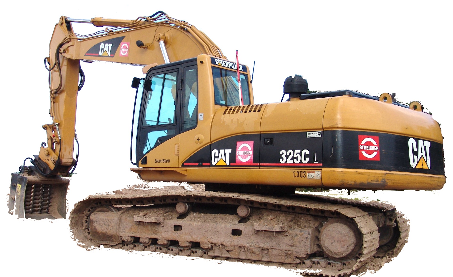
Complete workshop & service manual with electrical wiring diagrams for Caterpillar 330, 330L & 330 LN Excavators. It’s the same service manual used by dealers that guaranteed to be fully functional and intact without any missing page.

This Caterpillar 330, 330L & 330 LN Excavators service & repair manual (including maintenance, overhaul, disassembling & assembling, adjustment, tune-up, operation, inspecting, diagnostic & troubleshooting…) is divided into different sections. Each section covers a specific component or system with detailed illustrations. A table of contents is placed at the beginning of each section. Pages are easily found by category, and each page is expandable for great detail. The printer-ready PDF documents work like a charm on all kinds of devices.

MANUAL LIST:
SENR5497 – Schematic (330 Excavators Hydraulic System).pdf
SENR5496 – Testing & Adjusting (330, 330L & 330 LN Excavators Hydraulic & Electronic Sys)
SENR5498 – Disassembly & Assembly (330, 330 L & 330 LN Excavators Machine Systems)
SENR5499 – Schematic (330 Excavator Electrical System)
SENR5557 – Disassembly & Assembly (3306 Engine Supplement for 330, 330L, & 330 LN Excavators)
SENR5495 – Systems Operation (330, 330 L & 330 LN Excavators Hydraulic System).pdf
SENR5493 – Specifications (330, 330L & 330LN Excavators Hydraulic System)

EXCERPT:
a. Move the control levers for the boom, bucket, stick and swing through their full travel strokes. This will relieve any pressure that may be present in the pilot system.
b. Slowly loosen the air breather cap on the hydraulic oil tank to release the pressure.
c. Tighten the air breather cap on the hydraulic oil tank.
d. Tighten the air breather cap on the hydraulic oil tank.
e. The pressure in the hydraulic system has now been released. Lines and components can now be removed.
9. Disconnect four hose assemblies (5) for the stick cylinder. Put plugs in the ends of the hose assemblies to keep dirt and debris out of the hydraulic system. Disconnect wiring harness (6) for the boom lights.
10. Remove hand rail (7) from the machine. This will provide the necessary clearance for removal of the pin assembly which holds the boom to the main frame of the machine.
11. Remove pin assembly retaining bolt (9) and the washer that holds pin assembly (8) in place.


INSTANT DOWNLOAD


Posted on

Caterpillar 325C & 325C L Excavators Factory Service Repair Manual & Parts Manual


INSTANT DOWNLOAD


Complete workshop & service manual with electrical wiring diagrams for Caterpillar 325C & 325C L Excavators. It’s the same service manual used by dealers that guaranteed to be fully functional and intact without any missing page.

This Caterpillar 325C & 325C L Excavators service & repair manual (including maintenance, overhaul, disassembling & assembling, adjustment, tune-up, operation, inspecting, diagnostic & troubleshooting…) is divided into different sections. Each section covers a specific component or system with detailed illustrations. A table of contents is placed at the beginning of each section. Pages are easily found by category, and each page is expandable for great detail. The printer-ready PDF documents work like a charm on all kinds of devices.

MANUAL LIST:
SEBP3153 – Parts Manual (325C & 325C L Excavators, Powered By 3126B Engine)
RENR3763 – Specifications (312C, 315C, 318C, 319C, 320C, 322C, 325C and 330C Excavators Air Conditioning and Heating)
RENR3763 – Systems Operation (312C, 315C, 318C, 319C, 320C, 322C, 325C and 330C Excavators Air Conditioning and Heating)
RENR3763 – Testing and Adjusting (312C, 315C, 318C, 319C, 320C, 322C, 325C and 330C Excavators Air Conditioning and Heating)
RENR3814 – Systems Operation (312C, 315C, 318C, 319C, 320C, 321C, 322C, 325C, 330C, M325C, 325C MHPU, 330C MHPU Mobile Hydraulic Power Units Engine and Pump Control – V2)
RENR3814 – Testing & Adjusting (312C, 315C, 318C, 319C, 320C, 321C, 322C, 325C, 330C, M325C, 325C MHPU, 330C MHPU Mobile Hydraulic Power Units Engine and Pump Control – V2)
RENR5363 – Specifications (325C Excavator Machine System)
RENR5364 – Systems Operation (325C Excavator Hydraulic System)
RENR5365 – Testing and Adjusting (325C Excavator Hydraulic System)
RENR5366 – Schematic (325C Excavator Hydraulic System)
RENR5367 – Disassembly & Assembly (325C Excavator Machine Systems)
RENR5368 – Disassembly & Assembly (325C Excavator 3126B Engine Supplement)
RENR5369 – Schematic (325C Excavator Electrical System)

EXCERPT:
3. Install sheet (1). Install bolts (2).
4. If the hydraulic accumulator was disassembled, use Tooling (B) to recharge the hydraulic accumulator.
5. Check the oil level in the hydraulic oil tank. Fill the hydraulic oil tank with oil to the correct level.
Refer to the Operation and Maintenance Manual, “Lubricant Viscosities” for the proper oil
viscosity. Refer to the Operation and Maintenance Manual, “Hydraulic System Oil Level – Check” for the correct filling procedure.
6. Install high efficiency filters in place of the pilot filter, the case drain filter, and the return filter.
Note: High efficiency filters should not be run for more than 250 hours before you change back to the standard filters.
7. Obtain a hydraulic oil sample from the main S·O·S port.
Reference: Refer to Operation and Maintenance Manual, “Sampling Interval and Location of Sampling Valve” for the correct location.
8. If the S·O·S sample exceeds ISO 18/15, flush the hydraulic system.
Reference: Refer to Contamination Control Guidelines, SEBF8436, “Hydraulic System Flushing Procedure for 320C Hydraulic Excavators” for further information.


INSTANT DOWNLOAD


Posted on

Caterpillar Excavators 320D/320D L/323D Factory Service & Shop Manual


INSTANT DOWNLOAD


Complete workshop & service manual with electrical wiring diagrams for Caterpillar Excavators 320D, 320D L, 323D. It’s the same service manual used by dealers that guaranteed to be fully functional and intact without any missing page.

This Caterpillar Excavators Caterpillar Excavators 320D, 320D L, 323D service & repair manual (including maintenance, overhaul, disassembling & assembling, adjustment, tune-up, operation, inspecting, diagnostic & troubleshooting…) is divided into different sections. Each section covers a specific component or system with detailed illustrations. A table of contents is placed at the beginning of each section. Pages are easily found by category, and each page is expandable for great detail. The printer-ready PDF documents work like a charm on all kinds of devices.

MANUAL LIST:
KENR6098 – Schematic (320D Excavator Hydraulic System – Attachment)
KENR6099 – Schematic (320D and 323D Excavator Hydraulic System – Attachment)
KENR6113 – Schematic (320D Excavator Hydraulic System – Attachment)
KENR6115 – Schematic (320D Excavator Hydraulic System – Attachment)
KENR6118 – Schematic (320D Excavator Electrical System)
KENR6119 – Schematic (320D and 323D Excavator Hydraulic System – Attachment)
KENR6120 – Schematic (323D Excavator Hydraulic System – Attachment)
KENR6121 – Schematic (323D Excavator Hydraulic System – Attachment)
KENR6122 – Schematic (320D, 321D, 323D, 324D, 325D, 329D, 330D, 336D, 336D2, 336D MHPU Excavator Hydraulic System – Attachment)
KENR6123 – Schematic (323D Excavator Hydraulic System – Attachment)
KENR8645 – Schematic (320D, 322D, 323D, 324D, 325D, 329D, 330D, 336D2 & 340D2 Excavator Electrical System)
RENR7149 – Schematic (320D & 323D Excavator Hydraulic System – Attachment)
RENR7156 – Schematic (320D and 323D Excavator Hydraulic System)
RENR7157 – Schematic (320D and 323D Excavator Hydraulic System – Attachment)
RENR7244 – Schematic (323D Excavator Hydraulic System – Attachment)
RENR7293 – Specifications (320D and 323D Excavators Machine System Specifications)
RENR7294 – Systems Operation (320D and 323D Excavators Hydraulic System)
RENR7295 – Testing and Adjusting (320D and 323D Excavators Hydraulic System)
RENR7296 – Schematic (320D and 320D L Excavator Hydraulic System)
RENR7404 – Schematic (320D and 323D Excavator Hydraulic System – Attachment)
RENR7439 – Schematic (320D and 323D Excavator Hydraulic System – Attachment)
RENR7500 – Disassembly & Assembly (323D Excavator Machine Systems)
RENR8614 – Disassembly and Assembly (320D Excavator Machine Systems)
RENR8650 – Disassembly and Assembly (320D Excavator C6.4 Engine Supplement)
RENR9104 – Schematic (320D Excavator Hydraulic System – Attachment)
RENR9107 – Schematic (320D Excavator Hydraulic System – Attachment)
RENR9209 – Disassembly and Assembly (323D Excavator 3066 Engine Supplement)
RENR9896 – Schematic (323D Excavator Hydraulic System)
RENR9897 – Schematic (323D Excavator Electrical System)
RENR9972 – Schematic (323D Excavator Hydraulic System – Attachment)
RENR9998 – Schematic (323D Excavator Hydraulic System – Attachment)
SEBP4874 – Parts Manual (320D & 320D L Excavators)
SENR5664 – Disassembly & Assembly (Air Conditioning & Heating R134a for All Caterpillar Machines)
SENR5664 – Specifications (Air Conditioning & Heating R134a for All Caterpillar Machines)
SENR5664 – Systems Operation (Air Conditioning & Heating R134a for All Caterpillar Machines)
SENR5664 – Testing & Adjusting (Air Conditioning & Heating R134a for All Caterpillar Machines)
SENR5664 – Troubleshooting (Air Conditioning & Heating R134a for All Caterpillar Machines)
SENR6572 – Disassembly & Assembly (Zexel Fuel System)
UENR2514 – Schematic (320D Excavator Hydraulic System – Attachment)
UENR3685 – Schematic (320D Excavator Electrical System)
UENR5820 – Schematic (320D Excavator Electrical System)
KENR6122 – Schematic (320D, 321D, 323D, 324D, 325D, 330D Excavator Hydraulic System – Attachment).pdf
SENR6572 – Systems Operations (Zexel Fuel System).pdf
SENR6572 – Testing & Adjusting (Zexel Fuel System).pdf

EXCERPT:
Auxiliary Pilot Valve (Straight Travel) – Disassemble
Disassembly Procedure
Start By:
a. Remove the auxiliary pilot control valve. Refer to Disassembly and Assembly, “Auxiliary Pilot Valve (Straight Travel) – Remove”.
Note: Cleanliness is an important factor. Before the disassembly procedure, the exterior of the component should be thoroughly cleaned. This will prevent dirt from entering the internal mechanism.
Note: During the disassembly of the auxiliary pilot control valve, put identification marks on each component for assembly purposes.
1. Remove bellows (1) from the pilot valve.

Fuel Pump Housing
SMCS – 1253-015; 1253-016
Disassemble Fuel Injection Pump Housing
Start By:
a. separate governor from fuel injection pump housing
NOTE: Clean the outside of the fuel injection pump before disassembly and drain the pump camshaft chamber.
1. Remove three nuts (1) and washers.
2. Remove fuel priming and transfer pump (2). For details on disassembly and assembly of the fuel priming and transfer pump see the topic “Disassemble and Assemble Fuel Priming and Transfer Pump” in this module.
3. Check O-ring seal (3) on fuel priming and transfer pump (2). Replace if necessary.
4. Remove two bolts (4) and washers.
5. Remove cover (5). Remove the gasket on the back of cover (5).
6. Install Tool (D) to rotate the camshaft until the tappets are in the top center position.
7. Insert Tool (N), (tappet holders) into the small holes (6) on the tappet body to separate the tappet from the camshaft.
8. Rotate the fuel injection pump housing on its side and remove six screws plugs (7).
9. Remove two center bearing screws (8) with a screwdriver.
10. Rotate the camshaft until the key groove is facing up, remove Tool (D), use Tools (L and K) to remove Tool (D).
11. Remove four bearing cover bolts (9).
12. Tap the camshaft lightly from the governor end with a soft hammer to loosen bearing cover (10).
Remove bearing cover (10).


INSTANT DOWNLOAD


Posted on

Caterpillar 320C/322C Excavator Factory Service & Shop Manual


INSTANT DOWNLOAD


Complete workshop & service manual with electrical wiring diagrams for Caterpillar 320C/322C Excavator. It’s the same service manual used by dealers that guaranteed to be fully functional and intact without any missing page.

This Caterpillar 320C/322C Excavator service & repair manual (including maintenance, overhaul, disassembling & assembling, adjustment, tune-up, operation, inspecting, diagnostic & troubleshooting…) is divided into different sections. Each section covers a specific component or system with detailed illustrations. A table of contents is placed at the beginning of each section. Pages are easily found by category, and each page is expandable for great detail. The printer-ready PDF documents work like a charm on all kinds of devices.

Manual List:
RENR3763 – Specifications (312C, 315C, 318C, 319C, 320C, 322C, 325C and 330C Excavators Air Conditioning & Heating)
RENR3763 – Systems Operation (312C, 315C, 318C, 319C, 320C, 322C, 325C and 330C Excavators Air Conditioning & Heating)
RENR3763 – Testing & Adjusting (312C, 315C, 318C, 319C, 320C, 322C, 325C and 330C Excavators Air Conditioning & Heating)
RENR3813 – Disassembly & Assembly (320C Excavator Engine Supplement)
RENR3814 – Systems Operation (MHPU and 330C MHPU Mobile Hydraulic Power Units Engine and Pump Control – V2)
RENR3814 – Testing & Adjusting (MHPU and 330C MHPU Mobile Hydraulic Power Units Engine and Pump Control – V2)
RENR3815 – Specifications (320C Excavator Machine System Specifications)
RENR3816 – Systems Operation (320C Excavator Hydraulic System)
RENR3817 – Testing & Adjusting (320C Excavator Hydraulic System)
RENR3818 – Systems Operation (320C and 322C Excavators Attachment Hydraulic System)
RENR3818 – Testing & Adjusting (320C and 322C Excavators Attachment Hydraulic System)
RENR3819 – Schematic (320C Excavator Hydraulic System)
RENR3820 – Schematic (320C Excavators Hydraulic System (Attachment) Quick Coupler)
RENR3821 – Schematic (320C Excavator Electrical System)
RENR3822 – Schematic (320C Excavator Electrical System)
RENR3823 – Systems Operation (320C, 322C and 325C Excavators Tool Control System)
RENR3823 – Testing & Adjusting (320C, 322C and 325C Excavators Tool Control System)
RENR3823 – Troubleshooting (320C, 322C and 325C Excavators Tool Control System)
RENR3826 – Disassembly and Assembly (320C Excavator Machine Systems)
RENR3829 – Schematic (320C, 322C Excavators Stick Lowering Control Valve Hydraulic System – Attachment)
RENR3847 – Schematic (320C U Excavator Electrical System)
RENR3886 – Schematic (320C Excavators Hydraulic System (Attachment) System 1 One Way/One Pump Flow/Hydraulic Foot Pedal)
RENR3888 – Schematic (320C Excavators Hydraulic System (Attachment) System 14 Combined Function/Auxiliary Pump)
RENR3893 – Schematic (320C Excavator Hydraulic System – Attachment)
RENR3895 – Testing & Adjusting (320C Excavator Hydraulic System)
RENR7159 – Schematic (320C Excavator Hydraulic System – Attachment)
RENR7269 – Schematic (320C Excavator Hydraulic System (Attachment) VA Boom)

EXCERPT:
Note: A hydraulic oil sample should be obtained before any maintenance is performed in order to establish the system contaminant level. Refer to Fluid Analysis Laboratory Guide, SEBF3116,
“Obtaining an Oil Sample for S·O·S Analysis”. Refer to Operation and Maintenance Manual,
“Sampling Interval and Location of Sampling Valve” for the correct location.
1. Release the pressure in the hydraulic system.
ReferenceRefer to Disassembly and Assembly, “Hydraulic System Pressure – Release” in this manual.
2. Drain the hydraulic oil tank into a suitable container for storage or disposal. The capacity of the hydraulic oil tank is 120 L (32 US gal).
ReferenceRefer to Operation and Maintenance, “Hydraulic System Oil – Change” in the service manual.


INSTANT DOWNLOAD


Posted on

Caterpillar 320, 320L, 320N Excavator Factory Service & Shop Manual


INSTANT DOWNLOAD


Complete workshop & service manual with electrical wiring diagrams for Caterpillar 320, 320 L, 320 N Excavator. It’s the same service manual used by dealers that guaranteed to be fully functional and intact without any missing page.

This Caterpillar 320, 320L, 320N Excavator service & repair manual (including maintenance, overhaul, disassembling & assembling, adjustment, tune-up, operation, inspecting, diagnostic & troubleshooting…) is divided into different sections. Each section covers a specific component or system with detailed illustrations. A table of contents is placed at the beginning of each section. Pages are easily found by category, and each page is expandable for great detail. The printer-ready PDF documents work like a charm on all kinds of devices.

MANUAL LIST:
SENR5453 – Specifications (320, 320L, 320N & 320S Excavator Hydraulic System)
SENR5454 – Disassembly & Assembly (320 & 320 L Excavators Vehicle Systems)
SENR5457 – Schematic (320 & 320L Excavator Hydraulic System)
SENR5458 – Disassembly & Assembly (320, 320 L & 320 N Excavators Vehicle Systems)
SENR5459 – Schematic (320, 320L, 320N, and 320S Excavators Electrical System)
SENR5474 – Specifications (320 & 320 L Excavators Hydraulic System)
SENR5494 – Disassembly & Assembly (Main Hydraulic Pump & Pilot Pump Supplement for 320 & 320 L)
SENR5556 – Disassembly & Assembly (Supplement for 320 & 320 L Excavators (3066 Engine))
SENR6090 – Specifications (320 & 320 L Excavator Attachments)
SENR6093 – Schematic (320 & 320 L Excavators Hydraulic System – Double Action, One Pump (Attachment))
SENR6095 – Schematic (320 & 320 L Excavators Hydraulic System – Attachment)
SENR6096 – Schematic (320 & 320 L Excavators Hydraulic System Boom Lowering Check (Attachment))
SENR6097 – Schematic (320 Excavators Hydraulic System – Attachment)
SENR5455 – Systems Operation (320, 320 L & 320 N Excavators Hydraulic System).pdf
SENR5460 – Systems Operation (320 & 320 L Excavators Attachments).pdf
SENR5460 – Testing & Adjusting (320 & 320 L Excavators Attachments).pdf
SENR5461 – Schematic (320, 320 L & 320 N Excavators Hydraulic System).pdf
SENR5463 – Systems Operation (320, 320L Excavators Electronic & Electrical System).pdf
SENR5464 – Systems Operation (320, 320 L & 320 N Excavators Hydraulic System).pdf
SENR5473 – Testing & Adjusting (320 & 320L Excavators Hydraulic And Electronic Systems).pdf
SENR6091 – Schematic (320 & 320 L Excavators Hydraulic System – Single Action, One Pump (Attachment)).pdf
SENR6092 – Schematic (320 & 320 L Excavators Hydraulic System – Attachment).pdf
SENR6094 – Schematic (320 & 320 L Excavators Hydraulic System – Common Piping, Two Pumps (Attachment)).pdf

EXCERPT:
Disassemble & Assemble Final Drives
Start By:
a. remove final drives
1. Thoroughly clean the outside of the final drive prior to disassembly.
2. Remove the travel brake valve and the travel motor from the final drive. See the topics “Remove & Install Travel Brake Valves” and “Remove & Install Travel Motors” in this module.
3. Put an alignment mark across the sections of the final drive for assembly purposes. The parts must be reinstalled in their original locations.


INSTANT DOWNLOAD