INSTANT DOWNLOAD (add to cart)
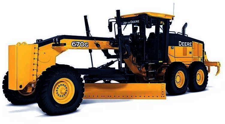
John Deere 670G, 670GP, 672G, 672GP Motor Graders Operation & Test Technical Manual (TM13065X19)
TM13065X19 – 670G, 670GP, 672G, 672GP Motor Graders Operation & Test Manual.pdf
1,530 pages, bookmarked, Searchable, Printable, high quality PDF
Complete technical Operation & Test Manual with electrical wiring diagrams for John Deere 670G, 670GP, 672G, 672GP Motor Graders. It’s the same service manual used by dealers that guaranteed to be fully functional and intact without any missing page.
John Deere 670G, 670GP, 672G, 672GP Motor Graders Operation & Test Technical Manual (including maintenance, overhaul, disassembling & assembling, adjustment, tune-up, operation, inspecting, diagnostic & troubleshooting…) is divided into different sections. Each section covers a specific component or system with detailed illustrations. A table of contents is placed at the beginning of each section. Pages are easily found by category, and each page is expandable for great detail. The printer-ready PDF documents work like a charm on all kinds of devices.
CONTENTS
9000 – General Information
9001 – Diagnostic Trouble Codes (DTC)
9005 – Operational Checkout Procedure
9010 – Engine
9015 – Electrical System
9016 – Six Wheel Drive (6WD)
9020 – Power Train
9025 – Hydraulic System
9031 – Heating and Air Conditioning
…