INSTANT DOWNLOAD (add to cart)
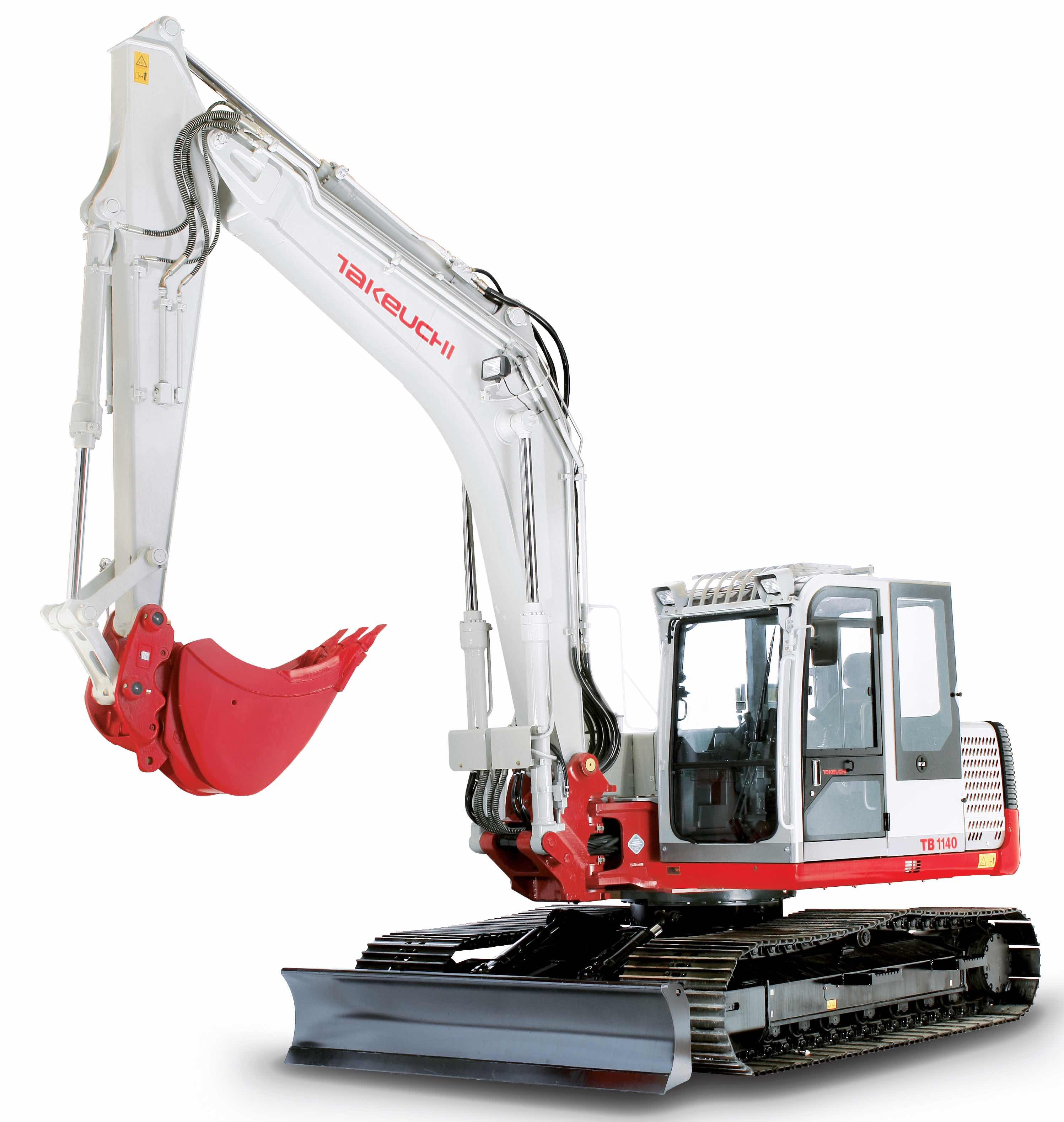
Complete workshop & service manual with electrical wiring diagrams for Takeuchi Compact Excavator TB1140. It’s the same service manual used by dealers that guaranteed to be fully functional and intact without any missing page.
This Takeuchi Compact Excavator TB1140 service & repair manual (including maintenance, overhaul, disassembling & assembling, adjustment, tune-up, operation, inspecting, diagnostic & troubleshooting…) is divided into different sections. Each section covers a specific component or system with detailed illustrations. A table of contents is placed at the beginning of each section. Pages are easily found by category, and each page is expandable for great detail. The printer-ready PDF documents work like a charm on all kinds of devices.
652 pages, bookmarked, Searchable, Printable, high quality PDF
Takeuchi Compact Excavator TB1140 Workshop Manual; 652 pages; Serial Number: 51400007~.
EXCERPT:
I . GENERAL
II . SPECIFICATIONS
III. MACHINE CONFIGURATION
IV . HYDRAULIC UNITS
V . TROUBLESHOOTING VI. ENGINE
…
UPPER FRAME – MACHINE CONFIGURATION
Removing the Cab
1. Disconnect the battery ground cable from the battery.
2. Remove the operator seat from the bracket.
3. Remove the cover R (1), L (2) and C (3), then remove bracket (4) from cover C (3).
4. Remove the cover R (5), then disconnect the speaker cords.
5. Remove the cover L (6), then disconnect the speaker cords and duct hose (7) from cover L (6).
6. Remove the duct hose (8) from air conditioner unit (9)
7. Remove the installation bolts, remove the box (10) from cab.
8. Disconnect the wiring (11) to the cab.
9. Disconnect the hose (12) from sub tank.
10. Loosen the seat bracket installation bolts (13) [four].
11. Remove installation bolts (14) [six], then hoist and remove the cab.
• Be sure to hoist the cab carefully by sliding the seat so as not to hit the cab. Cab: 370 kg
Installing the Cab
Follow the procedure used for removal in reverse order.
• Suspend the cab temporarily, keeping it level, and fasten it temporarily while it is still suspended.
…