Posted on

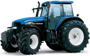
New Holland TM Series Tractors (TM120, TM130, TM140, TM155, TM175, TM190) Factory Service & Shop Manual


Download Link

INSTANT DOWNLOAD (add to cart)


1C056

Complete workshop & service manual with electrical wiring diagrams for New Holland TM Series Tractors (TM120, TM130, TM140, TM155, TM175, TM190). It’s the same service manual used by dealers that guaranteed to be fully functional and intact without any missing page.

This New Holland TM Series Tractors (TM120, TM130, TM140, TM155, TM175, TM190) service & repair manual (including maintenance, overhaul, disassembling & assembling, adjustment, tune-up, operation, inspecting, diagnostic & troubleshooting…) is divided into different sections. Each section covers a specific component or system with detailed illustrations. A table of contents is placed at the beginning of each section. Pages are easily found by category, and each page is expandable for great detail. The printer-ready PDF documents work like a charm on all kinds of devices.

4,377 pages, bookmarked, Searchable, Printable, high quality PDF
New Holland TM Series Tractors (TM120, TM130, TM140, TM155, TM175, TM190) Repair Manual.pdf
604.55.111.00 – 06 – 2002

EXCERPT:
SECTION 21 – TRANSMISSION SYSTEMS – CHAPTER 1
Tool to be fabricated for range input shaft bearing assembly (Mark tool with no. 50060 – Dimensions in mm.)
Fabricate tool using C30 material.
Bracket to be fabricated to fix the transmission on the rotary stand. Use with bracket tool no. 293971 (Mark tool with no. 50110 – Dimensions in mm). Fabricate tool using Fe 42 C material.
Tool to be fabricated for input and output shaft bearing assembly (Mark tool with no. 50108 – Dimensions in mm).
Fabricate tool using UNI C40 material.
Alignment pins to be fabricated for engine and speed clutch/transmission housing removal/installation (Mark tool with no. 50117 – Dimensions in mm).
Fabricate tool using UNI C40 material.
Adapter to be fabricated for reverse idler gear pin removal (Mark tool with no. 50143 – Dimensions in mm).
Fabricate tool using UNI C40 material.

Posted on

New Holland TJ275, TJ325, TJ375, TJ375HD, TJ450 Tractors Factory Service & Shop Manual


Download Link

INSTANT DOWNLOAD (add to cart)

Complete workshop & service manual with electrical wiring diagrams for New Holland TJ Series Tractors TJ275, TJ325, TJ375, TJ375HD, TJ450. It’s the same service manual used by dealers that guaranteed to be fully functional and intact without any missing page.

This New Holland TJ275, TJ325, TJ375, TJ375HD, TJ450 service & repair manual (including maintenance, overhaul, disassembling & assembling, adjustment, tune-up, operation, inspecting, diagnostic & troubleshooting…) is divided into different sections. Each section covers a specific component or system with detailed illustrations. A table of contents is placed at the beginning of each section. Pages are easily found by category, and each page is expandable for great detail. The printer-ready PDF documents work like a charm on all kinds of devices.

6,020 pages, bookmarked, Searchable, Printable, high quality PDF
New Holland TJ Series Tractors (TJ275, TJ325, TJ375, TJ375HD, TJ450) Repair Manual
6,020 pages, 682.6 MB PDF

COMPLETE CONTENTS
SECTION00-GENERALINFORMATION … 2
SECTION10-ENGINES … 5
SECTION21-TRANSMISSIONS … 93
SECTION31-POWERTAKE-OFF .. 101
SECTION33-BRAKESANDCONTROLS … 105
SECTION35-HYDRAULICSYSTEMS .. 107
SECTION37-TOWINGHOOKSANDBALLASTING.. 122
SECTION39-FRAMES.. 123
SECTION41-STEERING .. 124
SECTION44-AXLESANDWHEELS … 128
SECTION50-CABCLIMATECONTROL .. 136
SECTION55-ELECTRICALSYSTEMS … 142
SECTION90-PLATFORMANDCAB … 169

The following pages are the collation of the contents pages from each section and chapter of the TJ Series Repair manual.
The sections used through out all New Holland product Repair manuals may not be used for each product. Each Repair manual will be made up of one or several books. Each book will be labeled as to which sections are in the overall Repair manual and which sections are in each book.
The sections listed above are the sections utilized for the TJ Series Tractors.

EXCERPT:
Section 10 Chapter 1
ENGINE REMOVAL AND INSTALLATION TJ 275 – 325
STEP 1
1. Park the tractor on a solid, level surface.
2. Place the shift lever in PARK (Powershift) or place the shift levers in neutral and the park brake switch in the ON position.
3. Shut off the engine and remove the key from the switch.
STEP 2
Discharge the A/C system. See Section 50, Chapter 2 of the Service Manual for discharge procedures.
STEP 3
Remove the hood. See Section 90, Chapter 3 of the Service Manual for hood removal procedures.
STEP 4
Remove the radiator. See Section 10, Chapter 4 for radiator removal procedures.
STEP 5
Open the battery access door and disconnect the negative battery cables from both batteries.
STEP 6
Loosen the clamps and remove the aspirator tube from the check valve and air cleaner.
STEP 7
Remove the wire harness connector from the restriction switch.
STEP 8
Remove the RH wire harness clamp from the hood support.
STEP 9
Remove the two LH wire harness clamps.
STEP 10
Loosen the two carriage bolt (1) nuts and remove the two rear mounting bolts (2), washers and nuts. Remove the frame step.

Posted on

New Holland TG Series Tractors (TG210, TG230, TG255, TG285) Factory Service & Shop Manual


Download Link

INSTANT DOWNLOAD (add to cart)


Complete workshop & service manual with electrical wiring diagrams for New Holland TG Series Tractors (TG210, TG230, TG255, TG285). It’s the same service manual used by dealers that guaranteed to be fully functional and intact without any missing page.

New Holland TG Series Tractors (TG210, TG230, TG255, TG285) service & repair manual (including maintenance, overhaul, disassembling & assembling, adjustment, tune-up, operation, inspecting, diagnostic & troubleshooting…) is divided into different sections. Each section covers a specific component or system with detailed illustrations. A table of contents is placed at the beginning of each section. Pages are easily found by category, and each page is expandable for great detail. The printer-ready PDF documents work like a charm on all kinds of devices.

3,098 pages, bookmarked, Searchable, Printable, high quality PDF

New Holland TG Series Tractors (TG210, TG230, TG255, TG285) Repair Manual
3,098 pages, 708 MB PDF
87057613 Issued 11-02 / Revised 01-05

COMPLETE TABLE OF CONTENTS
Standard Torque Specifications
Safety, General Information/Maintenance Schedule
General Specifications and Special Torques
Engine Removal and Installation
Fuel Tank Removal and Installation
Radiator, Coolers and Condenser – Removal and Installation
8.3L, 24 Valve Engine Introduction
8.3L, 24 Valve Engine Identification
8.3L, 24 Valve Engine Troubleshooting Symptoms
8.3L, 24 Valve Engine Cylinder Block
8.3L, 24 Valve Engine Cylinder Head
8.3L, 24 Valve Engine Rocker Levers
8.3L, 24 Valve Engine Cam Followers
8.3L, 24 Valve Engine Fuel System
8.3L, 24 Valve Engine Injectors and Fuel Lines
8.3L, 24 Valve Engine Lubricating Oil System
8.3L, 24 Valve Engine Cooling System
8.3L, 24 Valve Engine Drive Units
8.3L, 24 Valve Engine Air Intake System
8.3L, 24 Valve Engine Exhaust System
8.3L, 24 Valve Engine Miscellaneous
8.3L, 24 Valve Engine Specifications
8.3L, 24 Valve Engine Fuel System – Introduction
8.3L, 24 Valve Engine Fuel System – System Identification
8.3L, 24 Valve Engine Fuel System – Familiarization
8.3L, 24 Valve Engine Fuel System – Troubleshooting Fault Codes
8.3L, 24 Valve Engine Fuel System – Troubleshooting Symptoms
8.3L, 24 Valve Engine Fuel System – Electronic Engine Controls
8.3L, 24 Valve Engine Fuel System – Specifications
Viscous Fan Drive Test (Service Bulletin)
Power Take Off Control System How it Works
Powershift Transmission System How it Works and Troubleshooting
Front Frame to Speed Transmission Split
Speed to Range Transmission Split
Speed Transmission
Range Transmission to Rear Frame Split
Range Transmission
Transmission Control Valves and inching Valve
Rear Frame
Hydraulic Pump Drive
Mechanical Front Drive MFD Control System How it Works
Differential Lock Control System How it Works
MFD Clutch Removal Without Tractor Split
MFD Driveshaft Removal and Installation
Suspended MFD Axle Removal
Supersteer Axle Removal
Limited Slip FWD Differential
Locking MFD Differential
MFD Planetary Hub, Steering Knuckle, and Axle Drive Shaft
Suspended FWD Axle
Supersteer Axle Vertical Control Linkage
Suspended FWD Axle System
Rear Axle and Planetaries
Brake Valve
Brake Cylinders
Park Brake
Trailer Brakes How It Works
How to Read Symbols in a Hydraulic Schematic
Hydraulic Systems How it Works and Troubleshooting
PTO and Differential Lock Valve
Remote Valve and Coupler Service
Remote Hydraulic System How it Works and Troubleshooting
Priority and Regulator Valve
Charge Pump
CCLS Piston Pump And Hydraulic Filter
Hitch System How it Works
Hitch Control Valve
Air Conditioning Troubleshooting
Air Conditioner System Service
Electrical System How It Works and Troubleshooting (Prior to P.I.N. JAW 129992)
Standard Instrumentation Programming and Fault Codes
Hitch Controller Calibration and Fault Codes
Transmission Controller
(With Suspended Axle) Calibration and Fault Codes
Armrest Controller Calibration and Fault Codes
Remote Hydraulics Controller Fault Codes
PTO Controller Configuration and Fault Codes
Performance Monitor Controller Fault Codes
Pedal and Pedal Switch Adjustment
Cab Raise/Removal and Installation
Service Information packaged with 87012641
INSITE Professional – Operation / ESDN – ECM Software Installation – 87012632 Electronic Service Tool – Users Guide 87025502
Electrical Schematic (Prior to P.I.N. JAW129992) – 87025177
Electrical Schematic (P.I.N. JAW129992 and After) – 87054643
Hydraulic Schematic – 87025178 Loctite Product Chart – 8-98902

EXCERPT:
24 Valve, 8.3 Liter Engine Miscellaneous
Cup Plug (017-002)
Remove (017-002-002)
Use a center punch to mark the cup plug for drilling.
CAUTION
Do not allow metal shavings to fall in the engine when drilling a hole in the cup plug. Damage to engine components can occur.
Drill an 1/8-inch hole into the cup plug.
Use a dent puller to remove the plug.
Discard all used cup plugs. Do not use them again.
Cup Plug (017-002)
Clean (017-002-006)
Thoroughly clean the cup plug hole using Scotch-Brite, or equivalent. Use spray cleaner or equivalent, to perform a final clean of the bore.
Inspect for Reuse (017-002-007)
Inspect the cup plug bores for damage.

Posted on

New Holland TD5040, TD5050 Factory Service & Shop Manual


Download Link

INSTANT DOWNLOAD (add to cart)


Complete workshop & service manual with electrical wiring diagrams for New Holland TD5040, TD5050. It’s the same service manual used by dealers that guaranteed to be fully functional and intact without any missing page.

New Holland TD5040, TD5050 service & repair manual (including maintenance, overhaul, disassembling & assembling, adjustment, tune-up, operation, inspecting, diagnostic & troubleshooting…) is divided into different sections. Each section covers a specific component or system with detailed illustrations. A table of contents is placed at the beginning of each section. Pages are easily found by category, and each page is expandable for great detail. The printer-ready PDF documents work like a charm on all kinds of devices.

598 pages, bookmarked, Searchable, Printable, high quality PDF

New Holland TD Series Tractors (TD5040, TD5050) Repair Manual
598 pages PDF
Print No. 87749051 – 11 – 2007

EXCERPT:

SECTION 27 – REAR AXLE AND TRANSMISSION – CHAPTER 1

TRANSMISSION-GEARBOX CASE
Removal-Refitting (Op. 21 118 85)

WARNING
Handle all parts with great care. Never place your hands or fingers between one part and another. Wear the prescribed safety clothing, including glasses, gloves and protective footwear.

1. Secure the transmission box-gearbox to the rotating stand 290090 using the front 293972 and rear 293971 mountings.

2. Turn the box by 180°, undo the bolts (1) and remove the transfer box (2).

3. Turn the box back 180°, then use a punch to remove the roll pins (1) and take out the rods, the prongs, the gearbox and final drive control forks.

4. Use a punch to remove the roll pin (2) retaining the differential lock engagement fork (1). With- draw the rod (4) and remove the helical spring (3) and the fork.

Posted on

New Holland TD60D, TD70D, TD80D, TD90D, TD95D Model Tractors Factory Service & Shop Manual


Download Link

INSTANT DOWNLOAD (add to cart)


Complete workshop & service manual with electrical wiring diagrams for New Holland TD60D, TD70D, TD80D, TD90D, TD95D Model Tractors. It’s the same service manual used by dealers that guaranteed to be fully functional and intact without any missing page.

This New Holland TD60D, TD70D, TD80D, TD90D, TD95D Model Tractors service & repair manual (including maintenance, overhaul, disassembling & assembling, adjustment, tune-up, operation, inspecting, diagnostic & troubleshooting…) is divided into different sections. Each section covers a specific component or system with detailed illustrations. A table of contents is placed at the beginning of each section. Pages are easily found by category, and each page is expandable for great detail. The printer-ready PDF documents work like a charm on all kinds of devices.

608 pages, bookmarked, Searchable, Printable, high quality PDF
New Holland TD60D – TD70D – TD80D – TD90D – TD95D Model Tractors Service Manual
Part number 603.54.471.00− 11 − 2004

87592264- – TD60D, TD70D, TD80D, TD90D, TD95D Operator’s Manual.pdf

EXCERPT:

34 SECTION 35 − HYDRAULIC SYSTEM − CHAPTER 1

ADJUSTING LINKAGES (Op. 35 110 08)

Adjusting position control linkage

Proceed as follows.

1. Move the position control lever (1) fully forward on the quadrant and check that the distance (L) is between 15 and 20 mm (0.5906 and 0.7874 in.).

2. Move the external position control lever (1) fully rearward, against the spacer.

3. Connect the control linkage and adjust its length, if necessary.

4. Fasten the linkage using the lock nuts.

Adjusting draft control linkage

Test conditions:
− engine running at medium speed;
− allow the oil in the system to reach a temperature of 30 − 40 °C (86 − 104 °F).

Then proceed as follows:

5. Move the position control lever (1) fully forward on the quadrant and the draft control lever (2) to a distance (L1) of 15 − 20 mm (0.5906 − 0.7874 in.). from the beginning of the slot.

6. Move the draft control lever (2) fully back against the spacer.

7. Connect the control linkage and adjust its length if necessary.