Posted on

Case 60XT, 70XT Skid Steer Factory Service & Shop Manual


INSTANT DOWNLOAD (add to cart)


Case 60XT, 70XT Skid Steer Factory Service & Shop Manual
Complete workshop & service manual with electrical wiring diagrams for Case 60XT, 70XT Skid Steer. It’s the same service manual used by dealers that guaranteed to be fully functional and intact without any missing page.

This Case 60XT, 70XT Skid Steer service & repair manual (including maintenance, overhaul, disassembling & assembling, adjustment, tune-up, operation, inspecting, diagnostic & troubleshooting…) is divided into different sections. Each section covers a specific component or system with detailed illustrations. A table of contents is placed at the beginning of each section. Pages are easily found by category, and each page is expandable for great detail. The printer-ready PDF documents work like a charm on all kinds of devices.

653 + 237 pages, bookmarked, Searchable, Printable, high quality PDF

Case 60XT, 70XT Skid Steer Service Manual
Bur 6-45720, 653 pages

Case 60XT, 70XT Skid Steer Operator’s Manual
Bur 6-29451NA, 237 pages

EXCERPT:
Brake System Overview
(Spring Applied-Cable Release Park Brakes)
The 40XT, 60XT, and 70XT all use two spring applied, cable release, pin lock, parking brakes. The brakes are mounted to the chain tanks on the chassis in front of the right side hydraulic drive motor and behind the left side hydraulic drive motor.
The park brakes are activated when the seat restraint bar is raised from the operating position. The brake pins engage the slots in the brake disks and prevents it from turning and the 40, 60 and 70XT Skid Steer from moving. Also, when the seat restraint bar is lowered, the transmission control moves to neutral and prevents activation of the drive motors. The park brakes are released when the restraint bar is lowered to the operating position and the cable retracts the pins from the brake disk slots.
In the event of loss of power to the machine, the brakes may be released by lowering the restraint bar to the operating position.
1. RESTRAINT BAR IN LOCKOUT POSITION
2. RESTRAINT BAR IN OPERATING POSITION

Posted on

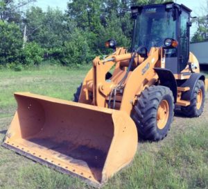
Case 21D, 121D, 221D, 321D Loaders Factory Technical Service & Shop Manual


Download Link

INSTANT DOWNLOAD (add to cart)


Complete workshop & service manual with electrical wiring diagrams for Case 21D, 121D, 221D, 321D. It’s the same service manual used by dealers that guaranteed to be fully functional and intact without any missing page.

Case Loaders 21D, 121D, 221D, 321D service & repair manual (including maintenance, overhaul, disassembling & assembling, adjustment, tune-up, operation, inspecting, diagnostic & troubleshooting…) is divided into different sections. Each section covers a specific component or system with detailed illustrations. A table of contents is placed at the beginning of each section. Pages are easily found by category, and each page is expandable for great detail. The printer-ready PDF documents work like a charm on all kinds of devices.

2,532 pages, bookmarked, Searchable, Printable, high quality PDF

FILE LIST:
9-93140 – Case 21D, 121D, 221D, 321D Manuel Technique (FR).pdf
9-93150- Case 21D, 121D, 221D, 321D Technic Handbook (EN).pdf
9-93160 – Case 21D, 121D, 221D, 321D Technisches Handbuch (DE).pdf

EXCERPT:
CHAPTER 01 – GENERAL
FOREWORD
This Technical Handbook (THB) has been written with the servicing mechanic in mind and contains important information required to carry out repair and servicing procedures.
Servicing and repair
Servicing and repair work should be carried out as soon as possible. This keeps overall servicing & repair costs to a minimum and increases the availabilily of the Wheel Loader.
Read through the Technical Handbook, but also the Operating Instructions for the Wheel Loader before commencing any servicing or repair work. The Technical Handbook, as well as the Operating Instructions and Spare Parts List should be used as a source of reference and assistance – even when the user is well acquainted with the range of the Wheel Loaders.
During servicing and repair work, always follow the instructions contained in the Technical Handbook and Operating instructions.
The After Sales Service is always available for assistance and advice.
Using the Technical Handbook allows the experienced mechanic to carry out repair work in a correct manner.
Using the Technical Handbook
The Technical Handbook is divided into main and sub-groups that deal with the machine as actually delivered. Any auxiliary attachments or optional upgrading introduced later are not described.
The main table of contents allows to find the required information quickly.
For the sake of clarity, the illustrations have been simplified and can therefore differ slightly from the actual appearance of the machine.