Posted on

Case 1150 Crawler Workshop Repair & Service Manual + Operator’s Manual


Download Link

INSTANT DOWNLOAD (add to cart)


total 1,000+ pages, bookmarked, Searchable, Printable, high quality PDF

“9-72483.pdf”
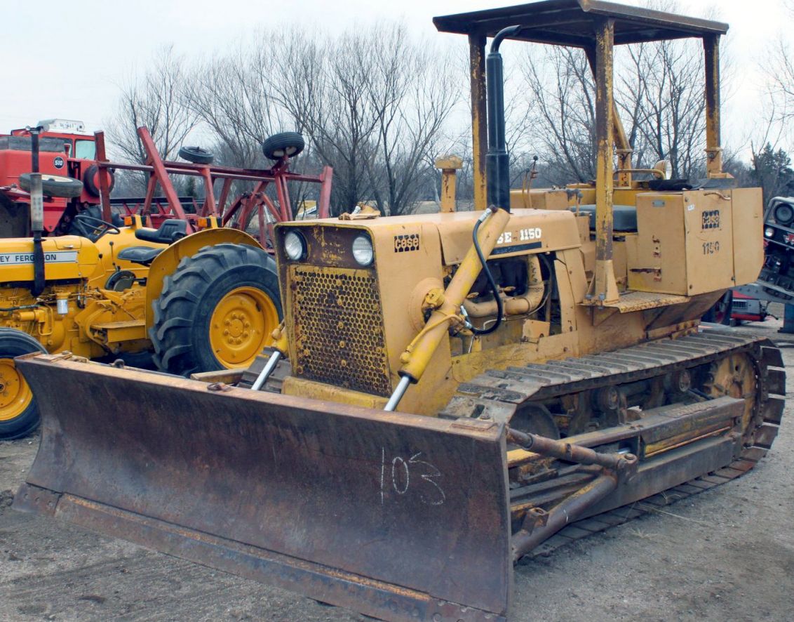
Case 1150 Crawler Service Manual
942 pages

“9-1733.pdf”
Case 1150 Crawler Operator’s Manual (S/N 7106801-7108998)
208 pages

“9-2082.pdf”
Case 1150 Crawler Operator’s Manual (S/N 7109000-7109299)

“9-2512.pdf”
Case 1150 Crawler Operator’s Manual (S/N 7110300-After)

Complete digital official shop manual contains service, maintenance, and troubleshooting information for the Case 1150 Crawler. Diagnostic and repair procedures are covered in great detail to repair, maintain, rebuild, refurbish or restore your Case 1150 Crawler like a professional mechanic in local service/repair workshop. This cost-effective quality manual is 100% complete and intact as should be without any missing pages. It is the same factory shop manual used by dealers that guaranteed to be fully functional to save your precious time.

This manual for Case 1150 Crawler is divided into different sections. Each section covers a specific component or system and, in addition to the standard service procedures, includes disassembling, inspecting, and assembling instructions. A table of contents is placed at the beginning of each section. Pages are easily found by category, and each page is expandable for great detail. It is in the cross-platform PDF document format so that it works like a charm on all kinds of devices. You do not need to be skilled with a computer to use the manual.

EXCERPT:
1150 CRAWLER
TABLE OF CONTENTS
1 GENERAL
General Engine Specifications (B401 Engine) ……….. 1010
Detailed Engine Specifications (B401 Engine) ………. 1022
Fuel System Specifications …………. 1030
Specifications for Case A401 Diesel Engines ………… CC
Section CC 9-76481 Supplement No.1 (Torques and Valve Timing) ….. Sup. 1
Specifications (General Tractor Specifications and Maintenance) …… I
2 ENGINES
General
Engine Removal (See Section IX in 90 Series)
Cooling System ………….. Ill
Engine Air Intake System …………….. IV
A401 Engine
Cylinder Heads, Valve Systems, Rocker Arms, Decompressor …. K
Engine Block ………………. M
Supplement- Servicing the Front Mounted Oil Pump ……. M
8401 Engine
Engine Diagnosis …………….. 2001
Engine Tune-Up ……………… 2002
Cylinder Head, Valve Train, Crankshaft ………. 2015
Cylinder Block, Sleeves, Pistons, Rods ………… 2025
Crankshaft, Main Bearings, Flywheel and Oil Seal ……. 2035
Lubrication System, Oil Pump, Heat Exchanger, Oil Flow Diagram …… 2046
Cooling System, Water Manifold, Water Pump, Thermostat …….. 2055
3 FUEL SYSTEM
Fuel Injectors- Case Powrcel Fuel Injection Pump (A401 Engine) …… I
Fuel System and Filters (B401 Engine) ………… 3010
Fuel Injection Pump (B401 Engine) ………. 3012
Fuel Injectors (B401 Engine) ……………. 3013
4 HYDRAULICS
Equipment Pump A16690, D35994 ………….. X
Equipment Pumps D40285, D43363, D43382 …….. X, Sup. 1
Loader and Dozer Control Valves …………… XI
Hydraulic Cylinders …………….. XII
Hydraulic Cylinders for Model 34 Backhoe …….. XII, Sup. 1
Lift Cylinders ……………… 46
Hydraulic Testing ……………… XIII
5 TRACK AND SUSPENSION
Track and Suspension System ……………. VIII
Intertrac Rollers ……………… 5505
6 POWER TRAIN
T593 Transmission and Final Drives ………… 64
Torque Converter Troubleshooting (See Section XII, 40 Series) ……. VI
8 ELECTRICAL
Electrical System and Instruments ………….. V
Electrical System and Instruments (SN 7108999 and After) …… V
9 MOUNTED EQUIPMENT
Miscellaneous Tractor Components …………. IX
Loader ……………… XIV
Dozers ………………. XV
Backhoe (Model 36) …………… XVI
Model34 Backhoe …………… XVI, Sup: 1
Ripper ……………… XVII
E-30-SG Winch ………………. XVIII

Testing for Leakage and Correct Opening Pressure
1. Open the valve approximately one full turn, Figure I-15. It is not necessary to fully open the gauge valve.
2. Operate the hand lever slowly and raise the pressure until the nozzle valve opens and fuel is sprayed. Observe the opening pressure as indicated on the pressure gauge.
3. If the opening pressure is the correct pressure, it is not necessary to reset the pressure.
4. Raise the pressure again until the nozzle valve opens. The instant the valve opens and fuel is sprayed, the pressure will drop sharply. This is the initial drop and is caused by the nozzle valve opening and closing.
The initial drop must not be more than 300 pounds as indicated on the pressure gauge. If it is more, the nozzle valve is sticking and is slow in closing. Remove and clean the nozzle assembly.
NOTE The pressure will continue to lower slowly after the initial drop. Be careful not to confuse this with the sharp initial drop.
5. Allow the pressure to drop and then slowly operate the hand lever again.
Hold the pressure at 1850 to 1900 pounds and observe the end of the nozzle.
The nozzle must remain dry at a pressure approximately 100 pounds lower than the recommended opening pressure.
If a drop of fuel is observed forming at the nozzle valve projection, the valve is leaking.
6. While you are checking the opening pressure and the valve for leakage, observe the amount of fuel that comes out of the leak-off connection on the holder body, Figure I-15.
A very small amount of fuel is required to lubricate the lapped surfaces of the nozzle valve and body. If excessive overflow from the leak-off connection is noted, the injector will require
servicing.
NOTE To determine what would be considered an excess flow from the leak-off connection, check a new injector assembly on the test stand.
Setting Opening Pressure
Correct Opening Pressure – Refer to Specification Section.
To adjust the nozzle opening pressure, remove the cap that seals the pressure adjusting screw from dust (1-1/16 inch socket).
Do not lose or damage the thin gasket.

Posted on

Case 1021F, 1121F Tier 2 Wheel Loader Factory Service & Shop Manual


Download Link

INSTANT DOWNLOAD (add to cart)


1,659 total pages, bookmarked, Searchable, Printable, high quality PDF
47392461 – 1021F, 1121F Tier 2 Wheel Loader Service Manual (July 2012).pdf

Complete workshop & service manual with electrical wiring diagrams for Case 1021F, 1121F Tier 2 Wheel Loader. It’s the same service manual used by dealers that guaranteed to be fully functional and intact without any missing page.

This Case 1021F, 1121F Tier 2 Wheel Loader service & repair manual (including maintenance, overhaul, disassembling & assembling, adjustment, tune-up, operation, inspecting, diagnostic & troubleshooting…) is divided into different sections. Each section covers a specific component or system with detailed illustrations. A table of contents is placed at the beginning of each section. Pages are easily found by category, and each page is expandable for great detail. The printer-ready PDF documents work like a charm on all kinds of devices.

EXCERPT:
TABLE OF CONTENTS
INTRODUCTION
Engine… 10
Engine and crankcase. . 10.001
Air cleaners and lines. . 10.202
Engine lubrication system . .. 10.304
After cooler . . 10.310
Fan and drive . .10.414
Transmission.. 21
Power-shift transmission . . 21.113
Power-shift transmission external controls . . 21.135
Gearbox internal components . . 21.145
Powershift transmission internal components . . 21.155
Four-Wheel Drive (4WD) system .. 23
Drive shaft . . 23.314
Front axle system … 25
Powered front axle . .. 25.100
Front bevel gear set and differential . . 25.102
Final drive hub, steering knuckles, and shafts . .. 25.108
Rear axle system.. 27
Powered rear axle . . 27.100
Brakes and controls .. 33
Parking brake / Parking lock. . 33.110
Hydraulic service brakes . . 33.202
Hydraulic systems… 35
Hydraulic systems . . 35.000
Variable displacement pump . . 35.106
Reservoir, cooler, and filters . . 35.300
Pilot system. . 35.357
Main control valve . . 35.359
Auxiliary hydraulic valves and lines . . 35.525
Front loader arm hydraulic system . . 35.701
Steering… 41
Auxiliary steering . . 41.910
Wheels.. 44
Front wheels. .. 44.511
Cab climate control … 50
Air conditioning . . 50.200
Electrical systems … 55
Electrical system . . 55.000
Fuel tank system . . 55.011
Engine cooling system . . 55.012
Engine control system . . 55.015
Transmission control system . . 55.024
Service brake electrical system . . 55.030
Parking brake electrical system . . 55.031
Hydraulic system control . . 55.036
Steering control system . . 55.047
Heating, Ventilation, and Air-Conditioning (HVAC) control system . . 55.050
Cab Heating, Ventilation, and Air-Conditioning (HVAC) controls . . 55.051
Harnesses and connectors . .55.100
Engine starting system . . 55.201
Cold start aid . .55.202
Alternator . . 55.301
Battery . .55.302
External lighting . . 55.404
External lighting switches and relays . . 55.405
Warning indicators, alarms, and instruments . . 55.408
Loader arm and bucket control system. . 55.415
Cab/Platform harnesses and connectors. .55.510
Cab controls . .. 55.512
Cab lighting . . 55.514
Wiper/Washer system . . 55.518
Cab brake controls . .. 55.519
Cab controls (Lift arm, Boom, Dipper, Bucket) . .. 55.524
FAULT CODES . . 55.DTC
Platform, cab, bodywork, and decals … 90
Machine shields and guards. . 90.105
Protections and footboards . .90.118
Pneumatically-adjusted operator seat . . 90.124
Cab . . 90.150

Rear axle system – Powered rear axle
Rear axle control transmission shaft – Remove – Rear Drive Shaft
1. Loosen and remove the bolts and straps that fasten the rear drive shaft to the transmission.
2. Use a prybar to disengage the rear drive shaft from the transmission.
3. Loosen and remove the bolts and straps that fasten the rear drive shaft to the rear axle.
4. Hold the rear drive shaft and remove from the machine.
Next operation:
Drive shaft – Install — Rear Drive Shaft (27.100)

Posted on

Case Wheel Loader 921E Factory Service & Shop Manual


Download Link

INSTANT DOWNLOAD (add to cart)


1,000+ total pages, bookmarked, Searchable, Printable, high quality PDF
87551885A – 921E Wheel Loader Repair Manual.pdf – 813 pages
87659898 EN-US – 921E Tier 3 Wheel Loader Parts Catalog.pdf – 784 pages
5-5800 – 921E Hydraulic Schematic.pdf

Complete workshop & service manual with electrical wiring diagrams for Case Wheel Loader 921E. It’s the same service manual used by dealers that guaranteed to be fully functional and intact without any missing page.

This Case Wheel Loader 921E service & repair manual (including maintenance, overhaul, disassembling & assembling, adjustment, tune-up, operation, inspecting, diagnostic & troubleshooting…) is divided into different sections. Each section covers a specific component or system with detailed illustrations. A table of contents is placed at the beginning of each section. Pages are easily found by category, and each page is expandable for great detail. The printer-ready PDF documents work like a charm on all kinds of devices.

EXCERPT:
Table of Contents
Description Section No. Form No.
General Tab 1
Section Index – General 5-5380
Standard Torque Specifications 1001 8-71603
Fluids and Lubricants 1002 5-5390
Metric Conversion Chart 1003 7-52950
Engines Tab 2
Section Index – Engines 5-5400
Engine and Radiator Removal and Installation 2000 5-5410
Stall Tests 2002 5-5420
After Cooler 2003 5-5430
For Engine Repair See Your Cummins Dealer
Fuel System Tab 3
Section Index – Fuel System 5-5440
For Fuel System Repair, See Your Cummins Dealer
Electrical Tab 4
Section Index – Electrical 5-5450
Removal and Installation of Starter and Alternator 4001 5-5460
Electrical Specifications and Troubleshooting 4002 5-5470
Batteries 4003 6-42331
Instrument Cluster and Equipment Fault Codes 4005 5-5480
Steering Tab 5
Section Index – Steering 5-5490
Removal and Installation of Steering Components 5001 5-5500
Steering Specifications, Pressure Checks, and Troubleshooting 5002 5-5510
Steering Control Valve 5003 5-5520
Steering Cylinders 5005 5-5530
Center Pivot 5006 5-5540
Auxiliary Steering Motor and Pump 5008 6-42430
Power Train Tab 6
Section Index – Power Train 5-5550
Removal and Installation of Power Train Components 6001 5-5560
Transmission Specifications, Pressure Checks, and Troubleshooting 6002 5-5570
Transmission 6003 5-5580
Front and Rear Axle 6004 5-5590
Drive Shafts, Center Bearing, and Universal Joints 6005 5-5600
Wheels and Tires 6006 5-5610
Transmission Control Valve 6007 6-42501
Brakes Tab 7
Section Index – Brakes 5-5620
Removal and Installation of Brake Components 7001 5-5630
Hydraulic Brake Troubleshooting 7002 5-5640
Parking Brake 7008 5-5650
Hydraulics Tab 8
Section Index – Hydraulics 5-5660
How to Read Symbols in a Hydraulic Schematic 8000 5-5670
Removal and Installation of Hydraulic Components 8001 5-5680
Hydraulic Specifications, Troubleshooting, and Pressure Checks 8002 5-5690
Cleaning the Hydraulic System 8003 5-5700
Hydraulic Pump 8004 5-5710
Loader Control Valve 8005 5-5720
Cylinders 8006 5-5730
Mounted Equipment Tab 9
Section Index – Mounted Equipment 5-5740
Air Conditioning Troubleshooting and System Checks 9002 5-5750
Air Conditioner System Service 9003 5-5760
Removal and Installation of Air Conditioning and Heater Components 9004 5-5770
Loader 9006 5-5780
The Rollover Protective Structure (ROPS) or Cab Structural Frame (CSF) 9007 5-5790
Cab Glass Installation 9010 6-42710
Electrical Schematic Foldouts and Hydraulic Schematic Foldout In Rear Pocket 5-5800

SERVICE BRAKE AND PARKING BRAKE ACCUMULATORS
Removal
1. Park the machine on a level surface and lower the loader bucket to the floor. Stop the engine.
2. Put blocks on both sides of each tire to prevent machine movement.
3. Make sure the service brake accumulators (1) and the parking brake accumulator (2) are
completely discharged. Push down and release the brake pedal at least 30 times.
4. Turn the master disconnect switch to the OFF position.
5. Remove the left and right cab skirts located under the cab or canopy to gain access to
accumulators.
6. To release the pressure on the parking brake accumulator, the line at the accumulator must be
SLOWLY cracked open. A pan will be needed to catch the hydraulic oil.
7. Connect a drain hose to the quick disconnect couplings in each brake circuit to release any
pressure in the brake circuit.
8. Clean the brake accumulators (1), parking brake accumulator (2) and lines. Refer to illustration on page 7.
9. Put identification tags on the line that is connected to the parking brake accumulator (2).
10. Connect a vacuum pump to the hydraulic reservoir. Start the vacuum pump.
11. Disconnect the tubes from both brake accumulators (1).
12. Loosen the clamp stud (8) on the accumulator clamp (7).
13. Remove the accumulators (1) from the accumulator clamps (7).
14. Install plugs in the tubes.
15. Disconnect the hose from parking brake accumulator (2).
16. Remove the nut (3), remove the parking brake accumulator (2).
17. Install a plug in the hose.

Posted on

Case 921C Loader Workshop Repair & Service Manual


Download Link

INSTANT DOWNLOAD (add to cart)


760 pages, bookmarked, Searchable, Printable, high quality PDF

7-12752 – Case 921C Loader Service Manual.pdf

Complete digital official shop manual contains service, maintenance, and troubleshooting information for the Case 921C Loader. Diagnostic and repair procedures are covered in great detail to repair, maintain, rebuild, refurbish or restore your Case 921C Loader like a professional mechanic in local service/repair workshop. This cost-effective quality manual is 100% complete and intact as should be without any missing pages. It is the same factory shop manual used by dealers that guaranteed to be fully functional to save your precious time.

This manual for Case 921C Loaderis divided into different sections. Each section covers a specific component or system and, in addition to the standard service procedures, includes disassembling, inspecting, and assembling instructions. A table of contents is placed at the beginning of each section. Pages are easily found by category, and each page is expandable for great detail. It is in the cross-platform PDF document format so that it works like a charm on all kinds of devices. You do not need to be skilled with a computer to use the manual.

Posted on

Case 850E/855E Crawler Workshop Repair & Service Manual + Operator’s Manual


Download Link

INSTANT DOWNLOAD (add to cart)


1,000+ total pages, bookmarked, Searchable, Printable, high quality PDF

“8-17012.pdf”
850E/855E Crawler Service Manual
1,071 pages

“9-19261.pdf”
855E Crawler Operator’s Manual
176 pages

Complete digital official shop manual contains service, maintenance, and troubleshooting information for the Case 850E, 855E Crawler. Diagnostic and repair procedures are covered in great detail to repair, maintain, rebuild, refurbish or restore your Case 850E/855E Crawler like a professional mechanic in local service/repair workshop. This cost-effective quality manual is 100% complete and intact as should be without any missing pages. It is the same factory shop manual used by dealers that guaranteed to be fully functional to save your precious time.

This manual for Case 850E/855E Crawler is divided into different sections. Each section covers a specific component or system and, in addition to the standard service procedures, includes disassembling, inspecting, and assembling instructions. A table of contents is placed at the beginning of each section. Pages are easily found by category, and each page is expandable for great detail. It is in the cross-platform PDF document format so that it works like a charm on all kinds of devices. You do not need to be skilled with a computer to use the manual.

EXCERPT:
DISASSEMBLING THE TRACK CHAIN
1. Install the carrier and driver needed to disassemble the track chain.
2. Put the track chain on the table so that the track shoe surface is up and the pin half of the master link will be the first link disassembled.
IMPORTANT: Before pressing a bushing and pin out of the link, make sure that the drivers are aligned with the pin and bushing to prevent damage to the bores in the link.
3. Put the bushing in the first notch in the carrier and actuate one of the rams to press that pin out of a link.
4. Retract the ram and remove the link from the driver.
5. Actuate the other ram and press the pin out of the other link.
6. Retract the ram and remove the link from the driver and the pin from the bushing.
7. Move the track chain forward one bushing.
8. Actuate one of the rams to press the pin and bushing out of a link.
9. Retract the ram and remove the link from the driver.
10. Actuate the other ram to press the pin and bushing out of the other link.
11. Retract the ram and remove the link from the driver and the pin from the bushing.
12. Repeat steps 7 through 11 until the track chain is disassembled.
13. Remove the spacers from the pins and seals.
14. Remove the seals and rubber rings from the links.
15. Clean all parts in cleaning solvent.
16. Use a wire brush and clean the seal bore in each link.
17. Use a wire brush and clean the reservoir in each pin.
18. See Usage Guide for Pins and Bushings.

ASSEMBLING THE TRACK CHAIN
IMPORTANT: If a wet turn is being made, the parts of the track must be clean.
1. Remove the drivers used for disassembly and install the drivers used to assemble the track chain. The same carrier is used.
2. Use a straightedge and measure the offset of the drivers. The offset of the drivers must be 1.433 inches (36.4 mm). Add or remove shims between the long driver and base as required.
3. Adjust the relief valve for the track press to 5921 psi (40 825 kPa).
4. If a wet turn is being made, install a new plug in each pin.
a. Make sure that the bore in the pin is clean and free of any lubricant.
b. Lubricate the bore in the pin with Loctite Safety Solvent or water and soap.
c. Put the guide (CAS-1851-1 or CAS-1852-1) on the end of the pin and lubricate the bore of the guide.
d. Use the driver CAS-1851 and drive the plug into the pin. The plug must be approximately 0.39 inch (10 mm) below the end of the pin.
5. Make sure that there is a good chamfer on both ends of all the pins so that metal will not be removed from the bores in the links when the links are pressed onto the
pins.
6. The first link assembly to be assembled is the bushing half of the master link.
7. Install a bushing in the far notch. If the bushings are being turned, put the bushing in the carrier so that the mark made before disassembly is on top.
8. Install a link half on one of the drivers and actuate the ram to hold the link half against the carrier.
9. Install the other link half on the other driver and actuate the other ram until the link half touches the bushing. Check to make sure that the parts are even with each other.
10. Actuate the ram to press the bushings into both link halves.
11. Measure the bushing projection at both ends of the bushing. If the measurement is not 0.067 inch (1.7 mm), add or remove shims between the long driver and base as required.
12. Use the gauge and pin to check the spacing of the link halves.