Posted on

Case 850D, 855D Crawler Workshop Repair & Service Manual


Download Link

INSTANT DOWNLOAD (add to cart)


1,422 total pages, bookmarked, Searchable, Printable, high quality PDF
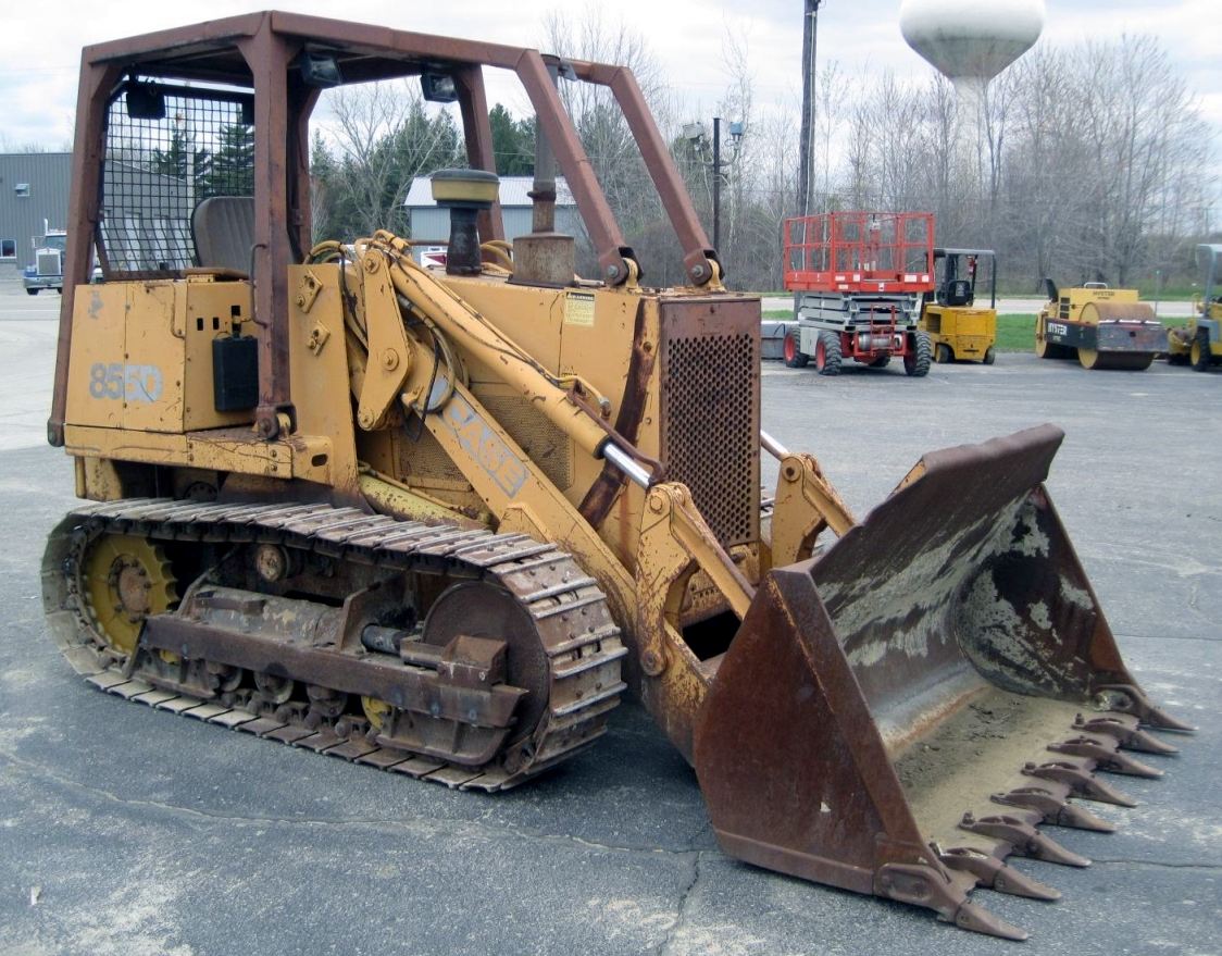
MAKE: Case
MODEL: 850D, 855D Crawler
FORMAT: PDF (1,422 pages)

Complete digital official shop manual contains service, maintenance, and troubleshooting information for the Case 850D, 855D Crawler. Diagnostic and repair procedures are covered in great detail to repair, maintain, rebuild, refurbish or restore your 850D, 855D like a professional mechanic in local service/repair workshop. This cost-effective quality manual is 100% complete and intact as should be without any missing pages. It is the same factory shop manual used by dealers that guaranteed to be fully functional to save your precious time.

This manual for Case 850D, 855D Crawler is divided into different sections. Each section covers a specific component or system and, in addition to the standard service procedures, includes disassembling, inspecting, and assembling instructions. A table of contents is placed at the beginning of each section. Pages are easily found by category, and each page is expandable for great detail. It is in the cross-platform PDF document format so that it works like a charm on all kinds of devices. You do not need to be skilled with a computer to use the manual.

EXCERPT:
Table of Contents
1 GENERAL
Safety Rules, Service Manual Introduction, and Torque Specifications … 1001
Maintenance and Lubrication .. 1 002
General Engine Specifications … 1010
Detailed Engine Specifications .. 1 024
2 ENGINES
Engine and Radiator Removal and Installation … 2000
Engine Accessories (Air Cleaner, Ether Injection System,
Muffler, Turbocharger, and Torque Converter) .. 2001
Engine Stall Tests .. 2002
Cylinder Head and Valve Train .. 2415
Cylinder Block, Pistons, Rods, Camshaft, Main Bearings,
Oil Seals, Flywheel and Crankshaft … 2425
Lubrication System … 2445
Cooling System .. 2455
Turbocharger .. 2465
Turbocharger Failure Analysis … 2565
3 FUEL SYSTEM
Fuel Lines, Fuel Tank, and Engine Controls … 3001
Fuel System and Filters … 3410
Bosch Fuel Injection Pump, Drive Gear, and Timing .. 3412
Fuel Filters .. 3413
4 ELECTRICAL
Removal and Installation of Electrical Components .. 4001
Electrical System Specifications and Troubleshooting .. : .. 4002
Wiring Diagrams … 4003
Gauges … 4004
Batteries … 4005
Starter and Starter Solenoid … 4006
Delco-Remy Alternator … 4007
45 Amp Alternator A186124 … 4008
45 Amp Alternator A 187916 … 4009
5 TRACK
Inspection of Track System Components … 5501
Case Lubricated Track … 5504
Standard Track and Track Frame .. 5506
Idler, Track Adjuster, and Recoil Housing … 5508
Sprocket … 5509
Carrier Roller .. 5510
Track Rollers .. , … 5511
CASE CORPORATION Bur 8-16520
6 POWER TRAIN
Transmission/Torque Converter Diagram and Troubleshooting … 6002
Charging Pump .. 6005
Transmission Control Valve … 6007
Modulator Valve … 6008
Removal and Installation of Torque Converter .. 6009
Torque Converter … 6010
Transmission … -… 6016
Final Drive .. 6017
Transmission Controls … 6018
Drive Shaft .. 6021
7 BRAKES
Brake Pedals, Removal and Installation of Master Cylinder, Adjustment and
Removing Air From Brake System … 7001
Master Cylinder .. 7002
Brake .. 7003
8 HYDRAULICS
Hydraulic Diagrams, Troubleshooting and Pressure Checks … 8002
Cleaning the Hydraulic System .. 8003
Rexroth Hydraulic Pump .. 8005
Vickers Hydraulic Pump … 8006
Equipment Control Valve … 8007
Cylinders … 8090
Backhoe Control Valve … 8107
Removal and Installation of Stabilizer Control Valve … 81 08
Stabilizer Control Valve .. 8109
9 MOUNTED EQUIPMENT
Air Conditioning Troubleshooting .. 9002
Air Conditioning System … 9003
Loader .. 9010
Blade on Dozer Models … 9020
Ripper … 9031
ROPS Cab and Canopy … 9061
Operators Seat and Seat Belt .. 9064
Suspension Seat .. 9065
Backhoe … 91 00
Winch .. 9300
Wiring Diagram … 850481
Hydraulic Schematic for Dozer … 850609
Hydraulic Schematic for Loader … 850610

Disassembly
1. Remove all dirt and grease from the idler.
2. Fasten acceptable lifting equipment to the idler so the idler will be in a horizontal position. The roll pin end of the shaft must be on top.
3. Remove the cap screw from the bottom bracket.
4. Remove the cap screw and lock plate from the top bracket. Drain the oil from the idler.
5. Remove the roll pin from the shaft.
6. Loosen the nut on the shaft.
7. Use the lifting equipment and put the idler in a press for removal of the shaft.
8. Remove the nut from the shaft.
9. Remove the bracket.
NOTE: If the metal rings of the face sea/ can be used again, do not mix the metal rings.
10. Remove the rubber ring.
11. Remove the metal rings.
12. Remove the other rubber ring.
13. Use an acceptable driver and press the shaft out of the idler. Do not let the shaft fall.
14. Put the idler in the press for removal of the bearing and adapter.
15. Use an acceptable driver and press the bearing and adapter out of the idler.
16. If necessary remove the bearing cups from the idler wheel.
a. Put the idler wheel on blocks that will support the hub of the idler wheel.
b. Install a puller as shown in the bottom
bearing cup and from the bottom of the idler wheel.
c. Put an acceptable driver on top of the puller and press the bearing cup out of the idler wheel.
d. Put the idler wheel in the press for removal of the other bearing cup.
e. Install an acceptable driver on top of the bearing cup.
f. Press the bearing cup out of the idler wheel.
17. Remove the spacer from the shaft.

Posted on

Case 845, 865, 885 Grader Workshop Repair & Service Manual


Download Link

INSTANT DOWNLOAD (add to cart)


865 total pages, bookmarked, Searchable, Printable, high quality PDF
6-46503 – 845, 865, 885 Grader Service Manual.pdf

Complete digital official shop manual contains service, maintenance, and troubleshooting information for the Case 845, 865, 885 Grader. Diagnostic and repair procedures are covered in great detail to repair, maintain, rebuild, refurbish or restore your Case 845, 865, 885 Grader like a professional mechanic in local service/repair workshop. This cost-effective quality manual is 100% complete and intact as should be without any missing pages. It is the same factory shop manual used by dealers that guaranteed to be fully functional to save your precious time.

This manual for Case 845, 865, 885 Grader is divided into different sections. Each section covers a specific component or system and, in addition to the standard service procedures, includes disassembling, inspecting, and assembling instructions. A table of contents is placed at the beginning of each section. Pages are easily found by category, and each page is expandable for great detail. It is in the cross-platform PDF document format so that it works like a charm on all kinds of devices. You do not need to be skilled with a computer to use the manual.

EXCERPT:
845 – 865 – 885 GRADER
Service Manual
Brz 6-46503
Table of Contents
General Tab 1
Section Index – General 6-46521
Special Tools – Cross Reference Guide 1000 6-15050
Standard Torque Specifications 1001 6-46530
Fluids and Lubricants 1002 6-46541
Metric Conversion Chart 1003 6-46550
Service Tools 1005 6-75330
Loctite Product Chart 8-98902
Engine Tab 2
Section Index – Engines 6-46561
For Engine Repair, See the Engine Service Manual
Charge Air Cooler 2002 6-75420
Fuel System Tab 3
Section Index – Fuel System 6-46591
For Fuel System Repair, See the Engine Service Manual
Electrical Tab 4
Section Index – Electrical 6-46601
Removal and Installation of Starter and Alternator 4001 6-42322
Electrical Diagram 4002 6-46621
Battery 4003 6-42331
Alternator 45 Ampere 4008 6-42361
Steering Tab 5
Section Index – Steering 6-46661
Front Wheel, Axle and Wheel Lean 5002 6-46681
Steering Control Valve (845 – 865 – 885 Grader) 5003 6-46691
Steering Priority Valve (845 – 865 – 885 Grader) 5004 6-46701
Power Train Tab 6
Section Index – Power Train 6-46731
Transmission Specifications, Pressure Checks and Troubleshooting (845 – 865 Grader) 6002 6-46751
Transmission Specifications, Pressure Checks and Troubleshooting (885 Grader) 6002 6-75350
Transmission (845 – 865 Grader) 6003 6-46761
Transmission (885 Grader) 6003 6-75360
Rear Axle With Differential Lock 6005 6-75370
Limited Slip Rear Axle 845-865 Grader 6005 6-46782
Tandem Drive Limited Slip Rear Axle 845-865 Grader 6006 6-46792
Tandem Drive Differential Hydraulic Lock 6006 6-75380
Brakes Tab 7
Section Index – Brakes 6-46810
Hydraulic Brake Troubleshooting 7002 6-46831
Brake Pedal Valve System 7003 6-46842
Hydraulics Tab 8
Section Index – Hydraulics 6-46861
Removal and Installation of Hydraulic Components 8001 6-46872
Hydraulic Schematics 8002 6-75400
Mounted Equipment Tab 9
Section Index – Mounted Equipment 6-46931
Air Conditioning Troubleshooting 9002 6-46950
Air Conditioning Troubleshooting For Systems With
HFC 134A Refrigerant 9002 6-75390
Air Conditioner System Operating Instructions 9003 6-46960
Air Conditioner System Service 9003 6-42650
Removal and Installation of Air Conditioning Components for Systems with
HFC 134A Refrigerant 9004 6-46971
Rear Ripper 9007 6-47011
Frame, Articulation Joint, Circle and Scarifier 9008 6-47001
Front Blade and Counterweight 9009 6-47021
ROPS Cab 9010 6-47031
Cab Glass Installation 9011 6-47041

Section Drawing and Integral Valves
NOTE: The steering control valve housing (7) Fig. 2 has internally two anti-cavitation valves (EE) and one check valve (CC). Before removing these valves, verify their positions.
17. To disassemble these valves, insert soda straws (3) in each end of the threaded holes, refer to Figure 3. Remove the steering control valve housing from the vise and tilt it until the port face (4) is upward. Continue turning until the roll pins (2) and ball checks (1) slide through the straws (3).
FIGURE 8. ANTI-CAVITATION VALVE – DISASSEMBLY
1. BALL CHECK 2. ROLL PIN 3. SODA STRAW 4. PORT FACE 5. ANTI-CAVITATION VALVES 6. CHECK VALVE
Inspection
1. Clean all parts in cleaning solvent and air dry on paper towels. Do not use cloths to wipe parts dry, as it may leave lint on the parts.
2. Check all machined surfaces for wear or damage. If there are rough places on the ends of the gerotor star or gerotor (4), steering control valve housing (7), end cap (2), or spacer plate (5), use 600 grit emery cloth to smooth the surfaces, refer to Figure 2. Place the emery cloth on a flat surface. If the emery cloth is new, rub a piece of steel across the emery cloth six times to remove the sharp pieces of grit. Make sure that the part is held flat on the emery cloth. Rub each part across the cloth six times. Check to see if the rough places are removed. Use this method until all rough places are removed. Clean the parts in cleaning solvent to remove any grit.
3. If the spool (9) and sleeve (8) or the bore in the housing of the steering control valve (7) is damaged or worn, use a new steering control valve.
4. Inspect the cap screws (1), pin (11), backup washer (15), seal ring (16), O-ring (17), needle thrust bearing (13) and bearing race (14). Use new parts as required.
5. If your steering control valve has anti-cavitation and check valves, inspect the balls checks (20), (23) and roll pins(21), (22) for damage or wear. Use new parts as required.

Posted on

Case Wheel Loader 821G, 921G Factory Service & Shop Manual


Download Link

INSTANT DOWNLOAD (add to cart)


total 2,707 pages, bookmarked, Searchable, Printable, high quality PDF
48082199 – Wheel Loader 821G, 921G Stage IV Service Manual.pdf; 2,707 pages
SERVICE MANUAL
821G WHEEL LOADER XR-EH, NEW CAB TIER4B
821G WHEEL LOADER ZBAR-EH, NEW CAB TIER4B
921G WHEEL LOADER XR-EH, NEW CAB TIER4B
921G WHEEL LOADER ZBAR-EH, NEW CAB TIER4B

Complete workshop & service manual with electrical wiring diagrams for Case Wheel Loader 821G, 921G. It’s the same service manual used by dealers that guaranteed to be fully functional and intact without any missing page.

This Case Wheel Loader 821G, 921G service & repair manual (including maintenance, overhaul, disassembling & assembling, adjustment, tune-up, operation, inspecting, diagnostic & troubleshooting…) is divided into different sections. Each section covers a specific component or system with detailed illustrations. A table of contents is placed at the beginning of each section. Pages are easily found by category, and each page is expandable for great detail. The printer-ready PDF documents work like a charm on all kinds of devices.

EXCERPT:
Contents
INTRODUCTION
Engine.. 10
[10.001] Engine and crankcase . . 10.1
[10.202] Air cleaners and lines . . 10.2
[10.500] Selective Catalytic Reduction (SCR) exhaust treatment . . 10.3
[10.400] Engine cooling system . . 10.4
[10.414] Fan and drive . . 10.5
[10.310] Aftercooler. . 10.6
[10.304] Engine lubrication system . . 10.7
Transmission.. 21
[21.113] Powershift transmission . . 21.1
[21.155] Powershift transmission internal components. . 21.2
[21.700] Torque converter . . 21.3
Four-Wheel Drive (4WD) system .. 23
[23.314] Drive shaft. . 23.1
Front axle system .. 25
[25.100] Powered front axle . . 25.1
[25.102] Front bevel gear set and differential . . 25.2
[25.108] Final drive hub, steering knuckles, and shafts . . 25.3
Rear axle system.. 27
[27.100] Powered rear axle. . 27.1
[27.106] Rear bevel gear set and differential . . 27.2
[27.120] Planetary and final drives . . 27.3
Brakes and controls .. 33
[33.202] Hydraulic service brakes . . 33.1
[33.110] Parking brake or parking lock . . 33.2
Hydraulic systems.. 35
[35.000] Hydraulic systems. . 35.1
[35.300] Reservoir, cooler, and filters. . 35.2
[35.106] Variable displacement pump . . 35.3
[35.359] Main control valve . . 35.4
[35.357] Pilot system . . 35.5
[35.752] Hydraulic fan drive cooling system. . 35.6
[35.701] Front loader arm hydraulic system . . 35.7
[35.723] Front loader bucket hydraulic system . . 35.8
[35.734] Tool quick coupler hydraulic system . . 35.9
Frames and ballasting .. 39
[39.100] Frame . . 39.1
Steering.. 41
[41.101] Steering control . . 41.1
[41.200] Hydraulic control components. . 41.2
[41.216] Cylinders . . 41.3
[41.910] Auxiliary steering . . 41.4
Wheels.. 44
[44.511] Front wheels. . 44.1
[44.520] Rear wheels . . 44.2
Cab climate control .. 50
[50.200] Air conditioning. . 50.1
Electrical systems .. 55
[55.100] Harnesses and connectors. . 55.1
[55.301] Alternator. . 55.2
[55.302] Battery. . 55.3
[55.988] Selective Catalytic Reduction (SCR) electrical system . . 55.4
[55.989] Exhaust Gas Recirculation (EGR) electrical system . . 55.5
[55.512] Cab controls. . 55.6
[55.530] Camera. . 55.7
[55.DTC] FAULT CODES. . 55.8
Front loader and bucket.. 82
[82.100] Arm. . 82.1
[82.300] Bucket . . 82.2
Platform, cab, bodywork, and decals .. 90
[90.150] Cab. . 90.1
[90.105] Machine shields and guards . . 90.2
..
Rear axle system – Planetary and final drives
Wheel hub – Visual inspection – Models MT-L 3085 II / MT-L 3095 II
1. Clean all parts except the friction plates in the brake disc pack by using cleaning solvent. Use compressed air to clear the passages in the planetary ring gear and brake housing.
NOTICE: wear face protection when using compresses air.
2. Inspect the bearing rollers for pitting, scoring, deformation, or other damage. Check the inner face and bearing cage for deformation, dents, and other damage.
Check the associated bearing cups for scratches, grooves, or cracks. Check the bearings for rough spots or binding by holding bearing and rotating. If the bearing binds or action is not smooth, replace the bearing.
3. Inspect the bearing cups for pitting, scoring, cracks, or other damage. Replace if any of these conditions are seen.
NOTE: if a bearing or bearing cup requires replacement, the associated part must also be replaced.
4. Check the planetary ring gear, planetary gears, and planetary carrier gear teeth for cracks, breaks, chipping, or other damage. Replace the part if any of these conditions are seen. Check the planetary carrier shaft splines for broken, cracked, or twisted condition. Replace if needed.
5. Check the wheel end shaft for cracked, broken, or twisted splines. Replace if any of these conditions are seen.
..

Posted on

Case 821F, 921F Wheel Loader Workshop Repair & Service Manual


Download Link

INSTANT DOWNLOAD (add to cart)


total 3,600 + pages, bookmarked, Searchable, Printable, high quality PDF
47673352 – 821F, 921F Tier 4B (final) Wheel Loader Service Manual.pdf – 2,304 pages
47680550 – 821F, 921F Tier 4B (final) Wheel Loader Service Manual (10 Engine, 21 Transmission).pdf – 339 pages
84419918 – 821F, 921F Wheel Loader Hydraulic Schematic.pdf – 886 pages
84487565 – 821F, 921F Tier 4 Wheel Loader Service Manual.pdf – 1,063 pages
84548506 (Replaces 84324413) – 821F, 921F Tier 4 Wheel Loader Operator’s Manual.pdf – 304 pages

Complete digital official shop manual contains service, maintenance, and troubleshooting information for the Case 821F, 921F Wheel Loader. Diagnostic and repair procedures are covered in great detail to repair, maintain, rebuild, refurbish or restore your Case 821F, 921F Wheel Loader like a professional mechanic in local service/repair workshop. This cost-effective quality manual is 100% complete and intact as should be without any missing pages. It is the same factory shop manual used by dealers that guaranteed to be fully functional to save your precious time.

This manual for Case 821F, 921F Wheel Loader is divided into different sections. Each section covers a specific component or system and, in addition to the standard service procedures, includes disassembling, inspecting, and assembling instructions. A table of contents is placed at the beginning of each section. Pages are easily found by category, and each page is expandable for great detail. It is in the cross-platform PDF document format so that it works like a charm on all kinds of devices. You do not need to be skilled with a computer to use the manual.

EXCERPT:
OPERATION
The refrigerant circuit of the air conditioning system contains five major components: compressor, condenser, receiver-drier, expansion valve and evaporator. These components are connected by tubes and hoses and operate as a closed system.
The air conditioner system is charged with HFC-134a refrigerant.
The compressor receives the refrigerant as a low pressure gas. The compressor then compresses the refrigerant and sends it in the form of a high pressure gas to the condenser. The air flow through the condenser then removes the heat f rom the refrigerant. As the heat is removed the refrigerant changes to a high pressure liquid.
The high pressure refrigerant liquid then flows from the condenser to the receiver-drier. The receiver-drier is a container filled with moisture removing material, which removes any moisture that may have entered the air conditioner system in order to prevent corrosion of the internal components of the air conditioner system.
The refrigerant, still in a high pressure liquid form, then flows from the receiver-drier to the expansion valve. The expansion valve then causes a restriction in flow of refrigerant to the evaporator core. The evaporator meters refrigerant flow based on evaporator heat load.
As the refrigerant flows through the evaporator core, the refrigerant is heated by the air around and flowing through the evaporator fins. The combination of increased heat and decreased pressure causes the air flow through the evaporator fins to become very cool and the liquid refrigerant to become a low pressure gas. The cooled air then passes from the evaporator to the cab for the operator’s comfort.
The electrical circuit of the air conditioning system consists of a fan speed control, temperature control, one (1) relay, a blower motor, blower resistor, A.C. compressor clutch, A.C. low pressure switch, A.C. high pressure switch, and A.C. warning light.
1. EXPANSION VALVE 2. EVAPORATOR 3. COMPRESSOR 4. CONDENSER 5. RECEIVER-DRIER
TROUBLESHOOTING
Perform a visual inspection of the machine. Check the following and correct as necessary:
1. – Obtain service history if possible.
2. – Is compressor drive belt in place and tensioned?
3. – Are grille screens, fan blades, condenser, air filter, and evaporator unobstructed?
4. – Are there any sharp bends or kinks in the hoses?
5. – Are there heavy accumulations of oil, or oily dust around the fittings, indicating refrigerant
leakage?
6. – Are air ducts undamaged, sealed properly and in position?
7. – Condensate drain hoses and check valves present and unobstructed?
Problem: No Cooling

Posted on

Case 821E Wheel Loader Workshop Repair & Service Manual


Download Link

INSTANT DOWNLOAD (add to cart)


total 1,000+ pages, bookmarked, Searchable, Printable, high quality PDF
84299244 (Replaces 87364100) – 821E Tier 3 Wheel Loader Service Manual.pdf – 855 pages
87479861 NA (Replaces 87364251 NA) – 721E, 821E Tier 3 Operator’s Manual.pdf – 268 pages
5-3310 – Electrical Schematic 821E Wheel Loader.pdf

Complete digital official shop manual contains service, maintenance, and troubleshooting information for the Case 821E Wheel Loader. Diagnostic and repair procedures are covered in great detail to repair, maintain, rebuild, refurbish or restore your Case 821E Wheel Loader like a professional mechanic in local service/repair workshop. This cost-effective quality manual is 100% complete and intact as should be without any missing pages. It is the same factory shop manual used by dealers that guaranteed to be fully functional to save your precious time.

This manual for Case 821E Wheel Loader is divided into different sections. Each section covers a specific component or system and, in addition to the standard service procedures, includes disassembling, inspecting, and assembling instructions. A table of contents is placed at the beginning of each section. Pages are easily found by category, and each page is expandable for great detail. It is in the cross-platform PDF document format so that it works like a charm on all kinds of devices. You do not need to be skilled with a computer to use the manual.

EXCERPT:
Table of Contents
General
Section Index- General
Standard Torque Specifications
Fluids and Lubricants
Metric Conversion Chart
Engines
Section Index- Engines
Description
Engine and Radiator Removal and Installation
Stall Tests
After Cooler
For Engine Repair, See the Engine Service Manual
Fuel System
Section Index- Fuel System
For Fuel System Repair, See the Engine Service Manual
Electrical
Section Index- Electrical
Removal and Installation of Starter and Alternator
Electrical Specifications and Troubleshooting
Batteries
Instrument Cluster
Steering
Section Index- Steering
Removal and Installation of Steering Components
Steering Specifications, Pressure Checks, and Troubleshooting
Steering Cylinders
Center Pivot
Auxiliary Steering Motor and Pump
Joystick Steering
Power Train
Section Index- Power Train
Removal and Installation of Power Train Components
Transmission Specifications, Pressure Checks, and Troubleshooting
Transmission
Front Axle
Rear Axle
Drive Shafts, Center Bearing, and Universal Joints
Wheels and Tires
Transmission Control Valve
Brakes
Section Index – Brakes
Removal and Installation of Brake Components
Hydraulic Brake Troubleshooting
Brake Pump
Brake Accumulators
Parking Brake
Hydraulics
Section Index- Hydraulics
Removal and Installation of Hydraulic Components
Hydraulic Specifications, Troubleshooting, and Pressure Checks
Cleaning the Hydraulic System
Hydraulic Pump
Loader Control Valve
Cylinders
Coupler Solenoid Locking Valve
Ride Control Accumulator
Ride Control Valve
Mounted Equipment
Section Index- Mounted Equipment
Air Conditioning Troubleshooting and System Checks For Systems with HFC-134a
Refrigerant
Air Conditioner System Service
Removal and Installation of Air Conditioning and Heater Components Loader
Rollover Protective Structure (ROPS) Cab Structural Frame (CSF)
Cab Glass Installation
Electrical Schematic Foldouts and Hydraulic Schematic Foldout

Transmission Clutch Calibration
The Transmission ECM has the capability to find the optimal adjustment of the clutch filling parameters for each individual transmission, providing the ability to individually adjust the optimum fill time for the individual transmission in the machine. Clutch Filling Parameter Calibration is performed on each machine at the plant and should be repeated at the first 250 hours of use and every 1000 hours thereafter.
Before doing the following transmission clutch calibration procedures make sure of the following:
1. The machine is running and the transmission oil is warm.
2. Engine low idle speed is correct.
3. The transmission is in neutral.
4. The park brake is applied.
5. If steps 1 through 4 have been accomplished, calibrate the transmission clutches as follows:
A. Press and hold the enter key for 2 to 3 seconds and the monitor will change to SELECT.
B. Use the down arrow and high light “CONFIG”, press the enter key.
C. Press the down arrow and high light “CALIB G/B”, press the enter key.
D. Monitor will state “CALIB G/B” “CONFIRM PLEASE”, press the enter key.
E. If the conditions are not correct for clutch calibration the monitor will display the problem that needs to be corrected.
F. Clutch calibration status will be displayed on the monitor, “ADJUST K1, K2, K3, K4, KV, KR”.
G.After completing the Clutch Calibration procedure, turn the machine OFF for 15 seconds. This sets the calibration in the controller.
Gear Selections
The transmission provides 4 forward and 3 reverse gear selections. The transmission ratios were designed to give optimized speed and torque for each gear selection. The torque converter is a single stage torque converter (one locking unit in the torque converter).
Automatic/Manual Modes
The automatic/manual switch is located on the right control panel. The transmission is in automatic mode when the top of the automatic/manual switch is depressed. The Transmission Display Center indicates when the machine is in the automatic mode.
Upshifting in Automatic Mode
Upshifting is determined by machine speed and the torque on the transmission.
The transmission will shift from first or second gear up to the highest gear selected as the accelerator is depressed, machine speed increases, and required torque is reduced.
If the machine speed is increasing, but the operator
is not depressing the accelerator (such as when going down a hill), the transmission will not upshift.
As the operator depresses the accelerator and the torque on the transmission is lowered, the transmission will upshift.
Downshifting in Automatic Mode
Downshifting is determined directly by machine speed and transmission torque. The transmission will downshift to first or second gear as machine speed decreases and transmission torque increases. For example, if the unit begins to climb a hill in forth gear and the machine speed decreases, as the torque requirement increases, the transmission will downshift into third, then second, and down to first gear, if necessary.
Upshifting in Manual Mode
In the manual mode, the transmission starts out in the selected gear and stays in that gear until the operator selects another gear or direction. The transmission can be upshifted without reducing engine speed or machine speed.
If the gear selected is two or more gears higher than the present gear, the transmission will shift up through the gears at 2.5 second intervals until the selected gear has been reached.