Posted on

Case CX160 Crawler Excavator Factory Service & Shop Manual


Download Link

INSTANT DOWNLOAD (add to cart)


1,902 total pages, bookmarked, Searchable, Printable, high quality PDF
7-28381 – Pelles sur Chenilles CX160 MANUEL DE SERVICE (FR).pdf
7-29061 – CX160 Crawler Excavators Service Manual (EN).pdf
7-29071 – CX160 RAUPENBAGGER REPARATUR HANDBUCH (DE).pdf

Complete workshop & service manual with electrical wiring diagrams for Case CX160 Crawler Excavator. It’s the same service manual used by dealers that guaranteed to be fully functional and intact without any missing page.

This Case CX160 Crawler Excavator service & repair manual (including maintenance, overhaul, disassembling & assembling, adjustment, tune-up, operation, inspecting, diagnostic & troubleshooting…) is divided into different sections. Each section covers a specific component or system with detailed illustrations. A table of contents is placed at the beginning of each section. Pages are easily found by category, and each page is expandable for great detail. The printer-ready PDF documents work like a charm on all kinds of devices.

EXCERPT:
Apply clean grease on the O-ring (5) if this has not already been done and install the O-ring on the shaft (6). Install the hub (4) on the shaft and install a new
snap ring (3) to fasten the hub and shaft. Install a drain plug (1).
NOTE: Check the pitch of the retaining ports of the tension shock absorber yoke, see page 8.
STEP 7
Check for leaks to ensure that the idler wheel has been correctly reassembled and check for any damage which could give rise to leaks at seals and other components

Posted on

Case CX135SR Crawler Excavator Factory Service & Shop Manual


Download Link

INSTANT DOWNLOAD (add to cart)


2,824 total pages, bookmarked, Searchable, Printable, high quality PDF
9-40470 – EXCAVADORA SOBRE ORUGAS CX135SR SCHEMATIC SET (ES).pdf
9-40480 – ESCAVATORE CINGOLATO CX135SR SCHEMATIC SET (IT).pdf
9-40631 – Pelles sur Chenilles CX135SR MANUEL DE SERVICE (FR).pdf
9-40641 – CX135SR Crawler Excavator Repair Manual (EN).pdf
9-40671 – CX135SR Raupenbagger REPARATUR HANDBUCH (DE).pdf

Complete workshop & service manual with electrical wiring diagrams for Case CX135SR Crawler Excavator. It’s the same service manual used by dealers that guaranteed to be fully functional and intact without any missing page.

This Case CX135SR Crawler Excavator service & repair manual (including maintenance, overhaul, disassembling & assembling, adjustment, tune-up, operation, inspecting, diagnostic & troubleshooting…) is divided into different sections. Each section covers a specific component or system with detailed illustrations. A table of contents is placed at the beginning of each section. Pages are easily found by category, and each page is expandable for great detail. The printer-ready PDF documents work like a charm on all kinds of devices.

EXCERPT:
Track tensioning mechanism Adjuster-recoil mechanism – Install (D.50.B.48.65 – F.10.A.15)
Check that the cylinder rod is inserted as far as possible into the cylinder barrel.
Move the tension cylinder into position.
Apply thread lock uid to the screws.
Support the tension cylinder whilst an assistant installs theat washers and screws to secure it.
Tighten the screws.
Next operation: Install the roller located under the tension cylinder, refer to Roller Lower roller – Install

Next operation: Steel track – Install (D.50.B.46 – F.10.A.15

Posted on

Case CX130 Crawler Excavator Factory Service & Shop Manual


Download Link

INSTANT DOWNLOAD (add to cart)


4,074 total pages, bookmarked, Searchable, Printable, high quality PDF
7-27343 – Pelles sur Chenilles CX130 MANUEL DE SERVICE (FR).pdf
7-27353 – CX130 Crawler Excavators Service Manual (EN).pdf
7-27363 – CX130 RAUPENBAGGER REPARATUR HANDBUCH (DE).pdf

Complete workshop & service manual with electrical wiring diagrams for Case CX130 Crawler Excavator. It’s the same service manual used by dealers that guaranteed to be fully functional and intact without any missing page.

This Case CX130 Crawler Excavator service & repair manual (including maintenance, overhaul, disassembling & assembling, adjustment, tune-up, operation, inspecting, diagnostic & troubleshooting…) is divided into different sections. Each section covers a specific component or system with detailed illustrations. A table of contents is placed at the beginning of each section. Pages are easily found by category, and each page is expandable for great detail. The printer-ready PDF documents work like a charm on all kinds of devices.

EXCERPT:
NOTE: Carry out this step only if inspection reveals that the bushings (8) need to be replaced.
Using a hammer and a brass punch, drive the bushings (8) from the lower roller (1). Be careful not to damage the seal bore in the lower roller. Discard bushings.
If removed, install new bushings (8) in the lower roller (1) using a hydraulic press and a proper size rod.
STEP 1
Inspection
STEP 2
Clean all components with solvent.
STEP 3
Inspect the bushing surfaces on the shaft (6) for scoring, pitting, and other damage. Measure the diameter of the shaft at four opposing points.
Compare the values with the specifications, replace them if necessary.
STEP 4
Install an O-ring and a face seal metal bushing (5) in the seal bore on each side of the lower roller.
Inspect bushings (8) for wear and damage. Measure the inner diameter and width of the bushing.
Compare the values with the specifications, replace them if necessary.
STEP 5
Inspect the bore in each end cap and in the lower roller for damage that will result in leakage. Use new parts as required.

Posted on

Case CX130B Crawler Excavator Factory Service & Shop Manual


Download Link

INSTANT DOWNLOAD (add to cart)


Complete workshop & service manual with electrical wiring diagrams for Case CX130B Crawler Excavator. It’s the same service manual used by dealers that guaranteed to be fully functional and intact without any missing page.

This Case CX130B Crawler Excavator service & repair manual (including maintenance, overhaul, disassembling & assembling, adjustment, tune-up, operation, inspecting, diagnostic & troubleshooting…) is divided into different sections. Each section covers a specific component or system with detailed illustrations. A table of contents is placed at the beginning of each section. Pages are easily found by category, and each page is expandable for great detail. The printer-ready PDF documents work like a charm on all kinds of devices.

2,973 total pages, bookmarked, Searchable, Printable, high quality PDF
“84139197B NA – CX130B / CX130B Blade Tier 3 Service Manual.pdf”
“87594014B – CX130B, CX160B Electrical Schematic.pdf”
“87725726A – CX130B Hydraulic Schematic.pdf”
“87594000B – CX130B, CX160B, CX180B Excavator Electrical Schematic.pdf”
“87725711A – CX130B Excavator Hydraulic Schematic.pdf”
“KNJ15290-E01-EN – CX130B 2PC Excavator Hydraulic Schematic.pdf”
“SM130BTOC-1EN – Crawler Excavator CX130B Service Manual.pdf”

EXCERPT:
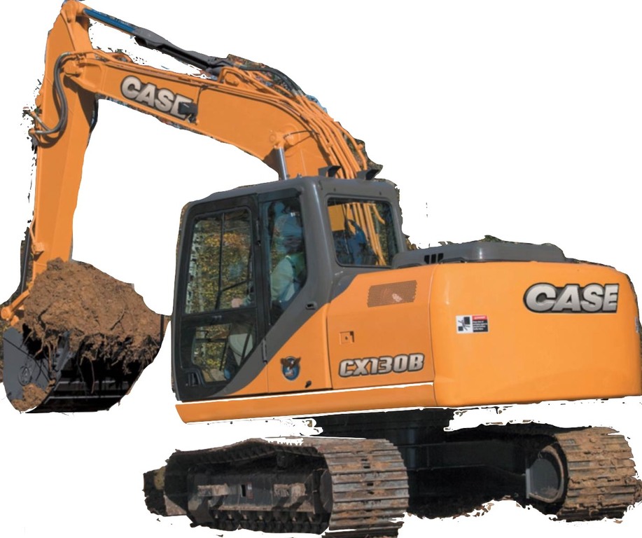
CRAWLER EXCAVATOR CX130B
SERVICE MANUAL
TABLE OF CONTENTS
DIVISION/SECTION SECTION N° REFERENCE N°
1 GENERAL INFORMATION
Safety, general information and standard torque data…. 1001 7-27691NA
General specifications and special torque setting …. 1002 SC130B1002-1NA
2 ENGINE
Removal and installation of the engine… 2000 SM130B2000-0EN
Removal and installation of the fuel cooler, engine inter-cooler,
radiator and oil cooler…. 2001 SM130B2001-0EN
Removal and installation of the turbo charger … 2004 SM130B2004-0EN
Removal and installation of EGR cooler and EGR valve… 2005 SM130B2005-0EN
Removal and installation of the engine hood… 2006 SM130B2006-0EN
Engine specifications…*
Disassembly and assembly of the engine …*
3 FUEL SYSTEM
Removal and installation of the fuel tank… 3001 SM130B3001-0EN
Removal and installation of the supply pump and common rail … 3004 SM130B3004-0EN
Removal and installation of the injectors … 3005 SM130B3005-0EN
Fuel engine system ….*
4 ELECTRICAL SYSTEM
Electrical and engine functions and service support …. 4001 SC130B4001-0NA
Removal and installation of the starter motor …. 4004 SM130B4004-0EN
Removal and installation of the alternator … 4005 SM130B4005-0EN
Electrical equipment and electrical circuit diagrams… 4020 SC210B4020-1NA
Engine error code (DTC) … 4021 SM130B4021-0EN
Main body error code (DTC)…. 4022 SM130B4022-0EN
Troubleshooting, 4JJ1 engine…. 4023 SM130B4023-0EN
5 UNDERCARRIAGE
Removal and installation of tracks …. 5001 SM130B5001-0EN
Rollers …. 5003 SM130B5003-0EN
Take-up roller… 5005 SM130B5005-0EN
6 DRIVE TRAIN
Removal and installation of the drive motor and
final drive transmission…. 6001 SM130B6001-0EN
Disassembly and assembly of the drive motor and
final drive transmission…. 6002 SM130B6002-0EN
Removal and installation of the swing motor and
swing reduction gear … 6003 SM130B6003-0EN
Disassembly and assembly of the swing reduction gear … 6004 SM130B6004-0EN
7 UNDERCARRIAGE HYDRAULICS
8 UPPERSTRUCTURE HYDRAULICS
Depressurising and decontaminating the hydraulic system, use of the
vacuum pump and bleeding the components…8000 SM160B8000-0NA
Specifications, troubleshooting, checks and
hydraulic pressure settings….8001 SC130B8001-0NA
Removal and installation of the hydraulic reservoir ….8002 SM130B8002-0EN
Removal and installation of the main hydraulic pump…8003 SM130B8003-0EN
Removal and installation of the main hydraulic control valve…8004 SM130B8004-0EN
Removal and installation of the attachment cylinders…8005 SM130B8005-0EN
Removal and installation of the hydraulic swivel …8006 SM130B8006-0EN
Removal and installation of the pilot blocs…8007 SM130B8007-0EN
Disassembly and assembly of the main hydraulic pump …8010 SM130B8010-0EN
Disassembly and assembly of the main hydraulic control valve …8011 SM130B8011-0EN
Disassembly and assembly of the attachment cylinders …8012 SM130B8012-0EN
Disassembly and assembly of the hand control levers ….8013 SM130B8013-0EN
Disassembly and assembly of the foot control levers …8014 SM130B8014-0EN
Disassembly and assembly of the cushion valve….8016 SM130B8016-0EN
Removal and installation of the safety valve ….8017 SM130B8017-0EN
Disassembly and assembly of the swing motor ….8019 SM130B8019-0EN
Hydraulic functions …8020 SC130B8020-0NA
Hydraulic component functions…8030 SC130B8030-0NA
9 UPPERSTRUCTURE
Removal and installation of the counterweight ….9002 SM130B9002-0EN
Removal and installation of the boom, dipper and bucket …9003 SM130B9003-0EN
Removal and installation of the seat …9004 SM130B9004-0EN
Removal and installation of the cab and cab equipment …9005 SM130B9005-0EN
Air conditioner functions and troubleshooting….9006 SC210B9006-1NA
Air conditioning unit ….9007 SM130B9007-0EN
Air conditioning components….9009 SM130B9009-0EN
Large size hydraulic schematics …. Pocket 87725726A
Large size electrical schematics …. Pocket 87594014B