Posted on

Case W14/W14H/W14FL Articulated Loaders Workshop Repair & Service Manual


Download Link

INSTANT DOWNLOAD (add to cart)


2,810 pages, bookmarked, Searchable, Printable, high quality PDF
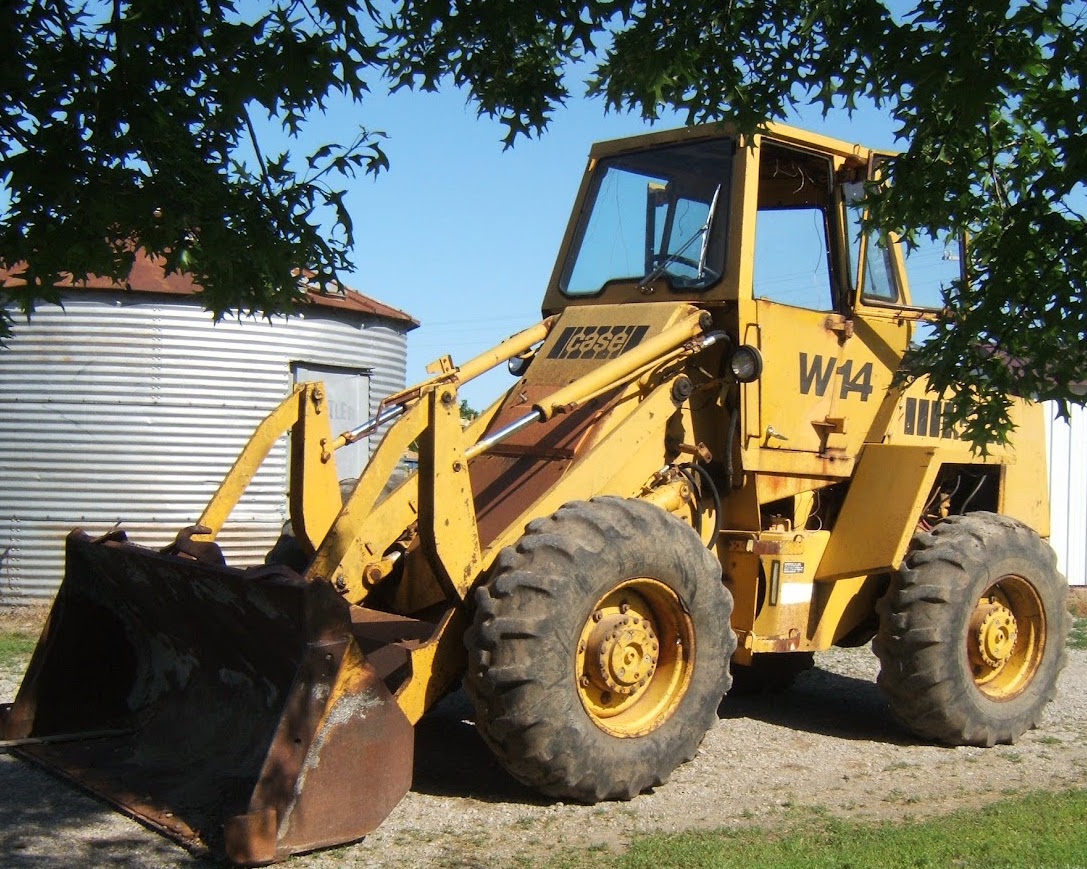
MAKE: Case
MODEL: W14, W14H, and W14FL Articulated Loaders

W14 (Prior 9119672) Service Manual; 813 pages
W14 (After 9119672) Service Manual; 1,639 pages
9-3212: W14 (SN: 9119395-9119672) Operator’s Manual; 104 pages
9-4195: W14 (SN: Prior to 9119395) Operator’s Manual; 104 pages
9-3324: W14 (SN: W14 (9119672 & After) Operator’s Manual; 150 pages

Complete digital official shop manual contains service, maintenance, and troubleshooting information for the Case W14/W14H/W14FL Articulated Loaders. Diagnostic and repair procedures are covered in great detail to repair, maintain, rebuild, refurbish or restore your Case W14/W14H/W14FL Articulated Loaders like a professional mechanic in local service/repair workshop. This cost-effective quality manual is 100% complete and intact as should be without any missing pages. It is the same factory shop manual used by dealers that guaranteed to be fully functional to save your precious time.

This manual for Case W14/W14H/W14FL Articulated Loaders is divided into different sections. Each section covers a specific component or system and, in addition to the standard service procedures, includes disassembling, inspecting, and assembling instructions. A table of contents is placed at the beginning of each section. Pages are easily found by category, and each page is expandable for great detail. It is in the cross-platform PDF document format so that it works like a charm on all kinds of devices. You do not need to be skilled with a computer to use the manual.

EXCERPT:
Test No.5- Voltage Loss in the Negative Battery Cable
1. Do Test No.1.
2. Select the volt range of 0 to 3 volte.
3. Connect the black voltmeter lead to the negative post of the left battery.
4. Connect the red voltmeter lead to a good engine ground.
5. Push in and hold the remote starter switch.
Read the voltmeter. Release the remote starter switch.
a. If the voltmeter indication was .4 or less, the negative battery cable is good.
b. If the voltmeter indication was more than .4 volt, replace the negative battery cable.
TROUBLESHOOTING THE AUTOMATIC AUXILIARY STEERING
Your machine can have one of two designs of the electronic circuits which control the automatic auxiliary steering. Look at the relay assembly below the instrument panel on the left side of the machine. Early machines have two large capacitors, component G on page 4002-21. Late machines have one large capacitor and one large resistor, components G and M on page 4002-30.
Early Machines
Auxiliary Steering Motor
Does Not Run
See illustration on page 4002-27.
1. Start and run the engine at 1500 rpm (r/min) for one minute.
2. Stop the engine while you keep the key switch in the Run position.
3. Use a voltmeter or a 24 volt test lamp to check for electrical system voltage at point 0.
a. If there was electrical system voltage at point 0, go to step 4.
b. If there was no voltage at point 0, the cable between the starter and the auxiliary steering motor is damaged. Check the connections and replace the cable if necessary.
4. Check for electrical system voltage at point P.
a. If there was no voltage at point P, go to step 5.
b. If there was voltage at point P, the magnetic switch on the auxiliary steering motor or the auxiliary steering motor is damaged. See section 5025 to check the magnetic switch and the auxiliary steering motor.
5. There is a black wire connected to the flow switch (C). Disconnect this black wire from the bullet connector (Q). Check for voltage at the bullet connector (Q).
a. If there was voltage at the bullet connector, go to step 7.
b. If there was no voltage at the bullet connector, go to step 6.
6. Check the 5 ampere circuit breaker on the instrument panel. If you can see the red band on the button for the circuit breaker, push the button. Release the button. If you can see the red band on the button again, there is a short circuit in the electrical circuit for the auxiliary steering. Check the following items.
a. Insulation on the wires in the circuit.
b. Check the wires for the capacitors (G). Make sure that the wires for the capacitors are not in contact with the sockets for the relays or in contact with the relay bracket.
c. The 5 ampere circuit breaker is damaged. Replace the 5 ampere circuit breaker.
d. If you have not found the problem, replace the capacitors (G) and the resistor (1).
7. Connect the black wire to the bullet connector. Disconnect the red wire for the flow switch from the red-white wire at the bullet connector. Check for voltage at the red wire.
a. If there was voltage at the red wire, go to step 8.
b. If there was no voltage at the red wire, the flow switch is damaged. Replace the flow
switch.
8. Check for voltage at point R.
a. If there was voltage at point R, go to step 9.
b. If there was no voltage at point R, the relay is bad. Replace the relay.
9. Check for voltage at pointS.
a. If there was voltage at pointS, go to step 10.
b. If there was no voltage at pointS, the resistor (H) is bad. Replace the resistor.
10. Check for voltage at point T.
a. If there was voltage at point T, go to step 11.
b. If there was no voltage at point T, the relay is bad. Replace the relay.
11. Check the white-black wire between the socket and the magnetic switch on the auxiliary steering motor. If there is voltage at point T and the auxiliary steering motor still will not run, the white-black wire is damaged and must be replaced.

INSTANT DOWNLOAD (add to cart)


Posted on

Case TX130-30, TX130-30 TURBO, TX130-33, TX130-33 TURBO Factory Service & Shop Manual


Download Link

INSTANT DOWNLOAD (add to cart)

Case TX130-30, TX130-30 TURBO, TX130-33, TX130-33 TURBO Factory Service & Shop Manual

2,475 pages, bookmarked, Searchable, Printable, high quality PDF

9_93200 – NOTICE DE RÉPARATION CHARIOTS ELEVATEURS TELESCOPIQUES TX130-30, TX130-30 TURBO, TX130-33, TX130-33 TURBO (FR).pdf
9_93210 – WORKSHOP MANUAL TELEHANDLERS TX130-30, TX130-30 TURBO, TX130-33, TX130-33 TURBO (EN).pdf
9_93220 – WERKSTATTHANDBUCH TELESKOP-LADER TX130-30, TX130-30 TURBO, TX130-33, TX130-33 TURBO (DE).pdf
9_93230 – MANUAL DE ISTRUCCIONES PARA LAS REPARACIONES TELEMANIPULADORES TX130-30, TX130-30 TURBO, TX130-33, TX130-33 TURBO (ES).pdf
9_93250 – MANUALE DELLE ISTRUZIONI PER LE RIPARAZIONI MOVIMENTATORI TELESCOPICI TX130-30, TX130-30 TURBO, TX130-33, TX130-33 TURBO (IT).pdf

Complete workshop & service manual with electrical wiring diagrams for Case TX130-30, TX130-30 TURBO, TX130-33, TX130-33 TURBO. It’s the same service manual used by dealers that guaranteed to be fully functional and intact without any missing page.

Case TX130-30, TX130-30 TURBO, TX130-33, TX130-33 TURBO service & repair manual (including maintenance, overhaul, disassembling & assembling, adjustment, tune-up, operation, inspecting, diagnostic & troubleshooting…) is divided into different sections. Each section covers a specific component or system with detailed illustrations. A table of contents is placed at the beginning of each section. Pages are easily found by category, and each page is expandable for great detail. The printer-ready PDF documents work like a charm on all kinds of devices.

EXCERPT:
nput shaft and directional clutches
The turbine shaft, driven by the turbine, transmits power to forward gear, at 4 th speed or at reverse speed.
These clutches consist of a drum with internal splines and a bore to receive a hydraulically actuated piston. The piston is kept oil tight by the use of sealing
rings. The steel discs with external splines, and friction discs with internal splines, are alternated until the required total is achieved.
A back-up plate is then inserted and secured with a retainer ring. A hub with outer diameter splines is inserted into the splines of discs with teeth on the
inner diameter. The discs and hub are free to increase in speed or rotate in the opposite direction as long as no pressure is present in that specific clutch.
To engage the clutch, the solenoid will direct oil under pressure through tubes and passages to the selected clutch shafts.
Oil sealing rings are located on the clutch shafts.
These rings direct the oil through a drilled passage in the shaft to the desired clutch.
Pressure of the oil forces the piston and discs against the back-up plate. The discs with splines on the outer diameter clamping against discs with teeth on the inner diameter enables the drum and hub to be locked together and allows them to drive as one unit.
When the clutch is released, a return spring will push the piston back and oil will drain back via the solenoid, the bleed valve or holes in the clutch piston into
the transmission sump.
These bleed valves will only allow quick escape of oil when the pressure to the piston is released.
The transmission is equipped with a reverse gear and two forward gears (forward and 4 th gear): These speeds combined with a 3–speed clutch, produces a type of transmission with 4-forward gears and 3-reverse gears at different speeds.
The engagement of the directional clutches (forward and reverse) are modulated. This means that clutch pressure is built up gradually. This will enable the unit to make forward, reverse shifts while the vehicle is still moving and will allow smooth engagement of drive. The modulation is done hydraulically.

Posted on

CNH/Case Tractors TVT135, TVT145, TVT155, TVT170, TVT190, TVT195 Factory Service & Shop Manual


Download Link

INSTANT DOWNLOAD (add to cart)


CNH/Case Tractors TVT135, TVT145, TVT155, TVT170, TVT190, TVT195 Factory Service & Shop Manual

2,396 pages, bookmarked, Searchable, Printable, high quality PDF


6035448106 – CNH/Case Tractors TVT135, TVT145, TVT155, TVT170, TVT190, TVT195 Service Manual.pdf

Complete workshop & service manual with electrical wiring diagrams for CNH/Case Tractors TVT135, TVT145, TVT155, TVT170, TVT190, TVT195. It’s the same service manual used by dealers that guaranteed to be fully functional and intact without any missing page.

CNH/Case Tractors TVT135, TVT145, TVT155, TVT170, TVT190, TVT195 service & repair manual (including maintenance, overhaul, disassembling & assembling, adjustment, tune-up, operation, inspecting, diagnostic & troubleshooting…) is divided into different sections. Each section covers a specific component or system with detailed illustrations. A table of contents is placed at the beginning of each section. Pages are easily found by category, and each page is expandable for great detail. The printer-ready PDF documents work like a charm on all kinds of devices.

EXCERPT:
CONSTRUCTION
General
The 620 series CNH diesel engines are water-cooled, four stroke, in-line engines with direct injection. All models are equipped with wet, replaceable cylinder liners, an exhaust turbocharger and charge-air cooling (air/air). As the engines are equipped with an electronic diesel control system in conjunction with an electronic engine control system (CAN network including solenoid valve-controlled distributor injection pump VP30), all models comply with the exhaust-gas regulations in accordance with Tier 2.
Cylinder block
The rib-reinforced cylinder block forms the main engine unit, onto which other engine components are mounted.
The wet, replaceable cylinder liners are supported in the middle, thus reducing vibration and the coolant flow is mainly directed to the upper section of the cylinder liners.
The bottom part of the cylinder liner and the cylinder block are sealed by three O-rings, which are inserted in the grooves in the cylinder liner. The upper part is
sealed by the cylinder head gasket.
The camshaft is located in the cylinder block.
All camshaft bearings are equipped with replaceable cylinder liners.
Guide bearings are fitted on both sides of the rear crankshaft bearings (crankshaft – axial bearings).
Flywheel casing

INSTANT DOWNLOAD (add to cart)


Posted on

Case SR130/150/175/200/220/250, SV185/250/300, TR270/320, TV380 Workshop Repair & Service Manual


Download Link

INSTANT DOWNLOAD (add to cart)


Case SR130/150/175/200/220/250, SV185/250/300, TR270/320, TV380 Workshop Repair & Service Manual

Complete digital official shop manual contains service, maintenance, and troubleshooting information for the CASE SR130, SR150, SR175, SR200, SR220, SR250, SV185, SV250, SV300 Alpha Series Skid Steer Loader & TR270, TR320, TV380 Alpha Series Compact Track Loader. Diagnostic and repair procedures are covered in great detail to repair, maintain, rebuild, refurbish or restore your machine like a professional mechanic in local service/repair workshop. This cost-effective quality manual is 100% complete and intact as should be without any missing pages. It is the same factory shop manual used by dealers that guaranteed to be fully functional to save your precious time.

This manual for CASE SR130, SR150, SR175, SR200, SR220, SR250, SV185, SV250, SV300 Alpha Series Skid Steer Loader & TR270, TR320, TV380 Alpha Series Compact Track Loader is divided into different sections. Each section covers a specific component or system and, in addition to the standard service procedures, includes disassembling, inspecting, and assembling instructions. A table of contents is placed at the beginning of each section. Pages are easily found by category, and each page is expandable for great detail. It is in the cross-platform PDF document format so that it works like a charm on all kinds of devices. You do not need to be skilled with a computer to use the manual.

MAKE: CASE
MODEL: SR130, SR150, SR160, SR175, SR200, SR220, SR250, SV185, SV250, SV300, TR270, TR320, TV380
FORMAT: PDF

“Skid Steer Training”

“47465734.pdf”:
CASE SR130, SR160, SR175, SV185, SR220, SR250, SV250, SV300 TEIR 4 Alpha Series Skid Steer Loader and TR320, TV380 TIER 4 Alpha Series Compact Track Loader Service Manual
Part number 47465734; English; June 2013; Replaces part number 84581792
3,342 pages, 379 MB

“84423866.pdf”:
CASE SR130 SR150 SR200 SR220 SR175 SR250 SV185 SV250 SV300 Alpha Series Skid Steer Loader and TR270 TR320 TV380 Alpha Series Compact Track Loader Service Manual
Part number 84423866, 1st edition English, July 2011; 1,738 pages

“84522363.pdf”:
CASE SR130 SR150 SR175 SR200 SR220 SR250 SV185 SV250 SV300 Skid Steer Loader and TR270 TR320 TV380 Compact Track Loader Service Manual
Part number 84522363; 1st edition English, June 2011; 1,499 pages

“84522933.pdf”:
CASE SR130 SR150 SR175 SR200 SR220 SR250 SV185 SV250 SV300 Alpha Series Skid Steer Loader and TR270 TR320 TV380 Alpha Series Compact Track Loader Service Manual:
ENGINE AND PTO IN – B, TRANSMISSION, DRIVE AND PTO OUT – C, AXLES, BRAKES AND STEERING – D
Part number 84522933; 1st edition, English, July 2011; 373 pages

“84522933.pdf”:
CASE SR130 SR150 SR175 SR200 SR220 SR250 SV185 SV250 SV300 Alpha Series Skid Steer Loader and TR270 TR320 TV380 Alpha Series Compact Track Loader Service Manual:
HYDRAULIC – PNEUMATIC – ELECTRICAL – ELECTRONIC SYSTEMS – A, PRIMARY HYDRAULIC POWER SYSTEM – 10.A, SECONDARY HYDRAULIC POWER SYSTEM – 12.A, HYDRAULIC COMMAND SYSTEM – 14.A, HIGH-FLOW HYDRAULIC POWER SYSTEM – 16.A
Part number 84522930; 1st edition, English, July 2011; 197 pages

“84522932.pdf”:
CASE SR130 SR150 SR175 SR200 SR220 SR250 SV185 SV250 SV300 Alpha Series Skid Steer Loader and TR270 TR320 TV380 Alpha Series Compact Track Loader Service Manual:
HYDRAULIC – PNEUMATIC – ELECTRICAL – ELECTRONIC SYSTEMS – A, LIGHTING SYSTEM – 40.A, ELECTRONIC SYSTEM – 50.A, FAULT CODES – 50.A
Part number 84522932; 1st edition, English, July 2011; 439 pages

“84522931.pdf”:
CASE SR130 SR150 SR175 SR200 SR220 SR250 SV185 SV250 SV300 Alpha Series Skid Steer Loader and TR270 TR320 TV380 Alpha Series Compact Track Loader Service Manual:
HYDRAULIC – PNEUMATIC – ELECTRICAL – ELECTRONIC SYSTEMS – A, ELECTRICAL POWER SYSTEM – 30.A
Part number 84522931; 1st edition, English, July 2011; 345 pages

“84522930”:
CASE SR130 SR200 SR150 SR220 SR175 SR250 SV185 SV250 SV300 Alpha Series Skid Steer Loader and TR270 TR320 TV380 Alpha Series Compact Track Loader Operator’s Manual
Part number 84571609; 4th edition English, December 2011; Replaces part number 84533037; 216 pages

EXCERPT:
Contents
INTRODUCTION
HYDRAULIC, PNEUMATIC, ELECTRICAL, ELECTRONIC SYSTEMS A
PRIMARY HYDRAULIC POWER SYSTEM . . . . . . . A.10.A
SECONDARY HYDRAULIC POWER SYSTEM. . . . . . A.12.A
HYDRAULIC COMMAND SYSTEM. . . A.14.A
HIGH-FLOW HYDRAULIC POWER SYSTEM . . . . . . . A.16.A
ELECTRICAL POWER SYSTEM . . . . . A.30.A
LIGHTING SYSTEM. . . . . . A.40.A
ELECTRONIC SYSTEM . . . . . . A.50.A
FAULT CODES . . . . . . . . A.50.A
ENGINE AND PTO IN . . . . . B
ENGINE . . . . . . . . B.10.A
FUEL AND INJECTION SYSTEM. . . . . B.20.A
AIR INTAKE SYSTEM . . . . . . . . . B.30.A
ENGINE COOLANT SYSTEM . . . . . . . . B.50.A
STARTING SYSTEM . . . . . . . . . . B.80.A
TRANSMISSION, DRIVE AND PTO OUT . . C
TRANSMISSION Hydrostatic. . . . . . . . . . C.20.F
AXLES, BRAKES AND STEERING. . . . . . D
Final drive . . . . . . D.15.A
Final drive Hydraulic drive . . . . . D.15.C
STEERING Mechanical . . . . . . . D.20.B
PARKING BRAKE Hydraulic . . . . . . . . . . D.32.C
WHEELS AND TRACKS Tracks . . . . . . D.50.B
WHEELS AND TRACKS Wheels. . . . . . D.50.C
FRAME AND CAB . . . . . . . . . . E
FRAME Primary frame . . . . . . . . E.10.B
SHIELD . . . . . . . . . E.20.A
USER CONTROLS AND SEAT . . . . . . . E.32.A
USER CONTROLS AND SEAT Operator seat . . . . . . . E.32.C
USER PLATFORM . . . . . . . E.34.A
ENVIRONMENT CONTROL Heating system . . . . . . . . E.40.B
ENVIRONMENT CONTROL Air-conditioning system . . . . . E.40.C
SAFETY SECURITY ACCESSORIES Safety . . . . . . . . E.50.B
FRAME POSITIONING . . . F
STABILISING Ballasting . . . . . . . F.20.B
TOOL POSITIONING . . . . . . G
LIFTING . . . . . . . . G.10.A
TILTING . . . . . . . . G.20.A
LEVELLING . . . . G.30.A
SECONDARY FUNCTIONS Hydraulic . . . . . . . G.90.C
HITCH AND WORKING TOOL . . . . . . . H
BOOM Lift . . . . . . H.20.B
ARM TOOL ATTACHMENT Tilt. . . . . . . . H.30.C
SINGLE ARM Lift . . . . . . H.40.B
SINGLE ARM TOOL ATTACHMENT Tilt . . . . . H.50.C
EXCAVATING AND LANDSCAPING . . . . J
DIGGING Non-articulated digging tools . . . . . . J.20.B
CARRYING Unarticulated tools . . . . . . . J.50.B
COUPLING Mechanical coupling. . . . . . J.80.B
COUPLING Hydraulic coupling. . . . . . . . J.80.C
. . .
AXLES, BRAKES AND STEERING – STEERING Mechanical
STEERING Mechanical – Adjust for hand controls with direct mechanical hydrostatic pump
SR130 Mechanical hydraulic controls, SR150 Mechanical hydraulic controls, SR175 Mechanical hydraulic controls, SV185 Mechanical hydraulic controls
Adjustment preparation for hand controls
1. Raise machine off ground and place securely on jack stands
2. Check spring caps to make sure they are pushing against centering plate and there is no gap between jam nuts and spring caps.
3. If there is any gap, loosen all 4 nuts and adjust.
Adjustment for hand controls
1. Loosen Jam Nut (1).
2. Take engine to high idle.
3. Turn rod /spring assembly (2) until wheels just turn in forward direction.
4. Turn rod (2) in opposite direction until wheels just rotate in reverse direction. Count number of turns of rod from forward motion to reverse.
5. Turn the rod back ½ the number of turns recorded in the step prior.
6. Tighten jam nut (1) .
7. Move handle in both directions to confirm neutral is set. Adjust if needed.
8. Repeat steps 4-7 for other pump. Please note the differences between the right and left sides, as shown in images 2 and 3. Keep these differences in mind when repeating steps 4-7.
. . .

Posted on

CNH/Case Engines Factory Service & Shop Manual


Download Link

INSTANT DOWNLOAD (add to cart)
783 pages, bookmarked, Searchable, Printable, high quality PDF
84465357 – F5AE9454(A)(D)(J)(L)_F5AE9484(A)(B)(G)(K)_F5CE5454(B)(C)(G)_F5CE9454(C)(E)(G)_F5CE9484(C)(E) Service Manual.pdf
84496807 – F5DFL413(A)(B)(C)(D) & F5HFL413(A)(B)(C) Tier 4a Engines Service Manual.pdf
87736548A – F5C-F5A Tier III (Structural & Non Structural Version) (F5AE9484_F5AE9454_F5CE9484_F5CE9454_F5CE5454) Repair Manual.pdf

Complete official workshop & service manual for CNH / Case Engines F5AE9454(A)(D)(J)(L)/F5AE9484(A)(B)(G)(K)/F5CE5454(B)(C)(G)/F5CE9454(C)(E)(G)/F5CE9484(C)(E), F5DFL413(A)(B)(C)(D) & F5HFL413(A)(B)(C) Tier 4a, F5AE9484/F5AE9454/F5CE9484/F5CE9454/F5CE5454. It’s the same service manual used by dealers that guaranteed to be fully functional and intact without any missing page.

This CNH / Case Engines service & repair manual (including maintenance, overhaul, disassembling & assembling, adjustment, tune-up, operation, inspecting, diagnostic & troubleshooting…) is divided into different sections. Each section covers a specific component or system with detailed illustrations. A table of contents is placed at the beginning of each section. Pages are easily found by category, and each page is expandable for great detail. The printer-ready PDF documents work like a charm on all kinds of devices.


Download Link

INSTANT DOWNLOAD (add to cart)