INSTANT DOWNLOAD (add to cart)
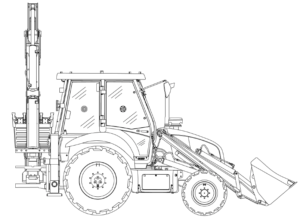
Complete workshop & service manual with electrical wiring diagrams for Case / IH Backhoe Loader 570T. It’s the same service manual used by dealers that guaranteed to be fully functional and intact without any missing page.
This Case / IH Backhoe Loader 570T service & repair manual (including maintenance, overhaul, disassembling & assembling, adjustment, tune-up, operation, inspecting, diagnostic & troubleshooting…) is divided into different sections. Each section covers a specific component or system with detailed illustrations. A table of contents is placed at the beginning of each section. Pages are easily found by category, and each page is expandable for great detail. The printer-ready PDF documents work like a charm on all kinds of devices.
1,243 pages, bookmarked, Searchable, Printable, high quality PDF
47576089 – Backhoe Loader 570T Service Manual.pdf
EXCERPT:
Contents
INTRODUCTION
Engine.. 10
[10.001] Engine and crankcase . . 10.1
[10.102] Pan and covers . . 10.2
[10.106] Valve drive and gears . . 10.3
[10.101] Cylinder heads . . 10.4
[10.105] Connecting rods and pistons. . 10.5
[10.103] Crankshaft and flywheel. . 10.6
[10.114] Pump drives . . 10.7
[10.216] Fuel tanks . . 10.8
[10.210] Lift pump and lines . . 10.9
[10.218] Fuel injection system. . 10.10
[10.220] Throttle linkage. . 10.11
[10.250] Turbocharger and lines. . 10.12
[10.254] Intake and exhaust manifolds and muffler . . 10.13
[10.400] Engine cooling system . . 10.14
[10.304] Engine lubrication system . . 10.15
[10.310] Aftercooler. . 10.16
Transmission.. 21
[21.100] Mechanical transmission lubrication system . . 21.1
[21.112] Power shuttle transmission. . 21.2
[21.134] Power shuttle transmission external controls . . 21.3
[21.154] Power shuttle transmission internal components . . 21.4
[21.700] Torque converter . . 21.5
Front axle system .. 25
[25.100] Powered front axle . . 25.1
[25.102] Front bevel gear set and differential . . 25.2
[25.108] Final drive hub, steering knuckles, and shafts . . 25.3
[25.400] Non-powered front axle . . 25.4
Rear axle system.. 27
[27.100] Powered rear axle. . 27.1
[27.106] Rear bevel gear set and differential . . 27.2
[27.124] Final drive hub, steering knuckles, and shafts . . 27.3
Brakes and controls .. 33
[33.202] Hydraulic service brakes . . 33.1
[33.110] Parking brake or parking lock . . 33.2
Hydraulic systems.. 35
[35.000] Hydraulic systems. . 35.1
[35.300] Reservoir, cooler, and filters. . 35.2
[35.104] Fixed displacement pump . . 35.3
[35.359] Main control valve . . 35.4
[35.724] Front loader hydraulic system control . . 35.5
[35.701] Front loader arm hydraulic system . . 35.6
[35.723] Front loader bucket hydraulic system . . 35.7
[35.726] Excavator and backhoe hydraulic controls. . 35.8
[35.736] Boom hydraulic system . . 35.9
[35.737] Dipper hydraulic system. . 35.10
[35.738] Excavator and backhoe bucket hydraulic system . . 35.11
[35.739] Swing arm hydraulic system . . 35.12
[35.AAA] Hydraulic systems generic sub-group . . 35.13
Frames and ballasting .. 39
[39.129] Stabilizers . . 39.1
Steering.. 41
[41.101] Steering control . . 41.1
[41.200] Hydraulic control components. . 41.2
[41.216] Cylinders . . 41.3
Wheels.. 44
[44.511] Front wheels. . 44.1
[44.520] Rear wheels . . 44.2
[44.AAA] Wheels generic sub-group . . 44.3
Cab climate control .. 50
[50.100] Heating . . 50.1
[50.200] Air conditioning. . 50.2
Electrical systems .. 55
[55.100] Harnesses and connectors. . 55.1
[55.201] Engine starting system . . 55.2
[55.301] Alternator. . 55.3
[55.518] Wiper and washer system. . 55.4
Front loader and bucket.. 82
[82.100] Arm. . 82.1
[82.300] Bucket . . 82.2
Booms, dippers, and buckets .. 84
[84.114] Boom pivoting support . . 84.1
[84.910] Boom . . 84.2
[84.912] Dipper arm . . 84.3
Platform, cab, bodywork, and decals .. 90
[90.150] Cab. . 90.1
[90.154] Cab doors and hatches . . 90.2
[90.156] Cab glazing . . 90.3
[90.100] Engine hood and panels . . 90.4
..
Frames and ballasting – Stabilizers
Stabilizers – Remove
PTIL13TLB1530FB 1
1. Park the machine on a flat surface.
2. Position the backhoe in fully stretched position.
3. Engage the stabilizers with the foot on the ground firmly.
4. Turn off the engine and remove the ignition key.
5. Disconnect the battery. Refer to Basic instructions ().
6. Release hydraulic pressure from the lines and hoses of the stabilizers by operating backhoe levers.
7. Remove stabilizer hydraulic connectors and plug them immediately.
8. Remove the bolt (1), washer (2), hexagonal nut (3) and mounting plate (4) from the top of the stabilizer to remove the light reflectors (5) on both sides.
9. Remove the upper plastic cover (6).
..

