INSTANT DOWNLOAD (add to cart)

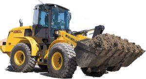
Complete workshop & service manual with electrical wiring diagrams for New Holland Wheel Loader W130, W130B, W130TC. It’s the same service manual used by dealers that guaranteed to be fully functional and intact without any missing page.
This New Holland Wheel Loader W130, W130B, W130TC service & repair manual (including maintenance, overhaul, disassembling & assembling, adjustment, tune-up, operation, inspecting, diagnostic & troubleshooting…) is divided into different sections. Each section covers a specific component or system with detailed illustrations. A table of contents is placed at the beginning of each section. Pages are easily found by category, and each page is expandable for great detail. The printer-ready PDF documents work like a charm on all kinds of devices.
1,609 pages, bookmarked, Searchable, Printable, high quality PDF
FILELIST:
604.07.242.50 – Flat Rate Time Manual (W110 – W130 – W170).pdf
604.13.492.00 – W130, W130TC Wheel Loader Workshop Manual.pdf
876347 59 A – EU – W130B Wheel Loader Workshop Manual.pdf
87751671 – Flat Time Rate Manual and Fault Code (W110B – W130B).pdf
EXCERPT:
SUMMARY
GENERALITIES…. Section 0
ENGINE …. Section 1
TRANSMISSION… Section 2
BRAKE SYSTEM…….. Section 3
STEERING SYSTEM …….. Section 4
BUCKET BOOMS AND FRAME …….. Section 5
EQUIPMENT HYDRAULIC SYSTEM ……. Section 6
ELECTRICAL SYSTEM…. Section 7
CAB …. Section 8
…
STEERING SYSTEM
4.6.3 CENTER PIVOT
Disassembly
1. Remove all dirt and grease from the area of the center pivot. Park the machine on a level surface.
2. Lower the bucket until the bucket is flat on the floor.
3. Stop the engine and apply the parking brake.
4. Remove the covers from both sides of the machine.
5. Disconnect the front wiring harness from the cab floor.
6. Remove any tie straps that fasten the front wiring harness to the chassis near the center pivot.
7. Loosen and remove the nut and washer that fasten the chassis ground wire and cab ground wire to the studs.
8. Loosen and remove the bolt, lock washer, and nut that fasten the clamp on the front wiring harness to the bracket on the rear frame. Move the front wiring harness out of the way.
9. Loosen and remove the fill plug for the hydraulic reservoir.
10. Connect a vacuum pump to the hydraulic reservoir. Start the vacuum pump.
11. Disconnect the brake hose from the backside of front brake line bracket.
12. Install a plug in the tube and a cap on the fitting.
13. Disconnect the hoses for the steering cylinder.
14. Install caps on the fittings and plugs in the hoses.
15. Loosen and remove the bolts, lock washers, and self-locking nuts that fasten the mounting bracket for the hoses to the bracket on the front frame.
16. Loosen and remove the bolts, flat washers, and self-locking nuts that fasten the bracket for the hoses to the rear frame.
17. Disconnect the return hose.
18. Install the cap on the hose and a plug in the fitting.
19. Disconnect the supply hose.
20. Install a cap on the hose and a plug in the fitting.
21. Stop the vacuum pump.
22. Loosen and remove the self-locking nut and bolt that hold the pivot pin for the steering cylinder rod eye.
23. Remove the pivot pin from the rear frame and the steering cylinder rod eye.
24. Remove the washer from the rear frame. Move the steering cylinder out of the way.
25. Repeat steps 22, 23 and 24 for the other steering cylinder.
26. Loosen and remove the Ferry head screws and retainers that fasten the drive shaft to the front yoke. Move the drive shaft out of the way.
27. Place two stands below and in contact with the front frame.
28. Install blocks between the rear axle and the rear frame on both sides of the machine to prevent the rear frame from tipping.
29. Put a jack in contact with both sides of the rear frame near the center pivot area. Use another jack at the rear of the machine to prevent the rear frame from tipping.
30. Loosen and remove the bolt (1), washer (2), and spacer (3) that fasten the upper pivot pin (4) to the rear chassis (5), refer to figure on page 7-34.
31. Use a prybar to remove the upper pivot pin (4).
32. Loosen and remove the bolts (1) and hardened washers (2) that fasten the lower pin plate (15) to the lower pivot pin (10).
33. Loosen and remove the cap screws (1) and washers (2) that fasten the lower pin plate (15) to the bottom of the rear chassis (5).
34. Use the ram and hand pump to remove the lower pivot pin (10).
35. Install the puller on the bottom spacer (14), see Special Tools on page 4-32.
…
