Posted on

Komatsu Motor Grader GD555, GD655, GD675 Workshop Repair & Service Manual

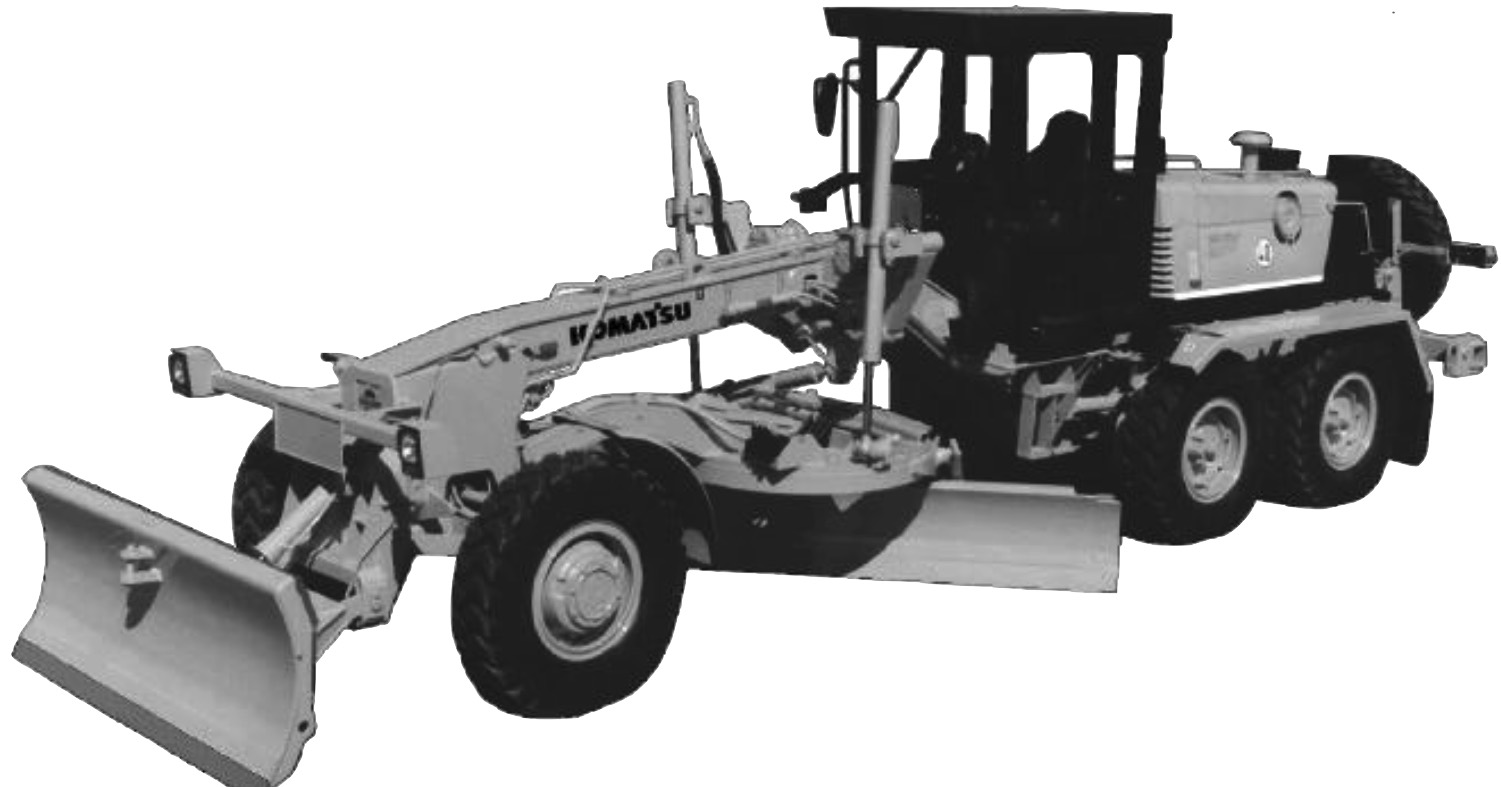
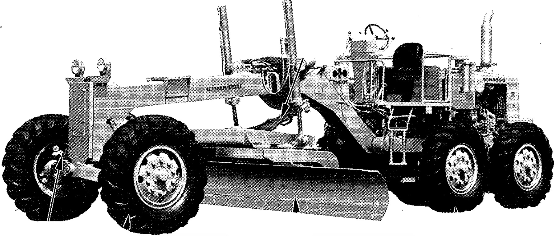
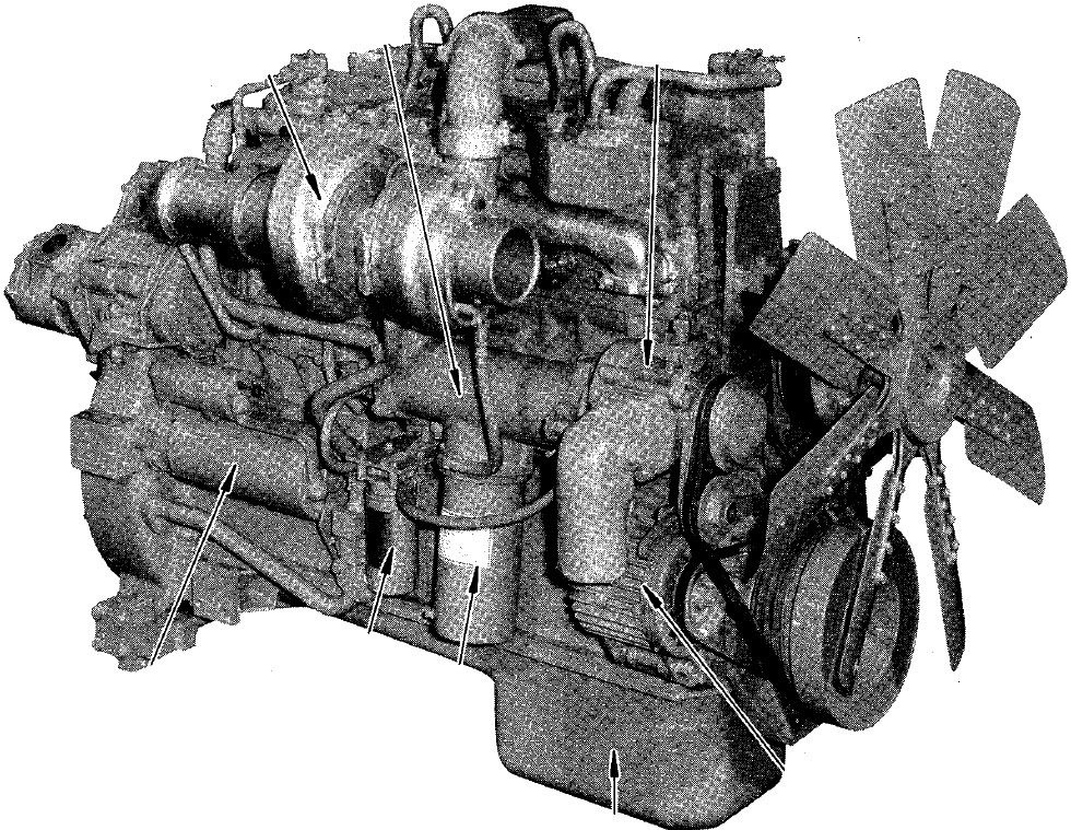
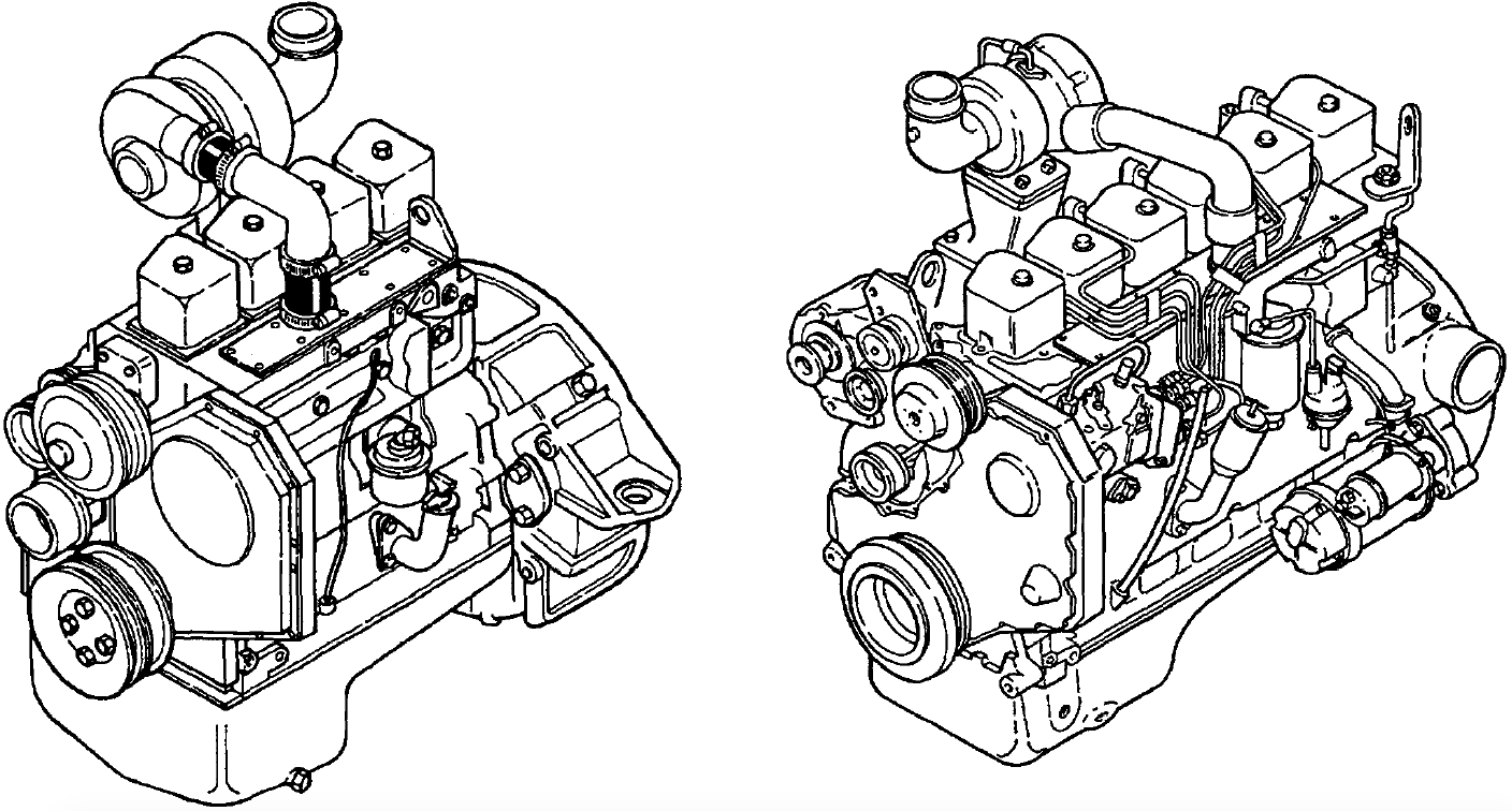
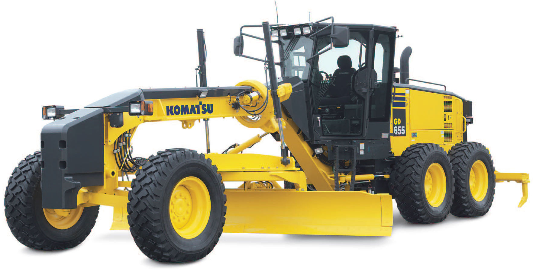
Komatsu GD555-3C, GD655-3C, GD675-3C Motor Grader

MKMTSGD555675OPEK.PDF
Price: $29.99 USD

Complete digital official shop manual contains service, maintenance, and troubleshooting information for the Komatsu GD555-3A, GD555-3C, GD555-5, GD655-3A, GD655-3C, GD655-3E0, GD655-5, GD675-3A, GD675-3C, GD675-3E0, GD675-5 Motor Grader. Diagnostic and repair procedures are covered in great detail to repair, maintain, rebuild, refurbish or restore your motor grader like a professional mechanic in local service/repair workshop. This cost-effective quality manual is 100% complete and intact as should be without any missing pages. It is the same factory shop manual used by dealers that guaranteed to be fully functional to save your precious time.

This manual for Komatsu Motor Grader GD555-3A, GD555-3C, GD555-5, GD655-3A, GD655-3C, GD655-3E0, GD655-5, GD675-3A, GD675-3C, GD675-3E0, GD675-5 is divided into different sections. Each section covers a specific component or system and, in addition to the standard service procedures, includes disassembling, inspecting, and assembling instructions. A table of contents is placed at the beginning of each section. Pages are easily found by category, and each page is expandable for great detail. It is in the cross-platform PDF document format so that it works like a charm on all kinds of devices. You do not need to be skilled with a computer to use the manual.

FILELIST:
GSAM042401 – Motoniveladora GALEO GD555-3A Manual de Operacion y Mantenimiento.pdf
GSBM021002 – GD555-3A, GD655-3A, GD675-3A Manual de Taller.pdf
KEAM037900 – Motor Grader GALEO GD655-3C Operation & Maintenance Manual.pdf
KEAM038000 – Motor Grader GALEO GD675-3C Operation & Maintenance Manual.pdf
KEAM038100 – Motor Grader GALEO GD555-3C Operation & Maintenance Manual.pdf
PEN00178-01 – Motor Grader GD555-3A Operation & Maintenance Manual.pdf
SEAM23DA03 – Motor Grader GD605A-1, GD655A-1 Operation & Maintenance Manual.pdf
SEAM023DUS01 – Motor Grader GD605A-3, GD655A-3 Operation & Maintenance Manual.pdf
SEAM037902T – Motor Grader GD655-3C Operation & Maintenance Manual.pdf
SEAM038002 – Motor Grader GD675-3C Operation & Maintenance Manual.pdf
SEAM038003 – Motor Grader GD675-3C Operation & Maintenance Manual.pdf
SEAM038102T – Motor Grader GD555-3C Operation & Maintenance Manual.pdf
SEAM042401 – Motor Grader GALEO GD555-3A Operation & Maintenance Manual.pdf
SEAM052800T – Motor Grader GALEO GD655-3A Operation & Maintenance Manual.pdf
SEBM020906 – Motor Grader GD555-3C, GD655-3C, GD675-3C Shop Manual.pdf
SEBM020909 – Motor Grader GD555-3C, GD655-3C, GD675-3C Shop Manual.pdf
SEBM021007 – Motor Grader GD555-3A, GD655-3A, GD675-3A Shop Manual.pdf
SEBM021008 – Motor Grader GD555-3A, GD655-3A, GD675-3A Shop Manual.pdf
SEN01775-05 – Motor Grader GD655-3E0, GD675-3E0 Shop Manual.pdf
SEN05215-06 – Motor Grader GD555-5, GD655-5, GD675-5 Shop Manual.pdf
TEN00095-01 – Motor Grader GALEO GD655-3C Operation & Maintenance Manual.pdf
TEN00149-05 – Motor Grader GD655-3E0 Operation & Maintenance Manual.pdf
TEN00150-05 – Motor Grader GD675-3E0 Operation & Maintenance Manual.pdf
TEN00177-02 – Motor Grader GD555-3A Operation & Maintenance Manual.pdf
TEN00178-02 – Motor Grader GD555-3C Operation & Maintenance Manual.pdf
TEN00179-02 – Motor Grader GD655-3A Operation & Maintenance Manual.pdf
TEN00368-01 – Motor Grader GD655-5 Operation & Maintenance Manual.pdf
TEN00369-01 – Motor Grader GD675-5 Operation & Maintenance Manual.pdf
TEN00445-02 – Motor Grader GD555-5 Operation & Maintenance Manual.pdf
TEN00446-02 – Motor Grader GD655-5 Operation & Maintenance Manual.pdf
TEN00447-02 – Motor Grader GD675-5 Operation & Maintenance Manual.pdf
TEN00448-00 – Motor Grader GD655-3E0 Operation & Maintenance Manual.pdf
TEN00449-01 – Motor Grader GD675-3E0 Operation & Maintenance Manual.pdf

EXCERPT:

STRUCTURE, FUNCTION AND MAINTENANCE STANDARD HYDRAULIC PUMP
FUNCTION
• The engine rotation and torque transmitted to the pump shaft is converted into hydraulic energy, and pressurized oil is discharged according to the load.
• It is possible to change the discharge amount by changing the swash plate angle.
STRUCTURE
• Cylinder block (7) is supported to shaft (1) by spline a, and shaft (1) is supported by the front and rear bearings.
• The tip of piston (6) is a concave ball, and shoe (5) is caulked to it to form one unit. Piston (6) and shoe (5) form a spherical bearing.
• Rocker cam (4) has flat surface A, and shoe (5) is always pressed against this surface while sliding in a circular movement. Rocker cam (4) brings high pressure oil at cylindrical surface B with cradle (2), which is secured to the case and forms a static pressure bearing when it slides.
• Piston (6) carries out relative movement in the axial direction inside each cylinder chamber of cylinder block (7).
• Cylinder block (7) seals the pressure oil to valve plate (8) and carries out relative rotation. This surface is designed so that the oil pressure balance is maintained at a suitable level.
The oil inside each cylinder chamber of cylinder block (7) is sucked in and discharged through valve plate (8).

OPERATION
1. Operation of pump
i) Cylinder block (7) rotates together with shaft (1), and shoe (5) slides on flat surface A.
When this happens, rocker cam (4) moves along cylindrical surface B, so angle between center line X of rocker cam (4) and the axial direction of cylinder block (7) changes. Angle is called the swash plate angle.
ii) Center line X of rocker cam (4) maintains swash plate angle in relation to the axial direction of cylinder block (7), and flat surface A moves as a cam in relation to shoe (5).
In this way, piston (6) slides on the inside of cylinder block (7), so a difference between volume E and F is created inside cylinder block (7). The suction and discharge is carried out by this difference F – E.
In other words, when cylinder block (7) rotates and the volume of chamber E becomes smaller, the oil is discharged during that stroke.
At the same time, the volume of chamber F becomes larger, and as the volume becomes larger, oil is sucked in.
(The diagram shows chamber F at the end of the suction process and chamber E at the end of the discharge process.)
iii) If center line X of rocker cam (4) is in line with the axial direction of cylinder block (7) (swash plate angle = 0), the difference between volumes E and F inside cylinder block (7) becomes 0, so the pump does not carry out any suction or discharge of oil. (In actual fact, the swash plate angle never becomes 0.)
iv) In other words, there is a proportional relationship between swash plate angle and the pump discharge amount.

Posted on

Komatsu Motor Grader GD530A(W), GD600R, GD605A-R, GD611-R, GD613A-R, GD615A, GD621A-R, GD622A, GD623A-R, GD625A, GD650A(W)-R, GD655A-R, GD661A, GD663A, GD670A(W), GD672A Factory Service & Shop Manual

Pages from SEBMG5250107 – Motor Grader GD510 & GD520 Series Shop Manual

MKMTSGD530670OPES.PDF
Price: $29.99 USD

Complete workshop & service manual with electrical wiring diagrams for Komatsu Motor Grader GD530A(W), GD600R, GD605A, GD605R, GD611A, GD611R, GD613A, GD613R, GD615A, GD621A, GD621R, GD622A, GD623A, GD623R, GD625A, GD650A(W), GD650R, GD655A, GD655R, GD661A, GD663A, GD670A(W), GD672A. It’s the same service manual used by dealers that guaranteed to be fully functional and intact without any missing page.

This Komatsu Motor Grader GD530A(W), GD600R, GD605A, GD605R, GD611A, GD611R, GD613A, GD613R, GD615A, GD621A, GD621R, GD622A, GD623A, GD623R, GD625A, GD650A(W), GD650R, GD655A, GD655R, GD661A, GD663A, GD670A(W), GD672A service & repair manual (including maintenance, overhaul, disassembling & assembling, adjustment, tune-up, operation, inspecting, diagnostic & troubleshooting…) is divided into different sections. Each section covers a specific component or system with detailed illustrations. A table of contents is placed at the beginning of each section. Pages are easily found by category, and each page is expandable for great detail. The printer-ready PDF documents work like a charm on all kinds of devices.

FILELIST:
CEAM003900 – Motor Grader with Emissionised Engine GD530A-2EY,AW-2EY & GD650A-2EY,AW-2EY & GD670A-2EY,AW-2EY Operation & Maintenance Manual.pdf
CEAM009700 – Motor Grader GD530A(W)-2B(C)Y & GD650A(W)-2B(C)Y & GD670A(W)-2B(C)Y Operation & Maintenance Manual.pdf
CEAMG65040 – Motor Grader GD530A(W)-2 & GD650A(W)-2 & GD670A(W)-2 Operation & Maintenance Manual.pdf
CEBM003902 – Motor Grader GD530A(W)-2 & GD650A(W)-2 & GD670A(W)-2 Shop Manual.pdf
CEBM009900 – Motor Grader GD530A(W)-2B(C)Y & GD650A(W)-2B(C)Y & GD670A(W)-2B(C)Y Shop Manual.pdf
CEBMG65194 – Motor Grader GD530A,AW & GD650A,AW & GD67OA,AW Shop Manual.pdf
SEAMG6150101 – Motor Grader GD625A-1 Operation & Maintenance Manual.pdf
SEBM023BA02 – Motor Grader GD600-1 Series Shop Manual.pdf
SEBMG6150109 – Motor Grader GD610 & GD620 & GD660 & GD670 Shop Manual.pdf

EXCERPT:
CONTENTS
01 GENERAL . . . . . . . . . 01-1
10 STRUCTURE AND FUNCTION . . . . . . . . . 10-1
20 TESTING, ADJUSTING AND TROUBLESHOOTING. . . . . . . . 20-1
30 DISASSEMBLY AND ASSEMBLY. . . . . . . . . . . 30-1
40 MAINTENANCE STANDARD . . . . . . . . . . 40-1
90 OTHER. . . . . . . . 90-1

DISASSEMBLY AND ASSEMBLY ALL-WHEEL-DRIVE PUMP
REBUILDING THE PUMP (OUT-OF-WARRANTY SERVICE)
If the pump requires rebuilding during the warranty timeframe, return the pump for an overhaul.
1. Remove the control device.
2. Remove the auxiliary pump. Mark the assembly position previously.
3. Mark the position of the index screw (1). Record the setting measure. Set the index screw to the disassembly position (2).
4. Mark the position of the connection plate. Loosen the connection plate fixation.
5. Lift off the port plate and control plate.
6. Press the cylinder to the bottom (1) and then remove the fixed indexing screw (2).
7. Push off the hydraulic section of the rotary group.
8. Remove the retaining ring and radial seal ring.

Posted on

Komatsu Motor Grader GD500, GD505, GD510, GD511, GD513, GD515, GD521, GD522, GD523, GD525 Factory Service & Shop Manual

Pages from SEBMG5250107 – Motor Grader GD510 & GD520 Series Shop Manual

MKMTSGD500OPES.PDF
Price: $29.99 USD

Complete workshop & service manual with electrical wiring diagrams for Komatsu Motor Grader GD500R-2, GD505R-2, GD505A-2, GD521A-1, GD522A-1, GD523A-1, GD525A-1, GD511A-1, GD513A-1, GD521R-1, GD523R-1, GD511R-1, GD513R-1, GD510R-1, GD515A-1, GD525A-1C, GD525A-1A, GD525A-1B. It’s the same service manual used by dealers that guaranteed to be fully functional and intact without any missing page.

This Komatsu Motor Grader GD500R-2, GD505R-2, GD505A-2, GD521A-1, GD522A-1, GD523A-1, GD525A-1, GD511A-1, GD513A-1, GD521R-1, GD523R-1, GD511R-1, GD513R-1, GD510R-1, GD515A-1, GD525A-1C, GD525A-1A, GD525A-1B service & repair manual (including maintenance, overhaul, disassembling & assembling, adjustment, tune-up, operation, inspecting, diagnostic & troubleshooting…) is divided into different sections. Each section covers a specific component or system with detailed illustrations. A table of contents is placed at the beginning of each section. Pages are easily found by category, and each page is expandable for great detail. The printer-ready PDF documents work like a charm on all kinds of devices.

SEAM23AB01 – Motor Grader GD500R-2 Series Operation & Maintenance Manual.pdf
SEAM236A01 – Motor Grader GD200A-1 Series Operation & Maintenance Manual.pdf
SEAMG5110103 – Motor Grader GD511A-1, GD521A-1, GD523A-1 Series Operation & Maintenance Manual.pdf
SEAMG5110104 – Motor Grader GD511A-1, GD521A-1, GD523A-1 Series Operation & Maintenance Manual.pdf
SEBM023AB07 – Motor Grader GD500-2 (GD500R-2, GD505R-2, GD505A-2) Series Shop Manual.pdf
SEBMG5250107 – Motor Grader GD510 & GD520 Series Shop Manual.pdf

EXCERPT:
OPERATION
1. Brake applied
When the brake pedal is depressed, the air circuit is connected to chamber A of the disc brake. When the air pressure is greater than the pushing force of spring (7), piston (9) moves to the left, and pushes discs (4) and plates (5). Friction is generated between the discs (meshed with gear (2)) and the plates (meshed with cage (1 0)). This slows down the rotation of the discs and finally stops it. In other words, the brake is applied.
2. Brake released
When the brake pedal is released, the air m chamber A is released. Spring (7) moves piston (9) back to the right, so the pushing force is reduced. This removes the friction between discs (4) and plates (5), and allows them to rotate freely. In other words, the brake is released.

Posted on

Komatsu TNV, N-855, EG Series Diesel Engines Factory Service & Shop Manual

Pages from WEBMTNV000 – TNV Series Diesel Engine (3D82AE_3D84E_3D88E_4D88E_4D98E_4D106_S4D84E_S4D98E_S4D106) Shop Manual

MKMTSENGMISCOPES.PDF
Price: $29.99 USD

Complete workshop & service manual with electrical wiring diagrams for Komatsu TNV, N-855, EG Series Diesel Engines. It’s the same service manual used by dealers that guaranteed to be fully functional and intact without any missing page.

This Komatsu TNV, N-855, EG Series Diesel Engines service & repair manual (including maintenance, overhaul, disassembling & assembling, adjustment, tune-up, operation, inspecting, diagnostic & troubleshooting…) is divided into different sections. Each section covers a specific component or system with detailed illustrations. A table of contents is placed at the beginning of each section. Pages are easily found by category, and each page is expandable for great detail. The printer-ready PDF documents work like a charm on all kinds of devices.

WEBMTNV000 – TNV Series Diesel Engine (3D82AE_3D84E_3D88E_4D88E_4D98E_4D106_S4D84E_S4D98E_S4D106) Shop Manual.pdf
SEBM06500A02 – EG Series Engine Generators Shop Manual.pdf
SEBE6710A03 – Komatsu-N-855 Series Diesel Engine Shop Manual.pdf
SEBDCOMP009 – Komatsu Component of Engine Shop Manual.pdf

EXCERPT:
TABLE OF CONTENTS
01 GENERAL …… 01-1
02 STRUCTURE AND FUNCTION ……. 02-1
03 CHECK … 03-1
04 TROUBLESHOOTING .. 04-1
05 ASSEMBLY … 05-1

PERIODIC INSPECTION
As even a healthy man receives periodic examinations to maintain his health and to discover a disease in an early stage, so an engine generator requires periodic inspections to maintain its performance and to discover a trouble in an early stage. While the periodic inspection timings are specified in this manual and the instruction manual, it is important to conduct periodic inspections regardless of the inspection and servicing timings if it was recognized as necessary in view of the operating conditions of the machine or its activity rate, the daily inspection, etc.
Described in this chapter are the cautions when inspecting the generator and the handling of the engine cooling water, fuel, and oil. Table 3.1 shows the inspection and servicing list for your reference.
1. AC GENERATOR
The generator, which is prone to be damaged by moisture, oil, dust, etc., must always be kept dry and clean. To clean the generator, a dry cloth should be used instead of a cloth dampened with water or oil. When using compressed air, use dry air, and clean the machine interior beforehand. (We recommend to use an electric vacuum cleaner.)
During the daily inspection check abnormal noise generation from the generator, odor, abnormal vibration, etc. by using a screwdriver or a rod. Also check by using a torque wrench at least once every six months that the engine coupling, which is an important part, is tightened to the specified torque.

Posted on

Komatsu KDC 410 & KDC 610 & KDC 614 Series Engine Factory Service & Shop Manual

Pages from CEBM614SH0 – KDC 614 Series Engine (1991 Series) Shop Manual

MKMTSENGKDCOPES.PDF
Price: $29.99 USD

Complete workshop & service manual with electrical wiring diagrams for Komatsu KDC 410 & KDC 610 & KDC 614 Series Engine. It’s the same service manual used by dealers that guaranteed to be fully functional and intact without any missing page.

This Komatsu KDC 410 & KDC 610 & KDC 614 Series Engine service & repair manual (including maintenance, overhaul, disassembling & assembling, adjustment, tune-up, operation, inspecting, diagnostic & troubleshooting…) is divided into different sections. Each section covers a specific component or system with detailed illustrations. A table of contents is placed at the beginning of each section. Pages are easily found by category, and each page is expandable for great detail. The printer-ready PDF documents work like a charm on all kinds of devices.

FILELIST:
CEBM610SH0 – KDC 410 & KDC 610 Series Engine (1991 Series) Shop Manual.pdf
CEBM610TR0 – KDC 410 & KDC 610 Series Engine (1991 Series) Troubleshooting & Repair Manual.pdf
CEBM614SH0 – KDC 614 Series Engine (1991 Series) Shop Manual.pdf
CEBM614TR1 – KDC 614 Series Engine (1991 Series) Troubleshooting & Repair Manual.pdf

EXCERPT:
TABLE OF CONTENTS
Introduction . . . 1
Engine Identification . . . . E
Engine Disassembly and Assembly – Group 00 . . . . . . . 0
Cylinder Block – Group 01 . . . . 1
Cylinder Head – Group 02 . . . . 2
Rocker Levers – Group 03 . . . . 3
Cam Followers – Group 04 . . . . 4
Fuel System – Group 05 . . . . 5
Injectors and Fuel Lines – Group 06 . . . . . 6
Lubricating Oil System – Group 07 . . . . . . 7
Cooling System – Group 08 . . . . . . . . . 8
Drive Units – Group 09 . . . . . 9
Air Intake System – Group 10 . . . . . . . . 10
Exhaust System – Group 11 . . . . . . . . . 11
Air Equipment – Group 12 . . . 12
Electrical Equipment – Group 13 . . . . . . 13
Engine Testing – Group 14 . . . 14
Instruments and Controls – Group 15 . . . . . 15
Mounting Adaptations – Group 16 . . . . . 16
Specifications and Torque Values – Group 18 . . . . . . . . . 18
Service Literature . . . . . . L
Index . . . ..X

Viscous Vibration Damper – Cleaning
Warning: When using a steam cleaner, wear protective clothing and safety glasses or a face shield. Hot steam will cause serious personal injury.
Clean the vibration damper with a solvent cleaner or steam clean. Dry with compressed air.
Viscous Vibration Damper – Inspection
Check the mounting web for cracks. Check the housing for dents or raised surfaces. Replace the vibration damper if any of these defects are identified.