Posted on

John Deere Tractor 5080R(N), 5090R(N), 5100R(N) Repair Service Manual (TM401819)


INSTANT DOWNLOAD


Complete service repair manual for John Deere Tractor 5080R, 5090R, 5100R, 5080RN, 5090RN, 5100RN, with all the shop information to maintain, repair, and rebuild like professional mechanics.

John Deere Tractors 5100RN, 5080RN, 5090RN, 5080R, 5090R, 5100R workshop service & repair manual includes:
* Numbered table of contents easy to use so that you can find the information you need fast.
* Detailed sub-steps expand on repair procedure information
* Numbered instructions guide you through every repair procedure step by step.
* Notes, cautions and warnings throughout each chapter pinpoint critical information.
* Bold figure number help you quickly match illustrations with instructions.
* Detailed illustrations, drawings and photos guide you through every procedure.
* Enlarged inset helps you identify and examine parts in detail.

tm401816 – Traktory 5080R-5100R a 5080RN-5100RN Opravy Czech.pdf
tm401818 – Trekkers 5080R-5100R en 5080RN-5100RN Reparatie Dutch.pdf
TM401819 – John Deere Tractor 5080R, 5090R, 5100R, 5080RN, 5090RN, 5100RN Technical Manual (Repair).PDF
tm401822 – Traktorit 5080R-5100R ja 5080RN-5100RN Korjaus Finnish.pdf
tm401828 – Tracteurs 5080R-5100R et 5080RN-5100RN Réparation French.pdf
tm401829 – Traktoren 5080R-5100R und 5080RN-5100RN Reparatur German.pdf
tm401839 – Riparazioni trattori 5080R-5100R e 5080RN-5100RN Italian.pdf
tm401858 – Tractoare 5080R-5100R şi 5080RN-5100RN Reparare Romanian.pdf
tm401867 – 5080R-5100R och 5080RN-5100RN Traktorer Reparation Swedish.pdf
tm401874 – Traktor 5080R-5100R og 5080RN-5100RN Reparation Danish.pdf
tm401876 – Opravytraktorov 5080R-5100R a 5080RN – 5100RN -: (Európska verzia) Slovak.pdf
tm401878 – 5080R-5100R og 5080RN-5100RN traktorer Reparasjoner Norwegian.pdf
tm401880 – 5080R-5100R ve 5080RN-5100RN TraktörlerOnarım -: (Avrupa Sürümü) Turkish.pdf
tm401882 – Traktorji 5080R-5100R in 5080RN-5100RNPopravilo -: (Evropska izvedba) Slovenian.pdf
tm4018a5 – Traktori 5080R-5100R i 5080RN-5100RN Popravak Croatian.pdf

Total Pages: 1,356 pages
File Format: PDF/EPUB/MOBI/AZW (PC/Mac/Android/Kindle/iPhone/iPad; bookmarked, ToC, Searchable, Printable)
Language: English etc.

MAIN SECTIONS
Foreword
Safety
Safety Measures
General Information
Specifications
Tests and Adjustments
Predelivery Inspection
Engine
Removal and Installation of Components
Fuel, Air Intake, Cooling and Exhaust Systems
Removal and Installation of Components
Speed Control Linkage
Fuel System
Air Intake System
Cooling System
Cold-Weather Starting Aids
Exhaust System
Electrical System
Connectors
Alternator
Starter Motor
Electrical Components
Electronic Control Units
Removal and Installation of Electronic Control Units
Removal and Installation of Terminating Resistors
PowrQuad Transmission
Removal and Installation of Components
Transmission Shift Controls
PowrQuad Module
Reduction Gear
Range Transmission
Drive Systems
Removal and Installation of Components
U-Jointed Shafts and Torsion Damper
Front-Wheel Drive Clutch
Differential
Hydraulic Pump Drive
Final Drives
Rear PTO
Front PTO
Steering and Brakes
Hydrostatic Steering
Brake Valve
Rear Brakes
Park Brake
Hydraulic Trailer Brake
Air Brake System
Hydraulic System
Controls
Hydraulic Pump
Valves
Hitch
Selective Control Valves (SCVs) and Couplers
Miscellaneous
Removal and Installation of Components
Front and Rear Wheels
Trailer Mounting and Swinging Drawbar
Pick-Up Hitch
Front Hitch
Front Loader
Operator’s Cab
Removal and Installation of Components
Controls and Instruments
Air-Conditioning System
Heating System
Seats
Operator’s Cab
Parts for Electronic Hitch Control
Special Tools
Special Tools (Dealer-Fabricated)
Special Tools (Available as Spare Part)

tm401819 – 5080R-5100R and 5080RN-5100RN Tractors Repair
Table of Contents
Foreword
Section 05: Safety
Group 05: Safety Measures
Recognize Safety Information
”Important” Information
”Note” Information
Prevent Machine Runaway
Handle Fluids Safely—Avoid Fires
Prevent Battery Explosions
Prepare for Emergencies
Prevent Acid Burns
Avoid High-Pressure Fluids
Service Cooling System Safely
Remove Paint Before Welding or Heating
Avoid Heating Near Pressurized Fluid Lines
Work In Ventilated Area
Wear Protective Clothing
Practice Safe Maintenance
Park Machine Safely
Use Proper Lifting Equipment
Construct Dealer-Made Tools Safely
Support Machine Properly
Work in Clean Area
Illuminate Work Area Safely
Service Machines Safely
Use Proper Tools
Service Tires Safely
Service Front-Wheel Drive Tractor Safely
Safety Information – Air Brake System
Avoid Eye Contact With Radar
Keep ROPS Installed Properly
Replace Safety Signs
Dispose of Waste Properly
Live With Safety
Safety Measures on Electronic Control Units
Section 10: General Information
Group 05: Specifications
Engine Specifications
Cooling System
Electronic Fuel System with Common Rail (Denso)
Air Intake System
Electrical System
Hydrostatic Steering
Clutch
Transmission
Reduction Gear
Rear PTO
Front PTO
Differential
Differential Lock
Final Drives
Front-Wheel Drive
Hydraulic Brakes
Park Brake
Parking Lock
Hydraulic System
Rockshaft
Front Hitch
Ground Travel Speeds
Front and Rear Wheels
Dimensions and Weights
Capacities
Handling and Storing Diesel Fuel
Diesel Fuel
Biodiesel Fuel
Lubricity of Diesel Fuel
Diesel Engine Break-In Oil
Diesel Engine Oil
Transmission and Hydraulic Oil
Front-Wheel Drive Axle Oil
Diesel Engine Coolant
Supplemental Coolant Additives
Grease
Oil Filters
Mixing of Lubricants
Lubricant Storage
Operating in Warm Temperature Climates
Alternative and Synthetic Lubricants
Unified Inch Bolt and Screw Torque Values
Metric Bolt and Screw Torque Values
Hydraulic system inch fitting torques
Hydraulic system metric fitting torques
Product Identification Number
Engine Serial Number
Transmission Serial Number
Front-Wheel Drive Axle Serial Number
Operator’s Cab Serial Number
Operator’s seat serial number
Sub-assembly serial numbers
Group 10: Tests and Adjustments
General Information – Tune-Up, Summary of References
Specifications
Using High-Pressure Washers
Preliminary Engine Test
Preliminary Fuel System Test
Clean Dust Unloading Valve
Engine Air Cleaner
Cleaning the Primary Filter Element
Cleaning a Dusty Element
Secondary (Safety) Element
Check Air Intake System Connections for Leaks
Check Crankcase Vent Hose for Clogging
Clean the Radiator Grille Screen
Clean Radiator
Check Caps on Expansion Tank
Check Radiator for Leaks
Check Engine Thermostat
Check Operation of Fuel Transfer Pump
Check Fuel Filter
Bleed Fuel System
Clean Water Trap
Clean Battery, Cables and Battery Box with Clean Cloth
Check Neutral Start Circuit
Check Starting Motor Operation
Checking the Lighting Circuit
Final Engine Check
Tractor Operation Check
Group 15: Predelivery Inspection
Predelivery Inspection
Section 20: Engine
Group 00: Removal and Installation of Components
Engine – Removal and Installation of Components, Summary of References
Special Tools
Specifications
Remove the Engine
Install the Engine
Engine Mounting
Section 30: Fuel, Air Intake, Cooling and Exhaust Systems
Group 00: Removal and Installation of Components
Fuel, Air Intake, Cooling and Exhaust Systems – Removal and Installation of Components, Summary of References
Specifications
Remove Engine Hood
Install Engine Hood
Remove Battery
Install Battery
Remove and Install Front Frame
Front Frame – Remove Front Section
Front Frame – Install Front Section
Front Frame – Remove Center Section
Front Frame – Install Center Section
Front Frame – Remove Hood Carrier
Front Frame – Install Hood Carrier
Group 05: Speed Control Linkage
Speed Control, Summary of References
Accelerator Pedal Potentiometer, Removal and Installation
Hand Throttle Potentiometer, Removal and Installation
Group 10: Fuel System
Fuel System, Summary of References
Fuel System – General Information
Remove Fuel Tank
Install Fuel Tank
Replace Fuel Level Sending Unit
Replace Fuel Transfer Pump
Replace Fuel Filter
Bleed Fuel System
Group 15: Air Intake System
Air Intake System – Summary of References
General Information
Check Dust Unloading Valve
Air Cleaner, Removal and Installation
Air Intake Hoses, Removal and Installation
Replace Sending Unit for Air Cleaner Restriction (B02)
Remove Charge Air Cooler
Install Charge Air Cooler
Remove Charge Air Cooler Fan
Install Charge Air Cooler Fan
Group 20: Cooling System
Cooling System – Summary of References
General Information
Specifications
Remove Radiator
Install Radiator
Change Viscous Clutch of Fan
Thermostat and Temperature Sensor, Removal and Installation
Drain Coolant
Add Coolant
Relieve Drive Belt Tension
Replace Drive Belt
Replace the Drive Belt Tensioner
Recondition the Fan Console
Group 25: Cold-Weather Starting Aids
Cold-Weather Starting Aids – Summary of References
Fuel Preheater
Electrical Starting Aid
Coolant Heater
Transmission Preheater
Group 30: Exhaust System
Exhaust System, Summary of References
Exhaust System – General Information
Exhaust System – Install Muffler
Exhaust System – Exhaust Pipe on Right of Cab Frame
Exhaust System – Exhaust Pipe to Top Right
Exhaust System – Exhaust Pipe to Bottom Right
Section 40: Electrical System
Group 05: Connectors
Connectors – Reconditioning (Summary of References)
Special Tools
General
Using high-pressure washers
Disconnecting electrical circuits
Strip Wire Ends
Installing a Terminal
METRI PACK Connector With Terminal Lock at the Rear
METRI PACK Connectors
Connectors for Electronic Control Units
Connectors
CRIMP SNAP IN Connectors
DEUTSCH Connectors
Individual Terminals
Fuse and Relay Boxes
Group 10: Alternator
Alternator – Reconditioning (Summary of References)
Special Tools
Specifications
Repairing the Alternator
Disconnecting Electrical Circuits
Relieve Drive Belt Tension
Remove/Install the Alternator
Pulley Removal and Installation
Group 15: Starter Motor
Starting Motor – Reconditioning (Summary of References)
Specifications
Repairing the Starter Motor
Disconnecting Electrical Circuits
Remove and Install Starting Motor
Group 20: Electrical Components
Electrical Components – Reconditioning (Summary of References)
General Information
Disconnecting electrical circuits
Adjusting the Headlights
Adjust Lights on the Cab Frame
Safety Instructions for Replacing a Halogen Bulb
Section 45: Electronic Control Units
Group 05: Removal and Installation of Electronic Control Units
Electronic Control Units – Summary of References
Instructions when Replacing a Control Unit
Instructions when Replacing a VIN Control Unit
Safety Information
Replace BCU Control Unit
Replace BIF Control Unit
Replace ECU Control Unit
Replace EPC Control Unit
Replace PRF Control Unit
Group 10: Removal and Installation of Terminating Resistors
Terminating Resistors – Summary of References
Terminating Resistors – CAN-BUS System
Section 55: PowrQuad Transmission
Group 00: Removal and Installation of Components
PowrQuad Transmission – Removal and Installation of Components, Summary of References
PowrQuad Transmission – Removal and Installation of Components, Special Tools
PowrQuad Transmission – Removal and Installation of Components, Specifications
PowrQuad Plus Transmission, Removal and Installation
AutoQuad Plus Transmission, Removal and Installation
Remove PowrQuad Transmission
Install PowrQuad Transmission
Remove Reduction Gear
Install Reduction Gear
Remove Range Transmission
Install Range Transmission
Group 05: Transmission Shift Controls
PowrQuad Transmission – Transmission Shift Controls, Summary of References
PowrQuad Transmission – Transmission Shift Controls, Specifications
Recondition Range Shift Linkage (Shift Elements)
Recondition Range Shift Linkage (Lever and Gate)
PowrQuad Transmission – Check and Adjust the Shift Mechanism/Linkage and the Park Lock
Reduction Gear – Recondition Actuator
Reduction Gear – Adjust Shift Mechanism
Repair Clutch Actuation Mechanism
Group 10: PowrQuad Module
PowrQuad Module – Summary of References
Special Tools, Summary of References
Specifications
Transmission Sub-Assemblies
Replace Temperature Sensor and Pressure Switches
Remove and Install Oil Filter Housing
Replace Oil Filter
Remove and Install Front Valve Housing
Remove and Install the Valves in the Front Valve Housing
Remove and Install Front Transmission Cover
Remove and Install the Valves in the Front Transmission Cover
Remove and Install Shift Valve Housing
Remove and Install the Valves in the Shift Valve Housing
Remove Transmission Oil Pump
Recondition Transmission Oil Pump
Install Transmission Oil Pump
Remove the Gear-Shift Planetary Drive
Recondition the Gear-Shift Planetary Drive
Install the Gear-Shift Planetary Drive
Remove the B1 Brake Housing
Recondition the B1 Brake
Install the B1 Brake Housing
Remove the B2-B3 Brake Housing
Recondition the B2 Brake
Recondition the B3 Brake
Install the B2-B3 Brake Housing
Remove the C4 Clutch
Recondition the C4 Clutch
Install the C4 Clutch
Remove the Reverse Brake
Recondition Reverse Brake
Install the Reverse Brake
Remove the Forward Clutch with Planetary Drive (Forward/Reverse)
Recondition Forward Clutch with Planetary Drive (Forward/Reverse)
Install the Forward Clutch with Planetary Drive (Forward/Reverse)
Replace the Clutch Carriers for the C4 Clutch and the Forward Clutch
Replace the Transmission Output Shaft and Rear PTO Drive Shaft
Group 15: Reduction Gear
Reduction Gear – Summary of References
Exploded View of Reduction Gear
Recondition Reduction Gear
Pre-Assembly of Reduction Gear
Measure the Gaps at the Reduction Gear Connecting Ring
Remove and Install Bearing of Reduction Gear Countershaft
Group 25: Range Transmission
Range Transmission – Summary of References
Range Transmission – Specifications
Range Transmission – Sectional View
Recondition Range Transmission, Preliminary Work
Recondition Range Transmission
Assemble Range Transmission
Recondition the Shift Cover
Replace Transmission Speed Sensor (B104)
Section 56: Drive Systems
Group 00: Removal and Installation of Components
Drive Systems – Removal and Installation of Components, Summary of References
Drive Systems – Removal and Installation of Components, Special Tools
Drive Systems – Removal and Installation of Components, Specifications
Remove Front-Wheel Drive Clutch
Install Front-Wheel Drive Clutch
Remove Differential Housing
Install Differential Housing
Remove Final Drives
Install Final Drives
Remove Rear PTO
Install Rear PTO
Remove Front PTO
Install Front PTO
Group 05: U-Jointed Shafts and Torsion Damper
U-Jointed Shafts and Torsion Damper – Summary of References
U-Jointed Shafts and Torsion Damper – Special Tools
Use of Special Tool KJD10426
U-Jointed Shafts and Torsion Damper – Specifications
Remove U.j. Shaft (Front-Wheel Drive)
Install U.j. Shaft (Front-Wheel Drive)
Disassemble U.j. Shaft (Front-Wheel Drive)
Assemble U.j. Shaft (Front-Wheel Drive)
Remove Engine U.j. Shaft
Install Engine U.j. Shaft
Remove Torsion Damper
Install Torsion Damper
Change Torsion Damper Bearings
Group 10: Front-Wheel Drive Clutch
Front-Wheel Drive Clutch – Summary of References
Front-Wheel Drive Clutch – Special Tools
Front-Wheel Drive Clutch – Specifications
Replace Wheel Speed Sensor B35
Replace Front-Wheel Drive Solenoid Valve Y03
Front-Wheel Drive Clutch – Sectional View
Front-Wheel Drive Clutch – Exploded View
Disassemble Front-Wheel Drive Clutch
Recondition the Front Wheel Drive Clutch
Assemble Front-Wheel Drive Clutch
Group 15: Differential
Differential – Reconditioning, Summary of References
Differential – Specifications
Remove Differential Lock
Install Differential Lock
Remove Differential
Install Differential
Differential and Differential Lock – Sectional View
Differential and Differential Lock – Exploded View
Disassemble Differential Lock
Assemble Differential Lock
Disassemble Differential
Assemble Differential
Group 20: Hydraulic Pump Drive
Hydraulic Pump Drive – Reconditioning, Summary of References
Hydraulic Pump Drive – Specifications
Remove Hydraulic Pump Drive
Hydraulic Pump Drive – Exploded View
Install Hydraulic Pump Drive
Group 25: Final Drives
Final Drives – Summary of References
Final Drives – Special Tools
Final Drives – Specifications
Final Drives – Sectional View
Final Drives – Exploded View
Final Drives – Remove Planetary Carrier
Final Drives – Recondition Planetary Carrier
Final Drives – Install Planetary Carrier
Final Drives – Adjust Rolling Drag Torque
Disassemble Final Drives
Assemble Final Drives
Group 30: Rear PTO
Rear PTO – Reconditioning, Summary of References
Rear PTO – Special Tools
Other Material
Rear PTO – Specifications
Replace Output Shaft Seal Ring
Remove PTO Clutch
Exploded View of PTO Clutch
Repair PTO Clutch
Install PTO Clutch
Disassemble PTO Drive Train
Recondition Output Shaft, 540/540E/1000 rpm
Recondition Output Shaft, 540/540E rpm – Exploded View
Recondition Countershaft (540/540E rpm and 540/540E/1000 rpm)
Assemble PTO Shifter (540/540E rpm and 540/540E/1000 rpm)
Assemble Drive Train
Install Support and Adjust Taper Roller Bearings
Remove PTO Modulating Valve
Recondition PTO Modulating Valve
Install PTO Modulating Valve
Recondition Solenoid Valve
Replace PTO Speed Sending Unit
Change and Adjust Bowden Cable
Group 35: Front PTO
Front PTO – Summary of References
Front PTO – Specifications
Front PTO – General Repair Procedures
Front PTO – Clean Oil Screen
Front PTO – Replace Solenoid Valve (Y01)
Front PTO – Remove Oil Pump
Front PTO – Exploded View of Oil Pump
Front PTO – Install Oil Pump
Front PTO – Sectional View
Disassemble Front PTO
Assemble Front PTO
Front PTO – Disassemble Clutch
Front PTO – Assemble Clutch
Front PTO – Remove Constant-Velocity Joint from Drive Shaft
Front PTO – Install Constant-Velocity Joint on Drive Shaft
Front PTO – Remove Oil Cooler
Front PTO – Install Oil Cooler
Section 60: Steering and Brakes
Group 05: Hydrostatic Steering
Hydrostatic Steering – Summary of References
Special Tools
Specifications
Disconnect/Connect Steering or Brake Hoses
Remove and Install Steering Unit
Steering Unit Components
Remove Steering Wheel
Install Steering Wheel
Remove Panels from Steering Column
Install Panels on Steering Column
Repair Steering Column
Group 15: Brake Valve
Brake Valve – Summary of References
Specifications
Remove and Install Brake Valve
Group 20: Rear Brakes
Rear Brakes – Summary of References
Special Tools
Remove Rear Brakes
Install Rear Brakes
Bleed Air from Brakes
Group 25: Park Brake
Park Brake – Summary of References
Park Brake – Special Tools
Park Brake – Specifications
Remove Park Brake
Disassemble Park Brake
Park Brake – Exploded View
Assemble Park Brake
Install Park Brake
Remove Brake Lever of Park Brake
Install Brake Lever of Park Brake
Park Brake – Components
Check and Adjust Park Brake
Group 30: Hydraulic Trailer Brake
Hydraulic Trailer Brake – Summary of References
Hydraulic Trailer Brake – Specifications
Hydraulic Trailer Brake – Instructions on Repair
Hydraulic Trailer Brake – Change Trailer Brake Valve
Hydraulic Trailer Brake – Clean the Screen
Hydraulic Trailer Brake – Change Check Valve
Hydraulic Trailer Brake – Change Control Head
Bleed Air from Hydraulic Trailer Brake Valve
Check Hydraulic Trailer Brake Valve
Group 35: Air Brake System
Air Brake System – Summary of References
Specifications
Safety Information When Working on the Air Brake System
Screw Union Installation
Change Air Compressor
Gasket Set for Air Compressor
Change Compressed-Air Tank
Replace the Pressure-Regulating Valve
Change Trailer Control Valve
Change Coupling Ends
Air Brake Test Procedure
Section 70: Hydraulic System
Group 05: Controls
Hydraulic System – Controls (Summary of References)
Selective Control Valves – Remove and Install the Actuating Elements
Selective Control Valve – Adjust the Bowden Cable
Remove and Install the Multi-Function Lever
Adjust Multi-Function Lever
Group 10: Hydraulic Pump
Hydraulic Pump – Summary of References
Specifications
Remove Hydraulic Pump
Recondition Hydraulic Pump
Install Hydraulic Pump
Group 15: Valves
PC Hydraulic System – Recondition Valves, Summary of References
Hydraulic System — General Instructions on Safety and Repair
Remove Priority Valve Block
Recondition Priority Valve Block
Install Priority Valve Block
Group 20: Hitch
Hitch – Summary of References
Recondition Rockshaft – Special Tools, Summary of References
Other Material
Hitch – Specifications
Hitch – Direct Control
Remove Hitch Valve
Recondition the Rockshaft Valve
Install Hitch Valve
Hitch Valve – Remove the Stepper Motor
Hitch Valve – Install the Stepper Motor
Hitch Valve – Center the Stepper Motor
Hitch – Remove and Install the Position Sensor and Toothed Segment
Remove and Install Rockshaft Housing
Removal and installation
Remove Rockshaft Cylinders
Install Rockshaft Cylinders
Remove and Install Draft Sensor and Draft Link Bearing Pins
Automatic Stabilizer Rod
Stabilizing Rod Bracket
Group 25: Selective Control Valves (SCVs) and Couplers
Selective Control Valves (SCVs) and Couplers – Summary of References
Selective Control Valves (SCVs) and Couplers – Specifications
Repair the Selective Control Valves (SCVs) and Couplers – General Instructions on Safety and Reconditioning
Selective Control Valves (SCVs) – Identification
Remove the Selective Control Valves (SCVs)
Install Selective Control Valves (SCVs)
Recondition Selective Control Valves (SCV 105)
Recondition Selective Control Valves (SCV 205)
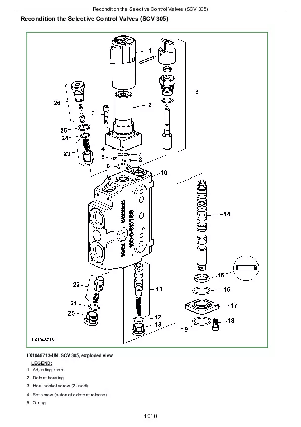
Recondition the Selective Control Valves (SCV 305)
Selective Control Valves (SCVs) – Reconditioning the Couplers
Selective Control Valves for Front Loader – Identification
Remove Selective Control Valves for Front Loader
Install Selective Control Valves for Front Loader
Install a Front Loader
Section 80: Miscellaneous
Group 00: Removal and Installation of Components
Miscellaneous – Removal and Installation of Components, Summary of References
Miscellaneous – Removal and Installation of Components, Special Tools
Miscellaneous – Removal and Installation of Components, Specifications
Remove Main Frame
Install Main Frame
Remove Front Hitch
Install Front Hitch
Remove the Front-Wheel Drive Axle
Install the Front-Wheel Drive Axle
Remove Front Axle Support
Install Front Axle Support
Group 15: Front and Rear Wheels
Special or Essential Tools
Specifications
Front Wheels, Rear Wheels and Fenders—Reconditioning (Summary of References)
Remove Front and Rear Wheels
Recondition Front and Rear Wheels
Install Front and Rear Wheels
Pivoting (Front) Fender
Group 20: Trailer Mounting and Swinging Drawbar
Trailer Mounting and Swinging Drawbar – Reconditioning, Summary of References
Trailer Mounting and Swinging Drawbar, Reconditioning, Specifications
Check the Manually-Operated Trailer Hitch for Wear
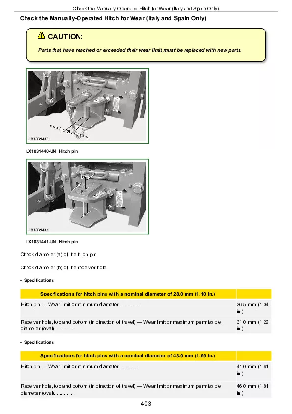
Checking the Manually-Operated Hitch for Wear (Italy and Spain Only)
Check Remote Controlled Trailer Hitch for Wear
Checking the Tow-Hook for Wear
Check the Swinging Drawbar for Wear
Install the Center Link Support
Guide Rails for Height-Adjustable Trailer Hitch
Repair of Automatic Trailer Hitch
Remote Control for Automatic Trailer Hitch
Swinging Drawbar
Proper Use of Drawbar
Swinging Drawbar with Pick-Up Hitch
Group 30: Pick-Up Hitch
Pick-Up Hitch — Summary of References
Specifications
Other Material
Check Tow Hook on Pick-Up Hitch for Wear
Install Pick-Up Hitch
Adjust the Lift Links
Check and Adjust the Retainer Spring
Recondition the Latch Housing
Repairing the Hydraulic Cylinder
Adjust the Guide Stop
Adjust the Locking Pin
Operational Check of Pick-Up Hitch
Group 40: Front Hitch
Front Hitch – Reconditioning (Summary of References)
Remove and Install Bracket for Mowing Unit Suspension
Lines and Hoses of Front Hitch, Removal and Installation (without Multi-Valve)
Lines and Hoses of Front Hitch, Removal and Installation (with Multi-Valve)
Remove and Install Front Hitch Multi-Valve
Remove and Install Front Hitch Accumulator
Service Front Hitch Accumulator
Remove Front Hitch Cylinders
Install Front Hitch Cylinders
Recondition Front Hitch Cylinders
Recondition Front Hitch Joint
Group 50: Front Loader
Remove and Install the Mountings
Section 90: Operator’s Cab
Group 00: Removal and Installation of Components
Operator’s Cab, Removal and Installation of Components – Summary of References
Special tools
Specifications
Operator’s Cab, Tilt or Remove and Install – Summary of References
Tilt Operator’s Cab Upward
Tilt Operator’s Cab Downward
Disconnect/Connect Steering or Brake Hoses
Remove Operator’s Cab
Install Operator’s Cab
Check and Adjust Shift Units
Group 05: Controls and Instruments
Controls and Instruments (Summary of References)
Group 10: Air-Conditioning System
Air-Conditioning System – Summary of References
Air-Conditioning – Special Tools
Air-Conditioning System – Specifications
Torques for Tightening Refrigerant Hoses
Air-Conditioning System – Safety at Work
Storage of Refrigerant Containers
Air-Conditioning – Important
Service Work on Air-Conditioning System
Fill with Refrigerant Oil
Instructions for Starting Up the DENSO Air-Conditioning Compressor
Remove and Install Compressor
Checking Level in the Compressor
Disassemble Compressor Clutch
Checking Clutch Hub Clearance
Checking the Compressor Manifold
Remove and Install Condenser
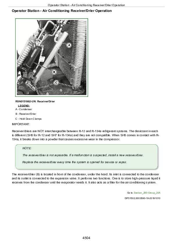
Remove and Install Receiver-Drier
Remove and Install the Evaporator and Expansion Valve
Arrangement of Condensation Water Drain Hoses
Remove and Install Thermostat Switch
Adjust Thermostat Switch Bowden Cable
Remove and Install the High/Low Pressure Switch
Group 15: Heating System
Heating System (Summary of References)
Remove and Install Radiator
Remove and Install Fan Motors
Remove and Install Fan Motor Resistors
Remove and Install Heater Valve
Adjust Heater Valve Bowden Cable
Remove and Install Control Console for Ventilation System
Change Air Hoses in Ventilation System
Group 20: Seats
Seats – Summary of References
Seats – Specifications
Seats – Special Tools, Summary of References
Remove the Operator’s Seat
Install the Operator’s Seat
Comfort Seat MSG83
Air Comfort Seat MSG95 – Remove and Install the Compressor
Air Comfort Seat MSG95 – Remove and Install the Air Spring
Air Comfort Seat MSG95, Check and Adjust the Height-Adjustment Bowden Cables and Lever
Air Comfort Seat MSG95, Remove and Install the Height-Adjustment Bowden Cables and Lever
Air Comfort Seat MSG95 – Adjust the Level Control (Micro-Switch, Vent Valve)
Air Comfort Seat MSG95 – Remove and Install the Level Control with Height Stop
Air Comfort Seat MSG95 – Remove and Install the Compressed-Air Hoses (Hoses with Quick-Coupling System)
Air Comfort Seat MSG95 – Remove and Install the Compressed-Air Hoses (Hose System with Clamps)
Air Comfort Seat MSG95 – Remove and Install the Air Tank with Additional Capacity
Passenger Seat, Exploded View
Group 25: Operator’s Cab
Operator’s Cab – Summary of References
Cab Mounting Torques
Remove and Install Windshield
Remove and Install Rear Window
Remove and Install Sun Roof
Installing Door Lock
Remove and Install Cab Door
Remove Trim Panels from Switch Console
Install Trim Panels from Shift Console
Remove Inner Roof Trim
Install Inner Roof Trim
Group 30: Parts for Electronic Hitch Control
Electronic Hitch Control (Summary of References)
Disconnecting Electrical Circuit
Service Information
Replace Hitch Control Operation Unit
Section 99: Special Tools
Group 05: Special Tools (Dealer-Fabricated)
DFLX1 – Adapter Strut
DFLX6 – Bushing
DFLX8 – Thrust Pieces
DFLX38 – Turning Device
Group 10: Special Tools (Available as Spare Part)
AR52361 – Socket
D01019AA – Manually-Operated Hydraulic Pump
D01042AA – Load-Positioning Sling
D01045AA – Bushing, Bearing and Seal Driver Set
FKM10002 or JT05470 – Pressure Test Kit
FKM10409 – Battery Tester
FKM10427 – Crimping Pliers
FKM10444 – Leak Detector
FKM10455 – Extraction Tool
FKM10456 – Extraction Tool
FKM10457 – Extraction Tool
FKM10470 – Pressure Measuring System (Stage 1)
FKM10471 – Pressure Measuring System (Stage 2)
FKM10461 – Wiring Harness Repair Kit
FKM10469 – Crimping Pliers
FKM10472 – Flow Measurement System
FKM10472-4 – Temperature Sensor
FKM10482 – Pressure Test Kit
JDE83 – Flywheel Turning Tool
JDG19 – Special Mounting Brackets
JDG23 – Lifting Sling
JDG359 – Electrical Repair Tool Kit
JDG360 – DEUTSCH Crimping Pliers
JDG361 – Extraction Tool
JDG362 – Extraction Tool
JDG749 – 1,30 m (52 in.) Torque wrench extension
JDG750 – Swivel Socket
JDG765 – Bushing Installer
JDG772 – Planetary Installation Tool
JDG775 – Seal Installer
JDG776 – Extraction Tool
JDG777 – Extraction Tool
JDG785 – Extraction Tool
JDG1655A – Suspension Device for PowrQuad Transmission
KJD10557 – Cab Tilting Device
KJD10561 – Bracket for Lift Post (5020, 5R and 5M)
KJD10562 – Tilt Joint Kit (5020, 5R and 5M)
KJD10565 – Storing system for tilting device KJD10557
KJD10570 – Safety Equipment (Air-Conditioning Service)
KJD10571 – Protective Cover for Air-Conditioning Service Unit
KJD10572 – Standard Flushing Kit (Air-Conditioning Service)
KJD10573 – UV Contrast Agent (Air-Conditioning Service)
KJD10574 – Hose Extensions (2.5 m) (Air-Conditioning Service)
KJD10575 – PAG Oil (Air-Conditioning Service)
KJD10576UV – Lamp and Safety Goggles (Air-Conditioning Service)
KJD10577 – Filter/Receiver-Drier Cartridge for Air-Conditioning Service Unit
JDG10974EU – Air-Conditioning Service Unit
JDH43A – Tester for Pressure-Relief Valves
JT02043 – Support Stand
JT02044 – Support Stand
JT02153 – Clamp-On Current Probe
JT03248 – Fitting
JT05472 – Pressure Gauge
JT05723 – Medium-Duty Rear Tractor Splitting Stand
JT05724 – Medium-Duty Front Tractor Splitting Stand
JT05725 – Universal Support Stand
JT05791A – Multimeter
JT07115 – Pressure Test Kit
JT07211 – Support Stand
KJD10128 – Fitting
KJD10194 – Pressure Test Kit
KJD10227 – Special Tool
KJD10278 – Special Tool
KJD10283 – Supplementary Kit
KJD10292 – Diagnostic Harness
KJD10293 – Disconnecting Tool
KJD10501 – Disconnecting Tools (Kit)
KJD10352 – Restriction Fitting
KJD10388 – Assembly fixture
KJD10426 – Special Tool
KJD10495 – Hose Connector
KJD10529 – Cutting Tool
KJD10530 – Pliers
KJD10559 – Support Stand for Front Axle and Final Drives
KJD10560 – Adapter for TLS Front Axle (Used in Conjunction with Support Stand KJD10559)
KML10005 – Spring Compressor
R83489 – Adapter available as spare part
RE200689 – Performance Monitor
RE37996 – Adjusting Tool

John Deere Tractor 5080R(N), 5090R(N), 5100R(N) Repair Service Manual (TM401819)


INSTANT DOWNLOAD


Posted on

John Deere 5080R, 5090R, 5100R, 5080RN, 5090RN and 5100RN Operator’s Manual – OMAL200158


INSTANT DOWNLOAD


Complete Operator’s Manual Traktors 5080R, 5090R, 5100R, 5080RN, 5090RN and 5100RN, with all the technical information to maintain and operate.

omal200158 – 5080R, 5090R, 5100R, 5080RN, 5090RN and 5100RN Operator’s Manual.pdf
omal200157 – 5080R, 5090R, 5100R, 5080RN, 5090RN and 5100RN (German).pdf
omal200159 – 5080R, 5090R, 5100R, 5080RN, 5090RN and 5100RN (French).pdf
omal200161 – 5080R, 5090R, 5100R, 5080RN, 5090RN and 5100RN -: (Europeisk utgåva) (Swedish).pdf
omal200162 – 5080R, 5090R, 5100R, 5080RN, 5090RN and 5100RN -: (Europeisk versjon) (Norwegian).pdf
omal200163 – 5080R, 5090R, 5100R, 5080RN, 5090RN and 5100RN -: (Europæisk version) (Danish).pdf
omal200164 – 5080R, 5090R, 5100R, 5080RN, 5090RN and 5100RN -: (Euroopan versio) (Finnish).pdf
omal200165 – 5080R, 5090R, 5100R, 5080RN, 5090RN and 5100RN -: (Versione europea) (Italian).pdf
omal200167 – 5080R, 5090R, 5100R, 5080RN, 5090RN and 5100RN -: (Europese versie) (Dutch).pdf
omal200189 – 5080R, 5090R, 5100R, 5080RN, 5090RN and 5100RN -: (Edição europeia) (Portuguese).pdf
omal200190 – 5080R, 5090R, 5100R, 5080RN, 5090RN and 5100RN -: (Ευρωπαϊκή έκδοση) Greek.pdf
omal200191 – 5080R, 5090R, 5100R, 5080RN, 5090RN and 5100RN -: (Europsko izdanje) Croatian.pdf
omal200192 – 5080R, 5090R, 5100R, 5080RN, 5090RN and 5100RN -: (Evropské vydání) Czech.pdf
omal200193 – 5080R, 5090R, 5100R, 5080RN, 5090RN és 5100RN traktorok -: (Európai változat) Hungarian.pdf
omal200194 – 5080R, 5090R, 5100R, 5080RN, 5090RN and 5100RN -: (Eвропейска версия) Bulgarian.pdf
omal200195 – 5080R, 5090R, 5100R, 5080RN, 5090RN and 5100RN -: (Wersja europejska) Polish.pdf
omal200196 – 5080R, 5090R, 5100R, 5080RN, 5090RN and 5100RN -: (Evropska izvedba) Slovenian.pdf
omal200197 – 5080R, 5090R, 5100R, 5080RN, 5090RN and 5100RN -: (Leidinys Europai) Lithuanian.pdf
omal200198 – 5080R, 5090R, 5100R, 5080RN, 5090RN and 5100RN -: (Avrupa Sürümü) Turkish.pdf
omal200199 – 5080R, 5090R, 5100R, 5080RN, 5090RN and 5100RN -: (Evrópsk útgáfa) Icelandic.pdf
omal200200 – 5080R, 5090R, 5100R, 5080RN, 5090RN and 5100RN -: (Eiropas versija) Latvian-lettish.pdf
omal200203 – 5080R, 5090R, 5100R, 5080RN, 5090RN and 5100RN -: (Ediţie europeană) Romanian.pdf
omal200204 – 5080R, 5090R, 5100R, 5080RN, 5090RN and 5100RN -: (Euroopa versioon) Estonian.pdf
omal200205 – 5080R, 5090R, 5100R, 5080RN, 5090RN and 5100RN -: (Európske vydanie) Slovak.pdf
omal200206 – 5080R, 5090R, 5100R, 5080RN, 5090RN and 5100RN -: (Verzija za Evropu) Serbian.pdf
omal200207 – Руководство оператора 5080R, 5090R, 5100R, 5080RN, 5090RN и 5100RN Russian.pdf

Total Pages: 456 pages
File Format: PDF/EPUB/MOBI/AZW (PC/Mac/Android/Kindle/iPhone/iPad; bookmarked, ToC, Searchable, Printable)
Language: English

Table of Contents
Foreword
Section 00: Identification Views
Identification Views
Section 05: Safety
Replace Safety Signs
Recognize Safety Information
anderstand Signal Words
Follow Safety Instructions
Prepare for Emergencies
Wear Protective Clothing
Protect Against Noise
Handle Fuel Safely—Avoid Fires
Fire Prevention
Use Foldable ROPS and Seat Belt Properly
Stay Clear of Rotating Drivelines
Use Steps and Handholds Correctly
Read Operator Manuals for ISOBUS Implements
Use Seat Belt Properly
Vibration
Operating the Tractor Safely
Avoid Backover Accidents
Limited Use in Forestry Operation
Operating the Loader Tractor Safely
Keep Riders Off Machine
Passenger Seat
Use Safety Lights and Devices
Towing Trailers/Implements Safely (Mass)
Use Caution On Slopes and Uneven Terrain
Freeing a Mired Machine
Avoid Contact with Agricultural Chemicals
Handle Agricultural Chemicals Safely
Handling Batteries Safely
Avoid Heating Near Pressurized Fluid Lines
Remove Paint Before Welding or Heating
Welding Near Electronic Control Units
Handle Electronic Components and Brackets Safely
Practice Safe Maintenance
Avoid Hot Exhaust
Work In Ventilated Area
Support Machine Properly
Prevent Machine Runaway
Park Machine Safely
Transport Tractor Safely
Service Cooling System Safely
Service Accumulator Systems Safely
Service Tires Safely
Service Front-Wheel Drive Tractor Safely
Tightening Wheel Retaining Bolts/Nuts
Avoid High-Pressure Fluids
Do Not Open High-Pressure Fuel System
Store Attachments Safely
Dispose of Waste Properly
Section 10: Safety Decals
Pictorial Safety Signs
Operator’s Manual
Riders on Tractors with Passenger Seat
Hitch Remote Control
Compressed Air Tank for Trailer Brake
Pick-Up Hitch
Section 15: Controls and Instruments
Vehicle Controls
Auxiliary and Park Brake System
PTO Controls
Reduction Gear Controls
Attachment Controls
Heater and Air-Conditioning Controls
Operate Fan Reverser
Indicator Lights and Displays
Performance Monitor
Data Entry Mode
Operating Touch Pad Switches
Operation and Calibration
Wheel Slip (3)
Vehicle Speed (6)
Service (8)
Backlight Brightness—Cab Displays
Adjusting Backlight—Performance Monitor
Software Update
Section 20: Lights
Lights
H4 Farm Headlights
Light Switch
Operating the Hazard Warning Light Switch
Switches for Turn Signal Lights and Horn
Worklight Switches
Seven-Terminal Trailer Socket
Section 25: Operator’s Cab
Cab Classification According to EN 15695-1 (for Application of Crop Protection Chemicals and Liquid Fertilizer)
Roll-Over Protective Structure
Seat Belt
Avoid Contact with Agricultural Chemicals
Clean Vehicle of Hazardous Pesticides
Comfort Seat
Super Comfort Seat
Instructional Seat
Open Windows
Opening Sun Roof (Option)
Wiper and Washer System
Fan and Air Louvers
Heater
Air-Conditioning System
Storage Rack
Additional Storage Area
Dome Light
Adjusting the Steering Wheel
Beacon Light
Installing the Monitor
Sockets
Multiple Power Outlet Socket Strip
Service ADVISOR SERVICE ADVISOR is a trademark of Deere & Company Socket
Emergency Exits
Section 30: Break-in Period
After the First 4 and 8 Hours of Operation
Within the First 100 Hours of Operation
After the First 100 Hours of Operation
Section 35: Prestarting Checks
Prestarting Checks
Comply with Operator’s Manuals of Implement Manufacturers
Section 40: Operating the Engine
Important Information Regarding the Engine
Start the Engine
Cold-Weather Starting Aids
Electrical Starting Aid
Coolant Heater
Starting the Engine With a Slave Battery
Starting with a Replacement Battery
Fuel Preheater
Engines with Turbocharger
Engine Protection
Towing the Tractor
Parking the Tractor
Stopping the Engine
Battery Cut-Off Switch (If Equipped)
Chock Block (If Equipped)
Section 45: Operating the Tractor
Reduce Fuel Consumption
Select Correct Groand Travel Speed
Groand Speeds
Shift the PowrQuad Plus Transmission
Shift the AutoQuad Plus Transmission
Engage the Reduction Gear
Engage the Front-Wheel Drive
Engage the Differential Lock
Hydraulic Foot Brakes
Hydraulic Trailer Brakes
Air Brakes on Trailer
Section 50: Hitch
Maximum Lifting Force
Hitch Control
Hitch Fender Control
Height Adjustment
Transporting Mounted Implements
Hitch Dampening
Adjusting Rate of Implement Drop
Depth Adjustment
Load/Depth Adjustment
1 Depth Control
2-4 Mixed Control
5 Load Control
Float Position
Direct Actuation
Three-point hitch
Flat Steel Draft Links
Telescopic Draft Links
Quick-Coupling (Hook-Type) Draft Links
Attach Three-Point Hitch Mounted and Drawn Implements
Leveling the Implement
Center Link
Hydraulic Center Link (Option)
Center Link Positions
Lift Links
Adjust for Vertical Float
Stabilizer Bar (If Equipped)
Stabilizing System (If Equipped)
Section 51: HMS — Headland Management System
HMS – Headland Management System (If Equipped) — Basic Principles
Headland Management System (HMS) — Details
Section 55: PTO
PTO Guard
Operating Instructions
PTO Options
PTO Speeds
Front PTO
Operating PTOs
Operating the PTO by Fender Control
Reversing Rear PTO Shafts
Select Rear PTO Speed
Attaching PTO-Driven Equipment
Section 60: Ballast
Selecting Ballast
Ballasting Rear Wheels
Measuring Rear Wheel Slip
Installing Weights on Flanged Axle
Filling Tires with Liquid Ballast
Draining the Tires
Pre-Assembling the Pick-Up Weight
Attaching the Pick-Up Weight
With Weight in Three-Point Hitch
Installing Front Weights
Section 65: Wheel Tread, Tires
Change Wheels Safely
Adjust Front-Wheel Tread
Tighten Front Wheel Attaching Nuts
Check Front Wheel Toe-In
Adjusting Toe-In
Adjusting the Fixed Fenders
Adjusting the Pivoting Fenders
Adjusting Rear-Wheel Tread
Tread Widths
Tire Pressures
Service Tires Safely
Tire Combinations
Section 70: Additional Equipment
Selective Control Valves
Levers for Selective Control Valves
Multi-Function Lever (Mechanical)
Mechanical Multi-Function Lever with Front-Loader Dampening
Raise Rate
Couplers
Hose Unions
Maximum Permissible Oil Withdrawal
Front Three-Point Hitch
Adjustable Drawbar
Proper Use of Drawbar
Adjustment of Drawbar
Front Jaw Hitch
Height-Adjustable Trailer Hitch
Remote Control (If Equipped)
Pick-Up Hitch
Front Loader Installation – Front Loader Brackets
Section 75: Transport
Transporting the Tractor
Towing the Tractor
Driving on Public Roads
Section 80: Fuel, Lubricants, Hydraulic Oil and Coolant
Diesel Fuel
Lubricity of Diesel Fuel
Handling and Storing Diesel Fuel
Bio-Diesel Fuel
Diesel Engine Break-In Oil
Diesel Engine Oil and Filter Service Intervals
Transmission and Hydraulic Oil
Front-Wheel Drive Axle Oil
Grease
Oil Filters
Lubricant Storage
Mixing of Lubricants
Alternative and Synthetic Lubricants
Heavy Duty Diesel Engine Coolant
John Deere COOL-GARD™ II Coolant Extender
Operating in Warm Temperature Climates
Drain Intervals for Diesel Engine Coolant
Additional Information About Diesel Engine Coolants and John Deere LIQUID COOLANT CONDITIONER
Testing Diesel Engine Coolant
Oilscan™ and CoolScan™
Section 85: Lubrication and Periodic Service
Using High Pressure Washers
Lubrication and Periodic Service
General Instructions Regarding the Condition of the Tractor
Open the Hood
Access to Battery
Access to Fuses
Jack Up the Tractor – Lifting Points
Safe Maintenance and Cleaning
Important Instructions Regarding Alternator
After the First 100 Hours
As Required
Check/Replace Hydraulic Hoses
Periodic Service
Other Service Jobs
Note Regarding the Service Interval for Engine Coolant
Service (Daily / Every 10, Every 250, Every 500, Every 750 Hours)
Service (Annually, Every 1000, Every 1500, Every 2000 Hours)
Service (Every 4500 and Every 6000 Hours)
Section 90: Service / Daily or Every 10 Hours
Check Engine Oil Level
Check Fuel Filter
Checking and Draining the Compressed Air Trailer Brake System
Clean the Dust Unloading Valve
Rocker Arm Cover Ventilation
Coolant Level
Checking on Lights
Other Service Jobs
Section 95: Service / Every 250 Hours
Servicing the Fuel Tank
Check Transmission/Hydraulic System Oil Level
Checking Electrolyte Level of Battery
Lubricating the Front Axle and U.j. Shaft
Checking Oil Level in MFWD Axle Housing
Checking Oil Level in MFWD Final Drives
Check brakes
Check the Park Brake
Check Park Lock (If Equipped)
Lubricate the Three-Point Hitch
Lubricate Front Three-Point Hitch
Lubricate the Pivoting Fenders
Lubricate Trailer Hitch
Lubricating the Pick-Up Hitch
Check the Neutral Start Circuit
Check PTO Safety Switch
Check Torques
Check the Manually-Operated Hitch for Wear
Check the Manually-Operated Hitch for Wear (Italy and Spain Only)
Check Remote Controlled Hitch for Wear
Trailer Hitch, Check the Guide Rails
Check the Drawbar for Wear
Check Tow-Hook on Pick-Up Hitch for Wear
Section 100: Service / Every 500 Hours
Change Engine Oil
Changing Engine Oil Filter
Change the Fuel Filters
Lubricating Rear Axle Bearings
Air Intake Hoses
Checking the Engine Groand Connection
Check the Cab Groand Connection
Check Engine Drive Belt for Wear
Section 105: Service / Every 750 Hours
Replacing Transmission/Hydraulic System Filter Elements
Check the Cab Mounting Screws
Section 110: Service / Once a Year
Checking the Seat Belt (If Equipped)
Check Engine Coolant
Check/Replace Hydraulic Hoses
Section 115: Service / Every 1500 Hours or 2 Years
Changing Oil in Front-Wheel Drive Axle
Change Oil In Front-Wheel Drive Axle Housing
Change Oil in Front-Wheel Drive Final Drives
Change Transmission/Hydraulic Oil
Change Oil at Front PTO (If Equipped)
Section 120: Service / Every 6000 Hours or 6 Years
Note Regarding the Service Interval for Engine Coolant
Change Coolant
Section 125: Service / As Required
Engine Air Cleaner
Clean the Primary Filter Element
Clean a Dusty Element
Secondary (Safety) Element
Installation
Clean the Cab Air Filter
Keep Radiator Screen Clean
Check Coolant Level
Check Fuel Filter
Bleeding the Fuel System
Lubricate All Lubricating Points
Operator’s Seat
Prevent Battery Explosions
Battery – Checking Specific Gravity
Starter Motor
Fuses and Relays in the Engine Compartment
Fuses and Relays (Engine Compartment)
Starting Motor Relay (Engine Compartment)
Fuse on Tractors with a Battery Cut-Off Switch
Fuses F01PLB to F04PLB and Relays K05PLB to K06PLB (Engine Compartment)
Fuses and Relays in the Cab
Fuses and Relays (Cab)
Relays K01 (Cab)
Fuses F02 (Cab)
Fuses F03 (Cab)
Fuses F04 (Cab)
Fuses F05 (Cab)
Relays K06 (Cab)
Relays/Diodes K07 (Cab)
Relays K08 (Cab)
Section 130: Troubleshooting
Hydraulic System
Engine
Electrical System
Section 135: Diagnostic Trouble Codes
What the Diagnostic Trouble Codes Mean
Customization
General Operation and Entering the Program Mode
Accessing Addresses and Diagnostic Trouble Codes
BCU Control Unit
BIF Control Unit
ECU Control Unit
EPC Control Unit
PrF Control Unit
Section 140: Storage
Storage for Long Period
Removing Tractor from Storage
Section 145: Specifications
Engine
PTO Power Output
Transmission
Hydraulic System
Loads and Weights
How to Calculate Maximum Permissible Download on Trailer Hitch
Towed Mass
How to Calculate Permissible Mass
Electrical System
Capacities
Maximum Lifting Force
Soand Level
Permissible Front Axle Load in Relation to Tires (Normal Operation)
Permissible Front Axle Load in Relation to Tires (Operation with Front Loader)
Permissible Rear Axle Load in Relation to Tires
Vibration
Safety Note Regarding the Subsequent Installation of Electrical and Electronic Appliances and/or Components
EC Declaration of Conformity
Section 150: Serial Numbers
Type Plates
Product Identification Number
Engine Serial Number
Transmission Serial Number
Front-Wheel Drive Axle Serial Number

John Deere 5080R, 5090R, 5100R, 5080RN, 5090RN and 5100RN Operator’s Manual – OMAL200158


INSTANT DOWNLOAD


Posted on

John Deere PowerTech E 4.5L & 6.8L Diesel Engines Component Technical Manual (CTM502)


INSTANT DOWNLOAD


Component Technical Manual with Electrical Wiring Diagrams for John Deere PowerTech E 4.5L & 6.8L Diesel Engines, with all the shop information to maintain, diagnostic, repair, refurbish/rebuild like professional mechanics.

Component Technical Manual for John Deere PowerTech E 4.5L & 6.8L Diesel Engines workshop service & repair manual includes:
* Numbered table of contents easy to use so that you can find the information you need fast.
* Detailed sub-steps expand on repair procedure information
* Numbered instructions guide you through every repair procedure step by step.
* Troubleshooting and electrical service procedures are combined with detailed wiring diagrams for ease of use.
* Notes, cautions and warnings throughout each chapter pinpoint critical information.
* Bold figure number help you quickly match illustrations with instructions.
* Detailed illustrations, drawings and photos guide you through every procedure.
* Enlarged inset helps you identify and examine parts in detail.

ctm503 – Dizelski motor 4045-6068 – ECU Nivel 16 – (Edición mundial) Tehnični priročnik za komponente.pdf
ctm504 – Moteur diesel 4045-6068 — Contrôleur ECU de niveau 16 – (Édition globale) Manuel technique des composants.pdf
ctm505 – Dieselmotor 4045-6068 – ECU (Stufe 16) – (Weltweite Ausgabe) Technisches Komponentenhandbuch.pdf
ctm506 – Motore diesel 4045–6068 – Livello ECU 16 – Manuale tecnico dei componenti (edizione universale).pdf
ctm507 – Motor Diesel 4045–6068 — ECU Nível 16 – (Edição Mundial) Manual técnico de Componentes.pdf
ctm511 – Дизельные двигатели 4045, 6068 — Блок управления двигателем (ECU), уровень 16 — (Глобальная версия) Техническое руководство по компонентам.pdf
ctm513 – 4045-6068 柴油发动机 — 16 级 ECU – (世界通用机型 ) 维修手册.pdf
ctm517 – Silnik Diesla 4045–6068 – Poziom ECU 16 – (Wydanie ogólnoświatowe) Podręcznik techniczny komponentów.pdf
ctm608 – 4045-6068 Dizel Motor — Seviye 16 ECU (Dünya Çapında Sürüm) Bileşen Teknik Kılavuzu.pdf
CTM502 (09NOV12) (ENGLISH) – John Deere PowerTech E 4.5L & 6.8L Diesel Engines (Level 16 Electronic Fuel System with Denso HPCR) Component Technical Manual.pdf
CTM502 – John Deere Level 16 Electronic Fuel System with Denso HPCR Component Technical Manual.pdf

PRODUCT DETAILS:
Total Pages: 1,501 pages
File Format: PDF (Internal Links, Bookmarked, Table of Contents, Searchable, Printable, high quality)
Language: English
ctm502 – 4045-6068 Diesel Engine — Level 16 ECU -: (Worldwide Edition) Component Technical Manual – Table of Contents
Foreword
Trademarks
Section 01: General
Group 000: Safety
Avoid Heating Near Pressurized Fluid Lines
Avoid High-Pressure Fluids
Avoid Hot Exhaust
Avoid Static Electricity Risk When Refueling
Construct Dealer-Made Tools Safely
Decommissioning — Proper Recycling and Disposal of Fluids and Components
Follow Safety Instructions
Handle Agricultural Chemicals Safely
Handle Fluids Safely—Avoid Fires
Handling Batteries Safely
Illuminate Work Area Safely
Install All Guards
Live With Safety
Park Machine Safely
Practice Safe Maintenance
Precautions for Welding
Prepare for Emergencies
Prevent Acid Burns
Prevent Battery Explosions
Prevent Machine Runaway
Protect Against High Pressure Spray
Protect Against Noise
Recognize Safety Information
Remove Paint Before Welding or Heating
Replace Safety Signs
Service Cooling System Safely
Service Machines Safely
Stay Clear of Rotating Drivelines
Support Machine Properly
Understand Signal Words
Use Proper Lifting Equipment
Use Proper Tools
Use Steps and Handholds Correctly
Wait Before Opening High-Pressure Fuel System
Wear Protective Clothing
Work in Clean Area
Work In Ventilated Area
Group 001: Engine Identification
Engine Serial Number Plate Information
OEM Engine Option Code Label
Information Relative to Emissions Regulations
Emissions Control System Certification Label
Group 002: Fuels, Lubricants, and Coolant
Diesel Fuel
Diesel Fuel Additive Products
BioDiesel Fuel
Minimizing the Effect of Cold Weather on Diesel Engines
Handling and Storing Diesel Fuel
Lubricity of Diesel Fuel
Testing Diesel Fuel
Engine Oil and Filter Service Intervals
Diesel Engine Oil — Tier 3 and Stage III
Diesel Engine Break-In Oil — Non-Emissions Certified and Certified Tier 1, Tier 2, Tier 3, Stage I, Stage II, and Stage III
Oil Filters
Grease
Alternative and Synthetic Lubricants
Lubricant Storage
Mixing of Lubricants
Diesel Engine Coolant (engine with wet sleeve cylinder liners)
Supplemental Coolant Additives
Operating in Warm Temperature Climates
Additional Information About Diesel Engine Coolants and John Deere LIQUID COOLANT CONDITIONER
Diesel Engine Coolant
Testing Diesel Engine Coolant
Drain Intervals for Diesel Engine Coolant
Section 02: Repair and Adjustments
Group 090: Electronic Fuel System Repair and Adjustments
Fuel System – General Information
Relieve Fuel System Pressure
Fuel System Components
Replace Fuel Filter Element (Primary or Final)
Remove and Install Fuel Filter Base (Primary and Final)
Remove Fuel Transfer Pump
Install Fuel Transfer Pump
Remove and Install High-Pressure Fuel Pump
Remove and Install Suction Control Valve
Remove and Install High-Pressure Common Rail
Remove and Install Flow Dampers
Remove and Install Pressure Limiter
Remove and Install Fuel Injection Wire Harness Assembly
Injector Identification Tag Information
Remove Electronic Injector (EI)
Clean Electronic Injector (EI) Bore
Clean Electronic Injector (EI) Orifice
Clean Electronic Injector (EI) Body
Inspect Electronic Injector (EI) Body
Install Electronic Injector (EI)
Remove and Install Fuel Leak-Off Line
Clean Electronic injectors (In Engine)
Group 110: Electronic Engine Control Repair and Adjustment
Engine Control Unit (ECU) Maintenance
Welding
High Pressure Washing
Remove and Install Engine Control Unit (ECU) on Engine (Optional Equipment)
Remove and Install Adaptation Parts for Engine Control Unit (ECU) Mounted on Engine (Optional Equipment)
Remove and Install Engine Coolant Temperature (ECT) Sensor
Remove and Install Fuel Temperature Sensor
Remove and Install Manifold Air Temperature (MAT) Sensor
Remove and Install Oil Pressure Sensor
Remove and Install Fuel Rail Pressure Sensor
Remove and Install Fuel Transfer Pump Pressure Sensor
Remove and Install Crankshaft Position Sensor
Remove and Install Pump Position Sensor
Remove and Install Water-In-Fuel (WIF) Sensor
Install Wiring Harness for Engine Mount ECU
Install Wiring Harness for Remote ECU
Connectors
Connector Repair
Installation of Repair Wire Assembly (RWA)
Repair WEATHERPACK Connector
Repair Cinch FlexBox Connector
Repair Metri-Pack Connectors (Push Type)
Repair DT Series DEUTSCH Connectors
Repair HD Series DEUTSCH Connectors
Section 03: Theory Of Operation
Group 130: Electronic Fuel System Operation
About This Group
Fuel System Operation
Prefilter Operation
Mechanical Fuel Transfer Pump Operation
Electric Fuel Transfer Pump Operation
Final Fuel Filter Operation
Type 1 High Pressure Fuel Pump Operation
High Pressure Common Rail (HPCR) Operation
Electronic Injector (EI) Operation
Group 135: Air and Exhaust Operation
Air Intake and Exhaust System Operation
Air Cleaner Operation
Turbocharger Operation
How the Turbocharger Is Lubricated
Group 140: Electronic Control System Operation
About This Group
Electronic Control System Terminology
Electronic Control Unit (ECU) System Operation
Component Location Diagram 1
Component Location Diagram 2
Component Location Diagram 3
Component Location Diagram 4
Component Location Diagram 5
Component Location Diagram 6
Component Location Diagram 7
Component Location Diagram 8
Component Location Diagram 9
Component Location Diagram 10
Component Location Diagram 11
Component Location Diagram 12
Component Location Diagram 13
Component Location Diagram 14
Component Location Diagram 15
Component Location Diagram 16
Engine Control Unit (ECU)
Controller Area Network (CAN)
Pilot Injection Operation
Monitoring Engine Parameters
Measuring Temperature
Engine Control Unit (ECU) Temperature Sensor
Engine Coolant Temperature (ECT) Sensor
Fuel Temperature Sensor
Intake Manifold Air Temperature (MAT)
Turbo Turbine Inlet Temperature
Measuring Pressure
Barometric Air Pressure (BAP) Sensor
Fuel Rail Pressure Sensor
Fuel Transfer Pump Pressure Sensor
Manifold Air Pressure (MAP) Sensor
Oil Pressure Sensor
Dual Fuel Rail Pressure Sensor (Redundant ECU Applications)
Measuring Speed
Crank Position Sensor
Pump Position Sensor
Throttle Descriptions
CAN Throttle
Pulse-Width-Modulated (PWM) Throttle
Analog Throttle
Digital Multi-State Throttle
Dual-State Throttle
Tri-State Throttle
Ramp Throttle
Throttle Adjustments
Throttle Offsets
Self-Calibration
Combination Throttle
Marine Throttle
Engine Derate and Shutdown Protection
Electronic Injector (EI) Wiring Harness Connector
Intake Air Heater Operation
Torque Curve Selection
Governor Droop Mode Selection
Suction Control Valve
Water in Fuel (WIF) Sensor
Cruise Control Operation
Power Supply #1
Power Supply #2
Power Supply #3
Section 04: Diagnostics
Group 150: Observable Diagnostics and Tests
About This Group
E1 – Engine Cranks/Won’t Start
E2 – Engine Misfires/Runs Irregularly
E3 – Engine Does Not Develop Full Power
E4 – Engine Emits Excessive White Exhaust
E5 – Engine Emits Excessive Black or Gray Exhaust
E6 – Engine Will Not Crank
E7 – Engine Idles Poorly
E8 – Abnormal Engine Noise
E9 – Primary Analog Throttle Does Not Respond
E10 – Secondary Analog Throttle Does Not Respond
F1 – Low-Pressure Fuel Supply System Test
F2 – High-Pressure Fuel Supply System Test
F3 – Excessive Fuel Consumption
F4 – Fuel in Oil
F5 – Excessive Fuel Filter Replacement
D1 – ECU Does Not Communicate with Service ADVISOR
D2 – ECU Does Not Communicate with Diagnostic Gauge or Gauge Displays CAN Bus Error
D5 – ECU Does Not Program With Service ADVISOR
A1 – Intake Air Heater Check
Bleed the Fuel System
Charge Air Cooler Test
Charge Air System
Check and Adjust High-Pressure Fuel Pump Static Timing
Check Engine Oil Pressure
Check for Restricted Fuel Leak-off Line
Check Fuel Supply Quality
Cylinder Leak-Down Test
Cooling System Test
EGR Cooler Test
Engine Coolant Temperature Below Normal
Excessive Engine Crankcase Pressure (Blow-By) Test
Test for Air in Fuel
Thermostat — Testing
Group 160: Trouble Code Diagnostics and Tests
About This Group
Change Fan Speed Table
Communication Error Test Instructions
Connecting to Service ADVISOR
Control Unit Information and Overview Test
Cylinder Cutout Test Instructions
Cylinder Electronic Compression Test Instructions
Cylinder Misfire Test Instructions
Diagnostic Gauge Active DTC Viewing Instructions
Diagnostic Gauge Data Parameters Viewing Instructions
Diagnostic Gauge Stored DTC Clearing Instructions
Diagnostic Gauge Stored DTC Viewing Instructions
Diagnostic Test Box — Using
Diagnostic Trouble Code Designations
Diagnostic Trouble Code List
Digital Multimeter — Using
Electrical Circuit Concepts
Electrical Noise — Possible Causes
Electronic Injector — Calibration Information
Engine Hours — Updating Instructions
Failure Mode Indicator Designations
Fuel Rail Cap and Plug Kit
Harness Diagnostic Mode Test
Interactive Tests and Calibration Results — Printing, Exporting, or Saving Instruction
Intermittent DTC Diagnostics
Internal Data Monitor — Instructions
Keep Electronic Control Unit Connectors Clean
Load Profile Information Test — Instructions
Engine Control Unit (ECU) — Level Identification
Engine Control Unit (ECU) — Donating this Engine’s ECU to be Used Elsewhere
Engine Control Unit (ECU) — Replacing Current ECU with Another ECU
Engine Control Unit (ECU) — Replacing Current ECU with Another ECU — Cannot Communicate with Current ECU
Engine Control Unit (ECU) — Reprogramming Current ECU
Engine Control Unit (ECU) — Reprogramming Instructions
Problem Not Found Procedure
Service Advisor Data Parameter Description
Short to Voltage Procedure
Snapshot Instructions
Software and Hardware Verification
Terminal Test
Trim Options Information
Verification Procedure
Wiggle Test
000028.03 – Digital Throttle Signal Out of Range High
000028.04 – Digital Throttle Signal Out of Range Low
000028.14 – Digital Throttle Inhibited
000029.03 – Secondary Analog Throttle Signal Out of Range High
000029.04 – Secondary Analog Throttle Signal Out of Range Low
000029.14 – Secondary Analog Throttle Inhibited
000084.31 – ECU Calculated Vehicle Speed and CAN Vehicle Speed Mismatch
000091.03 – Primary Analog Throttle Signal Out of Range High
000091.04 – Primary Analog Throttle Signal Out of Range Low
000091.09 – Primary Analog Throttle Signal Erratic
000091.14 – Primary Analog Throttle Inhibited
000094.03 – Low-Pressure Fuel Signal Out of Range High
000094.04 – Low-Pressure Fuel Signal Out of Range Low
000094.17 – Low Pressure Fuel Signal Slightly Low
000094.18 – Low-Pressure Fuel Signal Moderately Low
000097.03 – Water-In-Fuel Signal Out of Range High
000097.04 – Water-In-Fuel Signal Out of Range Low
000097.16 – Water-In-Fuel Detected
000100.01 – Engine Oil Pressure Signal Extremely Low
000100.04 – Engine Oil Pressure Signal Out of Range Low
000100.18 – Engine Oil Pressure Signal Moderately Low
000100.31 – Engine Oil Pressure Detected with Engine Stopped
000105.00 – Manifold Air Temperature Signal Extremely High
000105.03 – Manifold Air Temperature Signal Out of Range High
000105.04 – Manifold Air Temperature Signal Out of Range Low
000105.15 – Manifold Air Temperature Signal Slightly High
000105.16 – Manifold Air Temperature Signal Moderately High
000107.00 – Air Filter Restriction Switch Activated
000107.31 – Air Filter Restriction Switch Activated
000108.02 – Barometric Air Pressure Signal Invalid
000110.00 – Coolant Temperature Signal Extremely High
000110.03 – Coolant Temperature Signal Out of Range High
000110.04 – Coolant Temperature Signal Out of Range Low
000110.15 – Coolant Temperature Signal Slightly High
000110.16 – Coolant Temperature Signal Moderately High
000110.17 – Engine Coolant Temperature Signal Slightly Low
000111.01 – Coolant Level Extremely Low
000157.03 – Fuel Rail Pressure Signal Out of Range High
000157.04 – Fuel Rail Pressure Signal Out of Range Low
000157.10 – Fuel Rail Pressure Loss Detected
000157.17 – Fuel Rail Pressure Not Developed
000158.17 – ECU Power Down Error
000160.02 – Vehicle Speed Signal Invalid
000171.03 – Ambient Air Temperature Out of Range High
000171.04 – Ambient Air Temperature Out of Range Low
000174.00 – Fuel Temperature Signal Extremely High
000174.03 – Fuel Temperature Signal Out of Range High
000174.04 – Fuel Temperature Signal Out of Range Low
000174.16 – Fuel Temperature Signal Moderately High
000189.00 – Engine Speed Derate Condition Exists
000190.00 – Engine Speed Extremely High
000190.16 – Engine Speed Moderately High
000237.02 – VIN Security Data Invalid
000237.13 – VIN Option Code Security Data Conflict
000237.31 – VIN Security Data Missing
000569.03 – Rear Axle Differential Lock Signal Out of Range High
000569.04 – Rear Axle Differential Lock Signal Out of Range Low
000611.03 – Injector Shorted to Voltage Source
000611.04 – Injector Shorted to Ground
000627.01 – All Injector Circuits Have High Resistance
000627.18 – Injector Power Supply Voltage Out of Range Low
000629.12 – ECU EEPROM Error
000629.13 – ECU Boot Block Error
000636.02 – Camshaft Position Signal Invalid
000636.05 – Camshaft Position Circuit Has High Resistance
000636.06 – Camshaft Position Circuit Has Low Resistance
000636.08 – Camshaft Position Signal Missing
000636.10 – Camshaft Position Signal Rate of Change Abnormal
000637.02 – Crankshaft Position Signal Invalid
000637.05 – Crankshaft Position Circuit Has High Resistance
000637.06 – Crankshaft Position Circuit Has Low Resistance
000637.07 – Crankshaft and Camshaft Position Signals Out of Sync
000637.08 – Crankshaft Position Signal Missing
000637.10 – Crankshaft Position Signal Rate of Change Abnormal
000640.31 – External Derate Commanded
000647.05 – Engine Fan Drive Circuit Has High Resistance
000647.31 – Engine Fan Drive Manual Purge Switch Active Too Long
000651.02 – Injector #1 Part Number Invalid
000651.05 – Injector #1 Circuit Has High Resistance
000651.06 – Injector #1 Circuit Has Low Resistance
000651.13 – Injector #1 Calibration Fault
000652.02 – Injector #2 Part Number Invalid
000652.05 – Injector #2 Circuit Has High Resistance
000652.06 – Injector #2 Circuit Has Low Resistance
000652.13 – Injector #2 Calibration Fault
000653.02 – Injector #3 Part Number Invalid
000653.05 – Injector #3 Circuit Has High Resistance
000653.06 – Injector #3 Circuit Has Low Resistance
000653.13 – Injector #3 Calibration Fault
000654.02 – Injector #4 Part Number Invalid
000654.05 – Injector #4 Circuit Has High Resistance
000654.06 – Injector #4 Circuit Has Low Resistance
000654.13 – Injector #4 Calibration Fault
000655.02 – Injector #5 Part Number Invalid
000655.05 – Injector #5 Circuit Has High Resistance
000655.06 – Injector #5 Circuit Has Low Resistance
000655.13 – Injector #5 Calibration Fault
000656.02 – Injector #6 Part # Data Invalid
000656.05 – Injector #6 Circuit Has High Resistance
000656.06 – Injector #6 Circuit Has Low Resistance
000656.13 – Injector #6 Calibration Fault
000676.03 – Cold Start Aid Signal Received When Not Expected
000676.05 – Cold Start Aid Circuit Has High Resistance
000898.09 – Engine Speed CAN Message Invalid
000970.31 – External Shutdown Switch Activated
000971.31 – External Derate Switch Activated
001069.31 – Tire Size Invalid
001075.05 – Low Pressure Fuel Pump Circuit Has High Resistance
001075.06 – Low Pressure Fuel Pump Circuit Has Low Resistance
001109.31 – Approaching Engine Protection Shutdown
001110.31 – Engine Protection Shutdown Active
001136.00 – ECU Temperature Signal Extremely High
001136.02 – ECU Temperature Signal Invalid
001136.16 – ECU Temperature Signal Moderately High
001321.05 – Starter Solenoid Lockout Relay Drive Circuit Has High Resistance
001321.06 – Starter Solenoid Lockout Relay Drive Circuit Has Low Resistance
001321.30 – Starter Solenoid Lockout Relay Drive Circuit Fault
001347.03 – Suction Control Valve Signal Out of Range High
001347.05 – Suction Control Valve Circuit Has High Resistance
001347.07 – Fuel Rail Pressure Actual to Desired Mismatch
001349.02 – Fuel Rail Pressure Signals Mismatch
001349.03 – Redundant Fuel Rail Pressure Signal Out of Range High
001349.04 – Redundant Fuel Rail Pressure Signal Out of Range Low
001569.31 – Engine in Power Derate Condition
001638.09 – Hydraulic Oil Temperature Erratic
001639.01 – Fan Speed Signal Extremely Low
001639.16 – Fan Speed Signal Moderately High
002000.13 – Incorrect ECU for Application
002003.09 – No CAN Message Received From Source Address 3
002004.09 – No CAN Message Received From Source Address 4
002023.09 – No CAN Message From Source Address 23
002033.09 – No CAN Message Received From Source Address 33
002033.14 – Incorrect CAN Message Received From Source Address 33
002033.19 – Synchronizing Problem with Source Address 33
002057.09 – No CAN Message Received From Source Address 57
002071.09 – No CAN Message From Source Address 71
003509.03 – Sensor Supply #1 Voltage Out of Range High
003509.04 – Sensor Supply #1 Voltage Out of Range Low
003510.03 – Sensor Supply #2 Voltage Out of Range High
003510.04 – Sensor Supply #2 Voltage Out of Range Low
003511.03 – Sensor Supply #3 Voltage Out of Range High
003511.04 – Sensor Supply #3 Voltage Out of Range Low
523792.04 – EPGDS LTC Pump Signal Out of Range Low
524099.11 – EPGDS LTC Pump Blockage
524037.02 – MFWD Switch Circuit Fault
524223.03 – Rear Axle Differential Lock Circuit Fault
524225.31 – Engine Start Protection Bypass Detected
524235.03 – MFWD Solenoid Signal Out of Range High
524235.04 – MFWD Solenoid Signal Out of Range Low
Section 05: Tools and Other Materials
Group 170: Special Tools
75240
D05104ST
D17030BR
DFRG11
J-35616-20
JDE83
JDG145
JDG359
JDG360
JDG361
JDG362
JDG363
JDG364
JDG776
JDG777
JDG782A
JDG783
JDG785
JDG820
JDG839
JDG865
JDG1560
JDG1571
JDG1652A
JDG1725
JDG1727
JDG1744
JDG1869
JDG10234
JDG10244
JDG10273
JDG10273P1
JDG10407
JDG10408
JDG10415
JDG10416
JDG10446
JDG10447
JDG10452
JDG10453
JDG10456
JDG10457
JDG10460
JDG10461
JDG10466
JDG10467
JDG10539A
JDG10576
JDG10760
JDG10854
JDG11072
JDG11100A
JDG11233
JDG11263
JDG11264
JDG11269
JDG11409
JT03513C
JT05412
JT05470
JT05536
JT07253
JT07306
Group 180: Lubricants, Sealants, and Other Materials
Other Materials (Consumables)
Section 06: Specifications
Group 200: Repair Specifications
Unified Inch Bolt and Cap Screw Torque Values
Metric Bolt and Cap Screw Torque Values
Electronic Fuel System Repair and Adjustment Specifications
Electronic Engine Control Repair and Adjustment Specifications
Group 210: Diagnostic Specifications
Fuel System Diagnostic Specifications
Application Specifications
OEM Engines – Derate Specifications
OEM Engines – Air Heater Specifications
4.5L 12V ECU Wiring Diagram 1
4.5L 12V ECU Wiring Diagram 2
4.5L 12V ECU Wiring Diagram 3
4.5L 12V ECU Wiring Diagram 4
4.5L 12V ECU Wiring Diagram 5
4.5L 12V ECU Wiring Diagram 6
4.5L 12V ECU Wiring Diagram 7
4.5L 24V ECU Wiring Diagram 1
4.5L 24V ECU Wiring Diagram 2
4.5L 24V ECU Wiring Diagram 3
4.5L 24V ECU Wiring Diagram 4
4.5L 24V ECU Wiring Diagram 5
4.5L 24V ECU Wiring Diagram 6
4.5L 24V ECU Wiring Diagram 7
6.8L 12V ECU Wiring Diagram 1
6.8L 12V ECU Wiring Diagram 2
6.8L 12V ECU Wiring Diagram 3
6.8L 12V ECU Wiring Diagram 4
6.8L 12V ECU Wiring Diagram 5
6.8L 12V ECU Wiring Diagram 6
6.8L 12V ECU Wiring Diagram 7
6.8L 24V ECU Wiring Diagram 1
6.8L 24V ECU Wiring Diagram 2
6.8L 24V ECU Wiring Diagram 3
6.8L 24V ECU Wiring Diagram 4
6.8L 24V ECU Wiring Diagram 5
6.8L 24V ECU Wiring Diagram 6
6.8L 24V ECU Wiring Diagram 7
OEM Instrument Panel / Engine Start Components Electrical Wiring Diagram
OEM Instrument Panel / Engine Start Components Electrical Wiring Diagram – Continued
4.5L Wire Splice Location Diagrams
6.8L Wire Splice Location Diagrams
Oil Temperature Switch Option
Redundant ECU Option 4.5L Wiring Diagrams
Redundant ECU Option 6.8L Wiring Diagrams
Redundant ECU Option Wire Splice Location Diagrams


INSTANT DOWNLOAD


Posted on

John Deere 00.16, 20.09, 20.09C, 20.11, 20.16, G20.16 and G20.09 Front Wheel Drive Axles Technical Service Manual (CTM4870)


INSTANT DOWNLOAD


Complete service repair manual for John Deere 00.16, 20.09, 20.09C, 20.11, 20.16, G20.16 and G20.09 Front Wheel Drive Axles, with all the technical information to maintain, diagnose, repair, and rebuild like professional mechanics.

John Deere 00.16, 20.09, 20.09C, 20.11, 20.16, G20.16 and G20.09 Front Wheel Drive Axles workshop service repair manual includes:
* Numbered table of contents easy to use so that you can find the information you need fast.
* Detailed sub-steps expand on repair procedure information
* Numbered instructions guide you through every repair procedure step by step.
* Troubleshooting and electrical service procedures are combined with detailed wiring diagrams for ease of use.
* Notes, cautions and warnings throughout each chapter pinpoint critical information.
* Bold figure number help you quickly match illustrations with instructions.
* Detailed illustrations, drawings and photos guide you through every procedure.
* Enlarged inset helps you identify and examine parts in detail.

ctm4870 – 00.16, 20.09, 20.09C, 20.11, 20.16, G20.16 and G20.09 Front Wheel Drive Axles Component Technical Manual (EN).pdf
ctm8227 – Mosty napędowe na przednie koła00.16, 20.09, 20.09C, 20_11, 20_16, G20_16 i G20_09 Podręcznik techniczny komponentów.pdf
ctm8224 – Predné hnacie nápravy00.16, 20.09, 20.09C, 20.11, 20.16, G20.16 a G20.09 – (európska verzia) Technická príručka komponentov.pdf
ctm8223 – Přední hnací nápravy00.16, 20.09, 20.09C, 20.11, 20.16, G20.16 a G20.09 Technická příručka komponent.pdf
ctm8222 – Forhjulsdrevne aksler 00.16, 20.09, 20.09C, 20.11, 20.16, G20.16 og G20.09.pdf
ctm4877 – MFWD-axlarna00.16, 20.09, 20.09C, 20.11, 20.16, G20.16 och G20.09 Komponent teknisk manual.pdf
ctm4876 – Forhjulstrækaksler 00.16, 20.09, 20.09C, 20.11, 20.16, G20.16 og G20.09 Teknisk manual for komponenter (NOR).pdf
ctm4875 – Etuakselit 00.16, 20.09, 20.09C, 20.11, 20.16, G20.16 ja G20.09 Komponentin tekninen käsikirja.pdf
ctm4874 – Assen voorwielaandrijving 00.16, 20.09, 20.09C, 20.11, 20.16, G20.16 en G20.09 Component Technische Handleiding.pdf
ctm4873 – Manuale tecnico dei componenti degli assi G20.16 e G20.09FWD 00.16, 20.09, 20.09C, 20.11, 20.16.pdf
ctm4871 – Ponts avant 00.16, 20.09, 20.09C, 20.11, 20.16, G20.16 et G20.09 Manuel technique des composants.pdf
ctm4834 – Technisches Komponentenhandbuch für Vorderradantriebsachsen 00.16, 20.09, 20.09C, 20.11, 20.16, G20.16 und G20.09.pdf
ctm8148 – tehnični priročnik za sprednje pogonske osi 00.16, 20.09, 20.09c, 20.11, 20.16, g20.16 in g20.09.pdf

PRODUCT DETAILS:
Total Pages: 324 pages
File Format: PDF (Internal Links, Bookmarked, Table of Contents, Searchable, Printable, high quality)
Language: English etc.

TABLE OF CONTENTS…1
Section 00: Front-Wheel Drive Axles…13
Group 00: Safety Information…13
Recognize Safety Information…19
“Important” – Information…20
“Note” – Information…21
Prevent Machine Runaway…22
Handle Fluids Safely—Avoid Fires…23
Prepare for Emergencies…24
Avoid High-Pressure Fluids…25
Remove Paint Before Welding or Heating…26
Avoid Heating Near Pressurized Fluid Lines…27
Work In Ventilated Area…28
Wear Protective Clothing…29
Practice Safe Maintenance…30
Park Machine Safely…31
Use Proper Lifting Equipment…32
Construct Dealer-Made Tools Safely…33
Support Machine Properly…34
Work in Clean Area…35
Illuminate Work Area Safely…36
Service Machines Safely…37
Use Proper Tools…38
Service Tires Safely…39
Service Front-Wheel Drive Tractor Safely…40
Dispose of Waste Properly…41
Live With Safety…42
Retighten Wheel Nuts…43
Mixing of Lubricants…44
Lubricant Storage…45
Group 01: General Repair Information…13
General Safety and Repair Information…47
Front-Wheel-Drive Axles – Torques for Bolts and Nuts…48
Special tool kit KJD10415 for 00.16 axle model…51
Group 05: Steering Cylinder and Tie Rods…14
Repair Specifications…181
Steering Cylinder and Tie Rods — Exploded View (00.16 Axle)…54
Remove Tie Rods (00.16 Axle)…55
Remove Steering Cylinder (00.16 Axle)…57
Install Steering Cylinder (00.16 Axle)…58
Install Tie Rods (00.16 Axle)…61
Steering Cylinder and Tie Rods — Exploded View (20.11 and 20.16 Axles)…63
Remove Tie Rods (20.11 and 20.16 Axles)…64
Remove Steering Cylinder (20.11 and 20.16 Axles)…66
Install Steering Cylinder (20.11 and 20.16 Axles)…68
Install Tie Rods (20.11 and 20.16 Axles)…70
Steering Cylinder and Tie Rods — Exploded View (20.09 Axle)…72
Steering Cylinder and Tie Rods – Exploded View (G20.09 and G20.16 Axles)…74
Remove Tie Rods (20.09, G20.09 and G20.16 Axles)…77
Remove Steering Cylinder (20.09, G20.09 and G20.16 Axles)…79
Install Steering Cylinder (20.09, G20.09 and G20.16 Axles)…82
Install Tie Rods (20.09, G20.09 and G20.16 Axles)…85
Checking and Adjusting Tread (Basic Adjustment)…88
Checking and Adjusting Steering Angle…91
Checking and Adjusting Steering Angle (G20.09 and G20.16 Axles)…92
Group 10: Planetary Drive and Wheel Hub…14
Special Tools…254
Repair Specifications…181
Planetary Drive – Exploded View (00.16, 20.09, 20.11, 20.16, G20.16 and G20.09 Axles)…99
Remove Planetary Drive (00.16, 20.09, 20.11, 20.16, G20.16 and G20.09 Axles)…102
Install Planetary Drive (00.16, 20.09, 20.11, 20.16, G20.16 and G20.09 Axles)…107
Planetary Drive and Wheel Hub — Exploded View (20.09C Axle)…112
Remove Planetary Drive and Wheel Hub (20.09C Axle)…113
Install Planetary Drive and Wheel Hub (20.09C Axle)…116
Planetary Drive – Fill With Oil…120
Wheel Hub — Exploded View (00.16, 20.09, 20.11, 20.16, G20.16 and G20.09 Axles)…121
Remove Wheel Hub (00.16, 20.09, 20.11, 20.16, G20.16 and G20.09 Axles)…122
Repair Wheel Hub (00.16, 20.09, 20.11, 20.16, G20.16 and G20.09 Axles)…123
Install Wheel Hub (00.16, 20.09, 20.11, 20.16, G20.16 and G20.09 Axles)…126
Group 15: Knuckle Housing and Drive Shafts…15
Special Tools…254
Specifications…137
Knuckle Housing and Drive Shaft — Exploded View (00.16, 20.09, 20.11 and 20.16 Axles)…138
Knuckle Housing and Drive Shaft – Exploded View (G20.09, 20.16 Applies to newer versions. and G20.16 Axles)…15
Remove Knuckle Housing (00.16, 20.09, 20.11, 20.16, G20.16 and G20.09 Axles)…141
Repair Knuckle Housing and King Pin (00.16, 20.09, 20.11 and 20.16 Axles)…143
Repair Knuckle Housing and King Pin (G20.09, 20.16 Applies to newer versions. and G20.16 Axles)…15
Install Knuckle Housing (00.16, 20.09, 20.11, 20.16, G20.16 and G20.09 Axles)…151
Remove Drive Shaft (00.16, 20.09, 20.11, 20.16, G20.16 and G20.09 Axles)…153
Install Drive Shaft (00.16, 20.09, 20.11, 20.16, G20.16 and G20.09 Axles)…155
Knuckle Housing and Drive Shaft — Exploded View (20.09C Axle)…158
Remove Knuckle Housing (20.09C Axle)…160
Repair Knuckle Housing and King Pin (20.09C Axle)…162
Install Knuckle Housing (20.09C Axle)…165
Remove Drive Shafts (20.09C Axle)…167
Install Drive Shafts (20.09C Axle)…169
Group 20: Axle Housing and Differential…15
Special Tools…254
Repair Specifications…181
Axle Housing and Differential Carrier – Exploded View (00.16, G20.16 and G20.09 Axles)…183
Axle Housing and Differential Carrier — Exploded View (20.09, 20.09C, 20.11 and 20.16 Axles)…185
Pinion Shaft — Exploded View (00.16 Axle)…186
Pinion Shaft — Exploded View (20.09, 20.09C, 20.11 and 20.16 Axles)…187
Pinion Shaft – Exploded View (G20.09 and G20.16 Axles)…188
Remove Pinion Shaft (00.16, G20.16 and G20.09 Axles)…190
Install and Adjust Pinion Shaft (00.16, G20.16 and G20.09 Axles)…192
Remove Pinion Shaft (20.09, 20.09C, 20.11 and 20.16 Axles)…199
Install and Adjust Pinion Shaft (20.09, 20.09C, 20.11 and 20.16 Axles)…201
Differential – Exploded View (G20.09 Axle)…208
Remove Differential (00.16, G20.16 and G20.09 Axles)…209
Repair Differential (00.16 Axle)…212
Repair Differential (G20.09 and G20.16 Axles)…218
Install Differential (00.16, G20.16 and G20.09 Axles)…225
Remove Differential (20.09, 20.09C, 20.11 and 20.16 Axles)…235
Repair Differential (20.09, 20.09C, 20.11 and 20.16 Axles)…238
Install Differential (20.09, 20.09C, 20.11 and 20.16 axles)…242
Axle Housing — Fill With Oil…250
Group 25: Axle Suspension…16
Special Tools…254
Axle Suspension — Exploded View (00.16 Axle)…257
Remove Axle Suspension (00.16 Axle)…258
Install Axle Suspension (00.16 Axle)…263
Axle Suspension — Exploded View (20.11 and 20.16 Axles)…269
Remove Axle Suspension (20.11 and 20.16 Axles)…270
Install Axle Suspension (20.11 and 20.16 Axles)…273
Axle Suspension — Exploded View (20.09 Axle)…276
Remove Axle Suspension (20.09 Axle)…277
Install Axle Suspension (20.09 Axle)…278
Axle Suspension – Exploded View (G20.09 and G20.16 Axle)…279
Remove Axle Suspension (G20.09 and G20.16 Axles)…280
Install Axle Suspension (G20.09 and G20.16 Axles)…282
Axle Suspension – Exploded View (G20.16 For submodels CA635497 and CA635198 Axle)…16
Remove Axle Suspension (G20.16 For submodels CA635497 and CA635198 Axle)…16
Install Axle Suspension (G20.16 For submodels CA635497 and CA635198 Axle)…16
Group 200: Description and Theory of Operation…16
Front Wheel Drive Axles — Summary of References…295
Description of Front Wheel Drive…296
Layout of Front Axle…297
Operation of Differential…299
Operation of Self-Locking Differential…302
Operation of Planetary Drive…303
Positive Front Wheel Lead Check…304
Operational Check of Front Wheel Drive Axle…305
Group 212: Observable Symptoms…17
Noises when Driving with Front-Wheel Drive Engaged…17
Unusual Vibrations when Driving with Front-Wheel Drive Engaged…17

John Deere 00.16, 20.09, 20.09C, 20.11, 20.16, G20.16 and G20.09 Front Wheel Drive Axles Technical Service Manual (CTM4870)


INSTANT DOWNLOAD


Posted on

John Deere 5090R, 5100R, 5115R, 5115RH, and 5125R (FT4_Stage IIIB) Tractors Diagnosis and Tests Service Technical Manual (tm143419)


INSTANT DOWNLOAD


Complete Diagnosis & Tests Technical Manual with electrical wiring diagrams for John Deere 5090R, 5100R, 5115R, 5115RH, and 5125R (FT4_Stage IIIB) Tractors, with workshop information to maintain, diagnose, and rebuild like professional mechanics.

John Deere 5090R, 5100R, 5115R, 5115RH, and 5125R (FT4_Stage IIIB) Tractors workshop Diagnosis & Tests technical manual includes:
* Numbered table of contents easy to use so that you can find the information you need fast.
* Detailed sub-steps expand on repair procedure information
* Numbered instructions guide you through every repair procedure step by step.
* Troubleshooting and electrical service procedures are combined with detailed wiring diagrams for ease of use.
* Notes, cautions and warnings throughout each chapter pinpoint critical information.
* Bold figure number help you quickly match illustrations with instructions.
* Detailed illustrations, drawings and photos guide you through every procedure.
* Enlarged inset helps you identify and examine parts in detail.

tm143482 – Tehnični priročnik za diagnostiko traktorjev 5090R, 5100R, 5115R in 5125R (FT4_ stopnja IIIB) Tehnični priročnik (Slovenian).pdf
tm143480 – 5090R, 5100R, 5115R ve 5125R (FT4_Aşama IIIB) Traktörleri Arıza Tanı Teknik El Kitabı Teknik Kılavuz (TR).pdf
tm143478 – Tekniske diagnosehåndbøker for traktorene 5090R, 5100R, 5115R og 5125R (FT4_trinn IIIB) Teknisk håndbok (NOR).pdf
tm143458 – Manual tehnic de diagnosticare pentru tractoare 5090R, 5100R, 5115R, şi 5125R (FT4_Stadiul IIIB) Manual tehnic (RO).pdf
tm143439 – Manuale tecnico per la diagnosi dei trattori 5090R, 5100R, 5115R, e 5125R (FT4_Stage IIIB) Manuale Tecnico (IT).pdf
tm143429 – Traktoren 5090R, 5100R, 5115R und 5125R (FT4_Stufe IIIB) – Technisches Diagnosehandbuch (DE).pdf
tm143428 – Manuel technique de diagnostic des tracteurs 5090R, 5100R, 5115R et 5125R (FT4_Phase IIIB) Manuel technique (FR).pdf
tm143419 – 5090R, 5100R, 5115R, 5115RH, and 5125R (FT4_Stage IIIB) Tractors Testing & Diagnostics Technical Manual (EN).pdf

PRODUCT DETAILS:
Total Pages: 4,571 pages
File Format: PDF/EPUB/MOBI/AZW (PC/Mac/Android/Kindle/iPhone/iPad; bookmarked, ToC, Searchable, Printable)
Language: English

TABLE OF CONTENTS
TABLE OF CONTENTS….1
Section 210: General Information….49
Group 05: Safety….49
Work In Ventilated Area….53
Recognize Safety Information….54
Avoid Backover Accidents….55
Prevent Machine Runaway….56
Avoid Contact with Agricultural Chemicals….57
Clean Vehicle of Hazardous Pesticides….59
Use a Safety Chain….60
Work in Clean Area….61
Decommissioning — Proper Recycling and Disposal of Fluids and Components….62
Avoid Harmful Asbestos Dust….63
Use Electronic Display Properly….64
Avoid Hot Exhaust….65
Clean Exhaust Filter Safely….66
Exhaust Filter Cleaning….69
Handle Fuel Safely—Avoid Fires….70
Prepare for Emergencies….71
In Case of Fire….72
Handle Fluids Safely—Avoid Fires….73
Avoid High-Pressure Fluids….74
Use Foldable ROPS and Seat Belt Properly….75
Avoid Static Electricity Risk When Refueling….76
Install All Guards….78
Use Proper Lifting Equipment….79
Illuminate Work Area Safely….80
Live With Safety….81
Service Machines Safely….82
Support Machine Properly….83
Protect Against Noise….84
Remove Paint Before Welding or Heating….85
Park Machine Safely….86
Stay Clear of Rotating Drivelines….93
Follow Safety Instructions….89
Use Proper Tools….90
Service Tires Safely….91
Keep ROPS Installed Properly….92
Stay Clear of Rotating Drivelines….93
Construct Dealer-Made Tools Safely….94
Practice Safe Maintenance….95
Understand Signal Words….97
Replace Safety Signs….98
Protect Against High Pressure Spray….99
Store Attachments Safely….100
Avoid Heating Near Pressurized Fluid Lines….101
Wear Protective Clothing….102
Precautions for Welding….103
Service Accumulator Systems Safely….105
Handling Batteries Safely….106
Handle Agricultural Chemicals Safely….108
Service Cooling System Safely….110
Wait Before Opening High-Pressure Fuel System….111
Service Front-Wheel Drive Tractor Safely….112
Use Steps and Handholds Correctly….113
Handle Electronic Components and Brackets Safely….114
Transport Tractor Safely….115
Deliver Safely….116
Group 10: General References….50
General Information – Summary of References….119
Regions and Country Versions….120
Trademarks….122
Glossary of Terms….123
Group 15: How to Use This Manual….127
How to Use This Manual….127
Information Available in Sections, Groups and Subgroups….128
General Troubleshooting Information….129
Systematic Diagnostic Approach Overview….131
Group 20: Machine and Technical References….51
Product Identification Number….137
Features and Accessories….139
Metric Bolt and Screw Torque Values….145
Unified Inch Bolt and Screw Torque Values….147
Section 211: Diagnostic Trouble Codes….149
Group ABV: ABV Code Diagnosis….149
ABV 000000.00-999999.99 – ABV Diagnostic Trouble Codes….149
Group AIC: AIC Code Diagnostics….149
AIC 000000.00-999999.99 – AIC Diagnostic Trouble Codes….149
Group CCU: CCU Code Diagnostics….149
CCU 000000.00-999999.99 – CCU Diagnostic Trouble Codes….149
Group CLC: CLC Code Diagnostics….149
CLC 000000.00-999999.99 – CLC Diagnostic Trouble Codes….149
Group CSA: CSA Code Diagnostics….149
CSA 000000.00-999999.99 – CSA Diagnostic Trouble Codes….149
Group CSM: CSM Code Diagnostics….149
CSM 000000.00-999999.99 – CSM Diagnostic Trouble Codes….149
Group ECU: ECU Code Diagnostics….149
ECU 000000.00-999999.99 – ECU (FT4/Stage IV) Diagnostic Trouble Codes….149
ECU 000000.00-999999.99 – ECU (IT4/Stage IIIB) Diagnostic Trouble Codes….149
Group EIC: EIC Code Diagnostics….149
EIC 000000.00-999999.99 – EIC Diagnostic Trouble Codes….149
Group FCC: FCC Code Diagnostics….149
FCC 000000.00-999999.99 – FCC Diagnostic Trouble Codes….149
Group GM2: GM2 Code Diagnostics….149
GM2 000000.00-999999.99 – GM2 Diagnostic Trouble Codes….149
Group HCC: HCC Code Diagnostics….149
HCC 000000.00-999999.99 – HCC Diagnostic Trouble Codes….149
Group HV1: HV1 Code Diagnostics….149
HV1 000000.00-999999.99 – HV1 Diagnostic Trouble Codes….149
Group JDL: JDL Code Diagnostics….149
JDL 000000.00-999999.99 – JDL Diagnostic Trouble Codes….149
Group MFC: MFC Code Diagnostics….149
MFC 000000.00-999999.99 – MFC Diagnostic Trouble Codes….149
Group OIC: OIC Code Diagnostics….149
OIC 000000.00-999999.99 – OIC Diagnostic Trouble Codes….149
Group PDU: PDU Code Diagnostics….150
PDU 000000.00-999999.99 – PDU Diagnostic Trouble Codes….150
Group PTF: PTF Code Diagnostics….150
PTF 000000.00-999999.99 – PTF Diagnostic Trouble Codes….150
Group PTU: PTU Code Diagnostics….150
PTU 000000.00-999999.99 – PTU Diagnostic Trouble Codes….150
Group RPT: RPT Code Diagnostics….150
RPT 000000.00-999999.99 – RPT Diagnostic Trouble Codes….150
Group SB1: SB1 Code Diagnostics….150
SB1 000000.00-999999.99 – SB1 Diagnostic Trouble Codes….150
Group SB2: SB2 Code Diagnostics….150
SB2 000000.00-999999.99 – SB2 Diagnostic Trouble Codes….150
Group SB3: SB3 Code Diagnostics….150
SB3 000000.00-999999.99 – SB3 Diagnostic Trouble Codes….150
Group SBK: SBK Code Diagnostics….150
SBK 000000.00-999999.99 – SBK Diagnostic Trouble Codes….150
Group SBL: SBL Code Diagnostics….150
SBL 000000.00-999999.99 – SBL Diagnostic Trouble Codes….150
Group SBM: SBM Code Diagnostics….150
SBM 000000.00-999999.99 – SBM Diagnostic Trouble Codes….150
Group SCC: SCC Code Diagnostics….150
SCC 000000.00-999999.99 – SCC Diagnostic Trouble Codes….150
Group SFA: SFA Code Diagnostics….150
SFA 1-99 – SFA Diagnostic Trouble Codes….150
Group SMB: SMB Code Diagnostics….150
SMB 000000.00-999999.99 – SMB Diagnostic Trouble Codes….150
Group TEC: TEC Code Diagnostics….150
TEC 000000.00-999999.99 – TEC Diagnostic Trouble Codes….150
Group TIU: TIU Code Diagnostics….150
TIU 000000.00-999999.99 – TIU Diagnostic Trouble Codes….150
Group VLC: VLC Code Diagnostics….150
VLC 000000.00-999999.99 – VLC Diagnostic Trouble Codes….150
Group VTV: VTV Code Diagnostics….151
VTV 000000.00-999999.99 – VTV Diagnostic Trouble Codes….151
Group XMC: XMC Code Diagnostics….151
XMC 000000.00-999999.99 – XMC Diagnostic Trouble Codes….151
Group XSC: XSC Code Diagnostics….151
XSC 000000.00-999999.99 – XSC Diagnostic Trouble Codes….151
Section 212: Observable Symptoms and System Diagnostics….590
Group 05: General References….590
Observable Symptoms and System Diagnostics – Summary of References….597
Group 20: Engine Diagnostics….590
Engine System Problems….590
Group 30: Fuel, Air Intake, Exhaust, and Cooling Diagnostics….590
Fuel, Air Intake, and Exhaust System Problems….590
Group 40: Electrical Diagnostics….590
Charging System Problems….590
Starting System Problems….590
Power Outlet Problems….590
Door Switch and Dome Lamp Problems….590
ISOBUS Problems….590
Trailer Connector and Junction Block Problems….590
Fuel Gauge Problems….590
Fuel Gauge System Diagnosis….590
Group 45: Electronic Control Unit Diagnostics….590
CAN System Diagnosis….590
Implement CAN System Diagnosis….590
Hitch/SCV CAN System Diagnosis….590
Codes After Adding / Removing Control Units….590
Control Unit Problems….590
Control Unit Programming Failed….590
Control Unit System Diagnosis….590
Programming Multiple Control Units….590
5 Volt Sensor Supply Circuit Problems….590
Armrest Control Unit Problems (AIC, CSM, and MFC)….590
Cab Control Unit Problems (CLC, EIC, FCC, OIC, TIU, AIC, CSM, and MFC)….590
Rear Control Unit Problems (CCU, CSA, HCC, PTU, RPT, SCC, and VLC)….590
Primary Display Unit Problems (PDU, and VTV)….590
Engine Control Unit Problems (ECU)….590
Front PTO Control Unit Problems (PTF)….590
Steering, Braking, and Backup Control Unit Problems (XMC and XSC)….591
Suspended Front Axle Control Unit Problems (SFA)….591
Tractor Equipment Communication Control Unit Problems (TEI, TEC, and GM2)….591
Rear EH SCVs Control Unit Problems (SB1, SB2, and SB3)….591
Mid-Mount EH SCVs Control Unit Problems (SBK, SBL, SBM)….591
EH Hitch Control Unit Problems (HV1)….591
AutoTrac Basic Control Unit Problems (ABV)….591
Group 50: Transmission Diagnostics….591
PPST Transmission Problems….591
PPST Transmission System Diagnosis….591
Group 51: Drive Systems Diagnostics….591
Differential Lock Problems….591
Differential Lock System Diagnosis….591
Front PTO Problems….591
Front PTO System Diagnosis….591
Rear PTO Problems….591
Rear PTO System Diagnosis….591
MFWD Problems….591
MFWD System Diagnosis….591
Suspended Front Axle Problems….591
Suspended Front Axle System Diagnosis….591
Group 60: Brakes Diagnostics….591
Brake Problems….591
Brake System Diagnosis (R4)….591
Brake System Diagnosis (R2)….591
Secondary Brake Problems….591
Secondary Brake System Diagnosis….591
Hydraulic Trailer Brake Problems….591
Hydraulic Trailer Brake System Diagnosis….591
Air Trailer Brake Problems….591
Air Trailer Brake System Diagnosis….591
Group 61: Steering Diagnostics….591
OC Steering Problems….591
OC Steering System Diagnosis….592
CC Steering and AutoTrac Problems….592
CC Steering and AutoTrac System Diagnosis….592
Group 70: Hydraulic Diagnostics – Open Center System….592
OC Hydraulics – Implement Hydraulics Problems….592
OC Hydraulics – Implement Hydraulics System Diagnosis….592
OC Hydraulics – Electrohydraulic Hitch Problems….592
OC Hydraulics – Electrohydraulic Hitch System Diagnosis….592
OC Hydraulics – Mid-Mount SCV Problems….592
OC Hydraulics – Mid-Mount SCV System Diagnosis….592
OC Hydraulics – Rear SCV Problems….592
OC Hydraulics – Rear SCV System Diagnosis….592
Group 71: Hydraulic Diagnostics – Closed Center System….592
CC Hydraulics – System Problems….592
CC Hydraulics – System Diagnosis….592
CC Hydraulics – Rear and Mid-Mount SCV Problems….592
CC Hydraulics – Rear and Mid-Mount SCV System Diagnosis….592
CC Hydraulics – Electrohydraulic Hitch Problems….592
CC Hydraulics – Electrohydraulic Hitch System Diagnosis….592
Group 90: Cab/Operator Station Diagnostics….592
Heating, Ventilation, and Air Conditioning Problems….592
Heating, Ventilation, and Air Conditioning System Diagnosis….592
Radio Problems….592
Seat Problems….592
Wiper Problems….592
Section 220: Engine….774
Group 05: General References….774
Engine – Summary of References….776
Engine – General Information….777
Group 10: Calibrations, Preliminary and Operational Checks….774
Engine – Calibrations, Preliminary and Operational Checks….779
Group 20: Theory of Operation….774
Engine – Final Tier 4/Stage IV Operation….781
Engine – Interim Tier 4/Stage IIIB Operation….782
Group 30: Schematics….774
Engine – Schematics….784
Group 40: Components and Connectors….774
Engine – Final Tier 4/Stage IV Overview….787
Engine – Interim Tier 4/Stage IIIB Overview….789
Group 50: Tests and Adjustments….774
Engine – Test Procedures and Adjustments….792
Engine – Performance Testing….793
Engine – Performance Variables….796
Section 230: Fuel, Air, and Cooling….798
Group 05: General References….798
Fuel, Air, and Cooling – Summary of References….800
Fuel, Air, and Cooling – General Information….801
Group 10: Calibrations, Preliminary and Operational Checks….798
Fuel, Air, and Cooling – Calibrations, Preliminary and Operational Checks….803
Group 20: Theory of Operation….798
Fuel, Air, and Cooling – Air Intake Operation….806
Fuel, Air, and Cooling – Cooling Operation….808
Fuel, Air, and Cooling – Fuel Operation (Final Tier 4/Stage IV)….811
Fuel, Air, and Cooling – Fuel Operation (Interim Tier 4/Stage IIIB)….813
Fuel, Air, and Cooling – Fuel Cooler Operation….815
Fuel, Air, and Cooling – DEF Tank Header Operation….816
Fuel, Air, and Cooling – Exhaust Aftertreatment Operation (Final Tier 4/Stage IV)….818
Fuel, Air, and Cooling – Exhaust Aftertreatment Operation (Interim Tier 4/Stage IIIB)….821
Group 30: Schematics….798
Fuel, Air, and Cooling – Schematics….823
Group 40: Components and Connectors….798
Fuel, Air, and Cooling – Component Overview….825
Group 50: Tests and Adjustments….798
Fuel, Air, and Cooling – Tests and Adjustments….827
Section 240A: Electrical – General and Theory of Operation….828
Group 05: General References….828
Electrical General and Theory of Operation – Summary of References….830
How to Use Electrical Information….831
How to Use Electrical Theory of Operation….832
Group 20A: Starting, Charging, and Neutral Start Theory of Operation….828
Starting, Charging, and Neutral Start Operation….840
Group 20B: Heating, Ventilation, and Air Conditioning Theory of Operation….828
Heating, Ventilation, and Air Conditioning Electrical Operation….849
Section 240B: Electrical – Schematics….853
Group 05: General References….853
Electrical Schematics – Summary of References….858
How to Use Electrical Schematics Information….861
Reading Wiring Schematics and Diagrams….862
Wiring Diagram Information….866
Electrical Schematic Symbols….868
Group SE01: Key Switch, Starter, Alternator, and Power Outlets….853
Key Switch, Starter, Alternator, and Power Outlets Schematic (SE01)….874
Group SE02: Front PTO….853
Front PTO Schematic (SE02)….878
Group SE03: Front Axle Suspension….853
Front Axle Suspension Schematic (SE03)….881
Group SE04: Cab Control Unit….853
Cab Control Unit Schematic (SE04.1)….886
Cab Control Unit Schematic (SE04.2)….889
Group SE05: Front Implement Connector….853
Front Implement Connector Schematic (SE05)….894
Group SE06: Mid-Mount SCV Grapple….853
Mid-Mount SCV Grapple Schematic (SE06)….897
Group SE07: Heating, Ventilation, and Air Conditioning….853
HVAC Schematic (SE07)….899
Group SE08: Electrohydraulic Secondary Brake….853
EH Secondary Brake Schematic (SE08)….902
Group SE09: Rear Windshield Wiper And Washer….853
Rear Windshield Wiper and Washer Schematic (SE09)….906
Group SE10: Radio….853
Radio Schematic (SE10)….910
Group SE11: Air Seat….853
Air Seat Schematic (SE11)….913
Group SE12: Primary Display….853
Primary Display Schematic (SE12)….916
Group SE13: Rear Control Unit….854
Rear Control Unit Schematic (SE13.1)….921
Rear Control Unit Schematic (SE13.2)….924
Group SE14: 4045 FT4/Stage IV ECU….854
4045 FT4 ECU Schematic (SE14.1)….927
4045 FT4 ECU Schematic (SE14.2)….928
4045 FT4 ECU Schematic (SE14.3)….929
4045 FT4 ECU Schematic (SE14.4)….930
Group SE15: 4045 IT4/Stage IIIB ECU….854
4045 IT4 ECU Schematic (SE15.1)….933
4045 IT4 ECU Schematic (SE15.2)….934
4045 IT4 ECU Schematic (SE15.3)….936
Group SE17: Fuel Heater IT4/Stage IIIB….854
Fuel Heater IT4 Schematic (SE17)….938
Group SE19: CAN Terminators….854
CAN Terminators Schematic (SE19)….941
Group SE20: JDLink….854
JDLink Schematic (SE20)….945
Group SE21: Armrest Control Unit….854
Armrest Control Unit Schematic (SE21)….948
Group SE22: ISOBUS and GreenStar Display….854
ISOBUS and GreenStar Display Schematic (SE22)….950
Group SE23: Tractor Equipment Communication Control Unit….854
TECC Control Unit Schematic (SE23)….952
Group SE24: AutoTrac Basic Control Unit….854
AutoTrac Basic Control Unit Schematic (SE24)….954
Section 240C: Electrical – Components and Connectors….955
Group 05: General References….955
Electrical Components and Connectors – Summary of References….988
How to Use Electrical Component and Connector Information….1006
How to Use Wire Harness Information….1009
Electrical Component Identification Table….1011
Group 40A: Assemblies, Modules, and Control Units….955
A02 Cab Control Unit….1014
A03 Dome Light Switch Assembly….1015
A04 Radio….1017
A05 Air Seat Assembly….1020
A06 Rear 2 Control Unit….1021
A07 Engine Speed Control Module (Console)….1022
A08 Hitch Quick Raise/Lower Assembly….1025
A17 Primary Display Unit….1028
A18 EH Joystick Assembly (Console)….1031
A19 Armrest Control Unit….1034
A20 Suspended Front Axle Control Unit….1035
A45 SCV Lock Module….1036
A46 ISB Switch Module….1039
A47 Engine Speed Control Module (Armrest)….1042
A50 Rear Hitch/SCV I Control Module….1045
A51 SCV II/SCV III Control Module….1048
A57 Hitch Control Switch Module….1051
A64 EH Joystick Assembly (Armrest)….1054
A65 Navigation Module….1057
A66 Navigation Module….1060
A67 XM Satellite Radio Module….1063
A104 TECC Control Unit….1066
A105 AutoTrac Basic Control Unit….1069
A127 Stereo Auxiliary Input….1072
A128 Subwoofer Assembly….1073
A189 Steering Pod Backlighting Assembly….1076
A908 StarFire GPS Receiver….1079
A980 Steering, Braking and Backup Control Unit….1082
B240 Right Speaker (Standard)….1083
B241 Left Speaker (Standard)….1085
B242 Right Speaker (Premium)….1087
B243 Left Speaker (Premium)….1090
B5204 Aftertreatment Temperature Module (IT4/Stage IIIB)….1093
B5501 DEF Dosing Unit (FT4/Stage IV)….1096
C910 GPS and Cellular Antenna….1099
D112 Modular Telematics Gateway….1102
E146 Microphone….1106
H27 AutoTrac Basic Speaker….1109
S56 Mechanical Joystick Assembly (Console)….1112
S71 CQT Shifter (Armrest)….1115
S72 CQT Shifter (Console)….1116
W124 Radio Antenna Base Assembly….1117
W125 Radio Antenna….1120
W126 XM Satellite Radio Antenna….1121
Group 40B: Sensors….956
B01 Fuel Level Sensor….1127
B02 Hydraulic Filter Pressure Sensor….1130
B04 Right Cylinder Position Sensor….1133
B05 Left Cylinder Position Sensor….1136
B06 Rear PTO Speed Sensor….1138
B09 Top Shaft Speed Sensor….1140
B10 Primary Wheel Speed Sensor….1143
B11 Hydraulic Oil Temperature Sensor….1146
B13 Clutch Pedal Position Sensor….1149
B18 Hitch Draft Sensor….1152
B19 Hitch Position Sensor….1155
B29 Park Brake Pressure Sensor….1158
B32 Speed Control Pedal Position Sensor….1161
B50 Secondary Wheel Speed Sensor….1164
B66 Front PTO Speed Sensor….1167
B91 Counter Shaft Speed Sensor….1170
B100 Right Brake Pressure Sensor….1173
B102 Left Brake Pressure Sensor….1176
B237 Hand Wheel Position Sensor….1179
B252 Front Wheel Angle Sensor….1182
B257 Hydraulic Trailer Brake Control Pressure Sensor….1185
B258 Hydraulic Trailer Brake Supplementary Pressure Sensor….1188
B260 Secondary Brake Pressure Sensor….1191
B723 A/B Rail Position Sensor….1194
B724 C/D Rail Position Sensor….1197
B770 Air Brake Yellow Line Pressure Sensor….1200
B822 Transmission System Pressure Sensor….1203
B922 Air Trailer Brake Pressure Sensor….1206
B5100 Fuel Rail Pressure Sensor (IT4/Stage IIIB)….1209
B5101 Engine Oil Pressure Sensor….1210
B5102 Exhaust Manifold Pressure Sensor….1211
B5103 EGR Flow Sensor (FT4/Stage IV)….1212
B5104 Manifold Air Pressure Sensor….1213
B5105 Crankcase Pressure Sensor….1214
B5107 Low Pressure Fuel Sensor….1215
B5109 DPF Differential Pressure Sensor (IT4/Stage IIIB)….1216
B5113 Fuel Rail Pressure Sensor (FT4/Stage IV)….1219
B5205 Charge Air Cooler Outlet Temperature Sensor….1220
B5206 Manifold Air Temperature Sensor….1221
B5207 EGR Temperature Sensor….1222
B5208 Engine Coolant Temperature Sensor….1223
B5209 Fuel Temperature Sensor….1224
B5217 DOC/SCR Temperature Sensor (FT4/Stage IV)….1225
B5301 Crankshaft Position Sensor….1228
B5302 Camshaft Position Sensor….1229
B5500 Intake Air Sensor….1230
B5502 Aftertreatment Inlet NOx Sensor (FT4/Stage IV)….1231
B5503 Aftertreatment Outlet NOx Sensor (FT4/Stage IV)….1234
B5506 DEF Quality Sensor (FT4/Stage IV)….1237
B5600 Water in Fuel Sensor….1240
Group 40E: Work Lights and Various Devices….958
E01 Right Front High/Low Beam Headlight….1244
E02 Left Front High/Low Beam Headlight….1247
E05 Left Rear Outer Work Light (R2)….1250
E06 Right Rear Outer Work Light (R2)….1253
E07 Left Front Inner Work Light….1256
E08 Right Front Inner Work Light….1259
E09 Left Rear Inner Work Light….1262
E10 Right Rear Inner Work Light….1265
E11 Left Side Work Light….1268
E12 Right Side Work Light….1271
E15 Left Front Auxiliary Headlight….1274
E16 Right Front Auxiliary Headlight….1277
E18 Right-Hand Console Light….1280
E19 License Plate Light….1283
E20 License Plate Light….1286
E22 Step Light….1289
E25 Map Light….1292
E26 Left Front Outer Work Light (R4)….1295
E27 Right Front Outer Work Light (R4)….1298
E28 Left Rear Outer Work Light (R4)….1301
E29 Right Rear Outer Work Light (R4)….1303
E502 Battery Indicator Light….1305
Group 40F: Fuses and Protection Devices….958
A300 Fuses and Relays (R4)….1322
A301 Fuses and Relays (R2)….1336
F26 Main Fuse (200A)….1350
F5005 ECU Power Fuse (30A)….1352
F5006 ECU Power Fuse (30A) (FT4/Stage IV)….1353
F5007 ECU Power Fuse (30A) (FT4/Stage IV)….1354
F5008 Air Grid Heater Fuse (125A) (FT4/Stage IV)….1355
F5009 Glow Plug Fuse (50A) (IT4/Stage IIIB)….1356
FE01 Fuel Heater Fuse (15A)….1357
Group 40G: Batteries and Charging….959
G01 Battery….1363
G03 Alternator….1366
Group 40H: Warning Lights, Alarms, and Signaling Devices….959
H01 Horn….1370
H02 Right Tail, Brake and Turn Light….1372
H03 Left Tail, Brake and Turn Light….1375
H04 Right Front Warning Light….1378
H05 Left Front Warning Light….1381
H06 Back Up Alarm….1384
H10 Right Rear Warning Light….1386
H11 Left Rear Warning Light….1389
H16 Right Front Position/Turn/Warning Light (R2)….1392
H17 Left Front Position/Turn/Warning Light (R2)….1395
H18 Alarm….1398
H25 Beacon Light #1….1401
H26 Beacon Light #2….1404
Group 40K: Relays….959
K18 Start Relay….1410
K31 Air Grid Heater Relay (FT4/Stage IV)….1413
K32 Glow Plug Relay (IT4/Stage IIIB)….1414
K924 ISO Relay Box….1415
KE01 Fuel Heater Relay….1418
Group 40M: Motors….959
A711 Rear EH SCV I Stepper Motor….1424
A712 Rear EH SCV II Stepper Motor….1427
A713 Rear EH SCV III Stepper Motor….1430
A714 Mid-Mount EH SCV XI Stepper Motor….1433
A715 Mid-Mount EH SCV XII Stepper Motor….1436
A716 Mid-Mount EH SCV XIII Stepper Motor….1439
M01 Start Motor….1442
M02 Left Blower Motor….1444
M03 Right Blower Motor….1446
M04 A/C Compressor….1448
M05 Front Wiper Motor….1451
M06 Front Washer Pump….1454
M07 Rear Wiper Motor….1456
M08 Rear Wiper Pump….1459
M301 Rear EH Hitch Stepper Motor….1461
Group 40R: Resistors….960
A911 Chassis CAN Terminator….1467
A912 Front Console CAN Terminator….1470
A913 CAN Implement Passive Terminator….1473
A914 Implement CAN bus Active Terminator….1476
A915 Implement CAN bus Passive Terminator….1479
E21 Fuel Heater….1482
E5601 DEF Dosing Unit Pressure Line Heater (FT4/Stage IV)….1485
E5602 DEF Dosing Unit Supply Line Heater (FT4/Stage IV)….1488
E5603 DEF Dosing Unit Return Line Heater (FT4/Stage IV)….1491
R03 HVAC Resistor….1494
R5603 Engine CAN Terminator….1496
R5604 Glow Plug/Air Grid Connector….1497
R5605 Aftertreatment CAN Terminator (FT4/Stage IV)….1498
R5606 Air Grid Heater (FT4/Stage IV)….1501
R5607 Air Grid Heater/Glow Plug Resistor….1502
Group 40S: Switches….960
B07 A/C Deicing Switch….1505
B08 A/C High/Low Pressure Switch….1507
B200 Right Brake Pedal Switch….1510
B202 Left Brake Pedal Switch….1513
B259 Secondary Brake Input Potentiometer Switch….1516
B556 Brake Oil Level Switch….1519
S01 Key Switch….1522
S02 Rear PTO Switch….1525
S06 Light Switch….1528
S08 Blower Switch….1531
S09 A/C On/Off Switch….1533
S11 Rear Wiper Switch….1535
S12 Hi-Lo Beam Flash-to-Pass Switch….1538
S13 Left Door Switch….1541
S14 LHR Switch….1544
S18 Park Switch….1547
S20 Differential Lock Switch….1550
S21 Left External Raise/Lower Switch….1553
S27 Right External Raise/Lower Switch….1555
S28 Battery Disconnect Switch….1557
S29 Front PTO Switch….1560
S30 Front Wiper Switch….1563
S32 Left Remote PTO Fender Switch….1566
S37 4th SCV Switch….1569
S38 Right Remote PTO Fender Switch….1572
S47 Creeper Hi Switch….1575
S48 Creeper Lo Switch….1578
S49 SFA Suspension Mode Switch….1581
S50 SFA Suspension Raise/Lower Switch….1584
S51 Creeper Shift Position….1587
S54 Left 4th SCV External Switch….1590
S60 Rear PTO Switch….1593
S80 Variable Rate Steering Switch….1596
S102 Map Light Switch….1599
S549 Implement Switch….1602
Group 40V: Diodes….961
V01 Brake Diode….1606
V05 A/C Compressor Diode (FT4/Stage IV)….1609
Group 40W: Harnesses….961
Wiring Harness Overview….1618
W010 Positive Battery Cable….1624
W011 Negative Battery Cable….1625
W012 Engine Battery Cable….1627
W019 Battery Disconnect-to-Fuse Link Battery Cable….1628
W020 Battery Disconnect Battery Cable….1629
W021 Fuse Link-to-Remote Post Battery Cable….1630
W030 Cab Power Cable….1631
W040 Cab Frame Ground Cable….1633
W100 Hood Harness….1635
W110 Auxiliary Driving Light Jumper Harness….1637
W120 Beacon Light Harness….1639
W130 LED Jumper Harness….1640
W200 SBBC Control Unit Jumper Harness….1641
W202 AutoTrac Basic Jumper Harness….1643
W203 GreenStar Receiver Jumper Harness….1644
W205 JDLink Harness….1645
W210 Wheel Angle Sensor Jumper Harness….1647
W211 Hi-Crop Wheel Angle Sensor Jumper Harness….1648
W230 GreenStar 4240/4640 Display Harness….1649
W400 FT4/Stage IV Engine Harness….1650
W405 IT4/Stage IIIB Engine Harness….1652
W410 Exhaust Filter Temperature Sensor FT4/Stage IV Harness….1654
W412 Exhaust Inlet Sensor Harness….1655
W413 Exhaust Outlet Sensor Harness….1656
W415 Exhaust Filter Temperature Sensor IT4/Stage IIIB Harness….1657
W419 Fan Clutch Harness….1658
W420 ECU Jumper FT4/Stage IV Harness….1659
W430 Fuel Heater Harness….1661
W500 Cab Harness (Console, R4)….1663
W501 Cab Harness (Console, R2)….1674
W502 Cab Harness (Armrest, R4)….1685
W503 Cab Harness (Armrest, R2)….1696
W510 Cab Harness (Console, AutoTrac, R4)….1707
W511 Cab Harness (Console, AutoTrac, R2)….1713
W512 Cab Harness (Armrest, AutoTrac, R4)….1720
W513 Cab Harness (Armrest, AutoTrac, R2)….1726
W550 Armrest Harness….1732
W560 Steering Column Harness….1734
W570 Steering Pod Harness….1738
W600 Transmission Harness (R4)….1740
W605 Transmission Harness (R2)….1744
W650 Front PTO Harness….1748
W651 Front PTO Harness with ISO Bus Harness….1750
W700 Triple Mid-Mount EH SCV Harness….1752
W710 Joystick Harness….1753
W750 Suspended Front Axle Harness….1756
W751 Suspended Front Axle with Wheel Angle Sensor Harness….1759
W770 HydraForce Hydraulic Trailer Brake Harness….1761
W775 Safim Hydraulic Trailer Brake Harness….1763
W780 Air Trailer Brake Harness….1765
W820 7-Pin Connector Front Hitch Harness….1767
W821 7-Pin Connector Front Hitch with ISO Bus Harness….1769
W850 7-Pin Connector Hitch/PTO Jumper Harness (R2)….1771
W851 7-Pin Connector Hitch/PTO Jumper Harness (R4)….1774
W900 Roof Wiring Harness….1775
W910 Air Conditioning Harness….1782
W920 Radio Harness….1783
W921 Antenna Cable….1785
W922 Radio-to-Satellite Harness….1786
W924 USB-to-Radio Harness….1788
W925 Subwoofer Harness….1789
Section 240D: Electrical -Tests and Adjustments….2345
Group 05: General References….2345
Electrical Tests and Adjustments – Summary of References….2349
How to Use Electrical Tests and Adjustments Information….2351
Understanding Electrical vs. Electronic Circuits….2355
Circuit Types….2357
Relay Circuit Types….2359
Circuit Malfunctions….2372
Using a Digital Multimeter….2375
Using a Test Light….2381
Visually Inspect Electrical System….2383
Seven-Step Electrical Procedure….2384
Troubleshooting Circuit Malfunctions….2386
Troubleshooting Unresolved Electrical/Electronic Problems….2391
Install Test Equipment 40-1….2393
Install Test Equipment 40-2….2395
Group 50: Tests and Adjustments….2345
A/C Compressor Circuit Test….2399
Alternator Circuit Test….2401
Battery Inspection Test….2403
Connector Circuit Test….2407
Control Module Circuit Test….2412
Diode Component Test….2415
Fuse Circuit Test….2418
Light Circuit Test….2420
Miscellaneous Component Circuit Test….2422
Motor Circuit Test….2424
Open Circuit Load Test….2426
Pump Circuit Test….2433
Relay Circuit Test….2435
Resistor Circuit Test….2438
Sensor Circuit Test….2440
Solenoid Circuit Test….2444
Switch Circuit Test….2449
Section 245: Electronic Control Units….2453
Group 05: General References….2453
Electronic Control Units – Summary of References….2470
Control Unit Addresses – Access….2479
Recall, Record, and Clear Codes….2482
Servicing Electronic Control Units….2486
Welding Near Electronic Control Units….2487
Keep Electronic Control Unit Connectors Clean….2488
Group 10: Calibrations, Preliminary and Operational Checks….2453
Control Unit Calibration Procedures….2491
Download Tractor-Specific Software Information….2493
Procedure for Programming Problem….2495
Programming Control Units with Software Bundles….2497
Software Server Update….2499
Group 20: Theory of Operation….2453
CAN Communication System Operation….2502
CAN System and Vehicle Electronic Architecture….2504
Control Unit Power Supply and Ground Operation….2508
Electrical Power Supply (ELX), Wake-Up Voltage, and Keep-Alive Voltage Operation….2510
A02 Cab Control Unit Operation….2516
A06 Rear 2 Control Unit Operation….2518
A17 Primary Display Unit Operation….2520
A19 Armrest Control Unit Operation….2522
A104 Tractor Equipment Communication Control Unit Operation….2524
A105 AutoTrac Basic Control Unit Operation….2526
A980 Steering, Braking, and Backup Control Unit Operation….2528
Group 30: Schematics….2453
Control Unit Schematics and Diagrams….2531
Group 40: Components and Connectors….2453
Control Unit Locations and Identification….2537
Group 50: Tests and Adjustments….2453
Control Unit Test….2547
CAN Network Voltage Checks….2552
Hitch/SCV CAN Network Voltage Checks….2558
Implement CAN Network Voltage Checks….2564
CAN Communication Fault Checks….2570
Hitch/SCV CAN Communication Fault Checks….2574
Implement CAN Communication Fault Checks….2577
Programming Control Units….2579
VIN Security Fault Diagnosis….2582
5 Volt Sensor Supply Circuit Test….2583
Group ABV: AutoTrac Basic Vehicle Navigation (ABV)….2454
AutoTrac Basic Vehicle Navigation (ABV) Address List….2589
AutoTrac Basic Vehicle Navigation (ABV) Beep Mode….2591
AutoTrac Basic Vehicle Navigation (ABV) Configuration and Calibration….2593
AutoTrac Basic Vehicle Navigation (ABV) TCM Calibration….2594
AutoTrac Basic Vehicle Navigation (ABV) Operation….2598
Group AIC: Armrest Interface Control (AIC)….2454
Armrest Interface Control (AIC) Address List….2623
Armrest Interface Control (AIC) Beep Mode….2645
Armrest Interface Control (AIC) Configuration and Calibration….2648
Armrest Interface Control (AIC) Hitch Lever Calibration….2649
Armrest Interface Control (AIC) Operation….2651
Group CCU: Chassis Control Unit (CCU)….2454
Chassis Control Unit (CCU) Address List….2668
Chassis Control Unit (CCU) Beep Mode….2679
Chassis Control Unit (CCU) Beep Mode Without Speed Sensors….2682
Chassis Control Unit (CCU) Configuration and Calibration….2685
Chassis Control Unit (CCU) Operation….2686
Group CLC: Cab Load Center (CLC)….2454
Cab Load Center (CLC) Address List….2709
Cab Load Center (CLC) Beep Mode….2728
Cab Load Center (CLC) Configuration and Calibration….2730
Cab Load Center (CLC) Operation….2731
Group CSA: Reassignable SCV Control (CSA)….2455
Reassignable SCV Control (CSA) Address List….2735
Reassignable SCV Control (CSA) Configuration and Calibration….2736
Reassignable SCV Control (CSA) Operation….2737
Group CSM: Cab Switch Module (CSM)….2455
Cab Switch Module (CSM) Address List….2751
Cab Switch Module (CSM) Beep Mode….2763
Cab Switch Module (CSM) Configuration and Calibration….2765
Cab Switch Module (CSM) Operation….2766
Group ECUFT4: Engine Control (ECU) FT4….2455
Engine Control Unit (ECU) FT4 Diagnostic Address List….2782
A5505 Engine Control Unit (FT4) Operation….2794
Group ECUIT4: Engine Control (ECU) IT4….2455
Engine Control Unit (ECU) IT4 Diagnostic Address List….2805
A5505 Engine Control Unit (IT4) Operation….2812
Group EIC: Engine Interface Control (EIC)….2455
Engine Interface Control (EIC) Address List….2824
Engine Interface Control (EIC) Beep Mode….2833
Engine Interface Control Unit (EIC) Configuration and Calibration….2835
Engine Interface Control (EIC) Operation….2836
Group FCC: Front Console Control (FCC)….2455
Front Console Control (FCC) Address List….2845
Front Console Control (FCC) Beep Mode….2850
Front Console Control (FCC) Configuration and Calibration….2852
Front Console Control (FCC) Operation….2853
Group GM2: Management Computer (GM2)….2455
Management Computer (GM2) Address List….2857
Management Computer (GM2) Configuration and Calibration….2858
Management Computer (GM2) Operation….2859
Group HCC: Hitch Control (HCC)….2455
Hitch Control Unit (HCC) Address List….2869
Hitch Control Unit (HCC) Beep Mode….2878
Hitch Control Unit (HCC) Configuration and Calibration….2880
Hitch Control Unit (HCC) Rear Hitch Calibration….2881
Hitch CAN Control Unit (HCC) Operation….2887
Group HV1: Hitch Valve Control (HV1)….2456
Hitch Valve Control (HV1) Address List….2895
Hitch Valve Control (HV1) Beep Mode….2900
Hitch Valve Control (HV1) Configuration and Calibration….2902
Hitch Valve Control (HV1) Operation….2903
Group JDL: JDLink (JDL)….2456
JDL Addresses….2907
D112 JDLink Operation….2908
Group MFC: Multi-Function Control (MFC)….2456
Multi-Function Control (MFC) Address List….2930
Multi-Function Control (MFC) Beep Mode….2950
Multi-Function Control (MFC) Configuration and Calibration….2952
Multi-Function Control (MFC) Operation….2953
Group OIC: Operator Interface Control (OIC)….2456
Operator Interface Control (OIC) Address List….2970
Operator Interface Control (OIC) Beep Mode….2983
Operator Interface Control (OIC) Configuration and Calibration….2985
Operator Interface Control (OIC) Operation….2986
Group PDU: Primary Display Unit (PDU)….2456
Primary Display Unit (PDU) Address List….2997
Primary Display Unit (PDU) Beep Mode….3002
Primary Display Unit (PDU) Configuration and Calibration….3004
Primary Display Unit (PDU) Operation….3005
Group PTF: Front PTO (PTF)….2456
Front PTO (PTF) Address List….3029
Front PTO (PTF) Beep Mode….3046
Front PTO (PTF) Beep Mode With Speed Sensors….3049
Front PTO (PTF) Configuration and Calibration….3052
Front PTO (PTF) Unloaded Calibration….3053
Front PTO (PTF) (IPM) Calibration….3057
A10 Front PTO Control Unit (PTF) Operation….3061
Group PTU: Power Transmission Utility (PTU)….2457
Power Transmission Utility (PTU) Address List….3087
Power Transmission Utility (PTU) Beep Mode….3110
Power Transmission Utility (PTU) Beep Mode With Speed Sensors….3112
Power Transmission Utility (PTU) Control Unit Configuration and Calibration….3114
Power Transmission Utility (PTU) Transmission Calibration….3115
Power Transmission Utility (PTU) Rail Position Sensor Calibration….3122
Power Train Utility (PTU) Operation….3128
Group RPT: Rear PTO (RPT)….2457
Rear PTO (RPT) Address List….3146
Rear PTO (RPT) Beep Mode….3160
Rear PTO (RPT) Beep Mode With Speed Sensors….3163
Rear PTO (RPT) Configuration and Calibration….3166
Rear PTO (RPT) Unloaded Calibration….3167
Rear PTO (RPT) (IPM) Calibration….3171
Rear PTO Control Unit (RPT) Operation….3175
Group SB1: Rear EH SCV I Control (SB1)….2457
Rear EH SCV I Control (SB1) Address List….3184
Rear EH SCV I Control (SB1) Beep Mode….3189
Rear EH SCV I Control (SB1) Configuration and Calibration….3191
Rear EH SCV Control Unit Operation….3192
Group SB2: Rear EH SCV II Control (SB2)….2457
Rear EH SCV II Control (SB2) Address List….3199
Rear EH SCV II Control (SB2) Beep Mode….3204
Rear EH SCV II Control (SB2) Configuration and Calibration….3206
Rear EH SCV II Control Unit Operation….3207
Group SB3: Rear EH SCV III Control (SB3)….2457
Rear EH SCV III Control (SB3) Address List….3213
Rear EH SCV III Control (SB3) Beep Mode….3218
Rear EH SCV III Control (SB3) Configuration and Calibration….3220
Rear EH SCV III Control Unit Operation….3221
Group SBK: Mid-Mount EH SCV XI Control (SBK)….2458
Mid-Mount EH SCV XI Control (SBK) Address List….3227
Mid-Mount EH SCV XI Control (SBK) Beep Mode….3232
Mid-Mount EH SCV XI Control (SBK) Configuration and Calibration….3234
Mid-Mount EH SCV Control Unit Operation….3235
Group SBL: Mid-Mount EH SCV XII Control (SBL)….2458
Mid-Mount EH SCV XII Control (SBL) Address List….3242
Mid-Mount EH SCV XII Control (SBL) Beep Mode….3247
Mid-Mount EH SCV XII Control (SBL) Configuration and Calibration….3249
Mid-Mount EH SCV XII Control Unit Operation….3250
Group SBM: Mid-Mount EH SCV XIII Control (SBM)….2458
Mid-Mount EH SCV XIII Control (SBM) Address List….3256
Mid-Mount EH SCV XIII Control (SBM) Beep Mode….3261
Mid-Mount EH SCV XIII Control (SBM) Configuration and Calibration….3263
Mid-Mount EH SCV XIII Control Unit Operation….3264
Group SCC: SCV Control (SCC)….2458
SCV Control (SCC) Address List….3296
SCV Control (SCC) Beep Mode….3327
SCV Control (SCC) Configuration and Calibration….3329
SCV Valve Calibration….3330
Selective Control Valve CAN Unit (SCC) Operation….3332
Group SFA: SFA Control (SFA)….2458
Suspended Front Axle (SFA) Address List….3336
Recall Suspended Front Axle (SFA) Codes….3337
Suspended Front Axle (SFA) Calibration….3338
A20 Suspended Front Axle Control Unit (SFA) Operation….3340
Group SMB: SCV Sequence Control (SMB)….2458
SCV Sequence Control (SMB) Address List….3343
SCV Sequence Control (SMB) Beep Mode….3344
SCV Sequence Control (SMB) Configuration and Calibration….3346
Sequence Control Unit (SMB) Operation….3347
Group TEC: Tractor Equipment Control (TEC)….2459
Tractor Equipment Control (TEC) Addresses….3358
Tractor Equipment Control (TEC) Configuration and Calibration….3366
Tractor Equipment Control (TEC) Operation….3367
Group TEI: Tractor Equipment Control (TEI)….2459
Tractor Equipment Control (TEI) Addresses….3379
Tractor Equipment Control (TEI) Configuration and Calibration….3387
Tractor Equipment Control (TEI) Operation….3388
Group TIU: Utility Transmission Shift Control (TIU)….2459
Utility Transmission Shift Control (TIU) Address List….3397
Utility Transmission Shift Control (TIU) Beep Mode….3402
Utility Transmission Shift Control (TIU) Configuration and Calibration….3404
Utility Transmission Shift Control (TIU) Operation….3405
Group VLC: Vehicle Load Center (VLC)….2459
Vehicle Load Center (VLC) Address List….3417
Vehicle Load Center (VLC) Beep Mode….3425
Vehicle Load Center (VLC) Configuration and Calibration….3427
Vehicle Load Center (VLC) Operation….3428
Group VTV: Virtual Terminal Vehicle (VTV)….2459
Virtual Terminal Vehicle (VTV) Address List….3432
Virtual Terminal Vehicle (VTV) Beep Mode….3434
Virtual Terminal Vehicle (VTV) Configuration and Calibration….3436
Virtual Terminal Vehicle (VTV) Operation….3437
Group XMC: AutoTrac Main Control (XMC)….2459
AutoTrac Main Control (XMC) Address List….3464
AutoTrac Main Control (XMC) Beep Mode….3486
AutoTrac Main Control (XMC) Configuration and Calibration….3487
AutoTrac Main Control (XMC) Secondary Brake Calibration….3488
AutoTrac Main Control (XMC) Trailer Brake Calibration….3491
AutoTrac Main Control (XMC) Brake Pedal Calibration….3494
AutoTrac Main Control (XMC) Operation….3497
Group XSC: AutoTrac Supervisor Control (XSC)….2459
AutoTrac Supervisor Control (XSC) Address List….3525
AutoTrac Supervisor Control (XSC) Beep Mode….3550
AutoTrac Supervisor Control (XSC) Configuration and Calibration….3551
AutoTrac Supervisor Control (XSC) Road Wheel Calibration….3552
AutoTrac Supervisor Control (XSC) Steering Valve Calibration….3556
AutoTrac Supervisor Control (XSC) Operation….3559
Section 250: Transmissions….3562
Group 05: General References….3562
Transmissions – Summary of References….3568
Install Test Equipment 50-1….3571
Install Test Equipment 50-2….3573
Install Test Equipment 50-3….3574
Install Test Equipment 50-4….3575
Install Test Equipment 50-5….3576
Install Test Equipment 50-6….3577
Install Test Equipment 50-7….3578
Install Test Equipment 50-8….3579
Install Test Equipment 50-9….3580
Install Test Equipment 50-10….3581
Install Test Equipment 50-11….3582
Install Test Equipment 50-12….3583
Install Test Equipment 50-13….3584
Install Test Equipment 50-14….3585
Install Test Equipment 50-15….3586
Install Test Equipment 50-16….3588
Group 10: Calibrations, Preliminary and Operational Checks….3562
Transmission – PPST Preliminary Check….3594
Transmission – PPST Operational Check….3598
Group 20A: Transmission Identification….3562
Transmission – PPST Identification….3606
Group 20B: Park Lock Theory Operation….3562
Transmission – PPST Park Lock Operation….3611
Group 20C: Control Valves Theory of Operation….3562
Transmission – PPST Direction and Auxiliary Manifold Neutral Operation….3615
Transmission – PPST Direction and Auxiliary Manifold Forward Low Operation….3616
Transmission – PPST Direction and Auxiliary Manifold Forward High Operation….3617
Transmission – PPST Direction and Auxiliary Manifold Reverse Operation….3618
Transmission – PPST Speed and Range Manifold 1-3 Speed Operation….3619
Transmission – PPST Speed and Range Manifold 2-4 Speed Operation….3620
Group 20D: Forward and Reverse Theory of Operation….3563
Transmission – PPST Forward Low Clutch Operation….3623
Transmission – PPST Forward Low Operation….3625
Transmission – PPST Forward High Clutch Operation….3627
Transmission – PPST Forward High Operation….3629
Transmission – PPST Reverse Clutch Operation….3631
Transmission – PPST Reverse Operation….3633
Group 20E: Speed and Range Theory of Operation….3563
Transmission – PPST Speed Gear Power Flow and Operation….3638
Transmission – PPST Range Gear Power Flow and Operation….3641
Transmission – PPST Range Shift Linkage Operation….3645
Transmission – PPST Range Shift Synchronizer Operation….3647
Transmission – PPST Range Shift Rail Interlock Operation….3648
Transmission – PPST 16/16 Range and Speed Clutch Chart….3649
Transmission – PPST 32/16 Range and Speed Clutch Chart….3650
Group 20F: Creeper Theory of Operation….3563
Transmission – PPST Creeper Operation….3656
Transmission – PPST Creeper Interlock Operation….3660
Group 20G: Lubrication Theory of Operation….3563
Transmission – PPST Lubrication System Operation….3665
Group 30: Schematics….3563
Transmission – PPST Transmission Schematic (OC)….3672
Transmission – PPST Transmission Schematic (CC)….3676
Group 40: Components and Connectors….3563
Transmission – PPST Transmission Overview….3682
G302 PPST Speed and Range Manifold….3684
G303 PPST Direction and Auxiliary Manifold….3686
Group 50: Tests and Adjustments….3563
Transmission – PPST Manual Park Lock Release Procedure….3691
Transmission – PPST Park Capacity Test….3694
Transmission – PPST Lube Pressure Test (CC)….3696
Transmission – PPST Lube Pressure Test (OC)….3698
Transmission – PPST System Pressure Test….3700
Transmission – PPST Park Lock Pressure Test….3703
Transmission – PPST Clutch Enable Pressure Test….3705
Transmission – PPST Low Clutch Pressure Test….3707
Transmission – PPST High Clutch Pressure Test….3711
Transmission – PPST Reverse Clutch Pressure Test….3715
Transmission – PPST Hydraulic Oil Cooler Flow Test….3719
Transmission – PPST Pump Flow Test (CC)….3723
Transmission – PPST Pump Flow Test (OC)….3725
Transmission – PPST A-B Range Clutch Pressure Test….3727
Transmission – PPST C-D Range Clutch Pressure Test….3731
Transmission – PPST 1-3 Speed Clutch Pressure Test….3735
Transmission – PPST 2-4 Speed Clutch Pressure Test….3740
Section 251: Drive Systems….3745
Group 05: General References….3745
Drive Systems – Summary of References….3750
Install Test Equipment 51-01….3753
Install Test Equipment 51-02….3755
Install Test Equipment 51-03….3756
Install Test Equipment 51-04….3757
Install Test Equipment 51-05….3758
Install Test Equipment 51-06….3759
Group 10: Calibrations, Preliminary and Operational Checks….3745
Drive Systems – Suspended Front Axle Operational Check….3762
Drive Systems – Front PTO Operational Check….3764
Group 20A: Differential Theory of Operation….3745
Drive Systems – Differential Operation….3767
Drive Systems – Differential Lubrication (CC)….3769
Drive Systems – Differential Lubrication (OC)….3771
Group 20B: Differential Lock Theory of Operation….3745
Drive Systems – Differential Lock Valve Operation….3775
Drive Systems – Differential Lock Operation….3777
Group 20C: Final Drive Theory of Operation….3745
Drive Systems – Rear Final Drive Operation….3779
Group 20D: Front PTO Theory Of Operation….3745
Drive Systems – Front PTO Operation….3782
Drive Systems – Front PTO Hydraulic Circuit Operation….3784
Drive Systems – Front PTO Solenoid Valve Operation….3785
Drive Systems – Front PTO Hydraulic Pump Operation….3786
Drive Systems – Front PTO Oil Cooler Operation….3787
Group 20E: Rear PTO Theory of Operation….3745
Drive Systems – Rear PTO Operation….3789
Drive Systems – Rear PTO Valve Operation….3790
Drive Systems – Rear PTO Clutch Operation….3792
Drive Systems – Rear PTO Brake Operation….3794
Drive Systems – Rear PTO Exchangeable Shaft Operation….3795
Drive Systems – Rear PTO Shiftable Operation….3797
Drive Systems – Rear PTO Lubrication….3799
Group 20F: MFWD Theory of Operation….3746
Drive Systems – MFWD Operation….3801
Drive Systems – MFWD Valve Operation….3802
Drive Systems – MFWD Power Flow Operation….3804
Group 20G: Suspended Front Axle Theory of Operation….3746
Drive Systems – Suspended Front Axle Operation….3810
Drive Systems – Suspended Front Axle Controls Operation….3812
Group 30: Schematics….3746
Drive Systems – Front PTO Schematic….3814
Drive Systems – Suspended Front Axle Schematic….3815
Group 40: Components and Connectors….3746
Drive Systems – Component Overview….3817
Drive Systems – Suspended Front Axle Component Overview….3818
G701 Suspended Front Axle Valve….3819
Group 50: Tests and Adjustments….3746
Drive Systems – Differential Lock Pressure Test….3823
Drive Systems – Front PTO Pressure Test….3825
Drive Systems – MFWD Pressure Test….3827
Drive Systems – Rear PTO Pressure Test….3829
Drive Systems – Suspended Front Axle Accumulator Charge Test….3831
Drive Systems – Suspended Front Axle Pressure Test….3833
Section 260: Brakes….3835
Group 05: General References….3835
Brakes – Summary of References….3840
Install Test Equipment 60-1….3843
Install Test Equipment 60-2….3844
Install Test Equipment 60-3….3845
Install Test Equipment 60-4….3847
Install Test Equipment 60-5….3848
Install Test Equipment 60-6….3849
Install Test Equipment 60-7….3850
Install Test Equipment 60-8….3852
Install Test Equipment 60-9….3854
Group 10: Calibrations, Preliminary and Operational Checks….3835
Brakes – Preliminary Check….3857
Brakes – Operational Check….3859
Brakes – Secondary Brake Operational Check….3861
Brakes – Air Trailer Brake Operational Check….3863
Brakes – Hydraulic Trailer Brake Operational Check….3865
Group 20: Theory of Operation….3835
Brakes – Brake Piston, Plate, and Disc Operation….3869
Brakes – Brake Valve Operation….3871
Brakes – Secondary Brake Operation….3876
Brakes – Hydraulic Trailer Brake Operation (OC)….3879
Brakes – Hydraulic Trailer Brake Operation (CC)….3890
Brakes – Air Trailer Brake Operation….3900
Brakes – Deaerator Operation….3907
Group 30: Schematics….3835
Brakes – System Schematics….3918
Group 40: Components and Connectors….3835
Brakes – Service Brake Overview….3928
Brakes – Service Brake with Secondary Brake Overview….3930
Brakes – Air Trailer Brake Overview….3932
Brakes – HydraForce Hydraulic Trailer Brake Overview….3933
Brakes – Safim Hydraulic Trailer Brake Overview….3934
G201 Boosted Brake Valve….3935
G202 Brake Resolution Manifold….3936
G203 Secondary Brake Valve….3937
G204 Air Trailer Brake Valve….3938
G205 HydraForce Hydraulic Trailer Brake Valve (CC)….3939
G206 HydraForce Hydraulic Trailer Brake Valve (OC)….3941
G207 Safim Hydraulic Trailer Brake Valve (OC)….3943
G208 Safim Hydraulic Trailer Brake Valve (CC)….3945
J001 Deaeration Tank….3947
R002 Brake Return Reservoir….3948
Group 50: Tests and Adjustments….3836
Brakes – Brake Valve Supply Test….3951
Brakes – Brake Valve Output Test….3953
Brakes – Brake Valve Isolation Test….3955
Brakes – Trailer Brake Isolation Test….3957
Brakes – Brake Piston Isolation Test….3959
Brakes – Secondary Brake Valve Isolation Test….3961
Brakes – Air Trailer Brake Pressure Test….3963
Brakes – Hydraulic Trailer Brake Pressure Test….3968
Brakes – Secondary Brake Pressure Test….3971
Brakes – Brake Retractor Adjustment….3973
Section 261: Steering….3974
Group 05: General References….3974
Steering – Summary of References….3978
Install Test Equipment 61-1….3980
Install Test Equipment 61-2….3981
Install Test Equipment 61-3….3982
Install Test Equipment 61-4….3984
Install Test Equipment 61-5….3985
Install Test Equipment 61-6….3986
Install Test Equipment 61-7….3987
Install Test Equipment 61-8….3989
Install Test Equipment 61-9….3990
Group 10: Calibrations, Preliminary and Operational Checks….3974
Steering – Preliminary Check….3993
Steering – Operational Check….3995
Steering – AutoTrac Preliminary Check….3998
Steering – AutoTrac Operational Check….3999
Group 20: Theory of Operation….3974
Steering – System Operation (OC)….4005
Steering – System Operation (CC)….4008
Steering – AutoTrac Operation….4011
Steering – Pump Operation….4016
Steering – Valve Operation….4017
Steering – Cylinder Operation….4018
Group 30: Schematics….3974
Steering – System Schematics….4025
Group 40: Components and Connectors….3974
Steering – Steering Overview (OC)….4031
Steering – Steering Overview (CC)….4032
G101 MFWD Steering Valve (OC, R4)….4034
G102 MFWD Steering Valve (CC)….4035
G103 Suspended Front Axle Steering Valve (CC)….4036
G105 MFWD Steering Valve (OC, R2)….4037
G106 AutoTrac Steering Valve (CC)….4038
Group 50: Tests and Adjustments….3975
Steering – Preliminary Supply Pressure Test (OC)….4041
Steering – Leak Test….4043
Steering – Steering Relief Pressure Test (OC)….4045
Steering – Pump Flow Test (OC)….4046
Steering – Stall and Standby Pressure Test (CC)….4048
Steering – Supply Circuit Leak Test (CC)….4050
Steering – Priority Valve Operational Pressure Test (CC)….4053
Steering – Priority Load Sense Relief Pressure Test (CC)….4055
Section 270: Hydraulics – Open Center System….4057
Group 05: General References….4057
OC Hydraulics – Summary of References….4063
Hydraulic Designators….4066
JIC Hydraulic Symbols….4067
Install Test Equipment 70-1….4070
Install Test Equipment 70-2….4072
Install Test Equipment 70-3….4073
Install Test Equipment 70-4….4074
Install Test Equipment 70-5….4076
Install Test Equipment 70-6….4077
Install Test Equipment 70-7….4078
Install Test Equipment 70-8….4079
Group 10: Calibrations, Preliminary and Operational Checks….4057
OC Hydraulics – Preliminary Check….4083
OC Hydraulics – Operational Check….4086
OC Hydraulics – Rear Hitch Operational Check….4090
Group 20A: Hydraulic Filter Theory of Operation….4057
OC Hydraulics – Hydraulic Filter Operation….4094
Group 20B: Hydraulic Pump Theory of Operation….4057
OC Hydraulics – Hydraulic Pump Operation….4097
Group 20C: Electrohydraulic Hitch Theory of Operation….4057
OC Hydraulics – Electrohydraulic Hitch Valve Neutral Operation….4101
OC Hydraulics – Electrohydraulic Hitch Valve Raise Operation….4103
OC Hydraulics – Electrohydraulic Hitch Valve Lower Operation….4105
OC Hydraulics – Electrohydraulic Hitch Relief Valve Operation….4107
Group 20D: Dual Mid-Mount SCV Theory of Operation….4057
OC Hydraulics – Dual Mid-Mount SCV Neutral Operation….4111
OC Hydraulics – Dual Mid-Mount SCV Extend and Retract Operation….4113
OC Hydraulics – Dual Mid-Mount SCV Float Operation….4117
Group 20E: Triple Mid-Mount SCV Theory of Operation….4057
OC Hydraulics – Triple Mid-Mount SCV Neutral Operation….4121
OC Hydraulics – Triple Mid-Mount SCV Extend and Retract Operation….4123
OC Hydraulics – Triple Mid-Mount SCV Float Operation….4128
OC Hydraulics – Triple Mid-Mount SCV Flow Control with Pressure Compensator Valve Operation….4131
Group 20F: Dual Rear SCV Theory of Operation….4058
OC Hydraulics – Dual Rear SCV Neutral Operation….4135
OC Hydraulics – Dual Rear SCV Extend and Retract Operation….4137
OC Hydraulics – Dual Rear SCV Float Operation….4141
Group 20G: Triple Rear SCV Theory of Operation….4058
OC Hydraulics – Triple Rear SCV Neutral Operation….4146
OC Hydraulics – Triple Rear SCV Float Operation….4149
OC Hydraulics – Triple Rear SCV No Detent Operation….4152
OC Hydraulics – Triple Rear SCV Continuous Detent Operation….4157
OC Hydraulics – Triple Rear SCV Kickout Detent Operation….4162
Group 20H: Power Beyond Theory of Operation….4058
OC Hydraulics – Power Beyond Operation….4169
Group 20I: Quick Disconnect Coupler Theory of Operation….4058
OC Hydraulics – Quick Disconnect Coupler Operation….4174
Group 30: Schematics….4058
OC Hydraulics – Schematic (R4, Dual SCVs)….4180
OC Hydraulics – Schematic (R2, Air Trailer Brakes)….4184
OC Hydraulics – Schematic (R2, HydraForce Hydraulic Trailer Brakes)….4188
OC Hydraulics – Schematic (R2, Safim Hydraulic Trailer Brakes)….4192
Group 40: Components and Connectors….4058
OC Hydraulics – Rear/Mid-Mount SCV Hydraulic Overview….4197
G001 Hydraulic Filter (OC)….4198
G002 Tandem Pump (OC)….4199
G003 Transmission Lube Manifold (OC)….4200
G401 Electrohydraulic Hitch Valve (OC)….4202
G501 Mechanical Rear SCV No Detent (OC)….4203
G502 Mechanical Mid-Mount SCV Boom (OC)….4204
G503 Mechanical Mid-Mount SCV Bucket (OC)….4205
G504 Mechanical Rear SCV Selectable Detent (OC)….4206
G505 Electrohydraulic Mid-Mount SCV (OC)….4207
Group 50: Tests and Adjustments….4059
OC Hydraulics – Heat Hydraulic Oil….4209
OC Hydraulics – Hitch Stepper Motor and Raise/Lower Valves Test….4210
OC Hydraulics – Hitch Valve Leak Test….4212
OC Hydraulics – Hitch Cylinder Supply Pressure Test….4214
OC Hydraulics – Hitch Load Sense Relief Valve Test….4216
OC Hydraulics – Implement Relief Valve Test….4217
OC Hydraulics – Implement Pump Flow Test….4219
OC Hydraulics – SCV Leak Down Test….4222
OC Hydraulics – Mechanical SCV Kickout Detent Pressure Adjustment….4224
Section 271: Hydraulics – Closed Center System….4226
Group 05: General References….4226
CC Hydraulics – Summary of References….4232
Install Test Equipment 71-1….4235
Install Test Equipment 71-2….4236
Install Test Equipment 71-3….4238
Install Test Equipment 71-4….4240
Install Test Equipment 71-5….4241
Install Test Equipment 71-6….4243
Install Test Equipment 71-7….4245
Install Test Equipment 71-8….4246
Group 10: Calibrations, Preliminary and Operational Checks….4226
CC Hydraulics – Preliminary Check….4250
CC Hydraulics – Operational Check….4253
CC Hydraulics – Rear Hitch Operational Check….4257
Group 20A: Hydraulic Pump Theory of Operation….4226
CC Hydraulics – Charge Pump Operation….4263
CC Hydraulics – Main Hydraulic Pump Operation….4266
CC Hydraulics – Main Hydraulic Pump Operating Modes….4271
Group 20B: Priority Valve Theory of Operation….4226
CC Hydraulics – Pump Standby (Neutral) Priority Valve Operation….4281
CC Hydraulics – Pump Stall (EF Active) Priority Valve Operation….4283
CC Hydraulics – Pump Stall (CF and EF Active) Priority Valve Operation….4285
Group 20C: Electrohydraulic Hitch Theory of Operation….4226
CC Hydraulics – Electrohydraulic Hitch Valve Operation….4290
Group 20D: Mechanical Mid-Mount SCV Theory of Operation….4226
CC Hydraulics – Mechanical Mid-Mount SCV General Operation….4295
CC Hydraulics – Mechanical Mid-Mount SCV Boom Section Operation….4297
CC Hydraulics – Mechanical Mid-Mount SCV Bucket Section Operation….4305
CC Hydraulics – Electric Non-Proportional SCV Operation….4311
Group 20E: Electrohydraulic Mid-Mount SCV Theory of Operation….4226
CC Hydraulics – Electrohydraulic Mid-Mount SCV Operation (300 Series)….4327
Group 20F: Mechanical Rear SCV Theory of Operation….4227
CC Hydraulics – Mechanical Rear SCV Operation (200 Series)….4349
CC Hydraulics – Mechanical Rear SCV Operation (450 Series)….4361
Group 20G: Electrohydraulic Rear SCV Theory of Operation….4227
CC Hydraulics – Electrohydraulic Rear SCV Operation (450 Series)….4385
Group 30: Schematics….4227
CC Hydraulics – Schematic (R4, Mechanical SCV)….4398
CC Hydraulics – Schematic (R4, Electrohydraulic SCV)….4402
CC Hydraulics – Schematic (R2, Air Trailer Brakes)….4406
CC Hydraulics – Schematic (R2, HydraForce Hydraulic Trailer Brakes)….4410
CC Hydraulics – Schematic (R2, Safim Hydraulic Trailer Brakes)….4414
CC Hydraulics – Schematic Rear SCV Valve Stack Combinations….4418
Group 40: Components and Connectors….4227
CC Hydraulics – Electrohydraulic Rear/Mid-Mount SCV Overview….4421
CC Hydraulics – Electrohydraulic Rear SCV Stack Overview….4422
G004 Sump Screen (CC)….4423
G005 Main Hydraulic Pump (CC)….4424
G006 Hydraulic Filter Housing (CC)….4426
G007 Hydraulic Pump Compensator (CC)….4427
G008 Priority Valve (CC)….4428
G009 Rear Hitch/SCV Inlet Manifold (CC)….4432
G402 Electrohydraulic Hitch Valve (CC)….4434
G506 Electrohydraulic Rear SCV Section (CC)….4435
G513/G514 Electrohydraulic Mid-Mount SCV Section (CC)….4437
G515 Mid-Mount SCV Inlet Manifold (CC)….4439
Group 50: Tests and Adjustments….4227
CC Hydraulics – Heat Hydraulic Oil….4441
CC Hydraulics – Load Sense Standby and Stall Pressure Test….4442
CC Hydraulics – Charge Pressure and Filter Differential Test….4444
CC Hydraulics – Main Hydraulic Pump Flow Test….4446
CC Hydraulics – Load Sense Stall Pressure Adjustment….4448
CC Hydraulics – Constant Flow and Load Sense Pressure Test….4451
CC Hydraulics – Extra Flow and Load Sense Pressure Test….4453
CC Hydraulics – Load Sense Flow Test….4455
CC Hydraulics – Electrohydraulic Hitch Valve and Stepper Motor Test….4457
CC Hydraulics – Electrohydraulic Hitch Valve Leak Test….4460
CC Hydraulics – SCV Pressure Test….4462
CC Hydraulics – SCV Leak Down Test….4464
CC Hydraulics – SCV Output Flow Test….4467
CC Hydraulics – Mechanical SCV Kickout Detent Pressure Adjustment….4469
Section 290: Cab/Operator Station….4471
Group 05: General References….4471
Cab/Operator Station – Summary of References….4475
Install Test Equipment 90-1….4477
Install Test Equipment 90-2….4478
Group 10: Calibrations, Preliminary and Operational Checks….4471
Operator Station – Air Conditioning and Heating Preliminary Check….4484
Operator Station – Air Conditioning and Heating Operational Check….4489
Group 20A: Heating, Ventilation, and Air Conditioning Theory of Operation….4471
Operator Station – Heating and Ventilation Operation….4496
Operator Station – Air Conditioning System Operation….4498
Operator Station – Air Conditioning Compressor Operation….4501
Operator Station – Air Conditioning Condenser Operation….4502
Operator Station – Air Conditioning Evaporator Operation….4503
Operator Station – Air Conditioning Receiver/Drier Operation….4504
Operator Station – Air Conditioning Expansion Valve Operation….4505
Operator Station – Air Conditioning Dual Pressure Switch Operation….4506
Operator Station – Air Conditioning De-Icing Switch Operation….4507
Operator Station – Air Conditioning On-Off Switch and Temperature Control Knob Operation….4508
Operator Station – Heater Temperature Control Knob Operation….4509
Group 20B: Seat Theory of Operation….4471
Operator Station – Air Seat Operation….4512
Group 30: Schematics….4471
Operator Station – Schematics….4515
Group 40: Components and Connectors….4471
Operator Station – Heating, Ventilation, and Air Conditioning Overview….4518
Group 50: Tests and Adjustments….4471
Operator Station – Air Conditioning System Pressure Test….4528
Operator Station – Air Conditioning System Static Pressure Test….4536
Operator Station – Temperature Drop Test….4540
Operator Station – Compressor Volumetric Efficiency Test….4545
Operator Station – Compressor Clutch Hub Clearance Test….4547
Operator Station – Nitrogen Leak Test….4549
Operator Station – Air Seat Test….4551
Section 299: Special Tools….4553
Group 05: General References….4553
Special Tools – Summary of References….4555
Group 10: Dealer Fabricated Tools….4553
DFRW26….4557
DFRW183….4558
DFRW213….4559
DFRW229….4561
Universal Tap-Out Harness….4562

John Deere 5090R, 5100R, 5115R, 5115RH, and 5125R (FT4_Stage IIIB) Tractors Diagnosis and Tests Service Technical Manual (tm143419)


INSTANT DOWNLOAD