Posted on

Caterpillar 834G Wheel Tractors and 836G Landfill Compactors Repair Service Manual

Caterpillar 834G Wheel Tractors and 836G Landfill Compactors Repair Service Manual

INSTANT DOWNLOAD


Complete service repair manual with Electrical Wiring Diagrams for Caterpillar 834G Wheel Tractors and 836G Landfill Compactors, with all the technical information to maintain, diagnose, repair, and rebuild like professional mechanics.

Caterpillar 834G Wheel Tractors and 836G Landfill Compactors workshop service repair manual includes:
* Numbered table of contents easy to use so that you can find the information you need fast.
* Detailed sub-steps expand on repair procedure information
* Numbered instructions guide you through every repair procedure step by step.
* Troubleshooting and electrical service procedures are combined with detailed wiring diagrams for ease of use.
* Notes, cautions and warnings throughout each chapter pinpoint critical information.
* Bold figure number help you quickly match illustrations with instructions.
* Detailed illustrations, drawings and photos guide you through every procedure.
* Enlarged inset helps you identify and examine parts in detail.

RENR2180 – Specifications (834G Wheel Dozer and 836G Landfill Compactor Power Train).pdf
RENR2181 – Systems Operation (834G Wheel Dozer and 836G Landfill Compactor Power Train).pdf
RENR2182 – Testing and Adjusting (834G Wheel Dozer and 836G Landfill Compactor Power Train).pdf
RENR2182 – Troubleshooting (834G Wheel Dozer and 836G Landfill Compactor Power Train).pdf
RENR2183 – Disassembly and Assembly (836G Landfill Compactor and 834G Wheel Dozer Power Train).pdf
RENR2184 – Specifications (834G Wheel Dozer and 836G Landfill Compactor Steering System).pdf
RENR2185 – Systems Operation (834G Wheel Tractor and 836G Landfill Compactor Steering System).pdf
RENR2186 – Testing and Adjusting (834G Wheel Dozer and 836G Landfill Compactor Steering System).pdf
RENR2187 – Specifications (834G Wheel Tractor and 836G Landfill Compactor Braking System).pdf
RENR2188 – Systems Operation (834G Wheel Tractor and 836G Landfill Compactor Braking System).pdf
RENR2189 – Testing and Adjusting (834G Wheel Dozer and 836G Landfill Compactor Braking System).pdf
RENR2190 – Specifications (834G Wheel Dozer and 836G Landfill Compactor Electrohydraulic System).pdf
RENR2191 – Systems Operation (834G Wheel Tractor and 836G Landfill Compactor Electrohydraulic System).pdf
RENR2192 – Testing and Adjusting (834G Wheel Dozer and 836G Landfill Compactor Electrohydraulic System).pdf
RENR2192 – Troubleshooting (834G Wheel Dozer and 836G Landfill Compactor Electrohydraulic System).pdf
RENR2193 – Disassembly and Assembly (834G Wheel Tractor and 836G Landfill Compactor Machine Systems).pdf
RENR2194 – Schematic (834G Wheel Tractor and 836G Landfill Compactor Hydraulic System).pdf
RENR2195 – Schematic (834G Wheel Tractor; 836G Landfill Compactor; and 988G Wheel Loader Electrical System).pdf
RENR2196 – Disassembly and Assembly (834G Wheel Tractor and 836G Landfill Compactor Engine Supplement).pdf
RENR6005 – Specifications (988G Wheel Loader; 834G Wheel Tractor and 836G Landfill Compactor Machine Systems).pdf

PRODUCT DETAILS:
Total Pages: 2,721 pages
File Format: PDF (Internal Links, Bookmarked, Table of Contents, Searchable, Printable, high quality)
Language: English

TABLE OF CONTENTS
RENR2180 – Specifications (834G Wheel Dozer and 836G Landfill Compactor Power Train)…1
Torque Converter and Pump Drive Housing…3
Torque Converter (Lockup)…5
Torque Converter Priority Valve…8
Modulating Valve (Torque Converter Impeller Clutch)…10
Modulating Valve (Torque Converter Lockup Clutch)…11
Relief Valve (Torque Converter Outlet)…12
Speed Sensor (Torque Converter Output)…14
Temperature Sensor (Torque Converter Oil)…15
Transmission Oil Pump…16
Oil Filter (Power Train)…21
Bypass Switch (Power Train Oil Filter)…23
STIC Control…24
STIC Control Lock…28
Limit Switch (STIC Control Lock)…32
Pinout Specifications for Power Train Electronic Control…34
Transmission Hydraulic Control…38
Relief Valve (Transmission Hydraulic Control)…40
Modulating Valve (Transmission Clutch)…42
Temperature Sensor (Transmission Oil)…43
Transmission Planetary…44
Input Drive Shaft…47
Input Transfer Gears…48
Output Transfer Gears…51
Speed Sensor (Transmission Output)…54
Drive Shaft…57
Differential and Bevel Gear…59
NoSPIN Differential…64
Fixed Axle (Front)…65
Oscillating Axle (Rear)…66
Final Drive and Wheel…69
Axle Mounting…71
Compactor Wheel Mounting…73
Gear Motor (Axle Oil Cooler Fan)…75
Temperature Sensor (Axle Oil)…77
RENR2181 – Systems Operation (834G Wheel Dozer and 836G Landfill Compactor Power Train)…78
General Information…79
Power Train Electronic Control System…81
Electronic Control Module (Power Train)…89
Switches…94
Sensors…104
Data Link…109
Monitoring System (Power Train Functions)…111
Torque Converter and Pump Drive Housing…113
Torque Converter (Lockup)…116
Modulating Valve (Torque Converter Impeller Clutch)…124
Modulating Valve (Torque Converter Lockup Clutch)…127
Transmission Hydraulic System…129
Transmission Oil Pump…134
Oil Filter (Power Train)…137
Transmission Magnetic Screen…139
Transmission Oil Cooler…140
Transmission Lubrication…142
Transmission Hydraulic Control…146
Modulating Valve (Transmission Clutch)…149
Transmission Hydraulic Control Operation…152
Transmission Planetary…161
Input Transfer Gears…169
Output Transfer Gears…172
Input Transfer Gear And Output Transfer Gear Lubrication…175
Differential…177
NoSPIN Differential…180
Final Drive and Wheel…189
RENR2182 – Testing and Adjusting (834G Wheel Dozer and 836G Landfill Compactor Power Train)…192
Wiring Harness (Open Circuit) – Test…194
Wiring Harness (Short Circuit) – Test…195
Electrical Connector – Inspect…196
Electronic Control Module (ECM) – Replace…202
Electronic Control Module (ECM) – Flash Program…203
Calibration…204
Forward High Speed Lockout – Program…206
Reverse High Speed Lockout – Program…210
Fill Pressure for the Impeller Clutch of the Torque Converter (Electronic Technician) – Calibrate…214
Position Sensor (Left Brake Pedal) (Electronic Technician) – Calibrate…217
Engagement Pressure for the Lockup Clutch of the Torque Converter (Electronic Technician) – Calibrate…220
Engagement Pressure for the Transmission Clutch (Electronic Technician) – Calibrate…226
Fill Time for the Transmission Clutch (Electronic Technician) – Calibrate…234
Fill Pressure for the Impeller Clutch of the Torque Converter (Caterpillar Monitoring System) – Calibrate…237
Position Sensor (Left Brake Pedal) (Caterpillar Monitoring System) – Calibrate…240
Engagement Pressure for the Lockup Clutch of the Torque Converter (Caterpillar Monitoring System) – Calibrate…242
Engagement Pressure for the Transmission Clutch (Caterpillar Monitoring System) – Calibrate…249
Fill Time for the Transmission Clutch (Caterpillar Monitoring System) – Calibrate…259
Limit Switch (STIC Lockout Control) – Adjust…264
Speed Sensor – Adjust…267
Torque Converter Impeller Clutch Pressure – Test…268
Torque Converter Lockup Clutch Pressure – Test…275
Torque Converter Stall – Test…282
Transmission Pressures – Test and Adjust…287
Input Transfer Gears – Adjust…296
Output Transfer Gears – Adjust…299
Differential Pinion Preload – Adjust…302
Differential Backlash and Bearings – Adjust…307
Wheel Bearings – Adjust…313
Glossary of Electrical Terms…316
System Schematic…318
RENR2182 – Troubleshooting (834G Wheel Dozer and 836G Landfill Compactor Power Train)…320
General Information…323
Service Tools…326
Connector Locations…329
Diagnostic Capabilities…332
Machine Preparation for Troubleshooting…338
Visual Inspection…341
Torque Converter Troubleshooting…344
Transmission Troubleshooting…352
Differential and Final Drive Troubleshooting…361
Diagnostic Code List…365
Using Caterpillar Monitoring System to Determine Diagnostic Codes…375
MID 081 – CID 0041 – FMI 03…378
MID 081 – CID 0041 – FMI 04…381
MID 081 – CID 0168 – FMI 00…384
MID 081 – CID 0168 – FMI 01…387
MID 081 – CID 0177 – FMI 03…389
MID 081 – CID 0177 – FMI 04…394
MID 081 – CID 0190 – FMI 02…397
MID 081 – CID 0248 – FMI 12…401
MID 081 – CID 0254 – FMI 12…406
MID 081 – CID 0368 – FMI 03…407
MID 081 – CID 0368 – FMI 04…410
MID 081 – CID 0444 – FMI 03…413
MID 081 – CID 0444 – FMI 05…416
MID 081 – CID 0444 – FMI 06…419
MID 081 – CID 0485 – FMI 03…423
MID 081 – CID 0485 – FMI 05…426
MID 081 – CID 0485 – FMI 06…429
MID 081 – CID 0585 – FMI 02…432
MID 081 – CID 0590 – FMI 09…437
MID 081 – CID 0590 – FMI 12…439
MID 081 – CID 0596 – FMI 09…442
MID 081 – CID 0623 – FMI 03…444
MID 081 – CID 0623 – FMI 04…447
MID 081 – CID 0626 – FMI 03…450
MID 081 – CID 0626 – FMI 04…455
MID 081 – CID 0627 – FMI 03…460
MID 081 – CID 0627 – FMI 04…465
MID 081 – CID 0650 – FMI 09…470
MID 081 – CID 0650 – FMI 12…474
MID 081 – CID 0670 – FMI 00…478
MID 081 – CID 0670 – FMI 01…484
MID 081 – CID 0670 – FMI 03…490
MID 081 – CID 0670 – FMI 04…495
MID 081 – CID 0670 – FMI 13…498
MID 081 – CID 0672 – FMI 00…500
MID 081 – CID 0672 – FMI 01…506
MID 081 – CID 0673 – FMI 02…512
MID 081 – CID 0678 – FMI 03…517
MID 081 – CID 0678 – FMI 05…520
MID 081 – CID 0678 – FMI 06…523
MID 081 – CID 0678 – FMI 13…526
MID 081 – CID 0679 – FMI 03…528
MID 081 – CID 0679 – FMI 05…531
MID 081 – CID 0679 – FMI 06…534
MID 081 – CID 0679 – FMI 13…537
MID 081 – CID 1401 – FMI 03…539
MID 081 – CID 1401 – FMI 05…543
MID 081 – CID 1401 – FMI 06…547
MID 081 – CID 1401 – FMI 13…551
MID 081 – CID 1402 – FMI 03…553
MID 081 – CID 1402 – FMI 05…557
MID 081 – CID 1402 – FMI 06…561
MID 081 – CID 1402 – FMI 13…565
MID 081 – CID 1403 – FMI 03…567
MID 081 – CID 1403 – FMI 05…571
MID 081 – CID 1403 – FMI 06…575
MID 081 – CID 1403 – FMI 13…579
MID 081 – CID 1404 – FMI 03…581
MID 081 – CID 1404 – FMI 05…585
MID 081 – CID 1404 – FMI 06…589
MID 081 – CID 1404 – FMI 13…593
MID 081 – CID 1405 – FMI 03…595
MID 081 – CID 1405 – FMI 05…599
MID 081 – CID 1405 – FMI 06…603
MID 081 – CID 1405 – FMI 13…607
MID 081 – CID 1406 – FMI 03…609
MID 081 – CID 1406 – FMI 05…613
MID 081 – CID 1406 – FMI 06…617
MID 081 – CID 1406 – FMI 13…621
Backup Alarm Always Off…623
Backup Alarm Always On…626
Starting System…628
RENR2183 – Disassembly and Assembly (836G Landfill Compactor and 834G Wheel Dozer Power Train)…630
Steering Frame Lock – Separate and Connect…633
System Pressure – Release…636
Power Actuator (Crankcase Guard) – Remove and Install…638
Crankcase Guard (Rear) – Remove and Install…646
Crankcase Guard (Front) – Remove and Install…651
Power Actuator (Power Train Guard) – Remove and Install…653
Power Train Filter Guard – Remove and Install…659
STIC Control – Remove…664
STIC Control – Install…668
Torque Converter – Remove…671
Torque Converter (Lockup) – Disassemble…676
Torque Converter (Lockup) – Assemble…706
Torque Converter – Install…733
Modulating Valve (Torque Converter Lockup Clutch) – Remove and Install…738
Modulating Valve (Torque Converter Impeller Clutch) – Remove and Install…741
Relief Valve (Torque Converter Outlet) – Remove…744
Relief Valve (Torque Converter Outlet) – Disassemble…747
Relief Valve (Torque Converter Outlet) – Assemble…750
Relief Valve (Torque Converter Outlet) – Install…753
Torque Converter Priority Valve – Remove…755
Torque Converter Priority Valve – Disassemble…757
Torque Converter Priority Valve – Assemble…760
Torque Converter Priority Valve – Install…763
Transmission Oil Pump – Remove…765
Transmission Oil Pump – Disassemble…771
Transmission Oil Pump – Assemble…776
Transmission Oil Pump – Install…783
Modulating Valve (Transmission Clutch) – Remove…788
Modulating Valve (Transmission Clutch) – Disassemble…792
Modulating Valve (Transmission Clutch) – Assemble…794
Modulating Valve (Transmission Clutch) – Install…796
Relief Valve (Transmission Hydraulic Control) – Remove…799
Relief Valve (Transmission Hydraulic Control) – Disassemble…804
Relief Valve (Transmission Hydraulic Control) – Assemble…808
Relief Valve (Transmission Hydraulic Control) – Install…812
Input Drive Shaft – Remove and Install…817
Transmission; Input Transfer Gears and Output Transfer Gears – Remove…819
Transmission from Input Transfer Gears and Output Transfer Gears – Separate…832
Input Transfer Gears – Disassemble…836
Input Transfer Gears – Assemble…843
Transmission Planetary – Disassemble…851
Transmission Planetary – Assemble…882
Output Transfer Gears – Disassemble…911
Output Transfer Gears – Assemble…927
Transmission to Input Transfer Gears and Output Transfer Gears – Connect…939
Transmission; Input Transfer Gears and Output Transfer Gears – Install…942
Parking Brake – Remove…954
Parking Brake – Disassemble…959
Parking Brake – Assemble…962
Parking Brake – Install…967
Drive Shaft (Front) and Drive Shaft Support Bearing – Remove…971
Drive Shaft (Front) and Drive Shaft Support Bearing – Install…975
Drive Shaft (Center) – Remove and Install…979
Drive Shaft (Rear) – Remove and Install…984
Striker Bar – Remove…988
Striker Bar – Install…993
Compactor Wheel – Remove…997
Compactor Wheel – Install…1001
Axle Guards (Front) – Remove and Install…1005
Axle Guards (Rear) – Remove and Install…1010
Fixed Axle (Front) – Remove…1018
Fixed Axle (Front) – Install…1023
Oscillating Axle (Rear) – Remove…1027
Trunnion Support (Oscillating Axle; Front) – Remove…1031
Trunnion Support (Oscillating Axle; Front) – Disassemble…1033
Trunnion Support (Oscillating Axle; Front) – Assemble…1035
Trunnion Support (Oscillating Axle; Front) – Install…1037
Trunnion Support (Oscillating Axle; Rear) – Remove…1039
Trunnion Support (Oscillating Axle; Rear) – Disassemble…1044
Trunnion Support (Oscillating Axle; Rear) – Assemble…1045
Trunnion Support (Oscillating Axle; Rear) – Install…1047
Axle Shaft – Remove and Install…1052
Final Drive; Brake and Wheel – Remove…1058
Final Drive Spindle – Disassemble…1063
Final Drive Spindle – Assemble…1065
Service Brake – Disassemble…1067
Service Brake – Assemble…1070
Final Drive and Wheel – Disassemble…1073
Duo-Cone Conventional Seals – Install…1081
Final Drive and Wheel – Assemble…1088
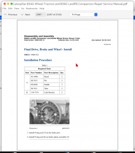
Final Drive; Brake and Wheel – Install…1097
Differential and Bevel Gear – Remove – Rear…1100
Differential and Bevel Gear – Disassemble…1104
Differential and Bevel Gear – Assemble…1117
Differential and Bevel Gear – Install – Rear…1140
NoSPIN Differential – Disassemble…1144
NoSPIN Differential – Assemble…1148
Oscillating Axle (Rear) – Install…1153
RENR2184 – Specifications (834G Wheel Dozer and 836G Landfill Compactor Steering System)…1157
Hydraulic Tank…1158
Breaker Relief Valve…1163
Oil Filter (Steering and Implement Pilot)…1164
Pressure Switch (Pilot Oil Filter Bypass)…1165
Relief Valve (Steering Pilot; Implement Pilot)…1167
Piston Pump (Steering)…1169
Check Valve (Steering Pilot)…1173
Pilot Valve (STIC Steering)…1174
Steering Control (Wheel Steering)…1176
Pilot Valve (Wheel Steering)…1178
Steering Neutralizer Valve…1181
Check Valve (Steering Quad)…1182
Steering Control Valve…1183
Pressure Reducing Valve (Steering)…1185
Relief Valve (Steering Cylinder Crossover)…1186
Relief Valve (Pump Backup)…1187
Steering Cylinder…1189
Articulated Hitch…1191
RENR2185 – Systems Operation (834G Wheel Tractor and 836G Landfill Compactor Steering System)…1194
General Information…1195
Monitoring System (Steering Functions)…1200
Steering Pilot System…1203
Pilot Valve (STIC Steering)…1207
Pilot Valve (Wheel Steering)…1211
Steering Neutralizer Valve…1213
Steering High Pressure System…1215
Piston Pump (Steering)…1218
Steering Control Valve…1227
RENR2186 – Testing and Adjusting (834G Wheel Dozer and 836G Landfill Compactor Steering System)…1233
Machine Preparation for Troubleshooting…1234
Visual Inspection…1237
Steering System Troubleshooting…1240
System Pressure – Release…1243
Hydraulic Oil Contamination – Test…1245
Pump Performance (Steering) – Test…1248
Relief Valve (Steering Pilot; Implement Pilot) – Test and Adjust…1250
Relief Valve (Steering Cylinder Crossover) – Test and Adjust…1253
Steering System Pressure (High Pressure Stall) – Test and Adjust…1258
Piston Pump (Steering) Low Pressure Standby – Test…1265
Piston Pump (Steering) Margin Pressure – Test and Adjust…1269
Relief Valve (Pump Backup) – Test and Adjust…1276
Steering Neutralizer Valve – Check and Adjust…1281
Steering Turn Stop – Adjust…1283
Steering Time – Check and Adjust…1285
Articulated Hitch – Adjust…1287
RENR2187 – Specifications (834G Wheel Tractor and 836G Landfill Compactor Braking System)…1292
Hydraulic Tank…1293
Breaker Relief Valve…1298
Gear Pump (Implement; Pilot; Brake)…1299
Brake Accumulator…1301
Accumulator Charging Valve (Brake)…1303
Pressure Switch (Brake Accumulator Charge)…1305
Foot Brake Control…1307
Limit Switch (Stop Light)…1310
Position Sensor (Torque Converter Impeller Clutch; Left Pedal)…1312
Limit Switch (Throttle Lock Deactivation; Right Pedal)…1313
Brake Control Valve (Service)…1315
Brake Control Valve (Parking)…1317
Pressure Switch (Parking Brake Oil)…1318
Parking Brake Control Cable…1320
Service Brakes…1321
Parking Brake…1323
RENR2188 – Systems Operation (834G Wheel Tractor and 836G Landfill Compactor Braking System)…1328
General Information…1329
Monitoring System (Braking Functions)…1333
Gear Pump (Implement; Pilot; Brake)…1335
Brake Accumulator…1337
Accumulator Charging Valve (Brake)…1339
Brake Control Valve (Service)…1342
Torque Converter Impeller Clutch Operation…1349
Brake Control Valve (Parking)…1351
Service Brakes…1355
Parking Brake…1357
Parking Brake Interlock…1360
RENR2189 – Testing and Adjusting (834G Wheel Dozer and 836G Landfill Compactor Braking System)…1362
Machine Preparation for Troubleshooting…1363
Visual Inspection…1366
Brake System Troubleshooting…1369
System Pressure – Release…1373
Hydraulic Oil Contamination – Test…1375
Brake Accumulator – Test and Charge…1378
Service Braking System Pressure – Test…1384
Service Brakes – Test…1387
Brake System Air – Purge…1390
Service Brake Discs – Check…1392
Limit Switch (Stop Light) – Adjust…1397
Limit Switch (Throttle Lock Deactivation) (Electronic Technician) – Adjust…1400
Parking Brake – Test…1407
Parking Brake System Air – Purge…1411
Parking Brake – Manual Release…1414
Parking Brake Control Cable – Adjust…1417
RENR2190 – Specifications (834G Wheel Dozer and 836G Landfill Compactor Electrohydraulic System)…1419
Hydraulic Tank…1420
Breaker Relief Valve…1425
Oil Filter (Steering and Implement Pilot)…1426
Pressure Switch (Pilot Oil Filter Bypass)…1427
Gear Pump (Implement; Pilot; Brake)…1429
Relief Valve (Steering Pilot; Implement Pilot)…1431
Relief Valve (Steering and Implement Pilot)…1433
Piston Pump (Hydraulic Fan)…1435
Gear Motor (Hydraulic Fan)…1439
Thermostatic Valve (Hydraulic Fan)…1441
Fan Reversing Valve…1442
Electrohydraulic Control…1445
Position Sensor (Control Lever)…1451
Pilot Control Actuator…1453
Combination Valve (Pilot Supply)…1455
Check Valve (Pilot)…1457
Main Control Valve…1458
Relief Valve (Main)…1462
Relief Valve (Line)…1464
Pinout Specifications for Implement Electronic Control…1466
Temperature Sensor (Hydraulic Oil)…1470
Check Valve (Hydraulic Oil Cooler Bypass)…1471
Lift Cylinder…1472
Bulldozer Pin…1474
Ground Engaging Tool Torques…1476
RENR2191 – Systems Operation (834G Wheel Tractor and 836G Landfill Compactor Electrohydraulic System)…1477
General Information…1478
Implement Electronic Control System…1482
Electronic Control Module (Implement)…1484
Switches…1488
Sensors…1490
Solenoid Valves…1494
Cat Data Link…1496
Monitoring System (Hydraulic Functions)…1498
Pilot Hydraulic System…1500
Gear Pump (Implement; Pilot; Brake)…1504
Relief Valve (Steering Pilot; Implement Pilot)…1506
Combination Valve (Pilot Supply)…1508
Pilot Control Actuator…1511
Main Hydraulic System…1514
Main Control Valve…1517
Relief Valve (Main)…1521
Relief Valve (Line)…1523
Hydraulic Fan System…1525
Piston Pump (Hydraulic Fan)…1530
Gear Motor (Hydraulic Fan)…1539
Fan Reversing Valve…1541
RENR2192 – Testing and Adjusting (834G Wheel Dozer and 836G Landfill Compactor Electrohydraulic System)…1544
Wiring Harness (Open Circuit) – Test…1545
Wiring Harness (Short Circuit) – Test…1547
Electrical Connector – Inspect…1549
Electronic Control Module (ECM) – Replace…1555
Electronic Control Module (ECM) – Flash Program…1556
Calibration…1557
Position Sensor for the Control Lever (Electronic Technician) – Calibrate…1558
Main Control Valve (Electronic Technician) – Calibrate…1560
Position Sensor for the Control Lever (Caterpillar Monitoring System) – Calibrate…1562
Main Control Valve (Caterpillar Monitoring System) – Calibrate…1564
System Pressure – Release…1570
Hydraulic Oil Contamination – Test…1572
Pump Performance – Test…1575
Torque Converter Stall – Test…1578
Torque Converter Stall and Implement Pump Double Stall – Test…1583
Lift Cylinder – Isolation and Drift Check…1588
Pilot Control Actuator Pressure – Check…1596
Relief Valve (Steering Pilot; Implement Pilot) – Test and Adjust…1599
Pressure Reducing Valve (Lowering Control) for Dead Engine Condition – Test and Adjust…1602
Relief Valve (Main) – Test and Adjust…1605
Relief Valve (Line) – Test and Adjust…1608
Piston Pump Cutoff Pressure (Hydraulic Fan) – Test and Adjust…1614
Piston Pump Margin Pressure (Hydraulic Fan) – Test and Adjust…1617
Glossary of Electrical Terms…1622
System Schematic…1624
RENR2192 – Troubleshooting (834G Wheel Dozer and 836G Landfill Compactor Electrohydraulic System)…1630
General Information…1632
Service Tools…1633
Connector Locations…1636
Diagnostic Capabilities…1638
Machine Preparation for Troubleshooting…1643
Visual Inspection…1645
Hydraulic System Troubleshooting…1648
Diagnostic Code List…1656
Using Caterpillar Electronic Technician to Determine Diagnostic Codes…1665
Using Caterpillar Monitoring System to Determine Diagnostic Codes…1667
MID 082 – CID 0168 – FMI 00…1670
MID 082 – CID 0168 – FMI 01…1672
MID 082 – CID 0296 – FMI 09…1674
MID 082 – CID 0296 – FMI 12…1680
MID 082 – CID 0352 – FMI 03…1685
MID 082 – CID 0352 – FMI 04…1690
MID 082 – CID 0352 – FMI 13…1693
MID 082 – CID 0353 – FMI 03…1695
MID 082 – CID 0353 – FMI 04…1700
MID 082 – CID 0353 – FMI 13…1703
MID 082 – CID 0354 – FMI 03…1705
MID 082 – CID 0354 – FMI 05…1708
MID 082 – CID 0354 – FMI 06…1711
MID 082 – CID 0354 – FMI 13…1714
MID 082 – CID 0355 – FMI 03…1716
MID 082 – CID 0355 – FMI 05…1719
MID 082 – CID 0355 – FMI 06…1722
MID 082 – CID 0355 – FMI 13…1725
MID 082 – CID 0356 – FMI 03…1727
MID 082 – CID 0356 – FMI 05…1730
MID 082 – CID 0356 – FMI 06…1733
MID 082 – CID 0356 – FMI 13…1736
MID 082 – CID 0357 – FMI 03…1738
MID 082 – CID 0357 – FMI 05…1741
MID 082 – CID 0357 – FMI 06…1744
MID 082 – CID 0357 – FMI 13…1747
MID 082 – CID 0358 – FMI 03…1749
MID 082 – CID 0358 – FMI 05…1752
MID 082 – CID 0358 – FMI 06…1755
MID 082 – CID 0490 – FMI 03…1758
MID 082 – CID 0490 – FMI 04…1763
MID 082 – CID 0562 – FMI 09…1768
MID 082 – CID 0562 – FMI 12…1774
MID 082 – CID 0590 – FMI 09…1779
MID 082 – CID 0590 – FMI 12…1785
MID 082 – CID 0591 – FMI 12…1790
MID 082 – CID 0650 – FMI 09…1792
MID 082 – CID 0650 – FMI 11…1796
MID 082 – CID 0650 – FMI 12…1801
MID 082 – CID 1393 – FMI 04…1805
MID 082 – CID 1400 – FMI 03…1807
MID 082 – CID 1400 – FMI 05…1810
MID 082 – CID 1400 – FMI 06…1813
RENR2193 – Disassembly and Assembly (834G Wheel Tractor and 836G Landfill Compactor Machine Systems)…1816
Steering Frame Lock – Separate and Connect…1819
System Pressure – Release…1822
Cab – Raise…1824
Cab – Lower…1840
Hydraulic Tank Guard – Remove…1851
Hydraulic Tank Guard – Install…1855
Hydraulic Tank – Remove…1859
Hydraulic Tank – Disassemble…1868
Hydraulic Tank – Assemble…1874
Hydraulic Tank – Install…1881
Relief Valve (Steering and Implement Pilot) – Remove and Install…1890
Pump Control Valve (Steering) – Remove and Install…1893
Piston Pump (Steering) – Remove…1896
Piston Pump (Steering) – Disassemble…1900
Piston Pump (Steering) – Assemble…1912
Piston Pump (Steering) – Install…1927
STIC Control and Pilot Valve (Steering) – Remove…1930
STIC Control and Pilot Valve (Steering) – Disassemble…1933
STIC Control and Pilot Valve (Steering) – Assemble…1942
STIC Control and Pilot Valve (Steering) – Install…1951
Steering Neutralizer Valve – Remove and Install…1953
Steering Control Valve – Remove…1956
Steering Control Valve – Disassemble…1961
Steering Control Valve – Assemble…1969
Steering Control Valve – Install…1978
Steering Cylinder – Remove…1982
Steering Cylinder – Install…1990
Brake Accumulator – Remove…1996
Brake Accumulator – Disassemble…2000
Brake Accumulator – Assemble…2003
Brake Accumulator – Install…2006
Accumulator Charging Valve (Brake) – Remove…2009
Accumulator Charging Valve (Brake) – Install…2013
Brake Control Valve (Service) – Remove and Install…2017
Brake Control Valve (Parking) – Remove and Install…2021
Parking Brake – Remove…2025
Parking Brake – Disassemble…2030
Parking Brake – Assemble…2033
Parking Brake – Install…2038
Gear Pump (Implement; Pilot and Braking) – Remove…2042
Gear Pump (Implement; Pilot and Braking) – Disassemble…2045
Gear Pump (Implement; Pilot and Braking) – Assemble…2052
Gear Pump (Implement; Pilot and Braking) – Install…2059
Pump Control Valve (Hydraulic Fan) – Remove and Install…2061
Piston Pump (Hydraulic Fan) – Remove…2065
Piston Pump (Hydraulic Fan) – Disassemble…2068
Piston Pump (Hydraulic Fan) – Assemble…2082
Piston Pump (Hydraulic Fan) – Install…2096
Thermostatic Valve (Hydraulic Fan) – Remove and Install…2099
Gear Motor (Hydraulic Fan) – Remove…2105
Gear Motor (Hydraulic Fan) – Disassemble…2107
Gear Motor (Hydraulic Fan) – Assemble…2112
Gear Motor (Hydraulic Fan) – Install…2116
Electrohydraulic Control – Remove…2118
Electrohydraulic Control – Install…2125
Main Control Valve – Remove…2131
Main Control Valve – Disassemble…2137
Main Control Valve – Assemble…2144
Main Control Valve – Install…2150
Combination Valve (Pilot Supply) – Remove…2155
Combination Valve (Pilot Supply) – Disassemble…2158
Combination Valve (Pilot Supply) – Assemble…2160
Combination Valve (Pilot Supply) – Install…2162
Fan Reversing Valve – Remove…2165
Fan Reversing Valve – Disassemble…2170
Fan Reversing Valve – Assemble…2178
Fan Reversing Valve – Install…2185
Blade – Remove…2189
Blade – Install…2194
Lift Cylinder – Remove…2198
Lift Cylinder – Install…2202
Window Wiper and Wiper Motor (Front) – Remove…2205
Window Wiper and Wiper Motor (Front) – Install…2210
Window Wiper and Wiper Motor (Rear) – Remove…2217
Window Wiper and Wiper Motor (Rear) – Install…2220
Swingout Ladder – Remove…2225
Swingout Ladder – Install…2228
Cab – Remove…2231
Cab – Install…2245
Operator Platform – Remove…2258
Operator Platform – Install…2262
Seat – Remove…2266
Seat – Install…2275
Evaporator Coil – Remove and Install…2283
Heater Coil – Remove and Install…2285
Blower Motor (Air Conditioner; Heater) – Remove…2287
Blower Motor (Air Conditioner; Heater) – Install…2293
Front Frame from Rear Frame – Separate…2299
Front Frame to Rear Frame – Connect…2314
RENR2194 – Schematic (834G Wheel Tractor and 836G Landfill Compactor Hydraulic System)…2333
Main…2334
Feature…2334
Cover Page…2335
Information…0
Component Location…0
Volume 1 of 2 – 836G Landfill Compactor…2336
Volume 2 of 2 – 834G Wheel Tractor…0
Page 1 of 2…2337
Page 2 of 2…2338
Tap Location…0
Volume 1 of 2 – 836G Landfill Compactor…2339
Volume 2 of 2 – 834G Wheel Tractor…2340
Related Manuals…2341
Fluid Power Symbols…2342
Electrical Symbols…2343
Schematic…0
Volume 1 of 2 – 836G Landfill Compactor…2344
Volume 2 of 2 – 834G Wheel Tractor…2345
Machine Views…0
Machine Component Locations – 836G…2346
Machine Component Locations – 834G…2347
Collage…2348
RENR2195 – Schematic (834G Wheel Tractor; 836G Landfill Compactor; and 988G Wheel Loader Electrical System)…2381
Main…2382
Features…2382
Cover Page…2383
Information…0
Component Location…0
Volume 1 of 2 – Cab …2384
Volume 2 of 2 – Engine and Chassis …2385
Connector Location…0
Volume 1 of 2 – Cab…2386
Volume 2 of 2 – Engine and Chassis …2387
CID / MID / FMI…0
Volume 1 of 2 – Cab…0
Page 1 of 3…2388
Page 2 of 3…2389
Page 3 of 3…2390
Volume 2 of 2 – Engine and Chassis …0
Page 1 of 3…2391
Page 2 of 3…2392
Page 3 of 3…2393
Specification and Related Manual…0
Volume 1 – Cab …2394
Volume 2 – Engine And Chassis…2395
Standard Electrical…2396
Schematics…0
Volume 1 – Cab …2397
Volume 2 – Engine and Chassis…2398
Machine View…0
Cab – Front and Top View …2399
838G – Top and Rigth Side View …2400
836G – Top and Rigth Side View…2401
988G – Top and Rigth Side View…2402
Dash Front and Rear View…2403
View of Area – 938G…2404
View of Area 834G and 846G…2405
Collage…2406
RENR2196 – Disassembly and Assembly (834G Wheel Tractor and 836G Landfill Compactor Engine Supplement)…2438
Steering Frame Lock – Separate and Connect…2440
System Pressure – Release…2443
Hood and Engine Enclosure – Remove…2445
Hood and Engine Enclosure – Install…2455
Hood Panels (Front and Rear) – Remove…2464
Hood Panels (Front and Rear) – Install…2471
Belt Tensioner – Remove and Install…2477
Alternator – Remove and Install…2483
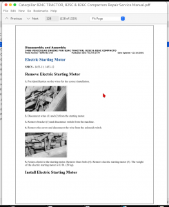
Electric Starting Motor – Remove…2490
Electric Starting Motor – Install…2496
Fuel Tank – Remove…2502
Fuel Tank – Install…2512
Water Temperature Regulator – Remove and Install – Engine In Chassis…2521
Water Pump – Remove – Engine In Chassis…2532
Water Pump – Install – Engine In Chassis…2537
Crankshaft Front Seal and Wear Sleeve – Remove – Engine In Chassis…2541
Crankshaft Front Seal and Wear Sleeve – Install – Engine In Chassis…2544
Radiator Top Tank – Remove…2548
Radiator Top Tank – Install…2553
Radiator Core – Remove…2557
Radiator Core – Install…2561
Radiator Guard – Remove…2565
Radiator Guard – Install…2574
Fan Group (Includes Fan; Fan Shroud; and Hydraulic Fan Motor) – Remove…2582
Fan Group (Includes Fan; Fan Shroud; and Hydraulic Fan Motor) – Install…2588
Fan Shroud – Remove…2593
Fan Shroud – Install…2596
Fan Blade (Spider) – Remove…2600
Fan Blade (Spider) – Install…2605
Hydraulic Oil Cooler – Remove…2608
Hydraulic Oil Cooler – Install…2613
Transmission Oil Cooler – Remove – Engine In Chassis…2617
Transmission Oil Cooler – Install – Engine In Chassis…2623
Engine Oil Cooler – Remove – Engine In Chassis…2628
Engine Oil Cooler – Install – Engine In Chassis…2631
Turbocharger – Remove – Engine In Chassis…2634
Turbocharger – Install – Engine In Chassis…2639
Aftercooler – Remove…2643
Aftercooler – Install…2646
Air Cleaner – Remove…2649
Air Cleaner – Install…2654
Muffler – Remove and Install…2659
Refrigerant Compressor – Remove and Install – Engine In Chassis…2665
Refrigerant Condenser – Remove and Install…2670
Engine and Torque Converter – Remove…2677
Engine from Torque Converter – Separate…2690
Engine to Torque Converter – Connect…2693
Engine and Torque Converter – Install…2695
RENR6005 – Specifications (988G Wheel Loader; 834G Wheel Tractor and 836G Landfill Compactor Machine Systems)…2708
Cab Mounting…2709
Window Wiper and Wiper Motor…2711
Governor Pedal…2714
Position Sensor (Throttle)…2716
Fuel Level Sender…2717
Engine Brake Switch…2719


INSTANT DOWNLOAD


Caterpillar 834G Wheel Tractors and 836G Landfill Compactors Repair Service Manual

Posted on

Caterpillar 824C TRACTOR, 825C & 826C Compactors Repair Service Manual

Caterpillar 824C TRACTOR, 825C & 826C Compactors Repair Service Manual

INSTANT DOWNLOAD


Complete service repair manual with Electrical Wiring Diagrams for Caterpillar 824C TRACTOR, 825C & 826C Compactors, with all the technical information to maintain, diagnose, repair, rebuild like professional mechanics.

Caterpillar 824C TRACTOR, 825C Compactor & 826C Compactor workshop service repair manual includes:
* Numbered table of contents easy to use so that you can find the information you need fast.
* Detailed sub-steps expand on repair procedure information
* Numbered instructions guide you through every repair procedure step by step.
* Troubleshooting and electrical service procedures are combined with detailed wiring diagrams for ease of use.
* Notes, cautions and warnings throughout each chapter pinpoint critical information.
* Bold figure number help you quickly match illustrations with instructions.
* Detailed illustrations, drawings and photos guide you through every procedure.
* Enlarged inset helps you identify and examine parts in detail.

PRODUCT DETAILS:
Total Pages: 1,051 pages
File Format: PDF (Internal Links, Bookmarked, Table of Contents, Searchable, Printable, high quality)
Language: English

SENR7852 – Disassembly and Assembly (824C TRACTOR, 825C & 826C COMPACTORS OPERATOR’S STATION).pdf
SENR7849 – Disassembly and Assembly (824C TRACTOR, 825C & 826C COMPACTOR VEHICLE SYSTEMS).pdf
SENR7835 – Disassembly and Assembly (824C TRACTOR, 825C & 826C COMPACTORS POWER TRAIN).pdf
SENR4732 – Schematic (826C Compactor Electrical System, 8T-9753).pdf
SENR7976 – Schematic (826C Landfill Compactor Hydraulic System).pdf
SENR2585 – Schematic (824C Tractor, 825C & 826C Compactors Electrical System).pdf
SENR2552 – Schematic (824C Tractor, 825C & 826C Compactors Electrical System).pdf
SENR7832 – Specifications (824C TRACTOR, 825C & 826C COMPACTORS POWER TRAIN).pdf
SENR7840 – Specifications (824C WHEEL TRACTOR, 825C & 826C COMPACTORS AIR SYSTEM & BRAKE).pdf
SENR7842 – Specifications (824C BULLDOZER HYDRAULIC SYSTEM).pdf
SENR7844 – Specifications (825C & 826C BULLDOZER HYDRAULIC SYSTEM).pdf
SENR7836 – Specifications (824C TRACTOR, 825C & 826C COMPACTORS STEERING SYSTEM).pdf
SENR7834 – Testing and Adjusting (824C TRACTOR, 825C & 826C COMPACTORS POWER SHIFT TRANSMISSION).pdf
SENR7833 – Systems Operation (824C WHEEL TRACTOR, 824C & 825C COMPACTORS POWER TRAIN).pdf
SENR7837 – Testing and Adjusting (824C TRACTOR, 825C & 826C COMPACTORS STEERING SYSTEM).pdf
SENR7837 – Systems Operation (824C TRACTOR, 825C & 826C COMPACTORS STEERING SYSTEM).pdf
SENR7841 – Testing and Adjusting (824C TRACTOR 825C & 826C COMPACTORS AIR SYSTEM AND BRAKES).pdf
SENR7841 – Systems Operation (824C TRACTOR 825C & 826C COMPACTORS AIR SYSTEM AND BRAKES).pdf
SENR7845 – Testing and Adjusting (825C & 826C BULLDOZER HYDRAULIC SYSTEM).pdf
SENR7845 – Systems Operation (825C & 826C BULLDOZER HYDRAULIC SYSTEM).pdf
SENR7843 – Testing and Adjusting (824C BULLDOZER HYDRAULIC SYSTEM).pdf
SENR7843 – Systems Operation (824C BULLDOZER HYDRAULIC SYSTEM).pdf
SENR2586 – Schematic (824C Tractor, 825C and 826C Compactor Electrical System (For Serial Numbers 85X763-1193, 86X507-730, 87X249-586)).pdf

MAIN SECTIONS
SENR2552 – Schematic (824C Tractor, 825C & 826C Compactors Electrical System)…3
Collage…4
Main…34
SENR2585 – Schematic (824C Tractor, 825C & 826C Compactors Electrical System)…36
Collage…37
Main…49
SENR2586 – Schematic (824C Tractor, 825C and 826C Compactor Electrical System (For Serial Numbers 85X763-1193, 86X507-730, 87X249-586))…51
SENR4732 – Schematic (826C Compactor Electrical System, 8T-9753)…59
Collage…60
Main…72
SENR7832 – Specifications (824C TRACTOR, 825C & 826C COMPACTORS POWER TRAIN)…74
Axle Group (Fixed)…75
Axle Group (Oscillating)…76
Cleaner Bar Group…78
Differential And Bevel Gear…79
Differentials…89
Drive Shaft…90
Final Drives, Brakes And Wheels…92
Frame Group Engine End…96
Introduction…102
Pump Drive…103
Relief Valve For Converter Outlet…105
Rim Group…107
Selector And Pressure Control Valve For Transmission…108
Torque Converter…113
Transfer Gears…116
Transmission Hydraulic Controls…118
Transmission Neutralizer Group…119
Transmission Oil Filter…121
Transmission Oil Pump…123
Transmission…125
Wheel Assembly…128
Wheel Bearing Adjustment…130
SENR7833 – Systems Operation (824C WHEEL TRACTOR, 824C & 825C COMPACTORS POWER TRAIN)…136
SENR7834 – Testing and Adjusting (824C TRACTOR, 825C & 826C COMPACTORS POWER SHIFT TRANSMISSION)…203
SENR7835 – Disassembly and Assembly (824C TRACTOR, 825C & 826C COMPACTORS POWER TRAIN)…217
Anti-Pivot Link…219
Center Drive Shaft…221
Differential And Bevel Gear (824C)…223
Differential And Bevel Gear (825C, 826C)…240
Drive Axles (824C)…258
Drive Axles (825C, 826C)…261
Final Drive Carriers And Ring Gears (825C, 826C)…265
Final Drive Planet Carriers (824C)…268
Front Axle Housing (824C)…273
Front Axle Housing (825C, 826C)…275
Front Differential And Bevel Gear (824C)…278
Front Differential And Bevel Gear (825C, 826C)…281
Front Drive Shaft…284
Front Support (824C)…289
Front Support (825C, 826C)…294
Front Tires And Rims (824C)…299
Parking Brake…302
Power Train Guard…311
Rear Axle Housing (824C)…313
Rear Axle Housing (825C, 826C)…316
Rear Differential And Bevel Gear (825C, 826C)…319
Rear Differential and Bevel (824C)…321
Rear Drive Shaft…324
Rear Support (824C)…326
Rear Support (825C, 826C)…332
Rear Tires And Rims (824C)…336
Torque Converter Outlet Relief Valve…340
Torque Converter, Transmission And Transfer Gears…348
Torque Converter…363
Transfer Gears…386
Transmission Charging Pump…403
Transmission Hydraulic Control Valve…410
Transmission Neutralizer Group…422
Transmission Oil Filter…429
Transmission Support Assembly (825C, 826C)…433
Transmission…436
Wheel Assemblies And Wheel Brake Assemblies (824C)…472
Wheel Assemblies And Wheel Brake Assemblies (825C & 826C)…486
Wheels (825C)…497
SENR7836 – Specifications (824C TRACTOR, 825C & 826C COMPACTORS STEERING SYSTEM)…500
824C & 826C Hydraulic Pump…501
825C Hydraulic Pump…504
Diverter Valve For Supplemental Steering…507
Filter Bypass Valve…509
Flow Switch For Supplemental Steering…510
Hand Metering Unit…511
Hitch Bearing Adjustments…512
Introduction…515
Neutralizer Valves…516
Steering Control Group…518
Steering Control Valve…519
Steering Cylinders…522
Supplemental Steering Pump…523
SENR7837 – Systems Operation (824C TRACTOR, 825C & 826C COMPACTORS STEERING SYSTEM)…525
SENR7837 – Testing and Adjusting (824C TRACTOR, 825C & 826C COMPACTORS STEERING SYSTEM)…538
SENR7840 – Specifications (824C WHEEL TRACTOR, 825C & 826C COMPACTORS AIR SYSTEM & BRAKE)…551
Air Compressor Governor…552
Air Pressure Switches…553
Air Relief Valve…554
Air_Hydraulic Cylinder Group…555
Air_Quick Release Valve…557
Brake Control Valve…558
Introduction…561
Parking Brake Group…562
Service Brakes…566
SENR7841 – Systems Operation (824C TRACTOR 825C & 826C COMPACTORS AIR SYSTEM AND BRAKES)…570
SENR7841 – Testing and Adjusting (824C TRACTOR 825C & 826C COMPACTORS AIR SYSTEM AND BRAKES)…614
SENR7842 – Specifications (824C BULLDOZER HYDRAULIC SYSTEM)…644
Check Valve SMCS – 5050…645
HYDRAULIC PUMP 3G3153…647
HYDRAULIC PUMP 3G4089…650
HYDRAULIC PUMP 3G4602…652
HYDRAULIC PUMP 3G7480…655
Hydraulic Control Levers SMCS – 5050…656
Hydraulic Cylinders SMCS – 5050…660
Introduction SMCS – 5050…662
Lift Cylinder and Bulldozer Installation SMCS – 5050…663
SENR7843 – Systems Operation (824C BULLDOZER HYDRAULIC SYSTEM)…664
SENR7843 – Testing and Adjusting (824C BULLDOZER HYDRAULIC SYSTEM)…678
SENR7844 – Specifications (825C & 826C BULLDOZER HYDRAULIC SYSTEM)…690
Hydraulic Control Lever SMCS – 5050…691
Hydraulic Control Valves SMCS – 5050…693
Hydraulic Cylinders SMCS – 5050…696
Hydraulic Pumps SMCS – 5050…699
Hydraulic Tank 3G4089…704
Introduction SMCS – 5050…706
Lift Cylinder Mounting (826C)…707
SENR7845 – Systems Operation (825C & 826C BULLDOZER HYDRAULIC SYSTEM)…709
SENR7845 – Testing and Adjusting (825C & 826C BULLDOZER HYDRAULIC SYSTEM)…716
SENR7849 – Disassembly and Assembly (824C TRACTOR, 825C & 826C COMPACTOR VEHICLE SYSTEMS)…727
Air Reservoir…729
Air_Hydraulic Cylinder Group…731
Anti-Pivot Link…736
Bulldozer (825C)…738
Bulldozer Group (824C)…741
Cleaner Bars-Engine End (Front And Rear) (825C)…746
Cleaner Bars-Non Engine End (Front) (825C)…750
Cleaner Bars-Non Engine End (Rear) (825C)…752
Differential Pressure Switch…755
Foot-Operated Brake Valves…758
Hand Metering Pump…763
Hydraulic Control Valve And Pilot Operated Relief Valve (824C)…771
Hydraulic Control Valve And Pilot Operated Relief Valve (825C, 826C)…774
Hydraulic Control Valve And Pilot Operated Relief Valve…777
Hydraulic Tank Oil Filter…784
Hydraulic Tank…786
Implement Steering Pump…797
Lift And Tilt Cylinders (825C, 826C)…809
Lift Cylinder (824C)…816
Lift Cylinder (825C, 826C)…825
Lift Cylinder Trunnion Assembly (824C)…827
Main Frames…829
Parking Brake Control Valve…844
Parking Brake…846
Slack Adjusters…855
Stabilizer Bearings (824C)…858
Steering Control Valve…861
Steering Cylinders…868
Steering Neutralizer Valves…878
Tag Link (825C)…882
Tilt And Tip Check Valve (824C)…883
Tilt And Tip Cylinders (824C)…888
Tilt Cylinder (825C)…898
Transmission Neutralizer Group…901
Trunnion Support (825C)…908
SENR7852 – Disassembly and Assembly (824C TRACTOR, 825C & 826C COMPACTORS OPERATOR'S STATION)…913
ADJUSTABLE STEERING COLUMN…914
AIR CONDITIONER GROUP…930
AIR HORN GROUP…938
CAB AND PLATFORM…941
CAB DOOR AND STRIKER…948
CAB DOOR GLASS…954
CAB HEATER…959
CAB PRESSURIZER GROUP…963
CAB…970
FUSE PANEL…977
GOVERNOR PEDAL GROUP…981
INSTRUMENT PANEL…986
MIRROR…995
PARKING BRAKE CABLE…996
ROLLOVER PROTECTIVE STRUCTURE (ROPS)…999
SEAT…1001
SOUND SUPPRESSION…1018
STEERING WHEEL…1021
WINDOW WASHER BOTTLE…1023
WINDSHIELD WIPER MOTOR, LINKAGE AND WASHER…1025
WINDSHIELD WIPER MOTORS AND LINKAGE…1029
SENR7976 – Schematic (826C Landfill Compactor Hydraulic System)…1033
Collage…1034
Main…1050


INSTANT DOWNLOAD


Posted on

Peugeot Models 205, 206, 306, 307, 309, 405, 406 Repair Service Manual


Complete service repair manual with Electrical Wiring Diagrams for Peugeot Models 205, 206, 306, 307, 309, 405, 406, with all the technical information to maintain, diagnose, repair, and rebuild like professional mechanics.

Peugeot Models 205, 206, 306, 307, 309, 405, 406 workshop service repair manual includes:
* Numbered table of contents easy to use so that you can find the information you need fast.
* Detailed sub-steps expand on repair procedure information
* Numbered instructions guide you through every repair procedure step by step.
* Troubleshooting and electrical service procedures are combined with detailed wiring diagrams for ease of use.
* Notes, cautions and warnings throughout each chapter pinpoint critical information.
* Bold figure number help you quickly match illustrations with instructions.
* Detailed illustrations, drawings and photos guide you through every procedure.
* Enlarged inset helps you identify and examine parts in detail.


INSTANT DOWNLOAD


Peugeot 406 Service Manual ’98- (FR)
Peugeot 205 Service & Repair Manual ’83-’97.pdf
Peugeot 206 Service & Repair Manual ’98-’09
Peugeot 306 gasolina y diesel ’93-’95 Service & Repair Manual (ES).pdf
Peugeot 306 Service & Repair Manual (EN) ’93-’95.pdf
Peugeot 307 Service & Repair Manual ’01-’04.pdf
Peugeot 309 Service & Repair Manual ’85-’97.pdf
Peugeot 405 Service & Repair Manual ’88-’97.pdf
Peugeot 406 Service & Repair Manual ’99-’02.pdf

PRODUCT DETAILS:
Total Pages: 2,234 pages
File Format: PDF
Language: English / French

TABLE OF CONTENTS
Peugeot 205 Service & Repair Manual ’83-’97…………….1
Peugeot 306 Service & Repair Manual (EN) ’93-’95…………….235
Peugeot 306 gasolina y diesel ’93-’95 Service & Repair Manual (ES)…………….567
Peugeot 307 Service & Repair Manual ’01-’04…………….735

Peugeot 309 Service & Repair Manual ’85-’97…………….1077
00. Living with your peugeot 309…………….1078
01. Engine…………….1093
02. Cooling system…………….1133
03. Fuel and exhause systems…………….1139
04. Ignition system…………….1153
05. Clutch…………….1161
06. Transmission…………….1165
07. Driveshafts…………….1171
08. Braking system…………….1173
09. Suspension hubs wheels and tyres…………….1187
10. Steering…………….1197
11. Bodywork and fitting…………….1201
12. Electrical system…………….1215
13. Supplement…………….1233
14. Wiring diagrams…………….1295
15. Ref…………….1309
Peugeot 405 Service & Repair Manual ’88-’97…………….1330
Peugeot 406 Service & Repair Manual ’99-’02…………….1632
Peugeot 406 Service Manual ’98- (FR)…………….2015
01…………….2015
PRÉSENTATION…………….2016
LIGNE -ÉQUIPEMENT…………….2017
02…………….2018
CARACTÉRISTIQUES…………….2018
Caractéristiques dimensionnelles et pondérales…………….2018
CARROSSERIE…………….2018
DIMENSIONS (mm)…………….2018
POIDS ET CHARGES (kg)…………….2018
Caractéristiques pratiques…………….2019
CAPACITÉS (l)…………….2019
PERFORMANCES (à titre indicatif pour la berline)…………….2019
CONSOMMATIONS (l)…………….2019
Identifications intérieures…………….2020
TEINTES PEINTURE…………….2020
03a…………….2022
CARACTÉRISTIQUES…………….2022
GÉNÉRALITÉS…………….2022
IDENTIFICATION DES MOTEURS…………….2022
SPÉCIFICATIONS GÉNÉRALES…………….2022
BLOC-CYLINDRES…………….2022
CHEMISES (sauf XU10)…………….2022
PISTONS…………….2023
AXES DE PISTONS…………….2024
SEGMENTS…………….2024
BIELLES…………….2024
VILEBREQUIN…………….2024
JEU PALIER DE VILEBREQUIN…………….2024
CHOIX DES COUSSINETS…………….2025
CULASSE…………….2026
SOUPAPES…………….2026
SIÈGES DE SOUPAPES (mm)…………….2026
GUIDES DE SOUPAPES (mm)…………….2027
DISTRIBUTION…………….2027
LUBRIFICATION…………….2027
CAPACITÉS (l)…………….2027
PRESSION D’HUILE…………….2027
REFROIDISSEMENT…………….2028
VASE D’EXPANSION…………….2028
THERMOSTAT…………….2028
MOTOVENTILATEUR ET THERMOCONTACT…………….2028
ALLUMAGE – INJECTION…………….2028
CARACTÉRISTIQUES DES SYSTÈMES D’INJECTION…………….2028
BOUGIES…………….2028
BOBINES…………….2028
CONTRÔLES…………….2028
CULASSE…………….2030
PLANS D’ENTRETIEN-RÉPARATION…………….2030
MÉTHODES DE RÉPARATION…………….2030
Dépose-repose du groupe motopropulseur…………….2030
Moteur 8 soupapes…………….2030
DÉPOSE…………….2030
REPOSE…………….2031
Moteur 16 soupapes……………..2031
DÉPOSE…………….2031
REPOSE…………….2032
Mise au point moteur…………….2032
Jeu aux poussoirs…………….2032
CONTRÔLE…………….2032
Distribution…………….2033
Moteur 8 soupape…………….2033
DÉPOSE DE LA COURROIE…………….2033
REPOSE DE LA COURROIE…………….2034
CONTRÔLE DU CALAGE ET CONTRÔLE DU CALAGE ET COURROIE…………….2034
Moteur 16 soupapes…………….2034
DÉPOSE DE LA COURROIE…………….2034
REPOSE DE LA COURROIE…………….2034
CONTRÔLE DE LA TENSION…………….2035
Lubrification…………….2037
Refroidissement…………….2037
REMPLISSAGE ET PURGE…………….2037
Allumage – injection…………….2038
Moteurs XU5 et XU7JB injection Magneti Marelli…………….2038
CONTRÔLE DE LA PRESSION D’ALIMENTATION…………….2038
CONTRÔLE CHUTE DE PRESSION…………….2038
CONTRÔLE DU DÉBIT…………….2039
CONTRÔLE RALENTI…………….2039
CONTRÔLE ANTIPOLLUTION…………….2039
CONTRÔLE ET RÉGLAGE AVANCE ALLUMAGE…………….2039
Moteur XU10J2TE injection Bosch MP3.2…………….2040
CONTRÔLE DE LA PRESSION D’ALIMENTATION…………….2040
CONTRÔLE CHUTE DE PRESSION…………….2040
CONTRÔLE DU DÉBIT…………….2040
CONTRÔLE RALENTI…………….2040
CONTRÔLE ANTIPOLLUTION…………….2040
CONTRÔLE ET RÉGLAGE AVANCE ALLUMAGE…………….2040
Moteurs XU7JP4 et XU10J4R injection Bosch MP5.1.1…………….2040
CONTRÔLE DE LA PRESSION D’ALIMENTATION…………….2040
CONTRÔLE DU DÉBIT…………….2040
CONTRÔLE RALENTI…………….2040
CONTRÔLE ANTIPOLLUTION…………….2040
CONTRÔLE AVANCE ALLUMAGE…………….2040
Révision de la culasse…………….2040
Moteurs XU5, XU7JB et XU10J2TE (simple arbre à cames)…………….2040
Dépose…………….2040
Démontage…………….2041
Contrôle…………….2041
Remontage…………….2041
Repose…………….2041
Moteurs XU7JP4 et XU10J4R (double arbres à cames)…………….2042
Dépose…………….2042
Démontage…………….2042
Contrôles…………….2043
Remontage…………….2043
Repose…………….2043
03b…………….2045
CARACTÉRISTIQUES…………….2045
GÉNÉRALITÉS…………….2045
IDENTIFICATION…………….2045
ATTELAGE MOBILE…………….2045
SPÉCIFICATIONS GÉNÉRALES…………….2045
Éléments constitutifs du moteur…………….2045
CARTER CYLINDRES…………….2045
VILEBREQUIN…………….2045
DEMI-COUSSINETS DE VILEBREQUIN…………….2045
BIELLE / PISTONS…………….2046
CARTERS DE CHAPEAUX DE PALIERS D’ARBRES À CAMES…………….2046
CULASSE…………….2046
ARBRES À CAMES…………….2046
JOINT DE CULASSE…………….2046
DISTRIBUTION…………….2046
LUBRIFICATION…………….2047
REFROIDISSEMENT…………….2047
ALLUMAGE – INJECTION…………….2047
MÉTHODES DE RÉPARATION…………….2049
Dépose – repose du groupe motopropulseur…………….2049
DÉPOSE…………….2049
REPOSE…………….2050
Mise au point moteur…………….2050
Jeu aux soupapes…………….2050
Distribution…………….2050
DÉPOSE DE LA COURROIE…………….2050
REPOSE DE LA COURROIE…………….2051
Lubrification…………….2052
Refroidissement…………….2052
VIDANGE…………….2052
REMPLISSAGE – PURGE…………….2053
Allumage – injection…………….2053
APPRENTISSAGE DU RALENTI MOTEUR…………….2053
AUTO-ADAPTIVITÉ DE LA RICHESSE…………….2053
ANALYSE DES DÉFAUTS…………….2053
Révision de la culasse…………….2054
Dépose de la culasse…………….2054
CONTRÔLE DE LA PLANÉITÉ…………….2054
CONTRÔLE DES VIS DE CULASSE…………….2055
DÉPOSE DES ARBRES À CAMES…………….2055
REPOSE DES ARBRES À CAMES…………….2055
IDENTIFICATION DES ARBRES À CAMES…………….2055
Repose de la culasse…………….2055
Interventions sur le moteur ne nécessitant pas sa dépose…………….2056
Dépose-repose joints à lèvres…………….2056
ÉCHANGE DU JOINT À LÈVRES D’ARBRE À CAMES…………….2056
ÉCHANGE DU JOINT À LÈVRES VILEBREQUIN (CÔTÉ DISTRIBUTION)…………….2057
ÉCHANGE DU JOINT À LÈVRES VILEBREQUIN (CÔTÉ VOLANT MOTEUR)…………….2057
Dépose-repose pompe à huile…………….2057
DÉPOSE…………….2057
REPOSE…………….2058
03c…………….2059
CARACTÉRISTIQUES…………….2059
GÉNÉRALITÉS…………….2059
SPÉCIFICATIONS GÉNÉRALES…………….2059
BLOC-CYLINDRES…………….2059
PISTONS…………….2060
VILEBREQUIN…………….2060
BIELLES…………….2060
CULASSE…………….2061
SOUPAPES…………….2061
SIÈGES DE SOUPAPES…………….2062
GUIDES DE SOUPAPES…………….2062
CHAMBRES DE TURBULENCE…………….2062
DISTRIBUTION…………….2063
ARBRE A CAMES…………….2063
JEUX AUX POUSSOIRS…………….2063
LUBRIFICATION…………….2063
POMPE A HUILE…………….2063
REFROIDISSEMENT…………….2063
THERMOSTAT…………….2063
MOTOVENTILATEUR…………….2063
THERMOCONTACT…………….2064
INJECTION…………….2064
POMPE D’INJECTION…………….2064
INJECTEURS…………….2064
SURALIMENTATION…………….2065
MÉTHODES DE RÉPARATION…………….2065
Dépose – repose du groupe motopropulseur…………….2065
DÉPOSE…………….2065
REPOSE…………….2066
Mise au point du moteur…………….2066
Jeu aux soupapes…………….2066
CONTRÔLE…………….2066
RÉGLAGE…………….2066
Distribution…………….2067
Moteur XUD9…………….2067
DÉPOSE DE LA COURROIE CRANTÉE…………….2067
REPOSE DE LA COURROIE CRANTÉE…………….2067
CONTRÔLE DU CALAGE DE LA DISTRIBUTION…………….2067
Moteur XUD11…………….2068
DÉPOSE DE LA COURROIE CRANTÉE…………….2068
REPOSE DE LA COURROIE CRANTÉE…………….2068
CONTRÔLE DU CALAGE DE LA DISTRIBUTION…………….2068
Lubrification…………….2069
CONTRÔLE DE LA PRESSION D’HUILE…………….2069
Refroidissement…………….2069
VIDANGE…………….2069
REMPLISSAGE ET PURGE…………….2069
Alimentation…………….2070
REMPLACEMENT FILTRE À GAZOLE…………….2070
Injection…………….2070
Moteur XUD9 (équipement Bosch)…………….2070
DÉPOSE POMPE D’INJECTION…………….2070
REPOSE POMPE D’INJECTION…………….2070
CALAGE DE LA POMPE D’INJECTION…………….2071
RÉGLAGES POMPE D’INJECTION…………….2071
Moteur XUD11 (équipement Lucas type Epic)…………….2073
DÉPOSE POMPE INJECTION…………….2073
REPOSE POMPE INJECTION…………….2073
CALAGE DE LA POMPE D’INJECTION…………….2073
RÉGLAGES POMPE D’INJECTION…………….2074
Injecteurs…………….2074
DÉPOSE…………….2074
REPOSE…………….2074
CONTRÔLE DES INJECTEURS…………….2074
Révision de la culasse…………….2075
Dépose…………….2075
Démontage…………….2075
Contrôle…………….2076
CONTRÔLE DU PLAN DE JOINT…………….2076
SOUPAPES…………….2076
PRÉCHAMBRES…………….2076
Remontage…………….2076
Repose…………….2077
04…………….2079
CARACTÉRISTIQUES…………….2079
MÉTHODES DE RÉPARATION…………….2079
Dépose-repose embrayage…………….2079
Pour BV BE 3/5…………….2079
DÉPOSE…………….2079
REPOSE…………….2079
Pour BV ML 5T…………….2079
DÉPOSE…………….2079
REPOSE…………….2079
Contrôles commande de débrayage à câble avec rattrapage automatique…………….2080
Déblocage commande de débrayage à câble avec rattrapage automatique (embrayage poussé)…………….2080
Déblocage commande de débrayage à câble avec rattrapage (embrayage tiré)…………….2080
Contrôle course de la pédale d’embrayage (BV ML 5T)…………….2080
Dépose-repose commande hydraulique d’embrayage…………….2081
DÉPOSE…………….2081
REPOSE D’UNE COMMANDE NEUVE…………….2081
05a…………….2082
CARACTÉRISTIQUES…………….2082
LUBRIFICATION…………….2082
IDENTIFICATION BOÎTES DE VITESSES…………….2082
RAPPORTS DE TRANSMISSION…………….2083
MÉTHODES DE RÉPARATION…………….2083
Dépose-repose boîte de vitesses (embrayage tiré) (B.V. BE3/5)…………….2083
DÉPOSE…………….2083
REPOSE…………….2084
Dépose-repose boîte de vitesses (embrayage poussé) (B.V. BE3/5)…………….2084
DÉPOSE…………….2084
REPOSE…………….2085
Dépose-repose boîte de vitesses (B.V.ML5T)…………….2085
DÉPOSE…………….2085
REPOSE…………….2086
Dépose-repose commande de vitesses à câbles (B.V. ML5T)…………….2086
DÉPOSE…………….2086
REPOSE…………….2087
05b…………….2088
CARACTÉRISTIQUES…………….2088
SPÉCIFICATIONS GÉNÉRALES…………….2088
RAPPORTS DE TRANSMISSION…………….2088
ÉVOLUTION…………….2088
MÉTHODES DE RÉPARATION…………….2089
CONTRÔLE NIVEAU D’HUILE…………….2089
VIDANGE EN CAS D’INTERVENTION…………….2089
REMPLISSAGE…………….2089
06…………….2090
CARACTÉRISTIQUES…………….2090
TABLEAUX D’AFFECTATION DES TRANSMISSIONS…………….2090
MÉTHODES DE RÉPARATION…………….2090
Dépose-repose transmission…………….2090
DÉPOSE…………….2090
REPOSE…………….2090
07a…………….2091
CARACTÉRISTIQUES…………….2091
SPÉCIFICATIONS GÉNÉRALES…………….2091
BARRE ANTIDÉVERS…………….2091
AFFECTATION DES RESSORTS…………….2091
MÉTHODES DE RÉPARATION…………….2092
Suspension AV…………….2092
Élément de suspension…………….2092
DÉPOSE…………….2092
REPOSE…………….2092
Amortisseur…………….2093
DÉPOSE…………….2093
REPOSE…………….2093
Palier de barre antidévers…………….2093
DÉPOSE…………….2093
IDENTIFICATION DES PALIERS…………….2093
REPOSE…………….2094
Train AV Triangle AV…………….2094
DÉPOSE…………….2094
REPOSE…………….2094
Articulations élastiques de triangle…………….2094
DÉPOSE…………….2094
REPOSE…………….2094
Pivot…………….2094
DÉPOSE…………….2094
REPOSE…………….2095
Roulement de roue AV…………….2095
DÉPOSE…………….2095
REPOSE…………….2095
Berceau…………….2096
DÉPOSE…………….2096
REPOSE…………….2096
Articulation élastique berceau AV…………….2096
DÉPOSE…………….2096
REPOSE…………….2097
07b…………….2098
CARACTÉRISTIQUES…………….2098
SPÉCIFICATIONS GÉNÉRALES…………….2098
BARRE ANTIDÉVERS…………….2098
AFFECTATION DES RESSORTS…………….2098
MÉTHODES DE RÉPARATION…………….2099
Suspension AR…………….2099
Amortisseur AR…………….2099
DÉPOSE…………….2099
REPOSE…………….2099
Paliers de barre antidévers…………….2099
DÉPOSE – REPOSE…………….2099
Train AR…………….2099
Train AR complet…………….2099
DÉPOSE…………….2099
REPOSE…………….2100
Articulation élastique de la traverse AR…………….2100
DÉPOSE…………….2100
REPOSE…………….2100
Bras longitudinal AR…………….2101
DÉPOSE…………….2101
REPOSE…………….2101
Articulation élastique du bras longitudinal AR…………….2101
DÉPOSE…………….2101
REPOSE…………….2101
Articulation élastique de palier AV du bras longitudinal…………….2101
DÉPOSE…………….2101
REPOSE…………….2101
Bras inférieur…………….2102
DÉPOSE…………….2102
REPOSE…………….2102
Pivot AR…………….2102
DÉPOSE…………….2102
REPOSE…………….2102
Articulation de pivot AR…………….2103
DÉPOSE…………….2103
REPOSE…………….2103
Moyeu-roulement AR…………….2103
DÉPOSE…………….2103
REPOSE…………….2103
08…………….2104
CARACTÉRISTIQUES…………….2104
Train AV…………….2104
PARALLÉLISME…………….2104
CHASSE…………….2104
CARROSSAGE…………….2104
PIVOT…………….2104
Train AR…………….2104
HAUTEUR DE CAISSE…………….2104
CARROSSAGE…………….2104
PARALLÉLISME…………….2104
MÉTHODES DE RÉPARATION…………….2104
Train AV…………….2104
PRÉCONISATION…………….2104
MISE EN ASSIETTE DE RÉFÉRENCE…………….2104
Contrôle et réglage…………….2105
CARROSSAGE…………….2105
CHASSE…………….2105
PIVOT…………….2105
PARALLÉLISME…………….2105
Train AR…………….2105
Hauteur de caisse…………….2105
Contrôle et réglage…………….2105
CARROSSAGE…………….2105
PARALLÉLISME…………….2105
09…………….2106
CARACTÉRISTIQUES…………….2106
SPÉCIFICATIONS GÉNÉRALES…………….2106
CIRCUIT D’ASSISTANCE…………….2106
MÉTHODES DE RÉPARATION…………….2107
Colonne de direction…………….2107
DÉPOSE…………….2107
REPOSE…………….2108
Crémaillère de direction…………….2108
DÉPOSE…………….2108
REPOSE…………….2109
Réglage du poussoir de crémaillère…………….2109
CRÉMAILLÈRE À VÉRIN SÉPARÉ…………….2109
CRÉMAILLÈRE À VÉRIN INTÉGRÉ…………….2109
Circuit hydraulique…………….2110
CONTRÔLE PRESSIONS D’ASSISTANCE…………….2110
VIDANGE…………….2111
REMPLISSAGE…………….2111
PURGE…………….2111
NIVEAU…………….2111
Particularités Airbag…………….2111
PRÉCAUTIONS GÉNÉRALES…………….2111
CONSIGNES DE SÉCURITÉ…………….2112
Dépose…………….2112
Repose…………….2112
MISE HORS SERVICE…………….2112
MISE EN SERVICE…………….2112
DÉPOSE-REPOSE SYSTÈME SAC GONFLABLE CONDUCTEUR…………….2112
Dépose…………….2112
Repose…………….2113
Réglage du contacteur à l’état libre…………….2113
10…………….2114
CARACTÉRISTIQUES…………….2114
SPÉCIFICATIONS GÉNÉRALES…………….2114
Freins AV…………….2114
Disque…………….2114
Étrier…………….2114
Plaquettes…………….2114
Freins AR…………….2114
Tambour…………….2114
Cylindre de roue…………….2114
Garnitures…………….2114
Disque…………….2114
Étrier…………….2114
Plaquettes…………….2114
Frein de parking…………….2114
Servofrein…………….2114
Maître-cylindre…………….2114
Compensateur de freinage…………….2114
Système ABR…………….2115
MÉTHODES DE RÉPARATION…………….2115
Freins AV…………….2115
Plaquettes…………….2115
Tous types sauf coupé 3,0 l……………..2115
DÉPOSE…………….2115
REPOSE…………….2115
Coupé 3,0 l……………..2115
DÉPOSE…………….2115
REPOSE…………….2116
Étrier de frein…………….2116
Tous types, sauf coupé 3,0 l…………….2116
DÉPOSE…………….2116
REPOSE…………….2116
Coupé 3,0 l……………..2116
DÉPOSE…………….2116
REPOSE…………….2116
Freins AR…………….2116
Plaquettes de frein…………….2116
DÉPOSE…………….2116
REPOSE…………….2117
Étrier de frein…………….2117
DÉPOSE…………….2117
REPOSE…………….2117
Segments de freins…………….2117
DÉPOSE…………….2117
REPOSE…………….2117
Commande des freins…………….2118
Garnitures de frein à main (version avec disques AR)…………….2118
DÉPOSE…………….2118
REPOSE…………….2118
Frein à main…………….2118
RÉGLAGE…………….2118
Amplificateur de freinage…………….2119
DÉPOSE…………….2119
REPOSE…………….2119
Maître-cylindre…………….2119
DÉPOSE…………….2119
REPOSE…………….2119
Compensateur asservi de freinage…………….2119
DÉPOSE…………….2119
REPOSE…………….2120
CONTRÔLE ET RÉGLAGE……………..2120
Circuit de freinage…………….2120
Vidange du réservoir…………….2120
Remplissage du circuit…………….2120
Purge automatique…………….2120
Purge manuelle (à la pédale)…………….2120
Système ABR…………….2121
Précautions à prendre…………….2121
Capteur de roue AV…………….2121
DÉPOSE…………….2121
REPOSE…………….2121
Diagnostic du système…………….2121
Capteur de roue AR…………….2122
DÉPOSE…………….2122
REPOSE…………….2122
Ensemble groupe de régulation calculateur…………….2122
DÉPOSE…………….2122
REPOSE…………….2122
Purge liquide de frein…………….2123
PRÉCAUTIONS À PRENDRE…………….2123
PURGE…………….2123
Schématique antiblocage de roues…………….2123
NOMENCLATURE…………….2123
FAISCEAUX…………….2123
CODIFICATIONS DES COULEURS…………….2123
12…………….2126
CARACTÉRISTIQUES…………….2126
Identifications intérieures…………….2126
TEINTES PEINTURE…………….2126
COMPOSITION DE LA CARROSSERIE…………….2127
REMPLACEMENT DES ÉLÉMENTS AMOVIBLES…………….2130
Dépose-repose bandeau de pare-chocs AV…………….2130
DÉPOSE…………….2130
REPOSE…………….2130
Dépose-repose pare- chocs AV…………….2130
DÉPOSE…………….2130
REPOSE…………….2130
Dépose-repose aile AV…………….2130
DÉPOSE…………….2130
REPOSE…………….2130
PARTICULARITÉS POUR COUPÉ…………….2130
Capot aluminium…………….2131
Dépose-repose porte AV…………….2131
DÉPOSE…………….2131
REPOSE…………….2131
Dépose-repose porte AR…………….2131
DÉPOSE…………….2131
REPOSE…………….2132
Dépose-repose bandeau de pare-chocs AR…………….2132
DÉPOSE…………….2132
REPOSE…………….2132
Dépose-repose pare-chocs AR…………….2132
DÉPOSE…………….2132
REPOSE…………….2132
PARTICULARITÉS POUR COUPÉ…………….2132
SELLERIE…………….2138
Informations sur le vitrage des 406…………….2138
VITRAGES POUR COUPÉ…………….2138
VITRAGES POUR BREAK…………….2138
Dépose-repose pare-brise…………….2138
DÉPOSE…………….2138
REPOSE…………….2139
Dépose-repose lunette AR…………….2139
DÉPOSE…………….2139
REPOSE…………….2139
Dépose-repose vitre de porte AR…………….2140
DÉPOSE…………….2140
REPOSE…………….2140
Dépose-repose vitre fixe de porte AR…………….2140
DÉPOSE…………….2140
REPOSE…………….2140
Dépose-repose vitre de porte AV…………….2140
DÉPOSE…………….2140
REPOSE…………….2140
Porte…………….2140
Dépose-repose panneau garniture de porte…………….2140
DÉPOSE…………….2140
REPOSE…………….2140
Dépose-repose mécanisme ouverture porte…………….2140
DÉPOSE…………….2140
REPOSE…………….2141
Dépose-repose verrou de porte AV…………….2141
DÉPOSE…………….2141
REPOSE…………….2141
Dépose-repose mécanisme lève-vitre…………….2141
DÉPOSE…………….2141
REPOSE…………….2141
Dépose-repose garniture de pavillon (Berline)…………….2141
DÉPOSE…………….2141
REPOSE…………….2142
Toit ouvrant…………….2142
Dépose-repose panneau mobile toit ouvrant…………….2142
DÉPOSE…………….2142
REPOSE…………….2142
Réglage…………….2142
Échange ensemble motoréducteur…………….2142
DÉPOSE…………….2142
REPOSE…………….2142
Dépose-repose toit ouvrant assemblé…………….2142
DÉPOSE…………….2142
REPOSE…………….2143
Planche de bord /console…………….2143
Dépose-repose visière de combiné…………….2143
DÉPOSE…………….2143
REPOSE…………….2143
Dépose-repose combiné…………….2143
DÉPOSE…………….2143
REPOSE…………….2143
Dépose-repose console de plancher…………….2143
DÉPOSE…………….2143
REPOSE…………….2144
Échange éléments boîtier antivol…………….2144
OUTILLAGE À RÉALISER…………….2144
DÉPOSE…………….2144
REPOSE…………….2144
Dépose-repose planche de bord…………….2144
DÉPOSE…………….2144
REPOSE…………….2145
Chauffage-Climatisation…………….2145
Dépose-repose boîtier commandes climatisation…………….2145
DÉPOSE…………….2145
REPOSE…………….2146
Dépose-repose aérotherme…………….2146
DÉPOSE…………….2146
REPOSE…………….2146
Dépose-repose climatiseur…………….2146
DÉPOSE…………….2146
REPOSE…………….2146
COLLECTION DE FIXATIONS…………….2148
REMPLACEMENT DES ÉLÉMENTS SOUDÉS…………….2151
Protections et sécurité…………….2151
PRÉCAUTIONS À PRENDRE SYSTÈME CENTRALISÉ SAC(S) GONFLABLE(S) ET SAC(S) GONFLABLE(S) ET…………….2151
MISE HORS SERVICE, SYSTÈME CENTRALISÉ SAC(S) GONFLABLE(S) ET CEINTURES…………….2151
MISE EN SERVICE, SYSTÈME CENTRALISÉ SAC(S) GONFLABLE(S) ET CEINTURES…………….2151
CONSIGNES DE SÉCURITÉ SAC GONFLABLE…………….2151
Précautions à prendre sur véhicules…………….2151
Dépose…………….2151
Repose…………….2151
Précautions à prendre avec les coussins……………..2151
Précautions à prendre pendant la manipulation des coussins…………….2151
Précautions générales…………….2151
CONSIGNES DE SÉCURITÉ CEINTURES PYROTECHNIQUES…………….2152
Précautions à prendre sur véhicules…………….2152
Dépose…………….2152
Repose…………….2152
Précautions à prendre sur le préten-sionneur/enrouleur…………….2152
Précautions générales…………….2152
PROCÉDURE D’INTERVENTION VÉHICULE ACCIDENTÉ…………….2152
Identification symboles utilisés dans les méthodes carrosserie…………….2152
Identification symboles des matériels de soudage par résistance…………….2153
Remplacement brancard AV coupe AV,semelle de brancard AV partielle, passage de roue AV partie AV, demi-façade AV et traverse …………….2153
Remplacement brancard AV complet,semelle de brancard AV et passage de roue AV partie AR assemblée…………….2154
Remplacement demi-façade avant (uniquement Coupé)…………….2155
Remplacement côté d’habitacle partie AV assemblé (sauf Coupé)…………….2156
Remplacement pied central (sauf Coupé)…………….2157
Remplacement bas de caisse (sauf Coupé)…………….2158
Remplacement pied avant assemblé (uniquement Coupé)…………….2158
Remplacement bas de caisse (uniquement Coupé)…………….2160
Remplacement pavillon (uniquement Coupé)…………….2160
Remplacement pavillon (Break)…………….2161
Remplacement pavillon (Berline)…………….2161
Remplacement aile AR assemblée (Berline)…………….2162
Remplacement passage de roue AR assemblé (Berline)…………….2163
Remplacement aile arrière partielle (uniquement Coupé)…………….2163
Remplacement passage de roue arrière assemblé (uniquement Coupé)…………….2164
Remplacement aile arrière partielle (Break)…………….2165
Remplacement passage de roue arrière assemblé (Break)…………….2166
Remplacement panneau AR assemblé (Berline)…………….2168
Remplacement appui feu AR (Berline)…………….2168
Remplacement plancher AR…………….2168
Remplacement longeron AR partiel…………….2169
Remplacement du panneau AR assemblé (uniquement Coupé)…………….2170
Remplacement appui feu AR (uniquement Coupé)…………….2170
Remplacement panneau AR – Doublure panneau AR (Break)…………….2171
CAISSE AU MARBRE…………….2172
CAR-O-LINER…………….2172
CELETTE…………….2178
DATALINER…………….2182
BLACKHAWK…………….2186
CAR CONTROL…………….2190
IDENTIFICATIONS…………….2192
13…………….2194
CONSEILS PRATIQUES…………….2194
POSTE DE CONDUITE…………….2195
Témoin de frein de stationnement et niveau mini de liquide de freins…………….2195
Témoin d’alerte centralisé (stop)…………….2195
Témoin de charge de la batterie…………….2195
Témoin d’antiblocage des roues (ABR)…………….2195
Témoin de pression d’huile moteur…………….2195
Témoin de niveau mini de liquide de refroidissement…………….2195
Préchauffage moteur Diesel…………….2195
Témoin de présence d’eau dans le filtre à gazole (suivant pays)…………….2195
Témoin d’autodiagnostic moteur…………….2195
Indicateur de température de liquide de refroidissement…………….2195
Témoin de niveau de carburant…………….2195
Témoin d’usure des plaquettes de frein AV…………….2196
Avertisseur sonore…………….2196
Avertisseur optique…………….2196
Indicateur de changement de position…………….2196
Commande d’éclairage…………….2196
Essuie-vitre AR…………….2196
Essuie-vitre automatique…………….2196
Désembuage lunette AR…………….2196
CHAUFFAGE…………….2197
Circuit de distribution d’air dans l’habitacle…………….2197
Dégivrage ou désembuage rapide du pare-brise et des vitres latérales…………….2197
L’obtention du confort passe par le réglage de quatre éléments essentiels…………….2197
Moteurs 1,6 l et 1,8 l injecction…………….2197
ENTRETIEN…………….2198
Moteur 1,8 l 16 V…………….2198
MOTEUR 2 L 16 V…………….2198
MOTEUR 2 L TURBO…………….2199
MOTEUR DIESEL TURBO 1,9 L 75 CV…………….2199
MOTEUR DIESEL TURBO 1,9 L…………….2199
MOTEUR DIESEL TURBO 2,1 L 12 V…………….2200
DÉPANNAGE…………….2200
Fusibles planche de bord…………….2200
Dépose-repose d’un fusible…………….2200
Changement des ampoules Rappel latéral de clignotant (W 5 W)…………….2201
15…………….2202
16…………….2204
17…………….2205
18…………….2206
AIDE…………….2207
Principaux raccourcis…………….2209
SOMMAIRE…………….2210
diesel…………….2211
MOTEURS TURBO DIESEL…………….2211
CARACTÉRISTIQUES GÉNÉRALES…………….2211
Caractéristiques dimensionnelles et pondérales…………….2211
CARROSSERIE…………….2211
DIMENSIONS (mm)…………….2211
POIDS ET CHARGES (kg)…………….2211
CARACTÉRISTIQUES PRATIQUES…………….2211
CAPACITÉS (l)…………….2211
PERFORMANCES (à titre indicatif pour la berline)…………….2211
CONSOMMATIONS (l)…………….2211
MOTEUR…………….2212
GÉNÉRALITÉS…………….2212
SPÉCIFICATIONS GÉNÉRALES…………….2212
ÉLÉMENTS CONSTITUTIFS DU MOTEUR…………….2212
BLOC-CYLINDRES…………….2212
IDENTIFICATION DU MOTEUR…………….2212
PISTONS…………….2213
VILEBREQUIN…………….2213
BIELLES…………….2213
CULASSE…………….2214
SOUPAPES…………….2214
SIÈGES DE SOUPAPES…………….2214
GUIDES DE SOUPAPES…………….2215
CHAMBRES DE TURBULENCE…………….2215
DISTRIBUTION…………….2216
ARBRE A CAMES…………….2216
JEUX AUX POUSSOIRS…………….2216
CALAGE DE LA DISTRIBUTION (XUD11)…………….2216
CALAGE DE DISTRIBUTION (XUD9)…………….2216
LUBRIFICATION…………….2217
POMPE A HUILE…………….2217
REFROIDISSEMENT…………….2217
THERMOSTAT…………….2217
MOTOVENTILATEUR…………….2217
THERMOCONTACT…………….2217
BOÎTE DE VITESSES MANUELLE…………….2217
LUBRIFICATION…………….2217
IDENTIFICATION BOÎTES DE VITESSES…………….2217
RAPPORTS DE TRANSMISSION…………….2217
GÉOMÉTRIE DES TRAINS…………….2218
Train AV…………….2218
HAUTEUR DE CAISSE…………….2218
PARALLÉLISME…………….2218
CHASSE…………….2218
CARROSSAGE…………….2218
PIVOT…………….2218
Train AR…………….2218
HAUTEUR DE CAISSE…………….2218
CARROSSAGE…………….2218
PARALLÉLISME…………….2218
COUPLES DES SERRAGE…………….2218
essence…………….2219
MOTEURS ESSENCE 4 Cylindes…………….2219
CARACTÉRISTIQUES GÉNÉRALES…………….2219
Caractéristiques dimensionnelles et pondérales…………….2219
CARROSSERIE…………….2219
DIMENSIONS (mm)…………….2219
POIDS ET CHARGES (kg)…………….2219
CARACTÉRISTIQUES PRATIQUES…………….2220
CAPACITÉS (l)…………….2220
PERFORMANCES (à titre indicatif pour la berline)…………….2220
CONSOMMATIONS (l)…………….2220
ROUES ET PNEUS…………….2220
MOTEUR…………….2220
GÉNÉRALITÉS…………….2220
IDENTIFICATION DES MOTEURS…………….2220
SPÉCIFICATIONS GÉNÉRALES…………….2221
ÉLÉMENTS CONSTITUTIFS DU MOTEUR…………….2221
BLOC-CYLINDRES…………….2221
CHEMISES (sauf XU10)…………….2221
PISTONS…………….2221
AXES DE PISTONS…………….2222
SEGMENTS…………….2222
BIELLES…………….2222
VILEBREQUIN…………….2222
JEU PALIER DE VILEBREQUIN…………….2223
CHOIX DES COUSSINETS…………….2223
CULASSE…………….2224
SOUPAPES…………….2224
SIÈGES DE SOUPAPES (mm)…………….2224
GUIDES DE SOUPAPES (mm)…………….2224
DISTRIBUTION…………….2225
ARBRE À CAMES…………….2225
JEU AUX POUSSOIRS…………….2225
CALAGE DE LA DISTRIBUTION (moteur 8 soupapes)…………….2225
CALAGE DE LA DISTRIBUTION (moteur 16 soupapes)…………….2225
COUPLES DE SERRAGE…………….2225
BOÎTE DE VITESSES MANUELLE…………….2225
LUBRIFICATION…………….2225
IDENTIFICATION BOÎTES DE VITESSES…………….2226
RAPPORTS DE TRANSMISSION…………….2226
GÉOMÉTRIE DES TRAINS…………….2226
Train AV…………….2226
HAUTEUR DE CAISSE…………….2226
PARALLÉLISME…………….2226
CHASSE…………….2226
CARROSSAGE…………….2226
PIVOT…………….2226
Train AR…………….2226
HAUTEUR DE CAISSE…………….2226
CARROSSAGE…………….2226
PARALLÉLISME…………….2226
essencev6…………….2227
MOTEUR V6…………….2227
CARACTÉRISTIQUES GÉNÉRALES…………….2227
Caractéristiques dimensionnelles et pondérales…………….2227
CARROSSERIE…………….2227
DIMENSIONS (mm)…………….2227
POIDS ET CHARGES (kg)…………….2227
CARACTÉRISTIQUES PRATIQUES…………….2227
CAPACITÉS (l)…………….2227
PERFORMANCES (à titre indicatif pour la berline)…………….2227
CONSOMMATIONS (l)…………….2227
ROUES ET PNEUS…………….2228
MOTEUR…………….2228
IDENTIFICATION…………….2228
SPÉCIFICATIONS GÉNÉRALES…………….2228
ÉLÉMENTS CONSTITUTIFS DU MOTEUR…………….2228
CARTER CYLINDRES…………….2228
VILEBREQUIN…………….2228
DEMI-COUSSINETS DE VILEBREQUIN…………….2229
BIELLE / PISTONS…………….2229
CARTERS DE CHAPEAUX DE PALIERS D’ARBRES À CAMES…………….2229
CULASSE…………….2229
ARBRES À CAMES…………….2229
JOINT DE CULASSE…………….2229
DISTRIBUTION…………….2229
PIGNON D’ARBRE À CAMES…………….2229
LUBRIFICATION…………….2229
REFROIDISSEMENT…………….2230
CARACTÉRISTIQUES…………….2230
ALLUMAGE – INJECTION…………….2230
CARACTÉRISTIQUES…………….2230
EMBRAYAGE…………….2230
BOÎTE DE VITESSES MÉCANIQUE…………….2230
LUBRIFICATION…………….2230
IDENTIFICATION BOÎTES DE VITESSES…………….2230
RAPPORTS DE TRANSMISSION…………….2230
BOÎTE DE VITESSES AUTOMATIQUE…………….2231
RAPPORTS DE TRANSMISSION…………….2231
ÉVOLUTION…………….2231
TRANSMISSION…………….2231
TABLEAUX D’AFFECTATION DES TRANSMISSIONS…………….2231
SUSPENSION – TRAIN AVANT…………….2231
SPÉCIFICATIONS GÉNÉRALES…………….2231
BARRE ANTIDÉVERS…………….2231
AFFECTATION DES RESSORTS…………….2231
SUSPENSION – TRAIN ARRIÈRE…………….2231
BARRE ANTIDÉVERS…………….2231
AFFECTATION DES RESSORTS…………….2231
GÉOMÉTRIE DES TRAINS…………….2231
Train AV…………….2231
HAUTEUR DE CAISSE…………….2231
PARALLÉLISME…………….2231
CHASSE…………….2231
CARROSSAGE…………….2232
PIVOT…………….2232
Train AR…………….2232
HAUTEUR DE CAISSE…………….2232
CARROSSAGE…………….2232
PARALLÉLISME…………….2232
DIRECTION…………….2232
CIRCUIT D’ASSISTANCE…………….2232
FREINS…………….2232
SPÉCIFICATIONS GÉNÉRALES…………….2232
Freins AV…………….2232
Disque…………….2232
Étrier…………….2232
Plaquettes…………….2232
Freins AR…………….2232
Tambour…………….2232
Cylindre de roue…………….2232
Garnitures…………….2232
Disque…………….2232
Étrier…………….2232
Plaquettes…………….2232
Frein de parking…………….2232
Commandes des freins…………….2233
Servofrein…………….2233
Maître-cylindre…………….2233
Compensateur de freinage…………….2233
Système ABR…………….2233
ÉQUIPEMENT ÉLECTRIQUE…………….2233
BATTERIE…………….2233
ALTERNATEUR…………….2233
COUPLES DE SERRAGE…………….2233
graissage…………….2234

Peugeot Models 205, 206, 306, 307, 309, 405, 406 Repair Service Manual


INSTANT DOWNLOAD


Posted on

Clark-BT Forklift Trucks Models Repair Service Manuals

Clark-BT Forklift Trucks Models Repair Service Manuals


INSTANT DOWNLOAD


Complete official service manuals for Clark-BT Forklift Trucks, with all the shop information to maintain, diagnostic, repair, refurbish/rebuild like professional mechanics.

Clark-BT Forklift Trucks Models workshop service & repair manual includes:
* Numbered table of contents easy to use so that you can find the information you need fast.
* Detailed sub-steps expand on repair procedure information
* Numbered instructions guide you through every repair procedure step by step.
* Troubleshooting and electrical service procedures are combined with detailed wiring diagrams for ease of use.
* Notes, cautions and warnings throughout each chapter pinpoint critical information.
* Bold figure number help you quickly match illustrations with instructions.
* Detailed illustrations, drawings and photos guide you through every procedure.
* Enlarged inset helps you identify and examine parts in detail.

Total Pages: 10,012 pages
File Format: PDF (bookmarked, Searchable, Printable, high quality)
Language: English

MANUAL LIST:
SM587 – Clark NPR17-20 Service Manual.pdf
4370137 – CDP 40-50H & CGP 40-50H Parts Manual.pdf
8021718 (SM687) – SF12-20SD_L_G & SF15-20SLC & CMP15-20SD_L_G & CMC15-20SL Service Manual.pdf
8024407 – CER10-13-14-15-18-20-25 Fork Lift Service Manual.pdf
8034924 (SM688) – SF20-30D_L_G & CMP20-30D_L_G Service Manual.pdf
8034926 (SM704) – SF35-45D_L & CMP40-50sD_L Service Manual.pdf
8036090 (SM661) – C15-33(35) D_L_G & C15-32C L_G Service Manual.pdf
8036092 (SM709) – C15-35 D_L_G & C15-32C L_G Service Manual.pdf
8037870 (SM715) – EPX16-18 & TMX12-25 Service Manual.pdf
8037870 (SM715) – TMX12-25 Service Manual.pdf
8041203 (SM715) – ECX20-32 & EPX20-30 Service Manual.pdf
8046423-REF – Battery Overseas REF Drawing (80V DIN Type) (GEX20-25-30).pdf
8049871 (OM778) – C15-33(35)D_L_G & C15-32C L_G & C60-80 D Operator’s Manual (EN-FR-ES-PT).pdf
8051043 (SM751) – C60-80 D Service Manual.pdf
8051044 (SM765) – GEX20-30 Service Manual.pdf
8051045 (SM765) – GEX20_25_30s_30_32 Service Manual.pdf
8051047 (SM776) – CRX10-25 Service Manual.pdf
8057678 – Battery Tank Drawing (48V DIN Type) (GTX16-18-20S).pdf
8065562 (SM785) – GTX16_18_20s Service Manual.pdf
8066401 (SM810) – C40-45-50s-55s D & C40-45-50s-55s L Service Manual.pdf
8066405 (OM803) – EPX16_18_20s_20_25_30_32 & ECX20_25_30_30x & TMX13_15s_15_18_20x & GEX16_18_20s_20_25_30 & GTX16_18_20s Operator’s Manual.pdf
8066413 (SM795) – GEX16_18_20s Service Manual.pdf
BT CBD1.5-1.8-2.0 & CBG1.5-1.8-2.0 Cargo Range Service Manual.pdf
BT CBD2.5-3.0-3.5 & CBG2.5-3.0-3.5 Cargo Range Service Manual.pdf
BT CBD4.0-4.5-5.0 Cargo Range Service Manual.pdf
BT CBE1.2T-1.2F-1.5T-1.5F-1.6T-1.6 F-1.6TL-1.6 FL-1.8T-1.8 F-1.8 TL-1.8 FL-2.0T-2.0F Cargo Range Service Manual.pdf
BT CBE2.5-3.0-3.0L-3.5 Cargo Range Service Manual.pdf
BT CBE4.0-4.5-5.0 AC Power Cargo Range Service Manual.pdf
BT CBE4.0-4.5-5.0 DC Version Cargo Range Service Manual.pdf
CDP_CGP16-20(H) Service Manual (SV).pdf
CDP_CGP25-35 Service Manual (SV).pdf
CEM20-35 AC (MEGA-AC) Service Training.pdf
CTM_CEM10-20 Service Training.pdf
CTM10-20 & CEM12-20 Service Manual (SV).pdf
DPM_GPM20-30H Service Manual (SV).pdf
EM25-35 & CEM20-35 Service Manual (SV).pdf
IN-28386 – Control Settings (GEX_GTX16_20S).pdf
IN-28457 – Wiring Diagram ISO Valve (GEX_GTX).pdf
IN-28580 – Wiring Schematic (GEX_GTX16_20s).pdf
SM598S – CGC_CGP_CDP20-30 Shop Manual.pdf
SM612 – CGC_CGP40-70 Service Manual.pdf
SM709 – C15_18_20s D_L_G & C20_25_30_35 D_L_G & C15_18_20sC L_G & C20_25_30_32C L_G Service Manual.pdf
SM5178D – CGP_CDP16-18-20(H) Service Handbuch (DE).pdf
SM5178GB – CGP_CDP16-20 Service Manual.pdf
SM5184 – CMP15_18_20_25_30 Manual de Servicio (ES).pdf
SM5184 – CMP15_18_20_25_30 Manuale Diservizio (IT).pdf
SM5184 – CMP15_18_20_25_30 Manuel Service (FR).pdf
SM5184 (SM638) – CMP15_18_20_25_30 Service Manual.pdf
SM5184DE – CMP15_18_20_25_30 Service-Handbuch (DE).pdf
SM5190D – CGP_CDP16-50H Hydrostatischer Antrieb Service Handbuch (DE).pdf
SM5190GB – CGP_CDP16-50H Hydrostatic Transmission Service Manual.pdf
SM5191D – CGP_CDP40-50 Service Handbuch (DE).pdf
TM10-16L, EM10-15(S)L, EV100_EV10 Service Manual (SV).pdf
bonus_material


INSTANT DOWNLOAD


Posted on

John Deere Compact Utility Tractor 2025R Service Technical Manual (TM127019)

John Deere Compact Utility Tractor 2025R Service Technical Manual (TM127019)

INSTANT DOWNLOAD
tm127019 – Compact Utility Tractor 2025R Technical Manual.pdf

Complete Diagnostics Test Repair Service manual for John Deere Compact Utility Tractor 2025R, with all the shop information to maintain, diagnostic, repair, sercvice like professional mechanics.

John Deere Compact Utility Tractors 2025R workshop Diagnosis Operation Repair Service Technical Manual (All Inclusive) includes:
* Numbered table of contents easy to use so that you can find the information you need fast.
* Detailed sub-steps expand on repair procedure information
* Numbered instructions guide you through every repair procedure step by step.
* Troubleshooting and electrical service procedures are combined with detailed wiring diagrams for ease of use.
* Notes, cautions and warnings throughout each chapter pinpoint critical information.
* Bold figure number help you quickly match illustrations with instructions.
* Detailed illustrations, drawings and photos guide you through every procedure.
* Enlarged inset helps you identify and examine parts in detail.

Total Pages: 1,112 pages
File Format: PDF (bookmarked, ToC, Searchable, Printable, high quality)
Language: English

MAIN SECTIONS
 Foreword
   Introduction
      Thank You for Purchasing a John Deere Product
      Using Your Operator’s Manual
      Special Messages
      Attachments for Your Machine
      Machine Use
   Product Identification
      Record Identification Numbers
      Cab Serial Number
   Safety Labels
      Safety Label Location
      Pictorial Safety Signs
      CAUTION – LVU11641
      WARNING – LVU23360
      WARNING – LVU802017
      WARNING KEEP RIDERS OFF – LVU13286
   Safety
      Recognize Safety Information
      Understand Signal Words
      Follow Safety Instructions
      Prepare for Emergencies
      Wear Protective Clothing
      Protect Against Noise
      Handle Fuel Safely-Avoid Fires
      Fire Prevention
      In Case of Fire
      Avoid Static Electricity Risk When Refueling
      Use Foldable ROPS and Seat Belt Properly
      Stay Clear of Rotating Drivelines
      Use Steps and Handholds Correctly
      Read Operator Manuals for ISOBUS Implements
      Use Seat Belt Properly
      Vibration
      Operating the Tractor Safely
      Avoid Backover Accidents
      Limited Use in Forestry Operation
      Operating the Loader Tractor Safely
      Keep Riders Off Machine
      Passenger Seat
      Use Safety Lights and Devices
      Towing Trailers/Implements Safely (Mass)
      Use Caution On Slopes and Uneven Terrain
      Freeing a Mired Machine
      Avoid Contact with Agricultural Chemicals
      Handle Agricultural Chemicals Safely
      Handling Batteries Safely
      Avoid Heating Near Pressurized Fluid Lines
      Remove Paint Before Welding or Heating
      Handle Electronic Components and Brackets Safely
      Practice Safe Maintenance
      Avoid Hot Exhaust
      Clean Exhaust Filter Safely
      Work In Ventilated Area
      Support Machine Properly
      Prevent Machine Runaway
      Park Machine Safely
      Transport Tractor Safely
      Service Cooling System Safely
      Service Accumulator Systems Safely
      Service Tires Safely
      Service Front-Wheel Drive Tractor Safely
      Tightening Wheel Retaining Bolts/Nuts
      Avoid High-Pressure Fluids
      Do Not Open High-Pressure Fuel System
      Store Attachments Safely
      Dispose of Waste Properly
   Operating Controls
      Operator Station Controls
      Floor Panel Controls
   Operating
      Daily Operating Checklist
      Avoid Damage to Plastic and Painted Surfaces
      Cab Classification According to EN15695-1 (for Application of
Crop Protection Chemicals and Liquid Fertilizer)
      Adjusting Seat
      Using Seat Belt
      Using Light Switch
      Using Key Switch
      Using Horn
      Using Instrument Panel
      Using Turn Signal Switch
      Using Hazard Warning Light Switch
      Testing Safety Systems
      Testing the Neutral Start Switch
      Testing the Rear Power-Take-Off/Reverse Implement Option (PTO/RIO)
Switch
      Testing the Seat Switch
      Testing Mid-PTO/Seat Switch Interface
      Testing Rear PTO/Park Brake Interface
      Testing Reverse Implement Option (RIO)
      Using Brake Pedals
      Using Park Brake
      Using Throttle
      Using Fuel Shut-Off Valve
      Starting the Engine
      Cold Weather Starting Aids
      Warming and Idling the Engine
      Starting a Stalled Engine
      Stopping Machine
      Operating the Hydrostatic Transmission
      Using Reverse Implement Option (RIO)
      Using Cruise Control
      Using Differential Lock (Traction Assist)
      Using Mechanical Front Wheel Drive (MFWD)
      Using the Power-Take-Off (PTO) Safely
      Using Rear and Mid PTO (Operator on Seat)
      Using Rear PTO (Operator Off Seat)
      Using Drawbar Hitch
      Using 3-Point Hitch (2025R)
      Using 3-Point Hitch (2027R and 2032R)
      Using Optional iMatch™ Quick-Attach Hitch System
      Connecting Implement Hydraulic Hoses
      Using Hydraulic Dual Selective Control Valve (SCV) (2025R)
      Using Dual Selective Control Valve Lever (2027R and 2032R)
      Using Selective Control Valve (SCV) Lock Lever
      Locking Out Dual SCV Regen Function
      Using Mower Height Control Knob (2025R)
      Operating Cab (If Equipped)
      Ballasting Machine
      Transporting Machine on Trailer
      Transporting Machine
      Towing Loads
      Using Safety Chain
      Raising and Lowering Roll-Over Protective Structure (ROPS)
      Roll-Over Protective Structure Label
      Front Loader Installation
   Replacement Parts
      Service Literature
      Parts
      Part Numbers
   Service Intervals
      Servicing Your Machine
      As Needed
      After First 10 Hours
      Every 10 Hours or Daily
      After First 50 Hours
      Every 50 Hours
      Every 200 Hours
      Every 400 Hours
      Every 600 Hours
      Annually
      Every 1200 Hours
      Every Two Years or 2000 Hours
      Every Six Years or 6000 Hours
   Service Lubrication
      Grease
      Lubricating Machine Grease Fittings
      Lubricating Hydraulic Selective Control Valve (SCV) Linkage
      Lubricating Hood Latch
      Lubricating 3-Point Hitch
   Service Engine
      Engine Emissions Information
      Avoid Fumes
      Engine Oil
      Checking Engine Speeds
      Checking Engine Oil Level
      Changing Engine Oil and Filter
      Cleaning Dust Unloading Valve
      Servicing Air Filter Elements
      Checking Air Filter Intake Hoses and Clamps
      Service Cooling System Safely
      Recommended Engine Coolant
      Servicing Cooling System
      Checking Radiator Hoses and Clamps
      Cleaning Radiator Cooling Screen and Fins
      Servicing the Alternator Belt
      Checking and Cleaning Fuel Filter Sediment Bowl and Replacing
Filter
      Fuel Injection Pump
      Fuel Injection Nozzles
      Cleaning Front Grille Screens
   Service Transmission
      Gear Case Oil
      Checking Front Axle Oil Level
      Changing Front Axle Oil
      Transmission and Hydraulic Oil
      Checking Transmission Oil Level
      Changing Transmission Oil and Filter (2025R)
      Changing Transmission Oil and Filter (2027R and 2032R)
   Service Electrical
      WARNING:
      Service the Battery Safely
      Checking Battery Electrolyte Level
      Removing and Installing Battery
      Cleaning Battery and Terminals
      Using Booster Battery
      Replacing Headlight Bulb (2025R)
      Replacing Headlight Bulb (2027R and 2032R)
      Replacing Light Bulbs
      Replacing Fuses (2025R)
      Replacing Fuses (2027R and 2032R)
   Service Miscellaneous
      Using Proper Fuel (Diesel)
      Filling Fuel Tank
      Lifting Points for Jacking up the Tractor
      Raising and Lowering Hood
      Checking Wheel Bolts and Hardware
      Removing and Installing Wheels
      Checking Tire Pressure
      Selecting Front Tire Rolling Direction
      Cleaning Plastic Surfaces
      Cleaning and Repairing Metal Surfaces
   Troubleshooting
      Using Troubleshooting Chart
      Engine
      Electrical System
      Machine
      Brakes
      Steering
   Storage
      Storing Safety
      Preparing Machine for Storage
      Preparing Fuel and Engine For Storage
      Removing Machine From Storage
   Specifications
      Engine
      Drivetrain
      Electrical System
      Front Wheels and Tires
      Rear Wheels and Tires
      Front Tire Inflation Pressures (Maximum)
      Rear Tire Inflation Pressures (Maximum)
      Tire Combinations (2025R)
      Tire Combinations (2027R and 2032R)
      Tire Loads
      Weight Specifications
      Fluid Capacities
      Ground Speeds
      Dimensions
      Weight
      Sound Level (all)
      PTO Options (all)
      3-Point Hitch
      Coupling Devices (all)
      Torque Values – Inch Fastener Hardware
      Torque Values – Metric Hardware
   Declaration of Conformity
      EC Declaration of Conformity
   John Deere Quality Statement
      John Deere Quality
   Service Record
      Record Service Dates

tm127019 – Compact Utility Tractor 2025R

Table of Contents

Foreword

Section 10: Safety

Group 05: Safety

Recognize Safety Information

Understand Signal Words

Replace Safety Signs

Handle Fluids Safely—Avoid Fires

Prepare for Emergencies

Prevent Battery Explosions

Prevent Acid Burns

Wear Protective Clothing

Avoid High-Pressure Fluids

Avoid Heating Near Pressurized Fluid Lines

Service Machines Safely

Use Proper Tools

Park Machine Safely

Support Machine Properly

Use Proper Lifting Equipment

Work in Clean Area

Protect Against High Pressure Spray

Illuminate Work Area Safely

Work In Ventilated Area

Remove Paint Before Welding or Heating

Avoid Harmful Asbestos Dust

Service Tires Safely

Stay Clear of Rotating Drivelines

Service Cooling System Safely

Dispose of Waste Properly

Handle Chemical Products Safely

Live With Safety

Section 20: Specifications and Information

Group 05: General Specifications

Metric Bolt and Screw Torque Values

Unified Inch Bolt and Screw Torque Values

Metric Cap Screw Torque Values—Grade 7

Gasket Sealant Application

Service Recommendations For Flat Face O-Ring Seal Fittings

Service Recommendations for O-Ring Boss Fittings

Group 10: Fuel and Lubricants

Diesel Fuel

Handling and Storing Diesel Fuel

Diesel Engine Oil

Diesel Engine Break-In Oil

Alternative and Synthetic Lubricants

Lubricant Storage

Mixing of Lubricants

Grease

Transmission and Hydraulic Oil

Heavy Duty Diesel Engine Coolant

Group 15: Serial Number Locations

Serial Numbers

Machine Product Identification Number

Engine Serial Number

Section 30: Engine – Diesel

Group 05: Specifications

General Specifications

Operational Tests

Tests and Adjustment Specifications

Repair Specifications

Torque Specifications

Service Equipment and Tools

Special Tools

Other Materials

Group 10: Theory of Operation

Cooling System Operation

Lubrication System Operation

Fuel System Theory of Operation

Air System Theory of Operation

Group 15: Component Location

Engine

Fuel System

Group 20: Diagnostics

Starting Problems

Low Engine Output

Exhaust Abnormal Under Load

Engine Runs Rough

Excessive Fuel Consumption

Lubricating Oil

Temperature Problems

Low Compression

Engine Diagnostic Table

Group 25: Tests and Adjustments

Cylinder Compression Test

Throttle Cable Adjustment

Slow Idle Adjustment

Valve Clearance Adjustment

Valve Lift Check

Fuel Injection System Tests

Fuel Injection Nozzle Test

Injection Pump Static Timing Check

Injection Pump Timing (EPA Engines)

Thermostat Test

Fan/Alternator Belt Adjustment

Radiator Bubble Test

Cooling System Pressure Test

Radiator Cap Pressure Test

Engine Oil Pressure Test

Fuel Transfer Pump Pressure Test

Fuel Pump Flow Test

Fuel System Leakage Test

Bleed Fuel System

Group 30: Repair

Fan/Alternator Belt Removal and Installation

Muffler Removal and Installation

Exhaust Manifold Removal and Installation

Rocker Arm Cover Removal and Installation

Radiator Removal and Installation

Engine Removal and Installation

Rocker Arm and Push Rods

Cylinder Head Removal and Installation

Cylinder Head Recondition

Crankshaft Oil Seals

Timing Gear Cover

Camshaft End Play Check

Timing Gear Backlash Check

Idler Gear

Camshaft Followers

Camshaft

Oil Pan and Strainer

Connecting Rod Side Play Check

Crankshaft End Play Check

Connecting Rod Bearing Clearance Check

Crankshaft Main Bearing Clearance Check

Piston-To-Cylinder Head Clearance

Piston and Connecting Rod Repair

Cylinder Bore

Crankshaft and Main Bearings

Flywheel Removal and Installation

Engine Back Plate

Timing Gear Housing

Oil Pump

Coolant Temperature Switch

Thermostat Removal and Installation

Water Pump

Fuel Transfer Pump

Fuel Injection Nozzle

Fuel Injection Pump

Fuel Shutoff Solenoid Removal and Installation

Fuel Control and Governor Linkage Removal and Installation

Fuel Filter Assembly Removal and Installation

Fuel Filter Removal and Installation

Group 35: Starting Motor

Starting Motor Removal and Installation

Starting Motor Disassembly and Assembly

Starting Motor Inspection and Test

Starting Motor Gear Train

Starting Motor Solenoid

Alternator

Section 40: Electrical

Group 05: General Information

Reading Electrical Schematics

Theory Of Operation Information

Diagnostic Information

Wire Color Abbreviation Chart

Common Circuit Tests

Conductors for 12 Volt Circuits

Group 10: Specifications

System Specifications

Service Equipment and Tools

Other Materials

Group 15: Component Location

Electrical Components

Group 20: System Schematics

Schematic and Wiring Harness Legend

Electrical Schematic (1 of 6)

W1 Main Wiring Harness (1 of 4)

W2 Power Supply Wiring Harness

W3 Battery Cable Wiring Harness

W1 Main Wiring Harness Color Codes

W2 Power Supply Wiring Harness Color Codes

W3 Battery Cable Wiring Harness Color Codes

Group 25: Diagnostics & Operation

Power Circuit Operation

Power Circuit Electrical Schematic

Power Circuit Diagnosis

Cranking Circuit Operation

Cranking Circuit Electrical Schematic

Cranking Circuit Diagnosis

Engine Preheater Circuit Operation

Engine Preheater Circuit Electrical Schematic

Engine Preheater Circuit Diagnosis

Fuel Supply Operation

Engine Shutoff Circuit Operation

Fuel Supply/Engine Shutoff Circuit Electrical Schematic

Fuel Supply Diagnosis

Engine Shutoff Circuit Diagnosis

Charging Circuit Operation

Charging Circuit Electrical Schematic

Charging Circuit Diagnosis

PTO Circuit Operation

PTO Circuit Electrical Schematic

PTO Circuit Diagnosis

Control Panel Circuit Operation

Control Panel Circuit Electrical Schematic

Control Panel Circuit Diagnosis

Light Switch Circuit Operation

Light Switch Circuit Electrical Schematic

Light Switch Circuit Diagnosis

Turn Signal Circuit Operation

Turn Signal Circuit Electrical Schematic

Turn Signal Circuit Diagnosis

Group 30: Tests and Adjustments

Ground Circuit Test

Battery Voltage and Specific Gravity Test

Battery – Charge

Battery – Load Test

Unregulated Voltage Output Test

Stator Resistance Test

Unregulated Amperage Test – 55 Amp

Regulated Amperage and Voltage Test

Regulator/Rectifier Test

Starting Motor Solenoid Test

No-Load Amperage Draw and RPM Test

Starting Motor Amperage Draw Test

Engine Coolant Temperature Sensor Test

Engine Oil Pressure Switch Test

Glow Plug Test

Diode Test

Fuse Test

Control Panel Light Test

Light Switch Test

Fuel Pull-in Relay Test

Relay Test

Engine Preheater Relay Test

Key Switch Test

Seat Switch Test

Transmission Neutral Switch Test

Turn Signal Switch Test

Position Lights Switch Test

Hazard Lights Switch Test

Rear PTO Switch Test

PTO Switch Test

PTO Solenoid Test

Fuel Shutoff Solenoid Test

Fuel Gauge Sensor Test

PTO Solenoid Test

Parking Brake Switch Test and Adjustment

Brake Switch Test

Reverse Implement Option (RIO)Test

Section 45: Export Electrical

Group 05: Specifications

System Specifications

Service Equipment and Tools

Other Materials

Group 10: Component Location

Electrical Components

Group 15: System Schematics

Schematic and Wiring Harness Legend

Electrical Schematic (1 of 6)

W1 Main Wiring Harness (1 of 4)

W2 Power Supply Wiring Harness

W3 Battery Cable Wiring Harness

W4 Engine Wiring Harness

Y2 Fuel Shutoff Solenoid

W1 Main Wiring Harness Color Codes

W2 Power Supply Wiring Harness Color Codes

W3 Battery Cable Wiring Harness Color Codes

Group 20: Diagnostics and Operation

Power Circuit Operation

Power Circuit Electrical Schematic

Power Circuit Diagnosis

Cranking Circuit Operation

Cranking Circuit Electrical Schematic

Cranking Circuit Diagnosis

Engine Preheater Circuit Operation

Engine Preheater Circuit Electrical Schematic

Engine Preheater Circuit Diagnosis

Fuel Supply Operation

Engine Shutoff Circuit Operation

Fuel Supply/Engine Shutoff Electrical Schematic

Fuel Supply Diagnosis

Engine Shutoff Circuit Diagnosis

Charging Circuit Operation

Charging Circuit Electrical Schematic

Charging Circuit Diagnosis

PTO Circuit Operation

PTO Circuit Electrical Schematic

PTO Circuit Diagnosis

Control Panel Circuit Operation

Control Panel Circuit Electrical Schematic

Control Panel Circuit Diagnosis

Marker, Head, and Brake Light Circuit Operation

Marker, Head, and Brake Light Circuit Electrical Schematic

Marker, Head, and Brake Light Circuit Diagnosis

Hazard Lights and Turn Signal Lights Circuit Operation

Hazard Lights and Turn Signal Lights Circuit Electrical Schematic

Hazard Lights and Turn Signal Lights Circuit Diagnosis

Section 50: Power Train – Hydrostatic

Group 05: Specifications

Specifications

Essential or Recommended Tools

Service Equipment and Tools

Other Material

Group 10: Component Location

Drive Pedals and Linkage Components

Swash Plate and Control Arm Components

Center Case and Pumps Components

Differential Front Cover Components

Countershaft and Reduction Shaft Components

Differential Carrier Components

Rear Axle and Final Drive Components

PTO Clutch and Brake Shaft Components

PTO Drive and Output Shafts Components

Mid PTO Shaft Components

MFWD Front Drive Shaft Components

MFWD Front Axle Housing Components

MFWD Front Gear Case Components

MFWD Front Spindle and Final Drive Gears Components

Group 15: Theory of Operation

Drive Train Range Drive Gears

Rear and Mid PTO Drive

MFWD Drive Gears

Group 20: Diagnostics

Transmission Troubleshooting

Power Train Checks

Group 25: Tests and Adjustments

Hydrostatic High Pressure Relief Test

Charge Pump Pressure Test

Neutral Adjustment

Reverse Implement Sensor Removal and Installation

Reverse Implement Sensor Adjustment

Group 30: Repair

Transaxle Removal and Installation

Hydrostatic Pump and Motor Removal and Installation

Swashplate Removal and Installation

Rear PTO Shaft Removal and Installation

Rear Axle Removal

Rear Axle Installation

Rear Axle Housing Disassembly and Inspection

Rear Axle Housing Assembly

Transmission Center Section Disassembly and Assembly

Countershaft Disassembly and Assembly

Reduction Shaft Disassembly and Assembly

PTO Clutch Shaft Disassembly and Assembly

PTO Brake Disassembly and Assembly

PTO Output Shaft Disassembly and Assembly

MFWD Output Shaft Disassembly and Assembly

Differential Disassembly and Assembly

Mechanical Front Wheel Drive (MFWD) Removal and Installation

Final Drive Housing Disassembly and Inspection – MFWD

Final Drive Housing Assembly – MFWD

Final Drive Cover Disassembly and Inspection – MFWD

Final Drive Cover Assembly – MFWD

Spindle Housing Disassembly and Inspection – MFWD

Spindle Housing Assembly – MFWD

Drive Shaft Removal and Installation – MFWD

Differential Input Housing Disassembly – MFWD

Differential Input Housing Assembly – MFWD

Differential Disassembly and Inspection – MFWD

Differential Assembly – MFWD

Section 60: Hydraulics

Group 05: Specifications

Specifications

Service Equipment and Tools

Group 10: Component Locations

Drive Pedals Assembly

HST Drive Pedals Assembly – Exploded View

Hydraulic System

Hydraulic Pump Components

Hydraulic Pump and Filter Lines

Pump Shaft Components

Selective Control Valve Components

Selective Control Valve – Linkage and Controls Components

Selective Control Valve – Hydraulic Lines Components

Rockshaft Case Components

Rockshaft Lift Arms and Linkage Components

Rockshaft Lift Arms and Piston Components

Rockshaft Relief Valve Components

Rockshaft Stop Valve Components

Rockshaft Safety Valve

Divider Valve Components

Mid Rockshaft Components

Hydraulic Mid Rockshaft Components

Group 15: Hydraulic Schematics

Drive and Rockshaft Hydraulic Schematic

Steering and Rockshaft Schematic

Selective Control Valve (SCV) Schematic

Group 20: Operation and Diagnostics

Hydraulic System

Hydraulics – SCV Operation

Group 25: Troubleshooting

Hydraulics

Group 30: Theory of Operation

Hydraulics (Rockshaft)

System Pressure Relief

Speed Control Valve – Neutral

Rockshaft Control Valve – Raise

Rockshaft Control Valve – Lower

Rockshaft – Neutral

Group 35: Tests and Adjustments

Hydraulic Warmup Procedure

Rockshaft Position Feedback Linkage Adjustment (Rockshaft Travel Limit)

Rate of Drop/Stop Valve Adjustment

Rockshaft Lift Cycle Test

Rockshaft Leakage Test

System Relief Pressure Test

Hydraulic Pump Flow Test

Steering System Relief Pressure Test

Group 40: Repair

Hydraulic Pump Removal and Installation – Export

Selective Control Valve (SCV) Removal and Installation

Selective Control Valve (SCV) Distribution Lines Assembly Removal and Installation

Selective Control Valve (SCV) Disassembly and Assembly

Rockshaft Assembly Removal and Installation

Lift Arms and Rockshaft, Removal and Installation

Rockshaft Control Valve Removal and Installation

Rockshaft Control Valve Linkage Removal and Installation

Rockshaft Piston Removal and Installation

Divider Valve Removal and Installation

Divider Valve Disassembly and Assembly

Rate-of-Drop Valve and Adjuster Removal and Installation

Slow Return Valve Removal and Installation

Rockshaft Safety Valve Removal and Installation

Relief Valve Removal and Installation

Transmission Filter Removal and Installation

Mid Rockshaft Removal and Installation

Section 70: Steering

Group 05: Specifications

Specifications

Service Equipment and Tools

Group 10: Component Location

Steering System Components

Steering System Schematic

Group 15: Theory of Operation

Steering Operation

Group 20: Diagnostics

Steering

Noise

Steering Components

Group 25: Tests and Adjustments

Steering System Test

Group 30: Repair

Tie Rod Removal and Installation

Steering Cylinder Removal and Installation

Steering Wheel Removal and Installation

Steering Control Unit (SCU) Removal and Installation

Section 80: Brakes

Group 05: Specifications

Specifications

Group 10: Component Location

Brake Pedals and Linkage

Brake Pedal and Park Brake Components – Explode

Brake Pedal Components (Export)

Park Brake Components (Export)

Brake Housing Components

Group 15: Theory of Operation

Brakes

Group 20: Diagnostics

Brakes

Brake Check Points

Group 25: Tests and Adjustments

Brake Pedal Adjustment

Park Brake Adjustment – Export

Group 30: Repair

Brake Disassembly and Inspection

Brake Assembly

Brake Pedal Removal and Installation

Park Brake Linkage Removal and Installation

Park Brake Linkage Removal and Installation – (Export)

Section 90: Miscellaneous

Group 05: Specifications

3-Point Hitch

Capacities

Ground Speed

Group 10: Repair

Hood Removal and Installation

Control Panel Removal and Installation

Control Panel Lower Shroud Removal and Installation

Foot Rest Removal and Installation

Battery Removal and Installation

Front Wheel Removal and Installation

Rear Wheel Removal and Installation

Fuel Tank Removal and Installation

Seat and Seat Frame Removal and Installation

Roll Over Protection System Removal and Installation

Rear Fenders Removal and Installation

Fender/ROPS Support Removal and Installation

Three-Point Hitch Removal and Installation

INSTANT DOWNLOAD
tm127019 – Compact Utility Tractor 2025R Technical Manual.pdf