Posted on

1986-2012 International/Navistar Trucks & Buses All Models Repair & Service Manual


Download Link

INSTANT DOWNLOAD (add to cart)

International_Navistar 2012 SAMPLE

Complete digital official shop manual contains service, maintenance, and troubleshooting information for the International/Navistar Trucks & Buses All Models 1986-2012. Diagnostic and repair procedures are covered in great detail to repair, maintain, rebuild, refurbish or restore your vehicle like a professional mechanic in local service/repair workshop. This cost-effective quality manual is 100% complete and intact as should be without any missing pages. It is the same factory shop manual used by dealers that guaranteed to be fully functional to save your precious time.

This manual for International/Navistar Trucks & Buses All Models 1986-2012 is divided into different sections. Each section covers a specific component or system and, in addition to the standard service procedures, includes disassembling, inspecting, and assembling instructions. A table of contents is placed at the beginning of each section. Pages are easily found by category, and each page is expandable for great detail. You do not need to be skilled with a computer to use the manual.

Buy the best manual on the Internet from responsible merchant and get instant download without surprise.

MAKE: International (Navistar)
YEAR: 1986 1987 1988 1989 1990 1991 1992 1993 1994 1995 1996 1997 1998 1999 2000 2001 2002 2003 2004 2005 2006 2007 2008 2009 2010 2011 2012
LANGUAGE: English French Spanish
OS: Windows 2000/XP/Vista/7/8/8.1/10, Mac OS X, Linux
SIZE: 5.4 GB
FORMAT: DVD ISO image

Official Service Manual for International trucks, IC Bus chassis and MaxxForce engines helps facilitate vehicle uptime by aiding in rapid and accurate diagnostics, ease of repairs and improved vehicle maintenance. The repair manual International Service Information Solution contains sections:
– Master Service Manual
– Technical Letters
– Diagnostic Trouble Code Indexes
– Troubleshooting Guides
– Circuit Diagram Manuals
– New Vehicle Processing Manual
– Repair Times
– Help

INSTANT Delivery: A download link will be sent to you instantly after payment. Simply click on the link and save it to your computer. You can use this Manual as long as you wish with no restrictions.

PRINTABLE with Diagrams: Just print the manual out and start to work. You can also use the manual with your laptop in your garage.

Customer SATISFACTION: If there is any problem, just drop a quick email. Within hours the issue shall be taken care of.

REFUND Policy: We sell high quality products only. In case there is any problem with your purchase, a replacement link will be sent to you. If we are at fault, you get 100% refund.

MODELS:
International 1000
International 2000
International 3000 FE
International 3000 RE
International 3000
International 3100
International 3200
International 3200 IM
International 3300
International 3400
International 3600
International 3700
International 3800
International 3900
International 4100
International 4200
International 4300
International 4400
International 4700
International 4800
International 4900
International 5000
International 5000i
International 7100
International 7300
International 7400
International 7500
International 7600
International 7700
International 8100
International 8200
International 8300
International 8500
International 8600
International 9000
International 9000i
International 9100
International 9100i
International 9200
International 9200i
International 9300
International 9400
International 9400i
International 9600
International 9700
International 9800
International 9900i
International BE BUS
International CE BUS
International CF 500
International CF 600
International CityStar
International CXT
International DuraStar
International FC BUS
International FE BUS
International HC BUS
International IC BUS
International LC BUS
International LoneStar
International MXT
International PayStar
International ProStar
International RE BUS
International RXT
International TerraStar
International TranStar
International WorkStar

VENDORS:
Aeroquip
AKW
ALLISON
ANCHORLOK
BENDIX
BOSCH
DANA SPICER
DAYCO
DELCO
DELCO-REMY
DETROIT DIESEL
DOW CORNING
EATON
EATON FULLER
FABCO
FULLER
GOLD SEAL
gunite
HALDEX / EATON
HENDRICKSON
HOLSET
HORTON
KYSOR
Leece NEVILLE
LUCAS VARITY
LUK
MERITOR
MGM
MIDLAND
MODINE
MOR / RYDE
MOTOROLA
MPSI
NEWAY
PRESTOLITE
REYCO
ROCKWELL
SHEPPARD
SIKKENS
SPICER
STOPMASTER
TRW
VICKERS
WABCO
WACKER
YORK

ENGINES:
MaxxForce DT
MaxxForce 5
MAXXFORCE 7
MAXXFORCE 9
MAXXFORCE 10
MAXXFORCE 11
MAXXFORCE 13
MAXXFORCE 15
N13
DT 360
DT 408
DT 466
DT 466E
DT 530
DT 530E
DT 570
DTA 360
DTA 466
HT 530
HT 570
T 444E
VT 365
VT 275
530
530E
7.3L
MWN Acteon
Caterpillar

MAJOR GROUPS:
01 Frame
02 Front Axle
03 Springs
04 Brakes
05 Steering
06 Prop. Shaft
07 Exhaust
08 Electrical
09 Front End
10 General
11 Clutch
12 Engine
13 Transmission
14 Rear Axle
15 Fuel Tanks
16 Cab
17 Wheels
47 Bus Body

What’s New – April 2012 Update
New or updated content provided on this Service Information DVD includes the following:

AFCs
12902
MaxxForce® 11, 13, and 15 Recalibration to Address Frequent Warning Lights (Start Date: 01/12/2010 End Date: 01/06/2012)

Troubleshooting Guides
S08361
Electrical System Troubleshooting Guide – DuraStar®, TerraStar®, TranStar®, and WorkStar® Models Built May 2010 and Later

Circuit Diagrams
S08377
BE, CE Bus Built May 11, 2011 and After – Body Electrical Circuit Diagrams

Recalls
12501
SAFETY RECALL – INTERIM NOTICE – The brake line P-clip on certain 3200 and HC bus models built 08/16/2004 thru 05/13/2010 with an integrated mobility unit.

12502
Bendix ATR-6 valve on certain CE-C and HC bus models and DuraStar®, PayStar®, WorkStar®, TransStar®, LoneStar®, and ProStar® model trucks built 12/02/2010 thru 01/26/2012 with traction control or stability control.

12505
The self-latching seat mechanism on certain BE, CE, and RE Bus models built 04/08/2010 thru 07/01/2011 with seats produced by The C. E. White Company® with the self-latching cushion option.

12509
SAFETY RECALL – INTERIM NOTICE Bendix® ATR-6™ brake valve on certain CE-C and HC bus models and DuraStar®, PayStar®, WorkStar®, TranStar®, 9800, LoneStar®, and ProStar®, truck models built 12/02/2010 thru 01/26/2012 with traction control or stability control.

12510
SAFETY RECALL – INTERIM NOTICE Bendix® ATR-6™ brake valve on certain CE bus models built 12/02/2010 thru 01/26/2012 with traction control or stability control.

Service Manuals
S05023
Steering Column Assembly Service Manual – RE Bus

S07009
Exhaust Aftertreatment System and Diesel Particulate Filter – RE Bus with Euro IV Emissions

S12026
Radiator/Cooling Sytem – WorkStar® with EPA 2010 Emissions (Revision 1)

S12041
Radiator / Cooling System Service Manual LonStar® with EPA 2010 Emissions

S12049
Radiator/Cooling System Service Manual – LA LoneStar® (EPA 1998 Federal Emissions Only)

TSIs
121202
Guidelines for winter front usage for continuous cold-climate operation MaxxForce® 15

EXCERPT:
AIR COMPRESSOR: BENDIX TU-FLO 550 AND TU-FLO 750

APPLIES TO:
Vendor: BENDIX
Vendor Code: TU-FLO 550 TU-FLO 750
Model: 2000 3000 4000 5000 8100 8200 8300 9100 9200 9300 9400 9600 9700 9800

DESCRIPTION
The function of the air compressor is to provide and maintain air under pressure to operate devices in the air brake and/or auxiliary air systems. The Tu-Flo 550 compressor is a two-cylinder, single-stage, reciprocating compressor with a rated displacement of 13.2 cubic feet per minute at 1250 RPM. The 750 is similar, with a displacement of 16.5 cubic feet per minute at 1250 RPM.

The compressor assembly consists of two major subassemblies ( Figure 1 ): the cylinder head and the crankcase. The cylinder head is an iron casting which houses the inlet, discharge, and unloader valving ( Figure 2 ). The cylinder head contains the air inlet port and is designed with both top and side air discharge ports. Three water coolant ports provide a choice of coolant line connections. Governor mounting surfaces are provided at both the front and the rear of the cylinder head. The head is mounted on the crankcase and is secured by six capscrews. The Tu Flo-550 and 750 compressors are designed so that the cylinder head can be installed in one of two positions which are 180 degrees apart ( Figure 3 ). The crankcase houses the cylinder bores, pistons, crankshaft and main bearings, and provides the flange or base mounting surface ( Figure 4 ).

Figure 1. Bendix Tu-Flo Compressor
1. GOVERNOR MOUNTING PAD
2. WATER INLET
3. AIR DISCHARGE
4. CYLINDER HEAD
5. WATER OUTLET
6. AIR INLET
7. CRANKCASE

Figure 2. End View of Cylinder Head
1. CYLINDER HEAD
2. UNLOADER
3. INLET VALVE
4. INLET VALVE SEAT
5. INLET VALVE SPRING

Posted on

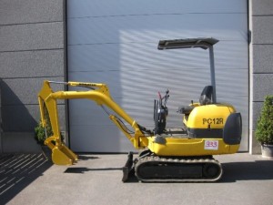
Komatsu PC12R-8, PC15R-8 Hydraulic Excavator Repair & Service Manual (Searchable & Printable PDF)

Komatsu PC12R-8, PC15R-8 Hydraulic Excavator Repair & Service Manual

Komatsu PC12R-8, PC15R-8 Hydraulic Excavator Repair & Service Manual (Searchable & Printable PDF)


MKMTSPC1215OPEK.PDF
Price: $19.99 USD

Shop Manual (WEBM000101) SAMPLE

Complete digital official shop manual contains service, maintenance, and troubleshooting information for the Komatsu PC12R-8, PC15R-8 Hydraulic Excavator. Diagnostic and repair procedures are covered in great detail to repair, maintain, rebuild, refurbish or restore your vehicle like a professional mechanic in local service/repair workshop. This cost-effective quality manual is 100% complete and intact as should be without any missing pages. It is the same factory shop manual used by dealers that guaranteed to be fully functional to save your precious time.

This manual for Komatsu PC12R-8, PC15R-8 Hydraulic Excavator is divided into different sections. Each section covers a specific component or system and, in addition to the standard service procedures, includes disassembling, inspecting, and assembling instructions. A table of contents is placed at the beginning of each section. Pages are easily found by category, and each page is expandable for great detail. It is in the cross-platform PDF document format so that it works like a charm on all kinds of devices. You do not need to be skilled with a computer to use the manual.

“Shop Manual (WEBM000101).pdf”
324 pages
PC12R-8, PC15R-8 HYDRAULIC EXCAVATOR
PC12R-8 F22426 in poi
PC15R-8 F31605 in poi

“Operation & Maintenance Manual (WEAM002702).pdf”
208 pages
PC12R-8, PC12R-8 HS, PC15R-8, PC15R-8 HS HYDRAULIC EXCAVATOR
SN: PC12R-8 – F31493 and up, PC12R-8 HS – F31493 and up, PC15R-8 – F22262 and up, PC15R-8 HS – F22262 and up

Buy the best manual on the Internet from responsible merchant and get instant download without surprise.

INSTANT Delivery: A download link will be sent to you instantly after payment. Simply click on the link and save it to your computer. You can use this Manual as long as you wish with no restrictions.

PRINTABLE with Diagrams: Just print the manual out and start to work. You can also use the manual with your laptop in your garage.

Customer SATISFACTION: If there is any problem, just drop a quick email. Within hours the issue shall be taken care of.

REFUND Policy: We sell high quality products only. In case there is any problem with your purchase, a replacement link will be sent to you. If we are at fault, you get 100% refund.

EXCERPT:
2.2.1 GENERAL SAFETY RULES
2.2.2 SAFETY DEVICES AND GUARDS
2.2.3 CLOTHING AND PERSONAL PROTECTION
ITEMS
• Only trained and authorized personnel can use the machine and perform maintenance operations.
• Follow all the safety rules, precautions and instructions when using the machine or performing maintenance operations.
• When working with other operators or when the work site is often occupied by other operators, make sure that
everyone knows and understands all the agreed signals and, in any case, that everyone works in such a way as
to be able to see the machine and to be visible to the operator.
• Make sure that all the guards and covers are in the correct position. Have guards and covers changed or repaired if damaged. Neither use the machine without guards, nor remove the guards when the engine is running.
• Always use the proper safety devices to lock the machine when parking and fasten the safety belt.
• For the safety devices, see “3.1 SAFETY LOCKS”.
• For the safety belt, see “3.5.6 SAFETY BELT”.
• Do not remove the safety devices and always keep them in good operating conditions.
• Any improper use of the safety devices may result in serious injuries or even death


MKMTSPC1215OPEK.PDF
Price: $19.99 USD

Posted on

Komatsu PC130-7 PC130-6K, PC150LGP-6K PC150-3, PC150LC-3 Excavator Repair & Service Manual (Searchable & Printable PDF)

Komatsu PC130-7 PC130-6K, PC150LGP-6K PC150-3, PC150LC-3 Excavator Repair & Service Manual

Komatsu PC130-7 PC130-6K, PC150LGP-6K PC150-3, PC150LC-3 Excavator Repair & Service Manual (Searchable & Printable PDF)


MKMTSPC130150OPEK.PDF
Price: $29.99 USD

Komatsu PC130-7 Shop Manual SAMPLE

Complete digital official shop manual contains service, maintenance, and troubleshooting information for the Komatsu PC130-7 PC130-6K, PC150LGP-6K PC150-3, PC150LC-3 Excavator. Diagnostic and repair procedures are covered in great detail to repair, maintain, rebuild, refurbish or restore your vehicle like a professional mechanic in local service/repair workshop. This cost-effective quality manual is 100% complete and intact as should be without any missing pages. It is the same factory shop manual used by dealers that guaranteed to be fully functional to save your precious time.

This manual for Komatsu PC130-7 PC130-6K, PC150LGP-6K PC150-3, PC150LC-3 Excavator is divided into different sections. Each section covers a specific component or system and, in addition to the standard service procedures, includes disassembling, inspecting, and assembling instructions. A table of contents is placed at the beginning of each section. Pages are easily found by category, and each page is expandable for great detail. It is in the cross-platform PDF document format so that it works like a charm on all kinds of devices. You do not need to be skilled with a computer to use the manual.

“Shop Manual (SEBM036301).pdf”
342 pages
PC130-7
70001 and up

“Shop Manual (EEBM001501).pdf”
730 pages
PC130-6K, PC150LGP-6K
K30001 and up, K35001 and up

“Operation & Maintenance (UEAM000602).pdf”
260 pages
PC130-6K, PC150LGP-6K HYDRAULIC EXCAVATOR
PC130-6K – K30001 and up, PC150LGP-6K – K35001 and up

“Shop Manual (SEBM021K0304).pdf”
559 pages
PC150-3, PC150LC-3 HYDRAULIC EXCAVATOR
3001 and up

Buy the best manual on the Internet from responsible merchant and get instant download without surprise.

INSTANT Delivery: A download link will be sent to you instantly after payment. Simply click on the link and save it to your computer. You can use this Manual as long as you wish with no restrictions.

PRINTABLE with Diagrams: Just print the manual out and start to work. You can also use the manual with your laptop in your garage.

Customer SATISFACTION: If there is any problem, just drop a quick email. Within hours the issue shall be taken care of.

REFUND Policy: We sell high quality products only. In case there is any problem with your purchase, a replacement link will be sent to you. If we are at fault, you get 100% refund.

EXCERPT:

Troubles which occur when solenoid power supply of governor and pump controller is
defective
~ The solenoid power supply (FB1-2) of the governor and pump controller is used by the controller to drive the solenoids and relays.
~ Accordingly, if the solenoid power supply is turned off, when the controller outputs the power to the solenoids or relays, the power is not supplied to any of the solenoids and relays and all or some of the following error codes are displayed simultaneously.
• [E213]: Disconnection in swing holding brake solenoid
• [E215]: Disconnection in 2-stage relief solenoid
• [E216]: Disconnection in travel speed shifting solenoid
• [E222]: Disconnection in LS-EPC solenoid
• [E223]: Disconnection in PC-EPC solenoid
~ If the above problems occur, check the related fuse (FB1-2) and inlet voltage of the governor and pump controller.
1) Disconnect connector C03 of the controller and connect a T-adapter to the wiring harness side.
2) Turn the starting switch ON.
3) Measure the voltage between each of pins (2) and (12) and each of pins (31), (32), and (33).
• Pins (2) and (3) are the power supply pins and pins (31), (32), and (33) are the ground pins.
• Pins (2) and (3) are the power supply and pins (31), (32), and (33) are the chassis ground.
• If the voltage is 20 – 30 V, it is normal.
~ Power supply connector (C03) of governor and pump controller


MKMTSPC130150OPEK.PDF
Price: $29.99 USD

Posted on

Komatsu PC650-5 PC650SE-5 PC650LC-5 PC710-5 PC710SE-5 Excavators Repair & Service Manual (734 pages Printable PDF)

Komatsu PC650-5 PC650SE-5 PC650LC-5 PC710-5 PC710SE-5 Excavators Repair & Service Manual

Komatsu PC650-5 PC650SE-5 PC650LC-5 PC710-5 PC710SE-5 Excavators Repair & Service Manual (734 pages Printable PDF)

PC650-710 Shop Manual SAMPLE


MKMTSPC650710OPEK.PDF
Price: $24.55 USD

Complete digital official shop manual contains service, maintenance, and troubleshooting information for the Komatsu PC650-5 PC650SE-5 PC650LC-5 PC710-5 PC710SE-5 Crawler Excavators. Diagnostic and repair procedures are covered in great detail to repair, maintain, rebuild, refurbish or restore your vehicle like a professional mechanic in local service/repair workshop. This cost-effective quality manual is 100% complete and intact as should be without any missing pages. It is the same factory shop manual used by dealers that guaranteed to be fully functional to save your precious time.

This manual for Komatsu PC650-5 PC650SE-5 PC650LC-5 PC710-5 PC710SE-5 Crawler Excavators is divided into different sections. Each section covers a specific component or system and, in addition to the standard service procedures, includes disassembling, inspecting, and assembling instructions. A table of contents is placed at the beginning of each section. Pages are easily found by category, and each page is expandable for great detail. It is in the cross-platform PDF document format so that it works like a charm on all kinds of devices. You do not need to be skilled with a computer to use the manual.

“Shop Manual (SEBM000607).pdf”
734 pages

MACHINE MODEL:
PC650-5
PC650SE-5
PC650LC-5
PC710-5
PC710SE-5

SERIAL NUMBER:
20001 and up
20001 and up
20001 and up
10001 and up
10001 and up

Buy the best manual on the Internet from responsible merchant and get instant download without surprise.

INSTANT Delivery: A download link will be sent to you instantly after payment. Simply click on the link and save it to your computer. You can use this Manual as long as you wish with no restrictions.

PRINTABLE with Diagrams: Just print the manual out and start to work. You can also use the manual with your laptop in your garage.

Customer SATISFACTION: If there is any problem, just drop a quick email. Within hours the issue shall be taken care of.

REFUND Policy: We sell high quality products only. In case there is any problem with your purchase, a replacement link will be sent to you. If we are at fault, you get 100% refund.

EXCERPT:

FUNCTION
When the OLSS mode is set to H mode, the discharge flow from the pump is controlled to the optimum by the command current from the controllerto match the change in the engine speed.
In S mode or L mode, and when the prolix switch is ON, the pump discharge flow is controlled to match the pump discharge pressure (load) by hydraulic sensing in accordance with a constant pump absorption torque.
* For details, see MACHINE CONTROL SYSTEM.

OPERATION
Because of the command current sent from the controller, solenoid push pin (10) moves, and piston (2) also moves. When this happens, it stops at a point where the sum of the force of spring (1) and the force of push pin (10) and the force of TVC output pressure Pe acting on piston (3) is in balance. At this point, the command current is small, so piston (2) is balanced at the bottom.
As a result, ports a and b are both almost completely open, and almost all the pressure oil from the charging pump output as TVC output pressure Pe.
For this reason, the pump discharge volume becomes the maximum.


MKMTSPC650710OPEK.PDF
Price: $24.55 USD

Posted on

Kobelco Mini Excavators SK09SR, SK15SR, SK15MSR, SK16, SK17, SK16MSR, SK20SR Repair & Service Manual (145 Printable PDF)

Kobelco Mini Excavators SK09SR, SK15SR, SK15MSR, SK16, SK17, SK16MSR, SK20SR Repair & Service Manual

Kobelco Mini Excavators SK09SR, SK15SR, SK15MSR, SK16, SK17, SK16MSR, SK20SR Repair & Service Manual (145MB Printable PDF)


MKBSK0920OPEK.PDF
Price: $29.99 USD

SK15MSR,SK16MSR SAMPLE

Complete digital official shop manual contains service, maintenance, and troubleshooting information for the Kobelco Mini Excavators SK09SR, SK15SR, SK15MSR, SK16, SK17, SK16MSR, SK20SR. Diagnostic and repair procedures are covered in great detail to repair, maintain, rebuild, refurbish or restore your vehicle like a professional mechanic in local service/repair workshop. This cost-effective quality manual is 100% complete and intact as should be without any missing pages. It is the same factory shop manual used by dealers that guaranteed to be fully functional to save your precious time.

This manual for Kobelco Mini Excavators SK09SR, SK15SR, SK15MSR, SK16, SK17, SK16MSR, SK20SR is divided into different sections. Each section covers a specific component or system and, in addition to the standard service procedures, includes disassembling, inspecting, and assembling instructions. A table of contents is placed at the beginning of each section. Pages are easily found by category, and each page is expandable for great detail. It is in the cross-platform PDF document format so that it works like a charm on all kinds of devices. You do not need to be skilled with a computer to use the manual.

MAKE: Kobelco
MODELS:
MINI EXCAVATORS
“SK09SR (S5PA0001E).pdf”
610 pages

“SK15MSR,SK16MSR (S5PF0002E).pdf”
616 pages

“SK15SR,SK20SR (S5PM0002E).pdf”
796

“SK16,SK17 (S5PF0004E).pdf”
630

Buy the best manual on the Internet from responsible merchant and get instant download without surprise.

INSTANT Delivery: A download link will be sent to you instantly after payment. Simply click on the link and save it to your computer. You can use this Manual as long as you wish with no restrictions.

PRINTABLE with Diagrams: Just print the manual out and start to work. You can also use the manual with your laptop in your garage.

Customer SATISFACTION: If there is any problem, just drop a quick email. Within hours the issue shall be taken care of.

REFUND Policy: We sell high quality products only. In case there is any problem with your purchase, a replacement link will be sent to you. If we are at fault, you get 100% refund.

EXCERPT:
1.3 OPERATION
(1) Hydraulic Piston Pump
Since the cylinder barrel of this piston pump is connected to the shaft with spline, it is rotated along with the shaft. The piston shoes which are incorporated in the cylinder barrel, follow to the rotation of the swash plate (slanted plate) resulting reciprocating movement that produces pumping action of suction and discharge depending upon the variation of the chamber volume.
This pump has even number of pistons so that the pump acts as two pumps with the same capacity in the one pump casing.
The valve plate, as shown in the Fig. 1-3, has two discharge grooves of outside (P1) and inside (P2). The every other piston chamber in the cylinder barrel is alternatively opened to either of discharge groove of outside (P1) or inside (P2), namely the same volume of discharge is independently exerted from P1 and P2 port. But suction groove is commonly used for both discharge grooves.
In this system, because of the even number of pistons, the same number of pistons is to be opened to the outside and inside of the valve plate. And all the pistons are identical with each other for the diameter, located on the same pitch circle, and sliding on the same swash plate.
Therefore, the discharge volume to outside (P1) and inside (P2) becomes equal.
Furthermore, because of only one swash plate, no difference is produced on the discharge volume to P1 and P2 eve.n though the slant angle of swash plate is varied due to variable control.


MKBSK0920OPEK.PDF
Price: $29.99 USD