Posted on

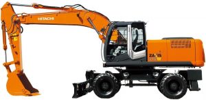
Hitachi ZX 200-5G, 200LC-5G, 210H-5G, 210LCH-5G, 210K-5G, 210LCK-5G Hydraulic Excavator Factory Service & Shop Manual


Pages from WDCDEN00 – Hitachi ZX 200-5G, 200LC-5G, 210H-5G, 210LCH-5G, 210K-5G, 210LCK-5G Hydraulic Excavator Workshop Manual

MHITZX210ZX220OPES.zip
Price: $29.99 USD

Complete workshop & service manual with electrical wiring diagrams for Hitachi ZX 200-5G, 200LC-5G, 210H-5G, 210LCH-5G, 210K-5G, 210LCK-5G Hydraulic Excavator. It’s the same service manual used by dealers that guaranteed to be fully functional and intact without any missing page.

This Hitachi ZX 200-5G, 200LC-5G, 210H-5G, 210LCH-5G, 210K-5G, 210LCK-5G Hydraulic Excavator service & repair manual (including maintenance, overhaul, disassembling & assembling, adjustment, tune-up, operation, inspecting, diagnostic & troubleshooting…) is divided into different sections. Each section covers a specific component or system with detailed illustrations. A table of contents is placed at the beginning of each section. Pages are easily found by category, and each page is expandable for great detail. The printer-ready PDF documents work like a charm on all kinds of devices.

FILELIST:
TODCDEN00 – Hitachi ZX 200-5G, 200LC-5G, 210H-5G, 210LCH-5G, 210K-5G, 210LCK-5G Hydraulic Excavator Technical Manual (Operational Principle).pdf
TTDCDEN00 – Hitachi ZX 200-5G, 200LC-5G, 210H-5G, 210LCH-5G, 210K-5G, 210LCK-5G Hydraulic Excavator Technical Manual (Troubleshooting).pdf
TTDCDEN00 (attach to) – Hitachi ZX 200-5G, 330-5G class Excavator Electrical Wiring Digram.pdf
WDCDEN00 – Hitachi ZX 200-5G, 200LC-5G, 210H-5G, 210LCH-5G, 210K-5G, 210LCK-5G Hydraulic Excavator Workshop Manual.pdf

EXCERPT:
SECTION AND GROUP CONTENTS
WORKSHOP MANUAL
SECTION 1 GENERAL INFORMATION
Group 1 Precautions for Disassembling and Assembling
Group 2 Tightening
Group 3 Painting
Group 4 Bleeding Air
Group 5 Pressure Release Procedure
Group 6 Preparation
SECTION 2 MAINTENANCE STANDARD
Group 1 Upperstructure
Group 2 Undercarriage
Group 3 Front Attachment
SECTION 3 UPPERSTRUCTURE
Group 1 Cab
Group 2 Counterweight
Group 3 Main Frame
Group 4 Engine
Group 6 Hydraulic Oil Tank
Group 7 Fuel Tank
Group 8 Pump Device
Group 9 Control Valve
Group 10 Swing Device
Group 11 Pilot Valve
Group 12 Solenoid Valve
Group 13 Signal Control Valve
SECTION 4 UNDERCARRIAGE
Group 1 Swing Bearing
Group 2 Travel Device
Group 3 Center Joint
Group 4 Track Adjuster
Group 5 Upper and Lower Rollers
Group 6 Track
SECTION 5 FRONT ATTACHMENT
Group 1 Front Attachment
Group 2 Cylinder

SECTION 1 GENERAL
Group 5 Pressure Release Procedure
Hydraulic Circuit Pressure Release Procedure
Release any remaining pressure as follows before removing/installing the front attachment.
1. Set pilot shut-off lever (1) to the UNLOCK position.
2. Turn engine stop switch (2) ON.
NOTE: Perform step 1 and step 2, and set the key switch to the START position. Although the starter rotates, the engine does not start.
IMPORTANT: Battery will deplete. Operate the key switch for short period.
3. With the key switch set in the START position, operate the control lever in order to release any pressure in the hydraulic circuit 4 to 5 times.
4. Return pilot shut-off lever (1) to the LOCK position.
5. Turn engine stop switch (2) OFF.

Posted on

Hitachi ZAXIS 210W/220W Wheeled Excavator Factory Service & Shop Manual


Pages from Hitachi ZX210W Wheeled Excavator Workshop Manual

MHITZX210W220WOPES.zip
Price: $29.99 USD

Complete workshop & service manual with electrical wiring diagrams for Hitachi ZAXIS 210W-3, ZAXIS 220W-3 Wheeled Excavator. It’s the same service manual used by dealers that guaranteed to be fully functional and intact without any missing page.

This Hitachi ZAXIS 210W-3, ZAXIS 220W-3 Wheeled Excavator service & repair manual (including maintenance, overhaul, disassembling & assembling, adjustment, tune-up, operation, inspecting, diagnostic & troubleshooting…) is divided into different sections. Each section covers a specific component or system with detailed illustrations. A table of contents is placed at the beginning of each section. Pages are easily found by category, and each page is expandable for great detail. The printer-ready PDF documents work like a charm on all kinds of devices.

FILELIST:
TTCJBE00 – Hitachi ZAXIS 210W-3, 220W-3 Wheeled Excavator Technical Manual (Troubleshooting).pdf
Hitachi ZX210W Wheeled Excavator Workshop Manual.pdf
TOCJBE00SP – ZX210W-3, ZX220W-3 Wheeled Excavator Technical Manual (Operational Principle).pdf
WCJBE00SP – Hitachi ZX210W-3, ZX220W-3 Hydraulic Excavator Workshop Manual.pdf
TOCJBE00 – Hitachi ZAXIS 210W-3, 220W-3 Wheeled Excavator Technical Manual (Operational Principle).pdf
WCJBE00 – Hitachi ZX 210W-3, 220W-3 Hydraulic Excavator Workshop Manual.pdf
TTCJBE00SP – Hitachi ZX210W-3, ZX220W-3 Wheeled Excavator Technical Manual (Troubleshooting).pdf
TTCDBE00 – Hitachi ZAXIS 210W Wheeled Excavator Technical Manual (Troubleshooting).pdf
TTCJBE00 (attach to) – Hitachi ZAXIS 140W-3, 170W-3, 190W-3, 210W-3, 220W-3 Electrical Wiring Diagram
EM4GB11 – Hitachi ZX220, 250, 310 Wheel Loader Operator’s Manual.pdf
EMCBBENOP31 – Hitachi ZAXIS 210W Scrap Handling Attachment Operator’s Manual.pdf

EXCERPT:
UNDERCARRIAGE / Swing Bearing
REMOVE AND INSTALL SWING BEARING
Before removing the swing bearing, the upperstructure must be removed first. For removal and installation of the upperstructure, refer to “Remove and Install Main Frame” section.
In this section, the procedure starts on the premise that the upperstructure has already been removed.
Removal
1. Put mating marks on inner race (1) of swing bearing (4) and chassis (2).

Posted on

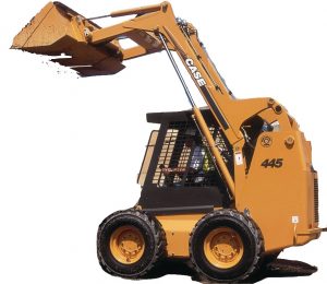
Case 435, 445, 445CT Series 3 Skid Steer/Compact Track Loader Factory Service & Shop Manual


Pages from 87634768 NA – Case 435, 445, 445CT Series 3 Skid Steer-Compact Track Loader Repair Manual


INSTANT DOWNLOAD


Complete workshop & service manual with electrical wiring diagrams for Case 435, 445, 445CT Series 3 Skid Steer/Compact Track Loader. It’s the same service manual used by dealers that guaranteed to be fully functional and intact without any missing page.

This Case 435, 445, 445CT Series 3 Skid Steer/Compact Track Loader service & repair manual (including maintenance, overhaul, disassembling & assembling, adjustment, tune-up, operation, inspecting, diagnostic & troubleshooting…) is divided into different sections. Each section covers a specific component or system with detailed illustrations. A table of contents is placed at the beginning of each section. Pages are easily found by category, and each page is expandable for great detail. The printer-ready PDF documents work like a charm on all kinds of devices.

87634768 NA – Case 435, 445, 445CT Series 3 Skid Steer/Compact Track Loader Repair Manual.pdf; 1,183 pages

EXCERPT:
POWER TRAIN – POWER COUPLING Fixed coupling
Pump drive -Visual inspection
1. Inspect the pump drive flange (6) for cracks or any other damage. Inspect the splines on the pump drive flange (6) for wear or any other damage. Use new parts as required.
2. Inspect the pump drive coupler hub (7) for cracks or any other damage. Inspect the splines on the inside and outside of the pump drive coupler hub (7) for wear or any other damage. Use new parts as required.
3. Inspect the engine adapter (4) for cracks or any other damage. Use new parts as required.


INSTANT DOWNLOAD


Posted on

Case WX148 Wheeled Excavator Factory Service & Shop Manual


Pages from 47500167 – Case WX148 Wheeled Excavator Service Manual

MCSWX148WOPEK.zip
Price: $29.99 USD

Complete workshop & service manual with electrical wiring diagrams for Case WX148 Wheeled Excavator. It’s the same service manual used by dealers that guaranteed to be fully functional and intact without any missing page.

This Case WX148 Wheeled Excavator service & repair manual (including maintenance, overhaul, disassembling & assembling, adjustment, tune-up, operation, inspecting, diagnostic & troubleshooting…) is divided into different sections. Each section covers a specific component or system with detailed illustrations. A table of contents is placed at the beginning of each section. Pages are easily found by category, and each page is expandable for great detail. The printer-ready PDF documents work like a charm on all kinds of devices.

FILELIST:
47500167 – Case WX148 Wheeled Excavator Service Manual.pdf

EXCERPT:
Contents
INTRODUCTION
Engine. . .10
[10.001] Engine and crankcase . . . 10.1
[10.202] Air cleaners and lines . . 10.2
[10.206] Fuel filters . . 10.3
[10.216] Fuel tanks . . 10.4
[10.254] Intake and exhaust manifolds and muffler . . 10.5
[10.400] Engine cooling system . . . 10.6
Transmission. . .21
[21.105] Powershift transmission lubrication system . . . 21.1
[21.113] Powershift transmission . . . 21.2
[21.135] Powershift transmission external controls. . . 21.3
[21.155] Powershift transmission internal components. . 21.4
Four-Wheel Drive (4WD) system . . .23
[23.314] Drive shaft. . 23.1
Front axle system . . .25
[25.100] Powered front axle . . 25.1
[25.102] Front bevel gear set and differential . . 25.2
[25.108] Final drive hub, steering knuckles, and shafts . . . 25.3
[25.122] Axle suspension control . . . 25.4
Rear axle system. . .27
[27.100] Powered rear axle. . . 27.1
[27.106] Rear bevel gear set and differential . . . 27.2
[27.120] Planetary and final drives . . . 27.3
Brakes and controls . . .33
[33.110] Parking brake or parking lock . . . 33.1
[33.202] Hydraulic service brakes . . 33.2
Hydraulic systems. . .35
[35.000] Hydraulic systems. . . 35.1
[35.102] Pump control valves. . . 35.2
[35.106] Variable displacement pump . . . 35.3
[35.300] Reservoir, cooler, and filters. . 35.4
[35.304] Combination pump units . . 35.5
[35.352] Hydraulic swing system . . . 35.6
[35.353] Hydraulic travel system . . . 35.7
[35.354] Hydraulic central joint . . 35.8
[35.357] Pilot system . . . 35.9
[35.359] Main control valve . . . 35.10
[35.360] Hammer and rotating bucket hydraulic system . . . 35.11
[35.703] Stabilizer hydraulic system. . . 35.12
[35.730] Positioning arm hydraulic system . . . 35.13
[35.736] Boom hydraulic system . . . 35.14
[35.737] Dipper hydraulic system. . . 35.15
[35.738] Excavator and backhoe bucket hydraulic system . . 35.16
[35.741] Dozer blade cylinders . . . 35.17
Frames and ballasting . . .39
[39.103] Swing ring assembly . . . 39.1
[39.129] Stabilizers . . 39.2
[39.140] Ballasts and supports . . 39.3
Steering. . .41
[41.101] Steering control . . 41.1
[41.106] Tie rods. . 41.2
[41.200] Hydraulic control components. . . 41.3
[41.216] Cylinders . . . 41.4
Wheels. . .44
[44.511] Front wheels. . . 44.1
Cab climate control . . .50
[50.200] Air conditioning. . . 50.1
Electrical systems . . .55
[55.000] Electrical system . . . 55.1
[55.010] Fuel injection system. . . 55.2
[55.012] Engine cooling system . . . 55.3
[55.014] Engine intake and exhaust system. . . 55.4
[55.015] Engine control system. . 55.5
[55.020] Transmission speed sensors. . . 55.6
[55.031] Parking brake electrical system . . . 55.7
[55.036] Hydraulic system control . . 55.8
[55.050] Heating, Ventilation, and Air-Conditioning (HVAC) control system. . 55.9
[55.100] Harnesses and connectors. . . 55.10
[55.110] Electrical rotary joint. . 55.11
[55.302] Battery. . . 55.12
[55.404] External lighting . . . 55.13
[55.425] Boom, dipper, and bucket control system . . . 55.14
[55.512] Cab controls. . . 55.15
[55.514] Cab lighting . . . 55.16
[55.525] Cab engine controls . . 55.17
[55.530] Camera. . . 55.18
[55.640] Electronic modules . . . 55.19
Booms, dippers, and buckets . . .84
[84.100] Bucket . . . 84.1
[84.910] Boom . . . 84.2
Dozer blade and arm. . .86
[86.110] Dozer blade . . . 86.1
Platform, cab, bodywork, and decals . . .90
[90.118] Protections and footboards. . . 90.1
[90.120] Mechanically-adjusted operator seat. . 90.2
[90.150] Cab. . . 90.3

Hydraulic systems – Main control valve
Oil flow pump P1
The oil flows through port P1 into the main valve and then to the primary pressure-limiting valve of pump P1.
The oil flows through the two parallel channels P1 and P01 to the control spools and to the valves.
Channel P1 directs the oil flow through a valve of the bucket parallel circuit to the bucket control spool.
Channel P01 directs the oil flow to the travel spool, from where a branch-off leads to a load holding valve. The load-holding valve opens and the oil is available at the travel spool, ready to be recalled. The oil flow by-passes the stabilizer spool and reaches the boom spool. A branch-off ahead of the spool directs the oil flow also through another load holding valve to the boom spool. The oil flows then to the bucket spool. The oil is then available to the bucket spool via a load-holding valve. The oil flow reaches then the dipper spool. Also here a branch-off delivers oil to the dipper spool through a load holding valve. Two parallel channels P2 and P02 direct the oil flow through the main valve.
Oil flow pump P2

Posted on

Hitachi ZAXIS 170W-3, 190W-3 Factory Service & Shop Manual


Pages from TOCGBE00 – Hitachi ZAXIS 170W-3, 190W-3 Wheeled Excavator Technical Manual (Operationel Principle)

MHITZX170W190WOPES.zip
Price: $29.99 USD

Complete workshop & service manual with electrical wiring diagrams for Hitachi ZAXIS 170W-3, 190W-3 Wheeled Excavator. It’s the same service manual used by dealers that guaranteed to be fully functional and intact without any missing page.

This Hitachi ZAXIS 170W-3, 190W-3 service & repair manual (including maintenance, overhaul, disassembling & assembling, adjustment, tune-up, operation, inspecting, diagnostic & troubleshooting…) is divided into different sections. Each section covers a specific component or system with detailed illustrations. A table of contents is placed at the beginning of each section. Pages are easily found by category, and each page is expandable for great detail. The printer-ready PDF documents work like a charm on all kinds of devices.

FILELIST:
TTCGBE00 – Hitachi ZAXIS 170W-3, 190W-3 Wheeled Excavator Technical Manual (Troubleshooting).pdf
TTLA0721ZX – Hitachi ZAXIS 170W-3, 190W-3 Wheeled Excavator Training Text (Operationel Principle).pdf
TTLA0722ZX – Hitachi ZAXIS 170W-3, 190W-3 Wheeled Excavator Training Text (Performance Test Troubleshooting).pdf
WCGBE00 – Hitachi ZX 170W-3, 190W-3 Hydraulic Excavator Workshop Manual.pdf
TOCGBE00 – Hitachi ZAXIS 170W-3, 190W-3 Wheeled Excavator Technical Manual (Operationel Principle).pdf
TTCEBE00 (attach to) – Hitachi ZAXIS 140W-3, 170W-3, 190W-3, 210W-3, 220W-3 Electrical Wiring Diagram (e-Cabinet+only).pdf
TTCEBE00 (attach to) – Hitachi ZAXIS 140W-3, 170W-3, 190W-3, 210W-3, 220W-3 Electrical Wiring Diagram updated+information_7pages(070618).pdf
ENMLBANA13 – Hitachi ZAXIS 190W-5N, 230W-5N Wheeled Excavator Operator’s Manual.pdf
TTCEBR00_TTCGBR00_TTCJBR00 – Hitachi ЭЛЕКТРИЧЕСКАЯ СХЕМА ZAXIS140W-3_170W-3_190W-3_210W-3_220W-3 (ПО ЗАКАЗУ).pdf
TTCEBR00_TTCGBR00_TTCJBR00 – Hitachi ЭЛЕКТРИЧЕСКАЯ СХЕМА ZAXIS140W-3, 170W-3, 190W-3, 210W-3, 220W-3 (СТАНДАРТНАЯ).pdf

EXCERPT:
SECTION 1 GENERAL
Group 1 Specification
Group 2 Component Layout
Group 3 Component Specifications
SECTION 2 SYSTEM
Group 1 Controller
Group 2 Control System
Group 3 ECM System
Group 4 Hydraulic System
Group 5 Electrical System
SECTION 3 COMPONENT OPERATION
Group 1 Pump Device
Group 2 Swing Device
Group 3 Control Valve
Group 4 Pilot Valve
Group 5 Electric Lever
Group 6 Transmission
Group 7 Axle
Group 8 Travel Motor
Group 9 Signal Control Valve
Group 10 Steering Valve
Group 11 Brake Valve
Group 12 Others (Upperstructure)
Group 13 Others (Undercarriage)
TECHNICAL MANUAL (Troubleshooting)
SECTION 4 OPERATIONAL PERFORMANCE TEST
Group 1 Introduction
Group 2 Standard
Group 3 Engine Test
Group 4 Excavator Test
Group 5 Component Test
SECTION 5 TROUBLESHOOTING
Group 1 Diagnosing Procedure
Group 2 Monitor Unit
Group 3 Dr. ZX
Group 4 ICF
Group 5 Component Layout
Group 6 Troubleshooting A
Group 7 Troubleshooting B
Group 8 Electrical System Inspection

COMPONENT OPERATION / Pump Device
OUTLINE
The pump device consists of transmission (9), main pump (pump 1 (1), pump 2 (2)), pilot pump (5) and steering pump (6).
The engine output is transmitted to transmission (9) via coupling (13). After being distributed by the gear, the engine power drives pump 1 (1), 2 (2), pilot pump (5) and steering pump (6). The reduction gear ratios of the main pump, pilot pump (5) and steering pump
(6) are 1:1. Transmission (9) is lubricated with engine oil.
The main pump is a bent-axis type variable displacement axial plunger pump. Pump 1 (1) and pump 2 (2) are integrated as two units in one housing.
Pilot pump (5) and steering pump (6) are gear pumps. Pump delivery pressure sensors (3, 4) and pump control pressure sensors (7, 8) are installed in order to control the pump and valve. (Refer to the SYSTEM / Control System group.)