Posted on

John Deere Compact Utility Tractor 2025R Service Technical Manual (TM127019)

John Deere Compact Utility Tractor 2025R Service Technical Manual (TM127019)

INSTANT DOWNLOAD
tm127019 – Compact Utility Tractor 2025R Technical Manual.pdf

Complete Diagnostics Test Repair Service manual for John Deere Compact Utility Tractor 2025R, with all the shop information to maintain, diagnostic, repair, sercvice like professional mechanics.

John Deere Compact Utility Tractors 2025R workshop Diagnosis Operation Repair Service Technical Manual (All Inclusive) includes:
* Numbered table of contents easy to use so that you can find the information you need fast.
* Detailed sub-steps expand on repair procedure information
* Numbered instructions guide you through every repair procedure step by step.
* Troubleshooting and electrical service procedures are combined with detailed wiring diagrams for ease of use.
* Notes, cautions and warnings throughout each chapter pinpoint critical information.
* Bold figure number help you quickly match illustrations with instructions.
* Detailed illustrations, drawings and photos guide you through every procedure.
* Enlarged inset helps you identify and examine parts in detail.

Total Pages: 1,112 pages
File Format: PDF (bookmarked, ToC, Searchable, Printable, high quality)
Language: English

MAIN SECTIONS
 Foreword
   Introduction
      Thank You for Purchasing a John Deere Product
      Using Your Operator’s Manual
      Special Messages
      Attachments for Your Machine
      Machine Use
   Product Identification
      Record Identification Numbers
      Cab Serial Number
   Safety Labels
      Safety Label Location
      Pictorial Safety Signs
      CAUTION – LVU11641
      WARNING – LVU23360
      WARNING – LVU802017
      WARNING KEEP RIDERS OFF – LVU13286
   Safety
      Recognize Safety Information
      Understand Signal Words
      Follow Safety Instructions
      Prepare for Emergencies
      Wear Protective Clothing
      Protect Against Noise
      Handle Fuel Safely-Avoid Fires
      Fire Prevention
      In Case of Fire
      Avoid Static Electricity Risk When Refueling
      Use Foldable ROPS and Seat Belt Properly
      Stay Clear of Rotating Drivelines
      Use Steps and Handholds Correctly
      Read Operator Manuals for ISOBUS Implements
      Use Seat Belt Properly
      Vibration
      Operating the Tractor Safely
      Avoid Backover Accidents
      Limited Use in Forestry Operation
      Operating the Loader Tractor Safely
      Keep Riders Off Machine
      Passenger Seat
      Use Safety Lights and Devices
      Towing Trailers/Implements Safely (Mass)
      Use Caution On Slopes and Uneven Terrain
      Freeing a Mired Machine
      Avoid Contact with Agricultural Chemicals
      Handle Agricultural Chemicals Safely
      Handling Batteries Safely
      Avoid Heating Near Pressurized Fluid Lines
      Remove Paint Before Welding or Heating
      Handle Electronic Components and Brackets Safely
      Practice Safe Maintenance
      Avoid Hot Exhaust
      Clean Exhaust Filter Safely
      Work In Ventilated Area
      Support Machine Properly
      Prevent Machine Runaway
      Park Machine Safely
      Transport Tractor Safely
      Service Cooling System Safely
      Service Accumulator Systems Safely
      Service Tires Safely
      Service Front-Wheel Drive Tractor Safely
      Tightening Wheel Retaining Bolts/Nuts
      Avoid High-Pressure Fluids
      Do Not Open High-Pressure Fuel System
      Store Attachments Safely
      Dispose of Waste Properly
   Operating Controls
      Operator Station Controls
      Floor Panel Controls
   Operating
      Daily Operating Checklist
      Avoid Damage to Plastic and Painted Surfaces
      Cab Classification According to EN15695-1 (for Application of
Crop Protection Chemicals and Liquid Fertilizer)
      Adjusting Seat
      Using Seat Belt
      Using Light Switch
      Using Key Switch
      Using Horn
      Using Instrument Panel
      Using Turn Signal Switch
      Using Hazard Warning Light Switch
      Testing Safety Systems
      Testing the Neutral Start Switch
      Testing the Rear Power-Take-Off/Reverse Implement Option (PTO/RIO)
Switch
      Testing the Seat Switch
      Testing Mid-PTO/Seat Switch Interface
      Testing Rear PTO/Park Brake Interface
      Testing Reverse Implement Option (RIO)
      Using Brake Pedals
      Using Park Brake
      Using Throttle
      Using Fuel Shut-Off Valve
      Starting the Engine
      Cold Weather Starting Aids
      Warming and Idling the Engine
      Starting a Stalled Engine
      Stopping Machine
      Operating the Hydrostatic Transmission
      Using Reverse Implement Option (RIO)
      Using Cruise Control
      Using Differential Lock (Traction Assist)
      Using Mechanical Front Wheel Drive (MFWD)
      Using the Power-Take-Off (PTO) Safely
      Using Rear and Mid PTO (Operator on Seat)
      Using Rear PTO (Operator Off Seat)
      Using Drawbar Hitch
      Using 3-Point Hitch (2025R)
      Using 3-Point Hitch (2027R and 2032R)
      Using Optional iMatch™ Quick-Attach Hitch System
      Connecting Implement Hydraulic Hoses
      Using Hydraulic Dual Selective Control Valve (SCV) (2025R)
      Using Dual Selective Control Valve Lever (2027R and 2032R)
      Using Selective Control Valve (SCV) Lock Lever
      Locking Out Dual SCV Regen Function
      Using Mower Height Control Knob (2025R)
      Operating Cab (If Equipped)
      Ballasting Machine
      Transporting Machine on Trailer
      Transporting Machine
      Towing Loads
      Using Safety Chain
      Raising and Lowering Roll-Over Protective Structure (ROPS)
      Roll-Over Protective Structure Label
      Front Loader Installation
   Replacement Parts
      Service Literature
      Parts
      Part Numbers
   Service Intervals
      Servicing Your Machine
      As Needed
      After First 10 Hours
      Every 10 Hours or Daily
      After First 50 Hours
      Every 50 Hours
      Every 200 Hours
      Every 400 Hours
      Every 600 Hours
      Annually
      Every 1200 Hours
      Every Two Years or 2000 Hours
      Every Six Years or 6000 Hours
   Service Lubrication
      Grease
      Lubricating Machine Grease Fittings
      Lubricating Hydraulic Selective Control Valve (SCV) Linkage
      Lubricating Hood Latch
      Lubricating 3-Point Hitch
   Service Engine
      Engine Emissions Information
      Avoid Fumes
      Engine Oil
      Checking Engine Speeds
      Checking Engine Oil Level
      Changing Engine Oil and Filter
      Cleaning Dust Unloading Valve
      Servicing Air Filter Elements
      Checking Air Filter Intake Hoses and Clamps
      Service Cooling System Safely
      Recommended Engine Coolant
      Servicing Cooling System
      Checking Radiator Hoses and Clamps
      Cleaning Radiator Cooling Screen and Fins
      Servicing the Alternator Belt
      Checking and Cleaning Fuel Filter Sediment Bowl and Replacing
Filter
      Fuel Injection Pump
      Fuel Injection Nozzles
      Cleaning Front Grille Screens
   Service Transmission
      Gear Case Oil
      Checking Front Axle Oil Level
      Changing Front Axle Oil
      Transmission and Hydraulic Oil
      Checking Transmission Oil Level
      Changing Transmission Oil and Filter (2025R)
      Changing Transmission Oil and Filter (2027R and 2032R)
   Service Electrical
      WARNING:
      Service the Battery Safely
      Checking Battery Electrolyte Level
      Removing and Installing Battery
      Cleaning Battery and Terminals
      Using Booster Battery
      Replacing Headlight Bulb (2025R)
      Replacing Headlight Bulb (2027R and 2032R)
      Replacing Light Bulbs
      Replacing Fuses (2025R)
      Replacing Fuses (2027R and 2032R)
   Service Miscellaneous
      Using Proper Fuel (Diesel)
      Filling Fuel Tank
      Lifting Points for Jacking up the Tractor
      Raising and Lowering Hood
      Checking Wheel Bolts and Hardware
      Removing and Installing Wheels
      Checking Tire Pressure
      Selecting Front Tire Rolling Direction
      Cleaning Plastic Surfaces
      Cleaning and Repairing Metal Surfaces
   Troubleshooting
      Using Troubleshooting Chart
      Engine
      Electrical System
      Machine
      Brakes
      Steering
   Storage
      Storing Safety
      Preparing Machine for Storage
      Preparing Fuel and Engine For Storage
      Removing Machine From Storage
   Specifications
      Engine
      Drivetrain
      Electrical System
      Front Wheels and Tires
      Rear Wheels and Tires
      Front Tire Inflation Pressures (Maximum)
      Rear Tire Inflation Pressures (Maximum)
      Tire Combinations (2025R)
      Tire Combinations (2027R and 2032R)
      Tire Loads
      Weight Specifications
      Fluid Capacities
      Ground Speeds
      Dimensions
      Weight
      Sound Level (all)
      PTO Options (all)
      3-Point Hitch
      Coupling Devices (all)
      Torque Values – Inch Fastener Hardware
      Torque Values – Metric Hardware
   Declaration of Conformity
      EC Declaration of Conformity
   John Deere Quality Statement
      John Deere Quality
   Service Record
      Record Service Dates

tm127019 – Compact Utility Tractor 2025R

Table of Contents

Foreword

Section 10: Safety

Group 05: Safety

Recognize Safety Information

Understand Signal Words

Replace Safety Signs

Handle Fluids Safely—Avoid Fires

Prepare for Emergencies

Prevent Battery Explosions

Prevent Acid Burns

Wear Protective Clothing

Avoid High-Pressure Fluids

Avoid Heating Near Pressurized Fluid Lines

Service Machines Safely

Use Proper Tools

Park Machine Safely

Support Machine Properly

Use Proper Lifting Equipment

Work in Clean Area

Protect Against High Pressure Spray

Illuminate Work Area Safely

Work In Ventilated Area

Remove Paint Before Welding or Heating

Avoid Harmful Asbestos Dust

Service Tires Safely

Stay Clear of Rotating Drivelines

Service Cooling System Safely

Dispose of Waste Properly

Handle Chemical Products Safely

Live With Safety

Section 20: Specifications and Information

Group 05: General Specifications

Metric Bolt and Screw Torque Values

Unified Inch Bolt and Screw Torque Values

Metric Cap Screw Torque Values—Grade 7

Gasket Sealant Application

Service Recommendations For Flat Face O-Ring Seal Fittings

Service Recommendations for O-Ring Boss Fittings

Group 10: Fuel and Lubricants

Diesel Fuel

Handling and Storing Diesel Fuel

Diesel Engine Oil

Diesel Engine Break-In Oil

Alternative and Synthetic Lubricants

Lubricant Storage

Mixing of Lubricants

Grease

Transmission and Hydraulic Oil

Heavy Duty Diesel Engine Coolant

Group 15: Serial Number Locations

Serial Numbers

Machine Product Identification Number

Engine Serial Number

Section 30: Engine – Diesel

Group 05: Specifications

General Specifications

Operational Tests

Tests and Adjustment Specifications

Repair Specifications

Torque Specifications

Service Equipment and Tools

Special Tools

Other Materials

Group 10: Theory of Operation

Cooling System Operation

Lubrication System Operation

Fuel System Theory of Operation

Air System Theory of Operation

Group 15: Component Location

Engine

Fuel System

Group 20: Diagnostics

Starting Problems

Low Engine Output

Exhaust Abnormal Under Load

Engine Runs Rough

Excessive Fuel Consumption

Lubricating Oil

Temperature Problems

Low Compression

Engine Diagnostic Table

Group 25: Tests and Adjustments

Cylinder Compression Test

Throttle Cable Adjustment

Slow Idle Adjustment

Valve Clearance Adjustment

Valve Lift Check

Fuel Injection System Tests

Fuel Injection Nozzle Test

Injection Pump Static Timing Check

Injection Pump Timing (EPA Engines)

Thermostat Test

Fan/Alternator Belt Adjustment

Radiator Bubble Test

Cooling System Pressure Test

Radiator Cap Pressure Test

Engine Oil Pressure Test

Fuel Transfer Pump Pressure Test

Fuel Pump Flow Test

Fuel System Leakage Test

Bleed Fuel System

Group 30: Repair

Fan/Alternator Belt Removal and Installation

Muffler Removal and Installation

Exhaust Manifold Removal and Installation

Rocker Arm Cover Removal and Installation

Radiator Removal and Installation

Engine Removal and Installation

Rocker Arm and Push Rods

Cylinder Head Removal and Installation

Cylinder Head Recondition

Crankshaft Oil Seals

Timing Gear Cover

Camshaft End Play Check

Timing Gear Backlash Check

Idler Gear

Camshaft Followers

Camshaft

Oil Pan and Strainer

Connecting Rod Side Play Check

Crankshaft End Play Check

Connecting Rod Bearing Clearance Check

Crankshaft Main Bearing Clearance Check

Piston-To-Cylinder Head Clearance

Piston and Connecting Rod Repair

Cylinder Bore

Crankshaft and Main Bearings

Flywheel Removal and Installation

Engine Back Plate

Timing Gear Housing

Oil Pump

Coolant Temperature Switch

Thermostat Removal and Installation

Water Pump

Fuel Transfer Pump

Fuel Injection Nozzle

Fuel Injection Pump

Fuel Shutoff Solenoid Removal and Installation

Fuel Control and Governor Linkage Removal and Installation

Fuel Filter Assembly Removal and Installation

Fuel Filter Removal and Installation

Group 35: Starting Motor

Starting Motor Removal and Installation

Starting Motor Disassembly and Assembly

Starting Motor Inspection and Test

Starting Motor Gear Train

Starting Motor Solenoid

Alternator

Section 40: Electrical

Group 05: General Information

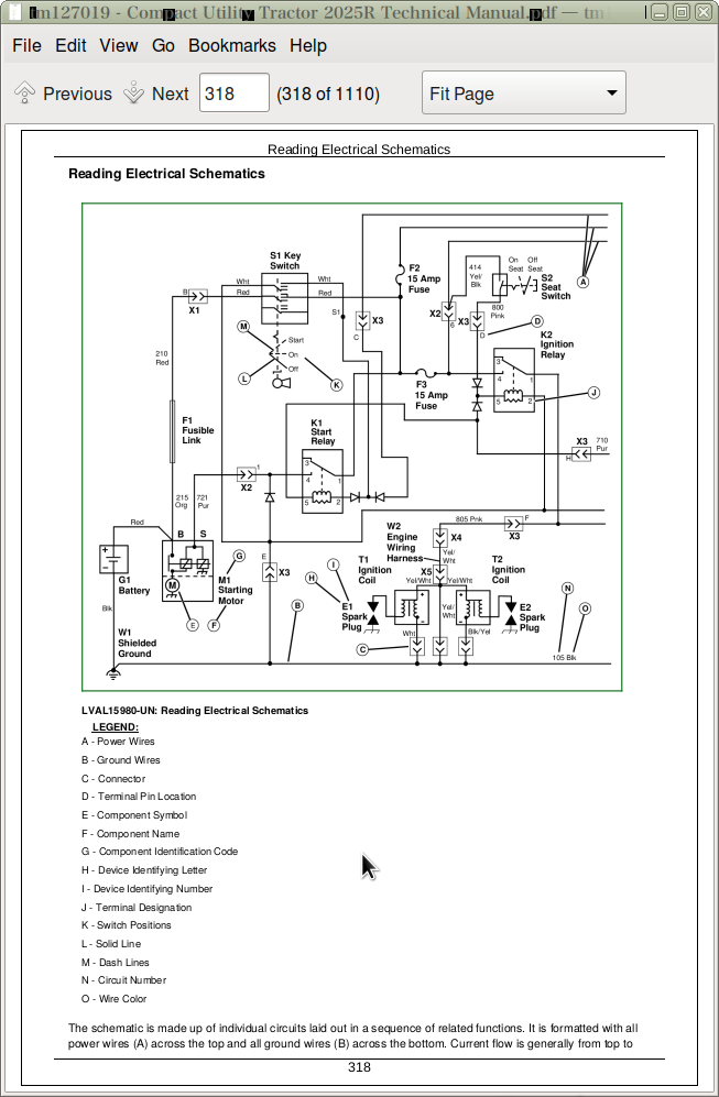
Reading Electrical Schematics

Theory Of Operation Information

Diagnostic Information

Wire Color Abbreviation Chart

Common Circuit Tests

Conductors for 12 Volt Circuits

Group 10: Specifications

System Specifications

Service Equipment and Tools

Other Materials

Group 15: Component Location

Electrical Components

Group 20: System Schematics

Schematic and Wiring Harness Legend

Electrical Schematic (1 of 6)

W1 Main Wiring Harness (1 of 4)

W2 Power Supply Wiring Harness

W3 Battery Cable Wiring Harness

W1 Main Wiring Harness Color Codes

W2 Power Supply Wiring Harness Color Codes

W3 Battery Cable Wiring Harness Color Codes

Group 25: Diagnostics & Operation

Power Circuit Operation

Power Circuit Electrical Schematic

Power Circuit Diagnosis

Cranking Circuit Operation

Cranking Circuit Electrical Schematic

Cranking Circuit Diagnosis

Engine Preheater Circuit Operation

Engine Preheater Circuit Electrical Schematic

Engine Preheater Circuit Diagnosis

Fuel Supply Operation

Engine Shutoff Circuit Operation

Fuel Supply/Engine Shutoff Circuit Electrical Schematic

Fuel Supply Diagnosis

Engine Shutoff Circuit Diagnosis

Charging Circuit Operation

Charging Circuit Electrical Schematic

Charging Circuit Diagnosis

PTO Circuit Operation

PTO Circuit Electrical Schematic

PTO Circuit Diagnosis

Control Panel Circuit Operation

Control Panel Circuit Electrical Schematic

Control Panel Circuit Diagnosis

Light Switch Circuit Operation

Light Switch Circuit Electrical Schematic

Light Switch Circuit Diagnosis

Turn Signal Circuit Operation

Turn Signal Circuit Electrical Schematic

Turn Signal Circuit Diagnosis

Group 30: Tests and Adjustments

Ground Circuit Test

Battery Voltage and Specific Gravity Test

Battery – Charge

Battery – Load Test

Unregulated Voltage Output Test

Stator Resistance Test

Unregulated Amperage Test – 55 Amp

Regulated Amperage and Voltage Test

Regulator/Rectifier Test

Starting Motor Solenoid Test

No-Load Amperage Draw and RPM Test

Starting Motor Amperage Draw Test

Engine Coolant Temperature Sensor Test

Engine Oil Pressure Switch Test

Glow Plug Test

Diode Test

Fuse Test

Control Panel Light Test

Light Switch Test

Fuel Pull-in Relay Test

Relay Test

Engine Preheater Relay Test

Key Switch Test

Seat Switch Test

Transmission Neutral Switch Test

Turn Signal Switch Test

Position Lights Switch Test

Hazard Lights Switch Test

Rear PTO Switch Test

PTO Switch Test

PTO Solenoid Test

Fuel Shutoff Solenoid Test

Fuel Gauge Sensor Test

PTO Solenoid Test

Parking Brake Switch Test and Adjustment

Brake Switch Test

Reverse Implement Option (RIO)Test

Section 45: Export Electrical

Group 05: Specifications

System Specifications

Service Equipment and Tools

Other Materials

Group 10: Component Location

Electrical Components

Group 15: System Schematics

Schematic and Wiring Harness Legend

Electrical Schematic (1 of 6)

W1 Main Wiring Harness (1 of 4)

W2 Power Supply Wiring Harness

W3 Battery Cable Wiring Harness

W4 Engine Wiring Harness

Y2 Fuel Shutoff Solenoid

W1 Main Wiring Harness Color Codes

W2 Power Supply Wiring Harness Color Codes

W3 Battery Cable Wiring Harness Color Codes

Group 20: Diagnostics and Operation

Power Circuit Operation

Power Circuit Electrical Schematic

Power Circuit Diagnosis

Cranking Circuit Operation

Cranking Circuit Electrical Schematic

Cranking Circuit Diagnosis

Engine Preheater Circuit Operation

Engine Preheater Circuit Electrical Schematic

Engine Preheater Circuit Diagnosis

Fuel Supply Operation

Engine Shutoff Circuit Operation

Fuel Supply/Engine Shutoff Electrical Schematic

Fuel Supply Diagnosis

Engine Shutoff Circuit Diagnosis

Charging Circuit Operation

Charging Circuit Electrical Schematic

Charging Circuit Diagnosis

PTO Circuit Operation

PTO Circuit Electrical Schematic

PTO Circuit Diagnosis

Control Panel Circuit Operation

Control Panel Circuit Electrical Schematic

Control Panel Circuit Diagnosis

Marker, Head, and Brake Light Circuit Operation

Marker, Head, and Brake Light Circuit Electrical Schematic

Marker, Head, and Brake Light Circuit Diagnosis

Hazard Lights and Turn Signal Lights Circuit Operation

Hazard Lights and Turn Signal Lights Circuit Electrical Schematic

Hazard Lights and Turn Signal Lights Circuit Diagnosis

Section 50: Power Train – Hydrostatic

Group 05: Specifications

Specifications

Essential or Recommended Tools

Service Equipment and Tools

Other Material

Group 10: Component Location

Drive Pedals and Linkage Components

Swash Plate and Control Arm Components

Center Case and Pumps Components

Differential Front Cover Components

Countershaft and Reduction Shaft Components

Differential Carrier Components

Rear Axle and Final Drive Components

PTO Clutch and Brake Shaft Components

PTO Drive and Output Shafts Components

Mid PTO Shaft Components

MFWD Front Drive Shaft Components

MFWD Front Axle Housing Components

MFWD Front Gear Case Components

MFWD Front Spindle and Final Drive Gears Components

Group 15: Theory of Operation

Drive Train Range Drive Gears

Rear and Mid PTO Drive

MFWD Drive Gears

Group 20: Diagnostics

Transmission Troubleshooting

Power Train Checks

Group 25: Tests and Adjustments

Hydrostatic High Pressure Relief Test

Charge Pump Pressure Test

Neutral Adjustment

Reverse Implement Sensor Removal and Installation

Reverse Implement Sensor Adjustment

Group 30: Repair

Transaxle Removal and Installation

Hydrostatic Pump and Motor Removal and Installation

Swashplate Removal and Installation

Rear PTO Shaft Removal and Installation

Rear Axle Removal

Rear Axle Installation

Rear Axle Housing Disassembly and Inspection

Rear Axle Housing Assembly

Transmission Center Section Disassembly and Assembly

Countershaft Disassembly and Assembly

Reduction Shaft Disassembly and Assembly

PTO Clutch Shaft Disassembly and Assembly

PTO Brake Disassembly and Assembly

PTO Output Shaft Disassembly and Assembly

MFWD Output Shaft Disassembly and Assembly

Differential Disassembly and Assembly

Mechanical Front Wheel Drive (MFWD) Removal and Installation

Final Drive Housing Disassembly and Inspection – MFWD

Final Drive Housing Assembly – MFWD

Final Drive Cover Disassembly and Inspection – MFWD

Final Drive Cover Assembly – MFWD

Spindle Housing Disassembly and Inspection – MFWD

Spindle Housing Assembly – MFWD

Drive Shaft Removal and Installation – MFWD

Differential Input Housing Disassembly – MFWD

Differential Input Housing Assembly – MFWD

Differential Disassembly and Inspection – MFWD

Differential Assembly – MFWD

Section 60: Hydraulics

Group 05: Specifications

Specifications

Service Equipment and Tools

Group 10: Component Locations

Drive Pedals Assembly

HST Drive Pedals Assembly – Exploded View

Hydraulic System

Hydraulic Pump Components

Hydraulic Pump and Filter Lines

Pump Shaft Components

Selective Control Valve Components

Selective Control Valve – Linkage and Controls Components

Selective Control Valve – Hydraulic Lines Components

Rockshaft Case Components

Rockshaft Lift Arms and Linkage Components

Rockshaft Lift Arms and Piston Components

Rockshaft Relief Valve Components

Rockshaft Stop Valve Components

Rockshaft Safety Valve

Divider Valve Components

Mid Rockshaft Components

Hydraulic Mid Rockshaft Components

Group 15: Hydraulic Schematics

Drive and Rockshaft Hydraulic Schematic

Steering and Rockshaft Schematic

Selective Control Valve (SCV) Schematic

Group 20: Operation and Diagnostics

Hydraulic System

Hydraulics – SCV Operation

Group 25: Troubleshooting

Hydraulics

Group 30: Theory of Operation

Hydraulics (Rockshaft)

System Pressure Relief

Speed Control Valve – Neutral

Rockshaft Control Valve – Raise

Rockshaft Control Valve – Lower

Rockshaft – Neutral

Group 35: Tests and Adjustments

Hydraulic Warmup Procedure

Rockshaft Position Feedback Linkage Adjustment (Rockshaft Travel Limit)

Rate of Drop/Stop Valve Adjustment

Rockshaft Lift Cycle Test

Rockshaft Leakage Test

System Relief Pressure Test

Hydraulic Pump Flow Test

Steering System Relief Pressure Test

Group 40: Repair

Hydraulic Pump Removal and Installation – Export

Selective Control Valve (SCV) Removal and Installation

Selective Control Valve (SCV) Distribution Lines Assembly Removal and Installation

Selective Control Valve (SCV) Disassembly and Assembly

Rockshaft Assembly Removal and Installation

Lift Arms and Rockshaft, Removal and Installation

Rockshaft Control Valve Removal and Installation

Rockshaft Control Valve Linkage Removal and Installation

Rockshaft Piston Removal and Installation

Divider Valve Removal and Installation

Divider Valve Disassembly and Assembly

Rate-of-Drop Valve and Adjuster Removal and Installation

Slow Return Valve Removal and Installation

Rockshaft Safety Valve Removal and Installation

Relief Valve Removal and Installation

Transmission Filter Removal and Installation

Mid Rockshaft Removal and Installation

Section 70: Steering

Group 05: Specifications

Specifications

Service Equipment and Tools

Group 10: Component Location

Steering System Components

Steering System Schematic

Group 15: Theory of Operation

Steering Operation

Group 20: Diagnostics

Steering

Noise

Steering Components

Group 25: Tests and Adjustments

Steering System Test

Group 30: Repair

Tie Rod Removal and Installation

Steering Cylinder Removal and Installation

Steering Wheel Removal and Installation

Steering Control Unit (SCU) Removal and Installation

Section 80: Brakes

Group 05: Specifications

Specifications

Group 10: Component Location

Brake Pedals and Linkage

Brake Pedal and Park Brake Components – Explode

Brake Pedal Components (Export)

Park Brake Components (Export)

Brake Housing Components

Group 15: Theory of Operation

Brakes

Group 20: Diagnostics

Brakes

Brake Check Points

Group 25: Tests and Adjustments

Brake Pedal Adjustment

Park Brake Adjustment – Export

Group 30: Repair

Brake Disassembly and Inspection

Brake Assembly

Brake Pedal Removal and Installation

Park Brake Linkage Removal and Installation

Park Brake Linkage Removal and Installation – (Export)

Section 90: Miscellaneous

Group 05: Specifications

3-Point Hitch

Capacities

Ground Speed

Group 10: Repair

Hood Removal and Installation

Control Panel Removal and Installation

Control Panel Lower Shroud Removal and Installation

Foot Rest Removal and Installation

Battery Removal and Installation

Front Wheel Removal and Installation

Rear Wheel Removal and Installation

Fuel Tank Removal and Installation

Seat and Seat Frame Removal and Installation

Roll Over Protection System Removal and Installation

Rear Fenders Removal and Installation

Fender/ROPS Support Removal and Installation

Three-Point Hitch Removal and Installation

INSTANT DOWNLOAD
tm127019 – Compact Utility Tractor 2025R Technical Manual.pdf

Posted on

John Deere Tractors 5085E, 5090E, 5090EL, 5100E Diagnosis & Tests Service Technical Manual (TM134419)

>tm134419 - 5085E, 5090E, 5090EL, and 5100E (FT4) Tractors Diagnostic Technical Manual Technical Manual.pdf

tm134419 – 5085E, 5090E, 5090EL, and 5100E (FT4) Tractors Diagnostic Technical Manual Technical Manual.pdf

INSTANT DOWNLOAD

Complete Diagnostics & Tests technical manual with Electrical Wiring Diagrams for John Deere Tractors 5085E, 5090E, 5090EL, 5100E (FT4) (North America) (SN F_400001- ), with all the shop information to maintain, diagnostic, repair, service like professional mechanics.

John Deere Tractors 5085E, 5090E, 5090EL, 5100E workshop operation tests manual includes:
* Numbered table of contents easy to use so that you can find the information you need fast.
* Detailed sub-steps expand on repair procedure information
* Numbered instructions guide you through every repair procedure step by step.
* Troubleshooting and electrical service procedures are combined with detailed wiring diagrams for ease of use.
* Notes, cautions and warnings throughout each chapter pinpoint critical information.
* Bold figure number help you quickly match illustrations with instructions.
* Detailed illustrations, drawings and photos guide you through every procedure.
* Enlarged inset helps you identify and examine parts in detail.

Total Pages: 1,964 pages
File Format: PDF (bookmarked, ToC, Searchable, Printable, high quality)
Language: English

MAIN SECTIONS
Foreword
   General Information
      Safety
      General References
      Technical Specific References
   Diagnostic Trouble Codes
      CCU Code Diagnostics
      ECU Code Diagnostics
      EIC Code Diagnostics
      ICC Code Diagnostics
      PTR Code Diagnostics
   Observable Symptoms and System Diagnostics
      General References
      Engine Diagnostics
      Fuel, Air Intake, Exhaust, and Cooling Diagnostics
      Electrical Diagnostics
      Electronic Control Unit Diagnostics
      Drive Systems and Transmission Diagnostics
      Steering and Brakes Diagnostics
      Hydraulic Diagnostics
      Cab/Open Operator`s Station Diagnostics
   Engine
      General References
      Engine Component and Connector Information
      Engine Tests and Adjustments
   Fuel, Air Intake, Exhaust, and Cooling
      General References
      Fuel, Air Intake, Exhaust, and Cooling Theory of Operation
   Electrical General and Theory of Operation
      General References
      Turn Signal Switch and Warning Lights
      Wipers
      Rear Wipers
      Instrument Cluster Control (ICC)
      Electrohydraulic Control Unit (EHC)
      Power Train Reverser (PTR)
      Chassis Control Unit (CCU)
      Engine Control Unit (ECU)
      Controller Area Network
   Electrical Schematics
      General References
      Key Switch, Starter and Alternator (SE1)
      Neutral Start (SE2)
      Accessory Power (SE3)
      Horn (SE4)
      Light Switch and Headlights (SE5A)
      Tail, Turn, and Brake Lights (SE5B)
      Cab Work Lighting (SE5C)
      Open Operator Station Work Lighting (SE5D)
      Turn Signal Switch and Warning Lights (SE6)
      Junction Block Power (SE9)
      Trailer Connector (SE10)
      Loader Lights (SE12)
      Back-Up Alarm (SE13A)
      Beacon Light (SE13B)
      Mid-Mount SCV (SE14)
      Power Outlets (SE15)
      Heating (SE16)
      Air Conditioning (SE17)
      Front Windshield Wiper and Washer (SE19)
      Rear Windshield Wiper and Washer (SE21)
      Dome Light, Door Switch, and Radio (SE22)
      Air Seat (SE23)
      Instrument Cluster Control (ICC) (SE24)
      Seat, Rear PTO and Wheel Speed (SE25)
      ELX Relay and Fuses (SE26)
      Mechanical Front-Wheel Drive (MFWD) (SE27)
      Brake Switch (SE28)
      Electrohydraulic Control Unit (EHC) (SE29A)
      Power Train Reverser Control Unit (PTR) (SE29B)
      Chassis Control Unit (CCU) (SE29C)
      Engine Control Unit (ECU) (SE30)
      Controller Area Network (SE32)
   Electrical Components and Connectors
      General References
      Key Switch, Starter and Alternator (SE1)
      Neutral Start (SE2)
      Accessory Power (SE3)
      Horn (SE4)
      Light Switch and Headlights (SE5A)
      Tail, Turn, and Brake Lights (SE5B)
      Cab Work Lighting (SE5C)
      Open Operator Station Work Lighting (SE5D)
      Turn Signal Switch and Warning Lights (SE6)
      Junction Block Power (SE9)
      Trailer Connector (SE10)
      Loader Lights (SE12)
      Back-Up Alarm (SE13A)
      Beacon Light (SE13B)
      Mid-Mount SCV (SE14)
      Power Outlets (SE15)
      Heating (SE16)
      Air Conditioning (SE17)
      Front Windshield Wiper and Washer (SE19)
      Rear Windshield Wiper and Washer (SE21)
      Dome Light, Door Switch and Radio (SE22)
      Air Seat (SE23)
      Instrument Cluster Control (ICC) (SE24)
      Seat, Rear PTO and Wheel Speed (SE25)
      ELX Relay and Fuses (SE26)
      Mechanical Front-Wheel Drive (MFWD) (SE27)
      Brake Switch (SE28)
      Electrohydraulic Control Unit (EHC) (SE29A)
      Power Train Reverser Control Unit (PTR) (SE29B)
      Chassis Control Unit (CCU) (SE29C)
      Engine Control Unit (ECU) (SE30)
      Controller Area Network (SE32)
      Fuses and Relays
      Ground Points
      Interconnects
      Wiring Harnesses
   Electrical Tests and Adjustments
      General References
      Tests and Adjustments
   Electronic Control Units
      General References
      Calibrations, Preliminary Checks and Operational Checks
      Theory of Operation
      Schematics
      Component and Connector Information
      Tests and Adjustments
      Chassis Control Unit (CCU)
      Engine Control Unit (ECU)
      Engine Interface Control Unit (EIC)
      Instrument Cluster Control Unit (ICC)
      Power Train Reverser (PTR)
   Drive Systems and Transmissions
      General References
      Calibrations, Preliminary Checks and Operational Checks
      Drive Systems and Transmission Theory of Operation
      Drive Systems and Transmission Schematics
      Drive Systems and Transmission Component and Connector Information
      Drive Systems Tests and Adjustments
      Transmission Tests and Adjustments
   Steering and Brakes
      General References
      Brake Calibrations, Preliminary Checks and Operational Checks
      Steering Calibrations, Preliminary Checks and Operational Checks
      Brake Theory of Operation
      Steering Theory of Operation
      Brake Schematics
      Steering Schematics
      Brake Component and Connector Information
      Steering Component and Connector Information
      Brake Tests and Adjustments
      Steering Tests and Adjustments
   Hydraulics
      General References
      Calibrations, Preliminary Checks and Operational Checks
      General Hydraulics Theory of Operation
      Mechanical Hitch Theory of Operation
      Hydraulic Filter Theory of Operation
      Hydraulic Pump Theory of Operation
      Dual Mid-Mount SCV Theory of Operation
      Power Beyond Theory of Operation
      Quick Disconnect Coupler Theory of Operation
      Dual Rear SCV Theory of Operation
      Triple Mid-Mount SCV Theory of Operation
      Triple Rear SCV Theory of Operation
      Schematics
      Component and Connector Information
      Tests and Adjustments
   Cab/Open Operator`s Station
      General References
      Calibrations, Preliminary Checks and Operational Checks
      HVAC Theory of Operation
      Seat Theory of Operation
      Schematics
      Component and Connector Information
      Tests and Adjustments
   Special Tools
      General References
      Dealer Fabricated and Service Tools

tm134419 – 5085E, 5090E, 5090EL, and 5100E (FT4) Tractors Diagnostic Technical Manual

Table of Contents

Foreword

Section 210: General Information

Group 05A: Safety

Work In Ventilated Area

Recognize Safety Information

Avoid Backover Accidents

Prevent Machine Runaway

Avoid Contact with Agricultural Chemicals

Clean Vehicle of Hazardous Pesticides

Use a Safety Chain

Work in Clean Area

Decommissioning — Proper Recycling and Disposal of Fluids and Components

Avoid Harmful Asbestos Dust

Avoid Hot Exhaust

Clean Exhaust Filter Safely

Handle Fuel Safely—Avoid Fires

Prepare for Emergencies

Handle Fluids Safely—Avoid Fires

Avoid High-Pressure Fluids

Install All Guards

Use Proper Lifting Equipment

Illuminate Work Area Safely

Live With Safety

Service Machines Safely

Support Machine Properly

Remove Paint Before Welding or Heating

Park Machine Safely

Stay Clear of Rotating Drivelines

Follow Safety Instructions

Use Proper Tools

Service Tires Safely

Keep ROPS Installed Properly

Construct Dealer-Made Tools Safely

Practice Safe Maintenance

Understand Signal Words

Replace Safety Signs

Avoid Heating Near Pressurized Fluid Lines

Wear Protective Clothing

Service Accumulator Systems Safely

Handling Batteries Safely

Handle Agricultural Chemicals Safely

Service Cooling System Safely

Use Steps and Handholds Correctly

Transport Tractor Safely

Group 05B: General References

General Information – Summary of References

Regions and Country Versions

Deliver Safely

Glossary of Terms

Information Available in Sections, Groups and Subgroups

Trademarks

Group 05C: Technical Specific References

Features and Accessories

Metric Bolt and Screw Torque Values

Unified Inch Bolt and Screw Torque Values

Group 10: Understanding Tractor Serial Numbers

Product Identification Number

Section 211: Diagnostic Trouble Codes

Group CCU: CCU Code Diagnostics

CCU 000096.03 – Fuel Level Sensor Circuit Voltage High

CCU 000096.04 – Fuel Level Sensor Circuit Voltage Low

CCU 000237.02 – VIN Security Data Conflict

CCU 000237.31 – VIN Security Messages Missing

CCU 000569.05 – Rear Differential Lock Solenoid Circuit Fault

CCU 000628.02 – CCU EOL Data Fault

CCU 000630.14 – Rear PTO Configuration Invalid

CCU 001638.00 – Hydraulic Oil Temperature Very Hot

CCU 001638.03 – Hydraulic Oil Temperature Sensor Circuit Voltage High

CCU 001638.04 – Hydraulic Oil Temperature Sensor Circuit Voltage Low

CCU 001638.16 – Hydraulic Oil Temperature High

CCU 001883.00 – Rear PTO Overspeed

CCU 001883.01 – Rear PTO Underspeed

CCU 002818.31 – Operator Presence Switch Not Activated

CCU 003509.03 – Sensor Supply Voltage Out of Range High

CCU 003509.04 – Sensor Supply Voltage Out of Range Low

CCU 523316.04 – Switched Supply Voltage Low

CCU 523844.12 – Front Differential Lock Solenoid Fault

CCU 523907.02 – PTO Remote Enable Switch Conflict

CCU 523908.02 – Rear PTO External Switch Conflict

CCU 524037.02 – MFWD Switch Circuit Fault

CCU 524223.03 – Differential Lock Switch Circuit Voltage High

CCU 524224.14 – PTO Switch Voltage Mismatch

CCU 524235.05 – MFWD Solenoid Circuit Fault

CCU 524252.05 – Rear PTO Solenoid Circuit Fault

CCU 524255.31 – Rear Remote PTO Enabled

Group ECU: ECU Code Diagnostics

ECU – Non-Tractor ECU Codes

ECU 000152.12 – Control Unit Fault

ECU 000152.14 – Control Unit Fault

ECU 000152.16 – Control Unit Fault

ECU 000158.31 – Mismatch Between ELX and Start Inputs

ECU 000237.02 – VIN Security Data Invalid

ECU 000237.13 – VIN Option Code Security Data Conflict

ECU 000237.31 – VIN Security Data Missing

ECU 000647.03 – Engine Fan Circuit Current High

ECU 000695.19 – Unapproved Engine Speed Request

ECU 001110.31 – Engine Protection System Activated

ECU 001550.05 – Air Conditioner Compressor Current Low

ECU 001550.06 – Air Conditioner Compressor Current High

ECU 003353.31 – Alternator Fault

ECU 003695.03 – Diesel Particulate Filter Regeneration Inhibit Switch Shorted To Battery

ECU 003695.04 – Diesel Particulate Filter Regeneration Inhibit Switch Shorted To Ground

ECU 003695.05 – Diesel Particulate Filter Regeneration Inhibit Switch Circuit Open

ECU 003695.13 – Diesel Particulate Filter Regeneration Inhibit Switch Out Of Calibration

ECU 003695.14 – Diesel Particulate Filter Regeneration Special Instructions

ECU 003696.03 – Diesel Particulate Filter Regeneration Force Switch Shorted To Battery

ECU 003696.04 – Diesel Particulate Filter Regeneration Force Switch Shorted To Ground

ECU 003696.05 – Diesel Particulate Filter Regeneration Force Switch Current Low

ECU 004765.00 – Exhaust Temperature Very High

ECU 524225.31 – Engine Start Protection Bypass Detected

Group EIC: EIC Code Diagnostics

EIC 000628.02 – EOL Control Unit Fault

EIC 000628.12 – EIC Programming Fault

EIC 000630.13 – EIC Calibration Fault/Not Calibrated

EIC 002000.09 – ECU Message Missing

EIC 003695.14 – Diesel Particulate Filter Regeneration Fault

EIC 003719.15 – Diesel Particulate Filter Regeneration Fault

EIC 523702.14 – EIC Control Unit Fault

EIC 523702.31 – EIC Control Unit Fault

Group ICC: ICC Code Diagnostics

ICC 000107.00 – Air Filter Restricted

ICC 000167.04 – Alternator Voltage Below Normal

ICC 000237.02 – VIN Security Mismatch

ICC 000237.12 – VIN Security: More Than One ECU Address Claimed

ICC 000237.14 – VIN Security Not Enabled

ICC 000237.31 – VIN Security Messages Missing

ICC 000628.02 – ICC EOL Data Fault

ICC 000628.12 – ICC Programming Fault

ICC 000630.02 – ICC Calibration Memory Fault

ICC 000630.11 – Control Software Internal Fault

ICC 000630.13 – ICC Calibration Fault/Not Calibrated

ICC 000916.14 – Vehicle Service Indication

ICC 000920.06 – Audible Alarm Current High

ICC 002000.09 – ECU Message Missing

ICC 002003.09 – PTR Message Missing

ICC 002007.09 – RPT Message Missing

ICC 002023.06 – ICC Current High

ICC 002047.09 – CCU Message Missing

ICC 002145.06 – Control Unit Supply Circuit Fault

ICC 002368.05 – Left Turn Signal Current Low

ICC 002368.06 – Left Turn Signal Current High

ICC 002370.05 – Right Turn Signal Current Low

ICC 002370.06 – Right Turn Signal Current High

ICC 002818.31 – Operator Presence Switch Not Activated

ICC 002876.02 – Turn-Signal Lever Malfunction

ICC 003695.02 – Regeneration Switch Malfunction

ICC 003696.02 – Regeneration Switch Malfunction

Group PTR: PTR Code Diagnostics

PTR 000084.07 – Excessive Wheel Speed Detected During Calibration

PTR 000158.01 – System Switched Voltage Low

PTR 000162.02 – High/Low Switch Circuit Conflict

PTR 000162.31 – High, Low Switch Stuck On

PTR 000190.18 – Engine Speed Missing During Shift

PTR 000191.00 – Excessive Top Shaft Speed During Calibration

PTR 000191.17 – Top Shaft Speed Too Low

PTR 000598.02 – Clutch Switch Open With Pedal Up

PTR 000598.04 – Clutch Switch Signal Failed Low

PTR 000628.02 – EOL Data Fault

PTR 000630.14 – Tractor Model Out Of Range/Transmission Calibration Value High

PTR 000752.03 – Power Shuttle Potentiometer Input Voltage High

PTR 000752.04 – Power Shuttle Potentiometer Input Voltage Low

PTR 001504.10 – Seat Switch Closed Too Long

PTR 002820.31 – Operator Not Present During Shift

PTR 002825.07 – Not Valid Neutral Park Command

PTR 003509.03 – PTR Sensor Supply Voltage High

PTR 003509.04 – PTR Sensor Supply Voltage Low

PTR 521233.05 – High Valve Driver Fault

PTR 521234.05 – Low Valve Driver Fault

PTR 521235.05 – Reverse Valve Driver Fault

PTR 522456.07 – Speed Control Lever Park and Neutral Switch Conflict

PTR 522456.31 – Speed Control Lever Transition Without Using Clutch Pedal

PTR 523953.02 – Speed Control Lever Sensor Circuit Conflict

PTR 523959.31 – No Wheel Speed While in Gear

PTR 523966.31 – Come Home Detected

PTR 524020.31 – Reverser in Gear at Power-Up

PTR 524021.31 – Directional Reverser Lever Switch Circuit Fault

PTR 524160.02 – Not Valid Neutral/Not Neutral Switch

PTR 524173.02 – Clutch Pedal Compare Error

PTR 524173.14 – Sync Lever Shift Without Clutch Pedal Engaged

PTR 524173.15 – Clutch Pedal Voltage High

PTR 524173.16 – Both Clutch Pedals Voltage High

PTR 524173.17 – Clutch Pedal Voltage Low

PTR 524173.18 – Both Clutch Pedals Voltage Low

PTR 524230.05 – Enable Valve Driver Fault

PTR 524230.07 – Enable Valve Stuck

PTR 524234.03 – Pressure Sensor Voltage High

PTR 524234.04 – Pressure Sensor Voltage Low

PTR 524254.03 – Transmission Enable Valve Power High

PTR 524254.04 – Transmission Enable Valve Power Low

PTR 524267.15 – High Speed Shuttle Shift

Section 212: Observable Symptoms and System Diagnostics

Group 05B: General References

Observable Symptoms and System Diagnostics – Summary of References

Group 20: Engine Diagnostics

Engine System Problems

Group 30: Fuel, Air Intake, Exhaust, and Cooling Diagnostics

Fuel and Air System Problems

Group 40: Electrical Diagnostics

Back-Up Alarm Problems

Charging System Problems

Door Switch and Dome Light Problems

Electrical Connector Problems

Horn Problems

Lighting System Problems

Power Outlet Problems

Starting System Problems

Trailer Connector and Junction Block Problems

Group 45: Electronic Control Unit Diagnostics

CAN System Diagnosis

Chassis Control Unit (CCU) Problems

Codes After Adding / Removing Control Units

Control Unit Problems

Control Unit Programming Failed

Control Unit System Diagnosis

Engine Control Unit (ECU) Problems

Instrument Cluster Control (ICC) Problems

Power Train Reverser (PTR) Problems

Programming Multiple Control Units

Group 50: Drive Systems and Transmission Diagnostics

MFWD Problems

MFWD System Diagnosis

PowrReverser Transmission Problems

PowrReverser Transmission System Diagnosis

Rear PTO Problems

Rear PTO System Diagnosis

Group 60: Steering and Brakes Diagnostics

Brake Problems

Brake System Diagnosis

Steering Problems

Steering System Diagnosis

Group 70: Hydraulic Diagnostics

Mechanical Hitch Problems

Mechanical Hitch System Diagnosis

Mid-Mount SCV Problems

Mid-Mount SCV System Diagnosis

Rear SCV Problems

Rear SCV System Diagnosis

Group 90: Cab/Open Operator’s Station Diagnostics

HVAC Problems

HVAC System Diagnosis

Radio Problems

Seat Problems

Wiper Problems

Section 220: Engine

Group 05B: General References

Engine – Summary of References

Engine Information

Group 40AA: Engine Component and Connector Information

Engine Components

Group 50AA: Engine Tests and Adjustments

Engine Test Procedures and Adjustments

Engine Performance Testing

Engine Performance Variables

Section 230: Fuel, Air Intake, Exhaust, and Cooling

Group 05B: General References

Fuel, Air Intake, Exhaust, and Cooling – Summary of References

Fuel, Air Intake, Exhaust, and Cooling Information

Group 20AA: Fuel, Air Intake, Exhaust, and Cooling Theory of Operation

Air Intake System Theory of Operation

Cooling System Theory of Operation

Fuel System Theory of Operation

DEF Tank Header Theory of Operation

Exhaust Aftertreatment System Theory of Operation

Section 240A: Electrical General and Theory of Operation

Group 05B: General References

Electrical General and Theory of Operation – Summary of References

Circuit Malfunctions

Circuit Types

Electrical Designators

Electrical Procedure

Electrical Schematic Symbols

Reading Wiring Schematics and Diagrams

Relay Circuit Types

Troubleshooting Unresolved Electrical/Electronic Problems

Using a Digital Multimeter

Using a Probe Light

Visually Inspect Electrical System

Wiring Diagram and Schematic Information

Group 20DD: Turn Signal Switch and Warning Lights

Turn Signal Switch and Warning Lights Theory of Operation

Group 20MA: Wipers

Front Wiper Switch Theory of Operation

Group 20MC: Rear Wipers

Rear Wiper Switch Theory of Operation

Group 20PA: Instrument Cluster Control (ICC)

Instrument Cluster Control (ICC) Theory of Operation

Instrument Cluster Alarm Theory of Operation

Group 20UA: Electrohydraulic Control Unit (EHC)

Electrohydraulic Control Unit (EHC) Theory of Operation

Group 20UC: Power Train Reverser (PTR)

Power Train Reverser (PTR) Theory of Operation

Group 20UD: Chassis Control Unit (CCU)

Chassis Control Unit (CCU) Theory of Operation (PR Transmission)

Fuel Level Sensor Theory of Operation (PR Transmission)

Group 20VA: Engine Control Unit (ECU)

Engine Control Unit (ECU) Theory of Operation

Group 20WA: Controller Area Network

CAN Communication System Theory Of Operation

Section 240B: Electrical Schematics

Group 05B: General References

Electrical Schematics – Summary of References

Group 30AA: Key Switch, Starter and Alternator (SE1)

Key Switch, Starter and Alternator Schematic and Circuit Diagram (SE1)

Group 30AC: Neutral Start (SE2)

Neutral Start Schematic and Circuit Diagram (SE2)

Group 30BA: Accessory Power (SE3)

Accessory Power Schematic and Circuit Diagram (SE3)

Group 30CA: Horn (SE4)

Horn Schematic and Circuit Diagram (SE4)

Group 30DA: Light Switch and Headlights (SE5A)

Light Switch and Headlights Schematic and Circuit Diagram (SE5A)

Group 30DB: Tail, Turn, and Brake Lights (SE5B)

Tail, Turn, and Brake Lights Schematic and Circuit Diagram (SE5B)

Group 30DC: Cab Work Lighting (SE5C)

Cab Work Lighting Schematic and Circuit Diagram (SE5C)

Group 30DD: Open Operator Station Work Lighting (SE5D)

Open Operator Station Work Lighting Schematic and Circuit Diagram (SE5D)

Group 30DE: Turn Signal Switch and Warning Lights (SE6)

Turn Signal Switch and Warning Lights Schematic and Circuit Diagram (SE6)

Group 30FA: Junction Block Power (SE9)

Junction Block Power Schematic and Circuit Diagram (SE9)

Group 30GA: Trailer Connector (SE10)

Trailer Connector Schematic and Circuit Diagram (SE10)

Group 30HA: Loader Lights (SE12)

Loader Lights Schematic and Circuit Diagram (SE12)

Group 30IA: Back-Up Alarm (SE13A)

Back-Up Alarm Schematic and Circuit Diagram (SE13A)

Group 30IB: Beacon Light (SE13B)

Beacon Light Schematic and Circuit Diagram (SE13B)

Group 30JA: Mid-Mount SCV (SE14)

Mid-Mount SCV Schematic and Circuit Diagram (SE14)

Group 30KA: Power Outlets (SE15)

Power Outlets Schematic and Circuit Diagram (SE15)

Group 30LA: Heating (SE16)

Heating Schematic and Circuit Diagram (SE16)

Group 30LB: Air Conditioning (SE17)

Air Conditioning Schematic and Circuit Diagram (SE17)

Group 30MA: Front Windshield Wiper and Washer (SE19)

Front Windshield Wiper and Washer Schematic and Circuit Diagram (SE19)

Group 30MC: Rear Windshield Wiper and Washer (SE21)

Rear Windshield Wiper and Washer Schematic and Circuit Diagram (SE21)

Group 30NA: Dome Light, Door Switch, and Radio (SE22)

Dome Light, Door Switch, and Radio Schematic and Circuit Diagram (SE22)

Group 30OA: Air Seat (SE23)

Air Seat Schematic and Circuit Diagram (SE23)

Group 30PA: Instrument Cluster Control (ICC) (SE24)

Instrument Cluster Control (ICC) Schematic and Circuit Diagram (SE24)

Group 30QA: Seat, Rear PTO and Wheel Speed (SE25)

Seat Switch, Rear PTO Switch and Wheel Speed Sensor Schematic and Circuit Diagram (SE25)

Group 30RA: ELX Relay and Fuses (SE26)

ELX Relay and Fuses Schematic and Circuit Diagram (SE26)

Group 30SA: Mechanical Front-Wheel Drive (MFWD) (SE27)

Mechanical Front-Wheel Drive (MFWD) Schematic and Circuit Diagram (SE27)

Group 30TA: Brake Switch (SE28)

Brake Switch Schematic and Circuit Diagram (SE28)

Group 30UA: Electrohydraulic Control Unit (EHC) (SE29A)

Electrohydraulic Control Unit (EHC) Schematic and Circuit Diagram (SE29A)

Group 30UC: Power Train Reverser Control Unit (PTR) (SE29B)

Power Train Reverser Control Unit (PTR) Schematic and Circuit Diagram (SE29B)

Group 30UD: Chassis Control Unit (CCU) (SE29C)

Chassis Control Unit (CCU) Schematic and Circuit Diagram (PR Transmission) (SE29C)

Group 30VA: Engine Control Unit (ECU) (SE30)

Engine Control Unit (ECU) Schematic and Circuit Diagram (SE30)

Group 30WA: Controller Area Network (SE32)

Controller Area Network Schematic and Circuit Diagram (SE32)

Section 240C: Electrical Components and Connectors

Group 05B: General References

Electrical Components and Connectors – Summary of References

Group 40AA: Key Switch, Starter and Alternator (SE1)

F26 (125A) Fusible Link

G01 Battery

G02 Alternator

M01 Starter Motor/Solenoid

S01 Key Switch

Group 40AC: Neutral Start (SE2)

K11 Neutral Relay

K18 Neutral Start Relay

Group 40BA: Accessory Power (SE3)

K07 Accessory Relay

Group 40CA: Horn (SE4)

H01 Horn

S05 Horn Switch

Group 40DA: Light Switch and Headlights (SE5A)

E01 Right Front High/Low Beam Headlight

E02 Left Front High/Low Beam Headlight

K27 Headlight Relay

S06 Light Switch

S12 HI/LO Beam Flash-to-Pass Switch

S45 HI/LO Headlight Switch

V01 Diode Block

Group 40DB: Tail, Turn, and Brake Lights (SE5B)

H02 Right Tail/Turn Light

H03 Left Tail/Turn Light

H08 Left Brake Light

H09 Right Brake Light

H12 Right Tail/Turn Light

H13 Left Tail/Turn Light

Group 40DC: Cab Work Lighting (SE5C)

E03 Left Front Work Light

E04 Right Front Work Light

E05 Left Rear Work Light

E06 Right Rear Work Light

E07 Left Front Work Light

E08 Right Front Work Light

E09 Right Rear Work Light

E10 Left Rear Work Light

Group 40DD: Open Operator Station Work Lighting (SE5D)

E11 Left Rear Work Light

E12 Right Rear Work Light

E13 Right Front Work Light

E14 Left Front Work Light

Group 40DE: Turn Signal Switch and Warning Lights (SE6)

H04 Right Front Warning Light

H05 Left Front Warning Light

H10 Right Rear Warning Light

H11 Left Rear Warning Light

S43 Turn Signal Switch

Group 40FA: Junction Block Power (SE9)

X02 Junction Block

Group 40GA: Trailer Connector (SE10)

X01 Trailer Connector

Group 40HA: Loader Lights (SE12)

E15 Left Front Loader Light

E16 Right Front Loader Light

S26 Loader Light Switch

Group 40IA: Back-Up Alarm (SE13A)

H06 Back-Up Alarm

Group 40IB: Beacon Light (SE13B)

H07 Beacon Light

S25 Beacon Light Switch

Group 40JA: Mid-Mount SCV (SE14)

K25 Mid-Mount SCV Retract (Black) 3rd Function Relay

K26 Mid-Mount SCV Extend (Gray) 3rd Function Relay

S19 Mid-Mount SCV 3rd Function Switch

V06 Mid-Mount SCV Retract Solenoid Diode

V07 Mid-Mount SCV Extend Solenoid Diode

Y03 Mid-Mount SCV Retract (Black) 3rd Function Solenoid Valve

Y04 Mid-Mount SCV Extend (Gray) 3rd Function Solenoid Valve

Group 40KA: Power Outlets (SE15)

X03 Convenience Outlet

X05 Auxiliary Power Strip

X06 Power Outlet

Group 40LA: Heating (SE16)

M02 Left HVAC Blower Motor

M03 Right HVAC Blower Motor

R03 HVAC Resistor

S08 HVAC Blower Switch

Group 40LB: Air Conditioning (SE17)

B07 A/C Deicing Switch

B08 A/C High/Low Pressure Switch

M04 A/C Compressor Clutch

S09 A/C ON/OFF Switch

V05 A/C Compressor Clutch Diode

Group 40MA: Front Windshield Wiper and Washer (SE19)

M05 Front Wiper Motor

M06 Front Washer Pump

S30 Front Wiper Switch

Group 40MC: Rear Windshield Wiper and Washer (SE21)

M07 Rear Wiper Motor

M08 Rear Washer Pump

S11 Rear Wiper Switch

Group 40NA: Dome Light, Door Switch and Radio (SE22)

A03 Dome Light and Switch Assembly

A04 Radio

A04X1 Radio Connector

A04X5 Radio Antenna Connector

B240 Right Speaker

B241 Left Speaker

E18 Right-Hand Console Light

S13 Left Door Switch

W125 Antenna Base

Group 40OA: Air Seat (SE23)

A05 Air Seat Assembly

Group 40PA: Instrument Cluster Control (ICC) (SE24)

A01 Instrument Cluster Control (ICC)

A01X1 Instrument Control Cluster (ICC) Connector

A01X2 Instrument Control Cluster (ICC) Connector

H18 Instrument Cluster Alarm

S35 Exhaust Filter Cleaning Switch

S36 Roll Mode Switch

Group 40QA: Seat, Rear PTO and Wheel Speed (SE25)

B10 Wheel Speed Sensor

S02 Rear PTO ON/OFF Switch

S04 Seat Switch

Group 40RA: ELX Relay and Fuses (SE26)

ELX Relay and Fuses Component and Connectors

Group 40SA: Mechanical Front-Wheel Drive (MFWD) (SE27)

S16 MFWD Switch

Group 40TA: Brake Switch (SE28)

S17 Brake Pedal Switch

Group 40UA: Electrohydraulic Control Unit (EHC) (SE29A)

A06 Electrohydraulic Control Unit (EHC)

A06X1 Electrohydraulic Control Unit (EHC) Connector

A06X2 Electrohydraulic Control Unit (EHC) Connector

A06X3 Electrohydraulic Control Unit (EHC) Connector

Group 40UC: Power Train Reverser Control Unit (PTR) (SE29B)

A06A Power Train Reverser (PTR)

B09 Top Shaft Speed Sensor

B12 Enable Pressure Sensor

B13 Clutch Pedal Position Sensor

B21 Power Shuttle Control

S14 Forward Neutral Reverse (FNR) Switch

S15 Clutch Pedal Disengage Switch

S18 Park Switch

S23 High/Low Shifter Switch

S34 Speed Lever Neutral Switch

Y05 Transmission Forward (Low) Solenoid Valve

Y06 Transmission Reverse Solenoid Valve

Y07 Clutch Enable Solenoid Valve

Y10 Transmission Forward (High) Solenoid Valve

Group 40UD: Chassis Control Unit (CCU) (SE29C)

A06B Chassis Control Unit (CCU) (PR Transmission)

B01 Fuel Level Sensor (PR Transmission)

B05 PTO Speed Sensor (PR Transmission)

B11 Hydraulic Oil Temperature Sensor (PR Transmission)

Y01 PTO Solenoid Valve (PR Transmission)

Y02 MFWD Solenoid (PR Transmission)

Group 40VA: Engine Control Unit (ECU) (SE30)

A5505 Engine Control Unit (ECU)

A5505X1 Engine Control Unit (ECU) Connector

A5505X2 Engine Control Unit (ECU) Connector

A5505X3 Engine Control Unit (ECU) Connector

A5507 DEF Tank Header

B23 Hand Throttle Position Sensor

B32 Foot Throttle Position Sensor

B5101 Oil Pressure Sensor

B5102 Exhaust Pressure Sensor

B5103 EGR Delta Pressure Sensor

B5104 Intake Manifold Pressure Sensor

B5105 Crankcase Pressure Sensor

B5107 Inlet Fuel Pressure Sensor

B5113 Rail Pressure Sensor

B5205 Intercooler Outlet Temperature Sensor

B5206 Manifold Air Temperature Sensor

B5207 EGR Temperature Sensor

B5208 Coolant Temperature Sensor

B5209 Fuel Temperature Sensor

B5217 DOC/SCR Temperature Sensor

B5301 Crank Position Sensor

B5302 Cam Position Sensor

B5500 Compressor Inlet Sensor

B5501 SCR Supply Module

B5502 DPF Outlet NOx Sensor

B5503 SCR Outlet NOx Sensor

B5600 Water In Fuel Sensor

E5601 DEF Pressure Line Heater

E5602 DEF Suction Line Heater

E5603 DEF Return Line Heater

R5603 CAN Terminator

R5604 Glow Plug Assembly

R5605 CAN Terminator

Y5002 High Pressure Fuel Pump SCV

Y5005 Variable Speed Fan

Y5020 SCR Dosing Control Valve

Y5021 Fuel Injector Valves

Y5024 Pressure Relief Valve

Y5400 EGR Valve

Y5402 Exhaust Brake Valve Control

Group 40WA: Controller Area Network (SE32)

A911 CAN Terminator (Cab/Operator Station)

A912 CAN Terminator (Chassis)

X10 Service ADVISOR™ Connector

Group 40ZA: Fuses and Relays

Load Center Fuses and Relays

Group 40ZB: Ground Points

XGND1 Single Point Ground

XGND2 Operator Station Chassis Ground

XGND3 Vehicle Chassis Ground

XGND5 Right Beacon Light Harness Ground (OOS)

XGND6 Left Beacon Light Harness Ground (OOS)

XGND7 Right Beacon Light Harness Ground (Cab)

XGND9 Cab Roof Ground

XGND10 Radio Antenna Ground

XGND11 Evaporator Ground

XGND12 Front Wiper Ground

XGND15 Left Beacon Light Harness Ground (Cab)

XGND16 Fuel Filler Neck Ground

XGND17 Operator Platform Ground

XGND18 Operator Platform Ground

X5001 ECU Static Ground

Group 40ZC: Interconnects

XSP1 Circuit 050 Splice Pack

X09 Engine/Cab Power/Chassis Harness to Left Front Junction Block

X14 Engine Harness to Cab/OOS Chassis Harness Connector

X16 Left Rear Junction Block to Cab Power Harness

X26 Cab/Chassis Harness to Clutch Assembly Harness

X28 Cab/OOS Chassis Harness to Multi-Function Control Lever Switch Harness Connector

X102 Cab Harness to Loader Light Switch Harness

X103 Loader Light Switch to Hood Harness

X104 Chassis/Cab to Hood Harness

X105 Loader Light Switch to Left Loader Light Harness

X106 Loader Light Switch to Right Loader Light Harness

X107 Chassis to Right Fender Work Light Harness (OOS)

X108 Chassis to Left Fender Work Light Harness (OOS)

X110 Chassis to Right Beacon Light Harness (OOS)

X111 Chassis to Left Beacon Light Harness (OOS)

X113 Chassis to Left Rear Work Light (OOS)

X114 Chassis to Right Rear Work Light (OOS)

X120 Roof Harness to Right Front Inner Work Light/Right Front LED Light

X121 Roof Harness to Left Front Inner Work Light/Left Front LED Light

X122 Roof Harness to Right Rear Inner Work light/Right Rear LED Light

X123 Roof Harness to Left Rear Inner Work Light/Left Rear LED Light

X124 Roof to Left Front Beacon Light Harness (Cab)

X125 Roof to Right Front Beacon Light Harness (Cab)

X130 Cab/OOS Chassis to Transmission Harness

X132 Cab/Chassis to Transmission Harness (PR Transmission)

X140 Cab to Front Console Harness

X141 Cab to Front Console Harness

X142 Cab to Front Console Harness

X201 Front Console Harness to Key/Light Switch Harness Connector

X211 Front Console Harness to Multifunction Switch Jumper Harness Connector

X903 Cab Chassis Harness to Convenience Outlet

X919 Cab to Roof Harness Connector without License Plate Light

X5037 DEF Harness to Engine Harness (SCR) Connector

X5038 DEF Harness to Engine Harness (DEF) Connector

Group 40ZD: Wiring Harnesses

W015 Key/Light Switch Harness

W016 Auxiliary Power Strip Harness

W021 Operator Platform Ground Cable

W022 Clutch Assembly Harness

W027 DEF Harness

W030 Multifunction Switch Jumper Harness

W035 Convenience Outlet Harness (OOS)

W036 Convenience Outlet Harness (Cab)

W050 Positive Battery Cable

W051 Negative Battery Cable

W052 Engine Power Cable

W053 Cab Power Cable

W100 Hood Harness

W101 Left Loader Light Harness

W102 Right Loader Light Harness

W103 Loader Light Switch Harness

W104 Right Beacon Light Harness (OOS)

W105 Left Beacon Light Harness (OOS)

W106 Left Rear Work Light Harness

W107 Right Rear Work Light Harness

W108 Deluxe Canopy Warning Light Harness

W109 Right Front Inner Roof Work Light Harness (Cab)

W110 Left Front Inner Roof Work Light Harness (Cab)

W111 Right Fender Extension Harness

W112 Left Fender Extension Harness

W114 Right Rear Inner Roof Work Light Harness (Cab)

W115 Left Rear Inner Roof Work Light Harness (Cab)

W120 Right Beacon Light Harness (Cab)

W121 Left Beacon Light Harness (Cab)

W122 Brake Light Harness

W124 Antenna Cable

W129 Right Front LED Jumper Harness

W130 Left Front LED Jumper Harness

W134 Right Rear LED Jumper Harness

W135 Left Rear LED Jumper Harness

W311 OOS Chassis Harness (PR Transmission)

W400 Engine Harness

W401 Exhaust Filter Temperature Sensor Harness

W510 Cab Chassis Harness (PR Transmission)

W578 PR Transmission Harness

W701 Mid-Mount SCV Harness (Cab)

W702 Mid-Mount SCV Harness (OOS)

W708 Multi-Function Control Lever Switch Harness

W907 Front Console Harness (PR Transmission)

W925 Roof Harness

W930 Air Seat Harness

Section 240D: Electrical Tests and Adjustments

Group 05B: General References

Electrical Tests and Adjustments – Summary of References

How to Use Electrical Tests and Adjustments Information

Group 50AA: Tests and Adjustments

Connector Test

Diode Test

Fuse Test

Light Test

Miscellaneous Component Test

Motor Test

Pump Test

Relay Test

Resistor Test

Sensor Test

Solenoid Test

Switch Test

A/C Compressor Circuit Test

Alternator Circuit Test

Battery Inspection Test

Open Circuit Load Test

CAN Network Voltage Checks

ECU—Engine Control Unit Test

EHC—Electrohydraulic Control Unit Test

EHC—Electrohydraulic Control Unit Sensor Power Test

ICC—Instrument Cluster Control Unit Test

Section 245: Electronic Control Units

Group 05B: General References

Electronic Control Units – Summary of References

Control Unit Addresses – Access

Recall, Record, and Clear Codes

Programming Control Units

Control Unit Locations and Identification

VIN Security Fault Diagnosis

Servicing Electronic Control Units

Welding Near Electronic Control Units

Keep Electronic Control Unit Connectors Clean

Group 10AA: Calibrations, Preliminary Checks and Operational Checks

Control Unit Calibration Procedures

Group 20AA: Theory of Operation

Control Unit Theory of Operation

Group 30AA: Schematics

Control Unit Schematics and Diagrams

Group 40AA: Component and Connector Information

Control Unit Connectors and Components

Group 50AA: Tests and Adjustments

Control Unit Tests and Adjustments

Group CCU: Chassis Control Unit (CCU)

Chassis Control Unit (CCU) Address List

Chassis Control Unit (CCU) Beep Mode With Speed Sensors

Chassis Control Unit (CCU) Beep Mode Without Speed Sensors

Chassis Control Unit (CCU) Configuration and Calibration

Chassis Control Unit (CCU) Rear Tire Rolling Circumference

Group ECU: Engine Control Unit (ECU)

Engine Control Unit (ECU) Diagnostic Address List

Group EIC: Engine Interface Control Unit (EIC)

Engine Interface Control (EIC) Address List

Engine Interface Control (EIC) Beep Mode

Engine Interface Control Unit (EIC) Configuration and Calibration

Engine Interface Control Unit (EIC) After Treatment Service Cleaning Enable

Group ICC: Instrument Cluster Control Unit (ICC)

Instrument Cluster Control Unit (ICC) Address List

Instrument Cluster Control Unit (ICC) Beep Mode

Instrument Cluster Control Unit (ICC) Configuration and Calibration

Group PTR: Power Train Reverser (PTR)

Power Train Reverser (PTR) Address List

Power Train Reverser (PTR) Beep Mode

Power Train Reverser (PTR) Beep Mode With Speed Sensors

Power Train Reverser (PTR) Control Unit Configuration and Calibration

Power Train Reverser (PTR) Transmission Calibration

Section 250: Drive Systems and Transmissions

Group 05B: General References

Drive Systems and Transmission—Summary of References

Drive Systems and Transmission – Install Test Equipment

John Deere Drive Systems and Transmission Install Test Equipment—Use Component Technical Manual

Group 10AA: Calibrations, Preliminary Checks and Operational Checks

John Deere Drive Systems and Transmission Calibrations, Preliminary Checks and Operational Checks—Use Component Technical Manual

Transmission – Preliminary Checks

Transmission – Operational Checks

Drive System – Preliminary Checks

Rear Differential Lock – Operational Check

EH PTO – Operational Checks

MFWD (Mechanical) – Operational Checks

MFWD (EH) – Operational Checks

Group 20AA: Drive Systems and Transmission Theory of Operation

Drive Systems and Transmission – Theory of Operation

John Deere Drive Systems and Transmission Theory of Operation—Use Component Technical Manual

Group 30AA: Drive Systems and Transmission Schematics

Drive Systems and Transmission – Schematics

John Deere Drive Systems and Transmission Schematics—Use Component Technical Manual

Group 40AA: Drive Systems and Transmission Component and Connector Information

Drive Systems and Transmission – Component and Connector Information

John Deere Drive Systems and Transmission Component and Connector Information—Use Component Technical Manual

Drive Systems – Power Train Components

Group 50AA: Drive Systems Tests and Adjustments

Drive Systems – Tests and Adjustments

Drive Systems – MFWD (Mechanical) Troubleshooting

Drive Systems – MFWD (Mechanical) Engaged Indicator Switch Adjustment

Drive Systems – PTO 540/540E Lever and Linkage Adjustment

John Deere Drive Systems Tests and Adjustments—Use Component Technical Manual

Group 50BA: Transmission Tests and Adjustments

Transmission – Tests and Adjustments

John Deere Transmission Tests and Adjustments—Use Component Technical Manual

Section 260: Steering and Brakes

Group 05B: General References

Steering and Brakes – Summary of References

Install Test Equipment 60-2

Install Test Equipment 60-3

Install Test Equipment 60-4

Install Test Equipment 60-5

Install Test Equipment 60-7

Install Test Equipment 60-8

Install Test Equipment 60-9

Group 10AA: Brake Calibrations, Preliminary Checks and Operational Checks

Brakes – Preliminary Check

Brakes – Operational Test

Group 10BA: Steering Calibrations, Preliminary Checks and Operational Checks

Steering – Preliminary Check

Steering – Operational Check

Group 20AA: Brake Theory of Operation

Brakes – Brake Pistons, Plates, and Disks Theory of Operation

Brakes – Single Stage Brake Valve Theory of Operation

Brakes – Dual Stage Brake Valve Theory of Operation

Group 20BA: Steering Theory of Operation

Steering – Gerotor Theory of Operation

Steering – Steering Pump Theory of Operation

Steering – Steering Valve Component Theory of Operation

Steering – Steering Valve Theory of Operation

Group 30AA: Brake Schematics

Brakes – System Schematics

Group 30BA: Steering Schematics

Steering – System Schematics

Group 40AA: Brake Component and Connector Information

Brakes – Component Diagrams

Group 40BA: Steering Component and Connector Information

Steering – Component Diagrams

Group 50AA: Brake Tests and Adjustments

Brakes – Brake Element Leak Isolation Test

Brakes – Brake Retractor Adjustment

Brakes – Brake Valve Supply Test

Group 50BA: Steering Tests and Adjustments

Steering – Leak Test

Steering – Pump Flow Test

Steering – Steering Relief Pressure Test

Steering – Cooler Flow Test

Section 270: Hydraulics

Group 05B: General References

Hydraulics – Summary of References

Hydraulic Designators

JIC Hydraulic Symbols

Install Test Equipment 70-1

Install Test Equipment 70-2

Install Test Equipment 70-3

Install Test Equipment 70-4

Install Test Equipment 70-5

Install Test Equipment 70-6

Install Test Equipment 70-7

Install Test Equipment 70-8

Install Test Equipment 70-10

Install Test Equipment 70-11

Install Test Equipment 70-12

Group 10AA: Calibrations, Preliminary Checks and Operational Checks

Hydraulics – Preliminary Check

Hydraulics – Operational Check

Hydraulics – Rear Hitch System Operational Check

Group 20AA: General Hydraulics Theory of Operation

Hydraulics – System Theory of Operation

Group 20BB: Mechanical Hitch Theory of Operation

Hydraulics – Hitch Control Valve Neutral Operation

Hydraulics – Hitch Control Valve Raise Operation

Hydraulics – Hitch Control Valve Lower Operation

Hydraulics – Relief Valve Operation

Hydraulics – Hitch Rate-of-Drop Valve Operation

Hydraulics – Hitch Surge Relief Valve Operation

Group 20CA: Hydraulic Filter Theory of Operation

Hydraulics – Main Hydraulic Filter Operation

Group 20CB: Hydraulic Pump Theory of Operation

Hydraulics – Hydraulic Pump Operation

Group 20DA: Dual Mid-Mount SCV Theory of Operation

Hydraulics – Dual Mid-Mount SCV Neutral Operation

Hydraulics – Dual Mid-Mount SCV Extend and Retract Operation

Hydraulics – Dual Mid-Mount SCV Float Operation

Group 20DB: Power Beyond Theory of Operation

Hydraulics – Power Beyond Operation

Hydraulics – SCV Diverter Plug Operation

Group 20DC: Quick Disconnect Coupler Theory of Operation

Hydraulics – Quick Disconnect Coupler Operation

Group 20DD: Dual Rear SCV Theory of Operation

Hydraulics – Dual Rear SCV Neutral Operation

Hydraulics – Dual Rear SCV Extend and Retract Operation

Hydraulics – Dual Rear SCV Float Operation

Group 20DE: Triple Mid-Mount SCV Theory of Operation

Hydraulics – Triple Mid-Mount SCV Neutral Operation

Hydraulics – Triple Mid-Mount SCV Extend and Retract Operation

Hydraulics – Triple Mid-Mount SCV Float Operation

Hydraulics – Triple Mid-Mount SCV Flow Control with Pressure Compensator Valve Operation

Group 20DF: Triple Rear SCV Theory of Operation

Hydraulics – Triple Rear SCV Neutral Operation

Hydraulics – Triple Rear SCV Float Operation

Hydraulics – Triple Rear SCV Continuous Detent Operation

Hydraulics – Triple Rear SCV Kick-Out Detent Extend Operation

Hydraulics – Triple Rear SCV No Detent Retract Operation

Hydraulics – Triple Rear SCV Flow Control with Pressure Compensator Valve Operation

Group 30AA: Schematics

Hydraulics – Functional Schematic

Group 40AA: Component and Connector Information

Hydraulics – Tandem Pump Assembly Location

Hydraulics – Hitch Valve Location

Hydraulics – Hydraulic Oil Cooler Bypass Valve Location

Hydraulics – Mid-Mount Selective Control Valve Location

Hydraulics – Rear Selective Control Valve Location

Hydraulics – Hydraulic Oil Cooler Location

Hydraulics – Hydraulic Filter Assembly Location

Group 50AA: Tests and Adjustments

Hydraulics – Prime Hydraulic Pump

Hydraulics – Heating Hydraulic Oil

Hydraulics – Implement Pump Flow Test

Hydraulics – Implement Relief Valve Test

Hydraulics – Implement Relief Valve Adjustment

Hydraulics – Hitch Cylinder Supply Pressure Test

Hydraulics – Hitch Load-Sense Relief Valve Adjustment

Hydraulics – Hitch Surge Relief Valve Test

Hydraulics – Rockshaft Leakage Test

Hydraulics – Rockshaft Lift Cycle Test

Hydraulics – SCV Leak Down Test

Hydraulics – Triple Deluxe Rear SCV Functional Test

Hydraulics – Triple Deluxe Rear SCV Flow Control Test

Hydraulics – Triple Mid-Mount Control Valve Flow Control Test

Hydraulics – Kick-Out Detent Pressure Test

Hydraulics – Mid-Mount SCV Cable Adjustment

Hydraulics – Multi-Funtional Control Cable Adjustment (with Secondary Brake)

Hydraulics – Rear SCV Cable Adjustment

Hydraulics – Rockshaft Draft-Sensing and Position Control Cable Adjustment

Hydraulics – Rockshaft Lever Friction Adjustment

Hydraulics – Rockshaft Position-Sensing Feedback Linkage Adjustment

Hydraulics – Rockshaft Draft-Sensing Feedback Linkage Adjustment

Section 290: Cab/Open Operator’s Station

Group 05B: General References

Operator Station – Summary of References

Install Test Equipment 90-1

Group 10AA: Calibrations, Preliminary Checks and Operational Checks

Operator Station – HVAC Preliminary Checks

Operator Station – HVAC Operational Checks

Group 20AA: HVAC Theory of Operation

Operator Station – Air Conditioning System Operation

Operator Station – Air Conditioning Compressor Operation

Operator Station – Air Conditioning Condenser Operation

Operator Station – Air Conditioning Dual Pressure Switch Operation

Operator Station – Air Conditioning Evaporator Operation

Operator Station – Air Conditioning Expansion Valve Operation

Operator Station – Air Conditioning Receiver/Dryer Operation

Operator Station – Air Conditioning Temperature Control Switch Operation

Operator Station – Air Conditioning ON/OFF Switch and Temperature Control Knob Operation

Operator Station – Heater Temperature Control Knob Operation

Operator Station – Heating and Ventilation Operation

Group 20BA: Seat Theory of Operation

Operator Station – Air Seat Operation

Operator Station – Mechanical Seat Operation

Group 30AA: Schematics

Operator Station – Schematics

Group 40AA: Component and Connector Information

Operator Station – Component and Connector Information

Group 50AA: Tests and Adjustments

Operator Station – A/C System Pressure Test

Operator Station – A/C System Static Pressure Test

Operator Station – Temperature Drop Test

Section 299: Special Tools

Group 05B: General References

Special Tools – Summary of References

Group 05C: Dealer Fabricated and Service Tools

DFRW183

DFRW221

DFRW229

Posted on

HINO Trucks 145, 165, 185, 238, 258LP, 268, 338 & 155, 155h, 195, 195h series Service Manual


Download Link

INSTANT DOWNLOAD (add to cart)

HINO Trucks 145, 165, 185, 238, 258LP, 268, 338 & 155, 155h, 195, 195h series Service Manual

2008 Body Builder Book.pdf
2008 Chassis Workshop Manual.pdf
S1-LXJE08A.pdf
S1-LXJE08A EWD.pdf
S7-LXJE08A-1.pdf
S7-LXJE08A-2.pdf
S7-LXJE08A-3.pdf
S7-LXJE08A-4.pdf
S7-LXJE08A-5.pdf

PRODUCT DETAILS:
Total Pages/Size: 3,652 pages
File Format: PDF (Windows & Mac & Linux)
Language: English
Printable: Yes
Searchable: yes
Bookmark /& TOC: Yes
Delivery: instant download link displayed on checkout page & emailed to you after payment
Protection: DRM-free; without any restriction

Complete official service manual for your HINO Trucks 145, 165, 185, 238, 258LP, 268, 338 & 155, 155h, 195, 195h series, with all the shop information to maintain, diagnostic, repair, refurbish/rebuild like professional mechanics.

COMPLETE official workshop service & repair manual includes:
* Numbered table of contents easy to use so that you can find the information you need fast.
* Detailed sub-steps expand on repair procedure information
* Numbered instructions guide you through every repair procedure step by step.
* Troubleshooting and electrical service procedures are combined with detailed wiring diagrams for ease of use.
* Notes, cautions and warnings throughout each chapter pinpoint critical information.
* Bold figure number help you quickly match illustrations with instructions.
* Detailed illustrations, drawings and photos guide you through every procedure.
* Enlarged inset helps you identify and examine parts in detail.