Complete service repair manual with Electrical Wiring Diagrams for Peugeot Models 205, 206, 306, 307, 309, 405, 406, with all the technical information to maintain, diagnose, repair, and rebuild like professional mechanics.
Peugeot Models 205, 206, 306, 307, 309, 405, 406 workshop service repair manual includes:
* Numbered table of contents easy to use so that you can find the information you need fast.
* Detailed sub-steps expand on repair procedure information
* Numbered instructions guide you through every repair procedure step by step.
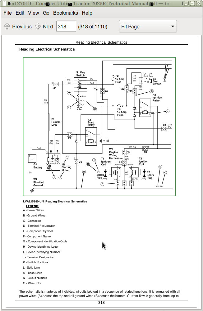
* Troubleshooting and electrical service procedures are combined with detailed wiring diagrams for ease of use.
* Notes, cautions and warnings throughout each chapter pinpoint critical information.
* Bold figure number help you quickly match illustrations with instructions.
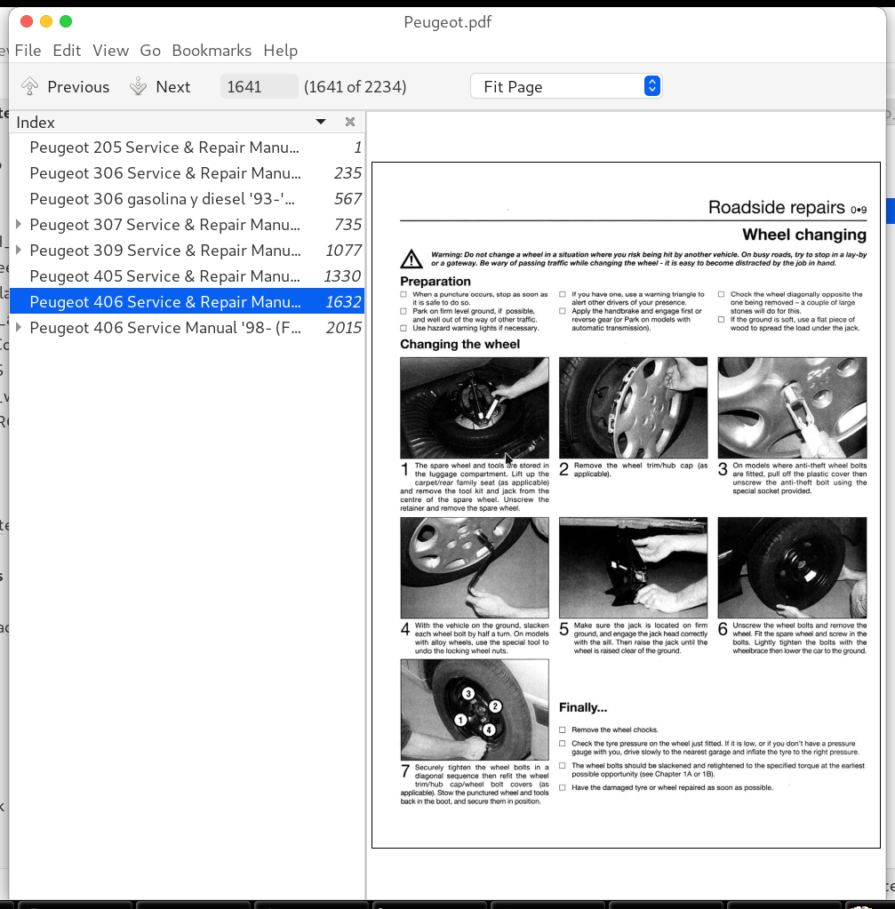
* Detailed illustrations, drawings and photos guide you through every procedure.
* Enlarged inset helps you identify and examine parts in detail.
Peugeot 406 Service Manual ’98- (FR)
Peugeot 205 Service & Repair Manual ’83-’97.pdf
Peugeot 206 Service & Repair Manual ’98-’09
Peugeot 306 gasolina y diesel ’93-’95 Service & Repair Manual (ES).pdf
Peugeot 306 Service & Repair Manual (EN) ’93-’95.pdf
Peugeot 307 Service & Repair Manual ’01-’04.pdf
Peugeot 309 Service & Repair Manual ’85-’97.pdf
Peugeot 405 Service & Repair Manual ’88-’97.pdf
Peugeot 406 Service & Repair Manual ’99-’02.pdf
PRODUCT DETAILS:
Total Pages: 2,234 pages
File Format: PDF
Language: English / French
TABLE OF CONTENTS
Peugeot 205 Service & Repair Manual ’83-’97…………….1
Peugeot 306 Service & Repair Manual (EN) ’93-’95…………….235
Peugeot 306 gasolina y diesel ’93-’95 Service & Repair Manual (ES)…………….567
Peugeot 307 Service & Repair Manual ’01-’04…………….735
Peugeot 309 Service & Repair Manual ’85-’97…………….1077
00. Living with your peugeot 309…………….1078
01. Engine…………….1093
02. Cooling system…………….1133
03. Fuel and exhause systems…………….1139
04. Ignition system…………….1153
05. Clutch…………….1161
06. Transmission…………….1165
07. Driveshafts…………….1171
08. Braking system…………….1173
09. Suspension hubs wheels and tyres…………….1187
10. Steering…………….1197
11. Bodywork and fitting…………….1201
12. Electrical system…………….1215
13. Supplement…………….1233
14. Wiring diagrams…………….1295
15. Ref…………….1309
Peugeot 405 Service & Repair Manual ’88-’97…………….1330
Peugeot 406 Service & Repair Manual ’99-’02…………….1632
Peugeot 406 Service Manual ’98- (FR)…………….2015
01…………….2015
PRÉSENTATION…………….2016
LIGNE -ÉQUIPEMENT…………….2017
02…………….2018
CARACTÉRISTIQUES…………….2018
Caractéristiques dimensionnelles et pondérales…………….2018
CARROSSERIE…………….2018
DIMENSIONS (mm)…………….2018
POIDS ET CHARGES (kg)…………….2018
Caractéristiques pratiques…………….2019
CAPACITÉS (l)…………….2019
PERFORMANCES (à titre indicatif pour la berline)…………….2019
CONSOMMATIONS (l)…………….2019
Identifications intérieures…………….2020
TEINTES PEINTURE…………….2020
03a…………….2022
CARACTÉRISTIQUES…………….2022
GÉNÉRALITÉS…………….2022
IDENTIFICATION DES MOTEURS…………….2022
SPÉCIFICATIONS GÉNÉRALES…………….2022
BLOC-CYLINDRES…………….2022
CHEMISES (sauf XU10)…………….2022
PISTONS…………….2023
AXES DE PISTONS…………….2024
SEGMENTS…………….2024
BIELLES…………….2024
VILEBREQUIN…………….2024
JEU PALIER DE VILEBREQUIN…………….2024
CHOIX DES COUSSINETS…………….2025
CULASSE…………….2026
SOUPAPES…………….2026
SIÈGES DE SOUPAPES (mm)…………….2026
GUIDES DE SOUPAPES (mm)…………….2027
DISTRIBUTION…………….2027
LUBRIFICATION…………….2027
CAPACITÉS (l)…………….2027
PRESSION D’HUILE…………….2027
REFROIDISSEMENT…………….2028
VASE D’EXPANSION…………….2028
THERMOSTAT…………….2028
MOTOVENTILATEUR ET THERMOCONTACT…………….2028
ALLUMAGE – INJECTION…………….2028
CARACTÉRISTIQUES DES SYSTÈMES D’INJECTION…………….2028
BOUGIES…………….2028
BOBINES…………….2028
CONTRÔLES…………….2028
CULASSE…………….2030
PLANS D’ENTRETIEN-RÉPARATION…………….2030
MÉTHODES DE RÉPARATION…………….2030
Dépose-repose du groupe motopropulseur…………….2030
Moteur 8 soupapes…………….2030
DÉPOSE…………….2030
REPOSE…………….2031
Moteur 16 soupapes……………..2031
DÉPOSE…………….2031
REPOSE…………….2032
Mise au point moteur…………….2032
Jeu aux poussoirs…………….2032
CONTRÔLE…………….2032
Distribution…………….2033
Moteur 8 soupape…………….2033
DÉPOSE DE LA COURROIE…………….2033
REPOSE DE LA COURROIE…………….2034
CONTRÔLE DU CALAGE ET CONTRÔLE DU CALAGE ET COURROIE…………….2034
Moteur 16 soupapes…………….2034
DÉPOSE DE LA COURROIE…………….2034
REPOSE DE LA COURROIE…………….2034
CONTRÔLE DE LA TENSION…………….2035
Lubrification…………….2037
Refroidissement…………….2037
REMPLISSAGE ET PURGE…………….2037
Allumage – injection…………….2038
Moteurs XU5 et XU7JB injection Magneti Marelli…………….2038
CONTRÔLE DE LA PRESSION D’ALIMENTATION…………….2038
CONTRÔLE CHUTE DE PRESSION…………….2038
CONTRÔLE DU DÉBIT…………….2039
CONTRÔLE RALENTI…………….2039
CONTRÔLE ANTIPOLLUTION…………….2039
CONTRÔLE ET RÉGLAGE AVANCE ALLUMAGE…………….2039
Moteur XU10J2TE injection Bosch MP3.2…………….2040
CONTRÔLE DE LA PRESSION D’ALIMENTATION…………….2040
CONTRÔLE CHUTE DE PRESSION…………….2040
CONTRÔLE DU DÉBIT…………….2040
CONTRÔLE RALENTI…………….2040
CONTRÔLE ANTIPOLLUTION…………….2040
CONTRÔLE ET RÉGLAGE AVANCE ALLUMAGE…………….2040
Moteurs XU7JP4 et XU10J4R injection Bosch MP5.1.1…………….2040
CONTRÔLE DE LA PRESSION D’ALIMENTATION…………….2040
CONTRÔLE DU DÉBIT…………….2040
CONTRÔLE RALENTI…………….2040
CONTRÔLE ANTIPOLLUTION…………….2040
CONTRÔLE AVANCE ALLUMAGE…………….2040
Révision de la culasse…………….2040
Moteurs XU5, XU7JB et XU10J2TE (simple arbre à cames)…………….2040
Dépose…………….2040
Démontage…………….2041
Contrôle…………….2041
Remontage…………….2041
Repose…………….2041
Moteurs XU7JP4 et XU10J4R (double arbres à cames)…………….2042
Dépose…………….2042
Démontage…………….2042
Contrôles…………….2043
Remontage…………….2043
Repose…………….2043
03b…………….2045
CARACTÉRISTIQUES…………….2045
GÉNÉRALITÉS…………….2045
IDENTIFICATION…………….2045
ATTELAGE MOBILE…………….2045
SPÉCIFICATIONS GÉNÉRALES…………….2045
Éléments constitutifs du moteur…………….2045
CARTER CYLINDRES…………….2045
VILEBREQUIN…………….2045
DEMI-COUSSINETS DE VILEBREQUIN…………….2045
BIELLE / PISTONS…………….2046
CARTERS DE CHAPEAUX DE PALIERS D’ARBRES À CAMES…………….2046
CULASSE…………….2046
ARBRES À CAMES…………….2046
JOINT DE CULASSE…………….2046
DISTRIBUTION…………….2046
LUBRIFICATION…………….2047
REFROIDISSEMENT…………….2047
ALLUMAGE – INJECTION…………….2047
MÉTHODES DE RÉPARATION…………….2049
Dépose – repose du groupe motopropulseur…………….2049
DÉPOSE…………….2049
REPOSE…………….2050
Mise au point moteur…………….2050
Jeu aux soupapes…………….2050
Distribution…………….2050
DÉPOSE DE LA COURROIE…………….2050
REPOSE DE LA COURROIE…………….2051
Lubrification…………….2052
Refroidissement…………….2052
VIDANGE…………….2052
REMPLISSAGE – PURGE…………….2053
Allumage – injection…………….2053
APPRENTISSAGE DU RALENTI MOTEUR…………….2053
AUTO-ADAPTIVITÉ DE LA RICHESSE…………….2053
ANALYSE DES DÉFAUTS…………….2053
Révision de la culasse…………….2054
Dépose de la culasse…………….2054
CONTRÔLE DE LA PLANÉITÉ…………….2054
CONTRÔLE DES VIS DE CULASSE…………….2055
DÉPOSE DES ARBRES À CAMES…………….2055
REPOSE DES ARBRES À CAMES…………….2055
IDENTIFICATION DES ARBRES À CAMES…………….2055
Repose de la culasse…………….2055
Interventions sur le moteur ne nécessitant pas sa dépose…………….2056
Dépose-repose joints à lèvres…………….2056
ÉCHANGE DU JOINT À LÈVRES D’ARBRE À CAMES…………….2056
ÉCHANGE DU JOINT À LÈVRES VILEBREQUIN (CÔTÉ DISTRIBUTION)…………….2057
ÉCHANGE DU JOINT À LÈVRES VILEBREQUIN (CÔTÉ VOLANT MOTEUR)…………….2057
Dépose-repose pompe à huile…………….2057
DÉPOSE…………….2057
REPOSE…………….2058
03c…………….2059
CARACTÉRISTIQUES…………….2059
GÉNÉRALITÉS…………….2059
SPÉCIFICATIONS GÉNÉRALES…………….2059
BLOC-CYLINDRES…………….2059
PISTONS…………….2060
VILEBREQUIN…………….2060
BIELLES…………….2060
CULASSE…………….2061
SOUPAPES…………….2061
SIÈGES DE SOUPAPES…………….2062
GUIDES DE SOUPAPES…………….2062
CHAMBRES DE TURBULENCE…………….2062
DISTRIBUTION…………….2063
ARBRE A CAMES…………….2063
JEUX AUX POUSSOIRS…………….2063
LUBRIFICATION…………….2063
POMPE A HUILE…………….2063
REFROIDISSEMENT…………….2063
THERMOSTAT…………….2063
MOTOVENTILATEUR…………….2063
THERMOCONTACT…………….2064
INJECTION…………….2064
POMPE D’INJECTION…………….2064
INJECTEURS…………….2064
SURALIMENTATION…………….2065
MÉTHODES DE RÉPARATION…………….2065
Dépose – repose du groupe motopropulseur…………….2065
DÉPOSE…………….2065
REPOSE…………….2066
Mise au point du moteur…………….2066
Jeu aux soupapes…………….2066
CONTRÔLE…………….2066
RÉGLAGE…………….2066
Distribution…………….2067
Moteur XUD9…………….2067
DÉPOSE DE LA COURROIE CRANTÉE…………….2067
REPOSE DE LA COURROIE CRANTÉE…………….2067
CONTRÔLE DU CALAGE DE LA DISTRIBUTION…………….2067
Moteur XUD11…………….2068
DÉPOSE DE LA COURROIE CRANTÉE…………….2068
REPOSE DE LA COURROIE CRANTÉE…………….2068
CONTRÔLE DU CALAGE DE LA DISTRIBUTION…………….2068
Lubrification…………….2069
CONTRÔLE DE LA PRESSION D’HUILE…………….2069
Refroidissement…………….2069
VIDANGE…………….2069
REMPLISSAGE ET PURGE…………….2069
Alimentation…………….2070
REMPLACEMENT FILTRE À GAZOLE…………….2070
Injection…………….2070
Moteur XUD9 (équipement Bosch)…………….2070
DÉPOSE POMPE D’INJECTION…………….2070
REPOSE POMPE D’INJECTION…………….2070
CALAGE DE LA POMPE D’INJECTION…………….2071
RÉGLAGES POMPE D’INJECTION…………….2071
Moteur XUD11 (équipement Lucas type Epic)…………….2073
DÉPOSE POMPE INJECTION…………….2073
REPOSE POMPE INJECTION…………….2073
CALAGE DE LA POMPE D’INJECTION…………….2073
RÉGLAGES POMPE D’INJECTION…………….2074
Injecteurs…………….2074
DÉPOSE…………….2074
REPOSE…………….2074
CONTRÔLE DES INJECTEURS…………….2074
Révision de la culasse…………….2075
Dépose…………….2075
Démontage…………….2075
Contrôle…………….2076
CONTRÔLE DU PLAN DE JOINT…………….2076
SOUPAPES…………….2076
PRÉCHAMBRES…………….2076
Remontage…………….2076
Repose…………….2077
04…………….2079
CARACTÉRISTIQUES…………….2079
MÉTHODES DE RÉPARATION…………….2079
Dépose-repose embrayage…………….2079
Pour BV BE 3/5…………….2079
DÉPOSE…………….2079
REPOSE…………….2079
Pour BV ML 5T…………….2079
DÉPOSE…………….2079
REPOSE…………….2079
Contrôles commande de débrayage à câble avec rattrapage automatique…………….2080
Déblocage commande de débrayage à câble avec rattrapage automatique (embrayage poussé)…………….2080
Déblocage commande de débrayage à câble avec rattrapage (embrayage tiré)…………….2080
Contrôle course de la pédale d’embrayage (BV ML 5T)…………….2080
Dépose-repose commande hydraulique d’embrayage…………….2081
DÉPOSE…………….2081
REPOSE D’UNE COMMANDE NEUVE…………….2081
05a…………….2082
CARACTÉRISTIQUES…………….2082
LUBRIFICATION…………….2082
IDENTIFICATION BOÎTES DE VITESSES…………….2082
RAPPORTS DE TRANSMISSION…………….2083
MÉTHODES DE RÉPARATION…………….2083
Dépose-repose boîte de vitesses (embrayage tiré) (B.V. BE3/5)…………….2083
DÉPOSE…………….2083
REPOSE…………….2084
Dépose-repose boîte de vitesses (embrayage poussé) (B.V. BE3/5)…………….2084
DÉPOSE…………….2084
REPOSE…………….2085
Dépose-repose boîte de vitesses (B.V.ML5T)…………….2085
DÉPOSE…………….2085
REPOSE…………….2086
Dépose-repose commande de vitesses à câbles (B.V. ML5T)…………….2086
DÉPOSE…………….2086
REPOSE…………….2087
05b…………….2088
CARACTÉRISTIQUES…………….2088
SPÉCIFICATIONS GÉNÉRALES…………….2088
RAPPORTS DE TRANSMISSION…………….2088
ÉVOLUTION…………….2088
MÉTHODES DE RÉPARATION…………….2089
CONTRÔLE NIVEAU D’HUILE…………….2089
VIDANGE EN CAS D’INTERVENTION…………….2089
REMPLISSAGE…………….2089
06…………….2090
CARACTÉRISTIQUES…………….2090
TABLEAUX D’AFFECTATION DES TRANSMISSIONS…………….2090
MÉTHODES DE RÉPARATION…………….2090
Dépose-repose transmission…………….2090
DÉPOSE…………….2090
REPOSE…………….2090
07a…………….2091
CARACTÉRISTIQUES…………….2091
SPÉCIFICATIONS GÉNÉRALES…………….2091
BARRE ANTIDÉVERS…………….2091
AFFECTATION DES RESSORTS…………….2091
MÉTHODES DE RÉPARATION…………….2092
Suspension AV…………….2092
Élément de suspension…………….2092
DÉPOSE…………….2092
REPOSE…………….2092
Amortisseur…………….2093
DÉPOSE…………….2093
REPOSE…………….2093
Palier de barre antidévers…………….2093
DÉPOSE…………….2093
IDENTIFICATION DES PALIERS…………….2093
REPOSE…………….2094
Train AV Triangle AV…………….2094
DÉPOSE…………….2094
REPOSE…………….2094
Articulations élastiques de triangle…………….2094
DÉPOSE…………….2094
REPOSE…………….2094
Pivot…………….2094
DÉPOSE…………….2094
REPOSE…………….2095
Roulement de roue AV…………….2095
DÉPOSE…………….2095
REPOSE…………….2095
Berceau…………….2096
DÉPOSE…………….2096
REPOSE…………….2096
Articulation élastique berceau AV…………….2096
DÉPOSE…………….2096
REPOSE…………….2097
07b…………….2098
CARACTÉRISTIQUES…………….2098
SPÉCIFICATIONS GÉNÉRALES…………….2098
BARRE ANTIDÉVERS…………….2098
AFFECTATION DES RESSORTS…………….2098
MÉTHODES DE RÉPARATION…………….2099
Suspension AR…………….2099
Amortisseur AR…………….2099
DÉPOSE…………….2099
REPOSE…………….2099
Paliers de barre antidévers…………….2099
DÉPOSE – REPOSE…………….2099
Train AR…………….2099
Train AR complet…………….2099
DÉPOSE…………….2099
REPOSE…………….2100
Articulation élastique de la traverse AR…………….2100
DÉPOSE…………….2100
REPOSE…………….2100
Bras longitudinal AR…………….2101
DÉPOSE…………….2101
REPOSE…………….2101
Articulation élastique du bras longitudinal AR…………….2101
DÉPOSE…………….2101
REPOSE…………….2101
Articulation élastique de palier AV du bras longitudinal…………….2101
DÉPOSE…………….2101
REPOSE…………….2101
Bras inférieur…………….2102
DÉPOSE…………….2102
REPOSE…………….2102
Pivot AR…………….2102
DÉPOSE…………….2102
REPOSE…………….2102
Articulation de pivot AR…………….2103
DÉPOSE…………….2103
REPOSE…………….2103
Moyeu-roulement AR…………….2103
DÉPOSE…………….2103
REPOSE…………….2103
08…………….2104
CARACTÉRISTIQUES…………….2104
Train AV…………….2104
PARALLÉLISME…………….2104
CHASSE…………….2104
CARROSSAGE…………….2104
PIVOT…………….2104
Train AR…………….2104
HAUTEUR DE CAISSE…………….2104
CARROSSAGE…………….2104
PARALLÉLISME…………….2104
MÉTHODES DE RÉPARATION…………….2104
Train AV…………….2104
PRÉCONISATION…………….2104
MISE EN ASSIETTE DE RÉFÉRENCE…………….2104
Contrôle et réglage…………….2105
CARROSSAGE…………….2105
CHASSE…………….2105
PIVOT…………….2105
PARALLÉLISME…………….2105
Train AR…………….2105
Hauteur de caisse…………….2105
Contrôle et réglage…………….2105
CARROSSAGE…………….2105
PARALLÉLISME…………….2105
09…………….2106
CARACTÉRISTIQUES…………….2106
SPÉCIFICATIONS GÉNÉRALES…………….2106
CIRCUIT D’ASSISTANCE…………….2106
MÉTHODES DE RÉPARATION…………….2107
Colonne de direction…………….2107
DÉPOSE…………….2107
REPOSE…………….2108
Crémaillère de direction…………….2108
DÉPOSE…………….2108
REPOSE…………….2109
Réglage du poussoir de crémaillère…………….2109
CRÉMAILLÈRE À VÉRIN SÉPARÉ…………….2109
CRÉMAILLÈRE À VÉRIN INTÉGRÉ…………….2109
Circuit hydraulique…………….2110
CONTRÔLE PRESSIONS D’ASSISTANCE…………….2110
VIDANGE…………….2111
REMPLISSAGE…………….2111
PURGE…………….2111
NIVEAU…………….2111
Particularités Airbag…………….2111
PRÉCAUTIONS GÉNÉRALES…………….2111
CONSIGNES DE SÉCURITÉ…………….2112
Dépose…………….2112
Repose…………….2112
MISE HORS SERVICE…………….2112
MISE EN SERVICE…………….2112
DÉPOSE-REPOSE SYSTÈME SAC GONFLABLE CONDUCTEUR…………….2112
Dépose…………….2112
Repose…………….2113
Réglage du contacteur à l’état libre…………….2113
10…………….2114
CARACTÉRISTIQUES…………….2114
SPÉCIFICATIONS GÉNÉRALES…………….2114
Freins AV…………….2114
Disque…………….2114
Étrier…………….2114
Plaquettes…………….2114
Freins AR…………….2114
Tambour…………….2114
Cylindre de roue…………….2114
Garnitures…………….2114
Disque…………….2114
Étrier…………….2114
Plaquettes…………….2114
Frein de parking…………….2114
Servofrein…………….2114
Maître-cylindre…………….2114
Compensateur de freinage…………….2114
Système ABR…………….2115
MÉTHODES DE RÉPARATION…………….2115
Freins AV…………….2115
Plaquettes…………….2115
Tous types sauf coupé 3,0 l……………..2115
DÉPOSE…………….2115
REPOSE…………….2115
Coupé 3,0 l……………..2115
DÉPOSE…………….2115
REPOSE…………….2116
Étrier de frein…………….2116
Tous types, sauf coupé 3,0 l…………….2116
DÉPOSE…………….2116
REPOSE…………….2116
Coupé 3,0 l……………..2116
DÉPOSE…………….2116
REPOSE…………….2116
Freins AR…………….2116
Plaquettes de frein…………….2116
DÉPOSE…………….2116
REPOSE…………….2117
Étrier de frein…………….2117
DÉPOSE…………….2117
REPOSE…………….2117
Segments de freins…………….2117
DÉPOSE…………….2117
REPOSE…………….2117
Commande des freins…………….2118
Garnitures de frein à main (version avec disques AR)…………….2118
DÉPOSE…………….2118
REPOSE…………….2118
Frein à main…………….2118
RÉGLAGE…………….2118
Amplificateur de freinage…………….2119
DÉPOSE…………….2119
REPOSE…………….2119
Maître-cylindre…………….2119
DÉPOSE…………….2119
REPOSE…………….2119
Compensateur asservi de freinage…………….2119
DÉPOSE…………….2119
REPOSE…………….2120
CONTRÔLE ET RÉGLAGE……………..2120
Circuit de freinage…………….2120
Vidange du réservoir…………….2120
Remplissage du circuit…………….2120
Purge automatique…………….2120
Purge manuelle (à la pédale)…………….2120
Système ABR…………….2121
Précautions à prendre…………….2121
Capteur de roue AV…………….2121
DÉPOSE…………….2121
REPOSE…………….2121
Diagnostic du système…………….2121
Capteur de roue AR…………….2122
DÉPOSE…………….2122
REPOSE…………….2122
Ensemble groupe de régulation calculateur…………….2122
DÉPOSE…………….2122
REPOSE…………….2122
Purge liquide de frein…………….2123
PRÉCAUTIONS À PRENDRE…………….2123
PURGE…………….2123
Schématique antiblocage de roues…………….2123
NOMENCLATURE…………….2123
FAISCEAUX…………….2123
CODIFICATIONS DES COULEURS…………….2123
12…………….2126
CARACTÉRISTIQUES…………….2126
Identifications intérieures…………….2126
TEINTES PEINTURE…………….2126
COMPOSITION DE LA CARROSSERIE…………….2127
REMPLACEMENT DES ÉLÉMENTS AMOVIBLES…………….2130
Dépose-repose bandeau de pare-chocs AV…………….2130
DÉPOSE…………….2130
REPOSE…………….2130
Dépose-repose pare- chocs AV…………….2130
DÉPOSE…………….2130
REPOSE…………….2130
Dépose-repose aile AV…………….2130
DÉPOSE…………….2130
REPOSE…………….2130
PARTICULARITÉS POUR COUPÉ…………….2130
Capot aluminium…………….2131
Dépose-repose porte AV…………….2131
DÉPOSE…………….2131
REPOSE…………….2131
Dépose-repose porte AR…………….2131
DÉPOSE…………….2131
REPOSE…………….2132
Dépose-repose bandeau de pare-chocs AR…………….2132
DÉPOSE…………….2132
REPOSE…………….2132
Dépose-repose pare-chocs AR…………….2132
DÉPOSE…………….2132
REPOSE…………….2132
PARTICULARITÉS POUR COUPÉ…………….2132
SELLERIE…………….2138
Informations sur le vitrage des 406…………….2138
VITRAGES POUR COUPÉ…………….2138
VITRAGES POUR BREAK…………….2138
Dépose-repose pare-brise…………….2138
DÉPOSE…………….2138
REPOSE…………….2139
Dépose-repose lunette AR…………….2139
DÉPOSE…………….2139
REPOSE…………….2139
Dépose-repose vitre de porte AR…………….2140
DÉPOSE…………….2140
REPOSE…………….2140
Dépose-repose vitre fixe de porte AR…………….2140
DÉPOSE…………….2140
REPOSE…………….2140
Dépose-repose vitre de porte AV…………….2140
DÉPOSE…………….2140
REPOSE…………….2140
Porte…………….2140
Dépose-repose panneau garniture de porte…………….2140
DÉPOSE…………….2140
REPOSE…………….2140
Dépose-repose mécanisme ouverture porte…………….2140
DÉPOSE…………….2140
REPOSE…………….2141
Dépose-repose verrou de porte AV…………….2141
DÉPOSE…………….2141
REPOSE…………….2141
Dépose-repose mécanisme lève-vitre…………….2141
DÉPOSE…………….2141
REPOSE…………….2141
Dépose-repose garniture de pavillon (Berline)…………….2141
DÉPOSE…………….2141
REPOSE…………….2142
Toit ouvrant…………….2142
Dépose-repose panneau mobile toit ouvrant…………….2142
DÉPOSE…………….2142
REPOSE…………….2142
Réglage…………….2142
Échange ensemble motoréducteur…………….2142
DÉPOSE…………….2142
REPOSE…………….2142
Dépose-repose toit ouvrant assemblé…………….2142
DÉPOSE…………….2142
REPOSE…………….2143
Planche de bord /console…………….2143
Dépose-repose visière de combiné…………….2143
DÉPOSE…………….2143
REPOSE…………….2143
Dépose-repose combiné…………….2143
DÉPOSE…………….2143
REPOSE…………….2143
Dépose-repose console de plancher…………….2143
DÉPOSE…………….2143
REPOSE…………….2144
Échange éléments boîtier antivol…………….2144
OUTILLAGE À RÉALISER…………….2144
DÉPOSE…………….2144
REPOSE…………….2144
Dépose-repose planche de bord…………….2144
DÉPOSE…………….2144
REPOSE…………….2145
Chauffage-Climatisation…………….2145
Dépose-repose boîtier commandes climatisation…………….2145
DÉPOSE…………….2145
REPOSE…………….2146
Dépose-repose aérotherme…………….2146
DÉPOSE…………….2146
REPOSE…………….2146
Dépose-repose climatiseur…………….2146
DÉPOSE…………….2146
REPOSE…………….2146
COLLECTION DE FIXATIONS…………….2148
REMPLACEMENT DES ÉLÉMENTS SOUDÉS…………….2151
Protections et sécurité…………….2151
PRÉCAUTIONS À PRENDRE SYSTÈME CENTRALISÉ SAC(S) GONFLABLE(S) ET SAC(S) GONFLABLE(S) ET…………….2151
MISE HORS SERVICE, SYSTÈME CENTRALISÉ SAC(S) GONFLABLE(S) ET CEINTURES…………….2151
MISE EN SERVICE, SYSTÈME CENTRALISÉ SAC(S) GONFLABLE(S) ET CEINTURES…………….2151
CONSIGNES DE SÉCURITÉ SAC GONFLABLE…………….2151
Précautions à prendre sur véhicules…………….2151
Dépose…………….2151
Repose…………….2151
Précautions à prendre avec les coussins……………..2151
Précautions à prendre pendant la manipulation des coussins…………….2151
Précautions générales…………….2151
CONSIGNES DE SÉCURITÉ CEINTURES PYROTECHNIQUES…………….2152
Précautions à prendre sur véhicules…………….2152
Dépose…………….2152
Repose…………….2152
Précautions à prendre sur le préten-sionneur/enrouleur…………….2152
Précautions générales…………….2152
PROCÉDURE D’INTERVENTION VÉHICULE ACCIDENTÉ…………….2152
Identification symboles utilisés dans les méthodes carrosserie…………….2152
Identification symboles des matériels de soudage par résistance…………….2153
Remplacement brancard AV coupe AV,semelle de brancard AV partielle, passage de roue AV partie AV, demi-façade AV et traverse …………….2153
Remplacement brancard AV complet,semelle de brancard AV et passage de roue AV partie AR assemblée…………….2154
Remplacement demi-façade avant (uniquement Coupé)…………….2155
Remplacement côté d’habitacle partie AV assemblé (sauf Coupé)…………….2156
Remplacement pied central (sauf Coupé)…………….2157
Remplacement bas de caisse (sauf Coupé)…………….2158
Remplacement pied avant assemblé (uniquement Coupé)…………….2158
Remplacement bas de caisse (uniquement Coupé)…………….2160
Remplacement pavillon (uniquement Coupé)…………….2160
Remplacement pavillon (Break)…………….2161
Remplacement pavillon (Berline)…………….2161
Remplacement aile AR assemblée (Berline)…………….2162
Remplacement passage de roue AR assemblé (Berline)…………….2163
Remplacement aile arrière partielle (uniquement Coupé)…………….2163
Remplacement passage de roue arrière assemblé (uniquement Coupé)…………….2164
Remplacement aile arrière partielle (Break)…………….2165
Remplacement passage de roue arrière assemblé (Break)…………….2166
Remplacement panneau AR assemblé (Berline)…………….2168
Remplacement appui feu AR (Berline)…………….2168
Remplacement plancher AR…………….2168
Remplacement longeron AR partiel…………….2169
Remplacement du panneau AR assemblé (uniquement Coupé)…………….2170
Remplacement appui feu AR (uniquement Coupé)…………….2170
Remplacement panneau AR – Doublure panneau AR (Break)…………….2171
CAISSE AU MARBRE…………….2172
CAR-O-LINER…………….2172
CELETTE…………….2178
DATALINER…………….2182
BLACKHAWK…………….2186
CAR CONTROL…………….2190
IDENTIFICATIONS…………….2192
13…………….2194
CONSEILS PRATIQUES…………….2194
POSTE DE CONDUITE…………….2195
Témoin de frein de stationnement et niveau mini de liquide de freins…………….2195
Témoin d’alerte centralisé (stop)…………….2195
Témoin de charge de la batterie…………….2195
Témoin d’antiblocage des roues (ABR)…………….2195
Témoin de pression d’huile moteur…………….2195
Témoin de niveau mini de liquide de refroidissement…………….2195
Préchauffage moteur Diesel…………….2195
Témoin de présence d’eau dans le filtre à gazole (suivant pays)…………….2195
Témoin d’autodiagnostic moteur…………….2195
Indicateur de température de liquide de refroidissement…………….2195
Témoin de niveau de carburant…………….2195
Témoin d’usure des plaquettes de frein AV…………….2196
Avertisseur sonore…………….2196
Avertisseur optique…………….2196
Indicateur de changement de position…………….2196
Commande d’éclairage…………….2196
Essuie-vitre AR…………….2196
Essuie-vitre automatique…………….2196
Désembuage lunette AR…………….2196
CHAUFFAGE…………….2197
Circuit de distribution d’air dans l’habitacle…………….2197
Dégivrage ou désembuage rapide du pare-brise et des vitres latérales…………….2197
L’obtention du confort passe par le réglage de quatre éléments essentiels…………….2197
Moteurs 1,6 l et 1,8 l injecction…………….2197
ENTRETIEN…………….2198
Moteur 1,8 l 16 V…………….2198
MOTEUR 2 L 16 V…………….2198
MOTEUR 2 L TURBO…………….2199
MOTEUR DIESEL TURBO 1,9 L 75 CV…………….2199
MOTEUR DIESEL TURBO 1,9 L…………….2199
MOTEUR DIESEL TURBO 2,1 L 12 V…………….2200
DÉPANNAGE…………….2200
Fusibles planche de bord…………….2200
Dépose-repose d’un fusible…………….2200
Changement des ampoules Rappel latéral de clignotant (W 5 W)…………….2201
15…………….2202
16…………….2204
17…………….2205
18…………….2206
AIDE…………….2207
Principaux raccourcis…………….2209
SOMMAIRE…………….2210
diesel…………….2211
MOTEURS TURBO DIESEL…………….2211
CARACTÉRISTIQUES GÉNÉRALES…………….2211
Caractéristiques dimensionnelles et pondérales…………….2211
CARROSSERIE…………….2211
DIMENSIONS (mm)…………….2211
POIDS ET CHARGES (kg)…………….2211
CARACTÉRISTIQUES PRATIQUES…………….2211
CAPACITÉS (l)…………….2211
PERFORMANCES (à titre indicatif pour la berline)…………….2211
CONSOMMATIONS (l)…………….2211
MOTEUR…………….2212
GÉNÉRALITÉS…………….2212
SPÉCIFICATIONS GÉNÉRALES…………….2212
ÉLÉMENTS CONSTITUTIFS DU MOTEUR…………….2212
BLOC-CYLINDRES…………….2212
IDENTIFICATION DU MOTEUR…………….2212
PISTONS…………….2213
VILEBREQUIN…………….2213
BIELLES…………….2213
CULASSE…………….2214
SOUPAPES…………….2214
SIÈGES DE SOUPAPES…………….2214
GUIDES DE SOUPAPES…………….2215
CHAMBRES DE TURBULENCE…………….2215
DISTRIBUTION…………….2216
ARBRE A CAMES…………….2216
JEUX AUX POUSSOIRS…………….2216
CALAGE DE LA DISTRIBUTION (XUD11)…………….2216
CALAGE DE DISTRIBUTION (XUD9)…………….2216
LUBRIFICATION…………….2217
POMPE A HUILE…………….2217
REFROIDISSEMENT…………….2217
THERMOSTAT…………….2217
MOTOVENTILATEUR…………….2217
THERMOCONTACT…………….2217
BOÎTE DE VITESSES MANUELLE…………….2217
LUBRIFICATION…………….2217
IDENTIFICATION BOÎTES DE VITESSES…………….2217
RAPPORTS DE TRANSMISSION…………….2217
GÉOMÉTRIE DES TRAINS…………….2218
Train AV…………….2218
HAUTEUR DE CAISSE…………….2218
PARALLÉLISME…………….2218
CHASSE…………….2218
CARROSSAGE…………….2218
PIVOT…………….2218
Train AR…………….2218
HAUTEUR DE CAISSE…………….2218
CARROSSAGE…………….2218
PARALLÉLISME…………….2218
COUPLES DES SERRAGE…………….2218
essence…………….2219
MOTEURS ESSENCE 4 Cylindes…………….2219
CARACTÉRISTIQUES GÉNÉRALES…………….2219
Caractéristiques dimensionnelles et pondérales…………….2219
CARROSSERIE…………….2219
DIMENSIONS (mm)…………….2219
POIDS ET CHARGES (kg)…………….2219
CARACTÉRISTIQUES PRATIQUES…………….2220
CAPACITÉS (l)…………….2220
PERFORMANCES (à titre indicatif pour la berline)…………….2220
CONSOMMATIONS (l)…………….2220
ROUES ET PNEUS…………….2220
MOTEUR…………….2220
GÉNÉRALITÉS…………….2220
IDENTIFICATION DES MOTEURS…………….2220
SPÉCIFICATIONS GÉNÉRALES…………….2221
ÉLÉMENTS CONSTITUTIFS DU MOTEUR…………….2221
BLOC-CYLINDRES…………….2221
CHEMISES (sauf XU10)…………….2221
PISTONS…………….2221
AXES DE PISTONS…………….2222
SEGMENTS…………….2222
BIELLES…………….2222
VILEBREQUIN…………….2222
JEU PALIER DE VILEBREQUIN…………….2223
CHOIX DES COUSSINETS…………….2223
CULASSE…………….2224
SOUPAPES…………….2224
SIÈGES DE SOUPAPES (mm)…………….2224
GUIDES DE SOUPAPES (mm)…………….2224
DISTRIBUTION…………….2225
ARBRE À CAMES…………….2225
JEU AUX POUSSOIRS…………….2225
CALAGE DE LA DISTRIBUTION (moteur 8 soupapes)…………….2225
CALAGE DE LA DISTRIBUTION (moteur 16 soupapes)…………….2225
COUPLES DE SERRAGE…………….2225
BOÎTE DE VITESSES MANUELLE…………….2225
LUBRIFICATION…………….2225
IDENTIFICATION BOÎTES DE VITESSES…………….2226
RAPPORTS DE TRANSMISSION…………….2226
GÉOMÉTRIE DES TRAINS…………….2226
Train AV…………….2226
HAUTEUR DE CAISSE…………….2226
PARALLÉLISME…………….2226
CHASSE…………….2226
CARROSSAGE…………….2226
PIVOT…………….2226
Train AR…………….2226
HAUTEUR DE CAISSE…………….2226
CARROSSAGE…………….2226
PARALLÉLISME…………….2226
essencev6…………….2227
MOTEUR V6…………….2227
CARACTÉRISTIQUES GÉNÉRALES…………….2227
Caractéristiques dimensionnelles et pondérales…………….2227
CARROSSERIE…………….2227
DIMENSIONS (mm)…………….2227
POIDS ET CHARGES (kg)…………….2227
CARACTÉRISTIQUES PRATIQUES…………….2227
CAPACITÉS (l)…………….2227
PERFORMANCES (à titre indicatif pour la berline)…………….2227
CONSOMMATIONS (l)…………….2227
ROUES ET PNEUS…………….2228
MOTEUR…………….2228
IDENTIFICATION…………….2228
SPÉCIFICATIONS GÉNÉRALES…………….2228
ÉLÉMENTS CONSTITUTIFS DU MOTEUR…………….2228
CARTER CYLINDRES…………….2228
VILEBREQUIN…………….2228
DEMI-COUSSINETS DE VILEBREQUIN…………….2229
BIELLE / PISTONS…………….2229
CARTERS DE CHAPEAUX DE PALIERS D’ARBRES À CAMES…………….2229
CULASSE…………….2229
ARBRES À CAMES…………….2229
JOINT DE CULASSE…………….2229
DISTRIBUTION…………….2229
PIGNON D’ARBRE À CAMES…………….2229
LUBRIFICATION…………….2229
REFROIDISSEMENT…………….2230
CARACTÉRISTIQUES…………….2230
ALLUMAGE – INJECTION…………….2230
CARACTÉRISTIQUES…………….2230
EMBRAYAGE…………….2230
BOÎTE DE VITESSES MÉCANIQUE…………….2230
LUBRIFICATION…………….2230
IDENTIFICATION BOÎTES DE VITESSES…………….2230
RAPPORTS DE TRANSMISSION…………….2230
BOÎTE DE VITESSES AUTOMATIQUE…………….2231
RAPPORTS DE TRANSMISSION…………….2231
ÉVOLUTION…………….2231
TRANSMISSION…………….2231
TABLEAUX D’AFFECTATION DES TRANSMISSIONS…………….2231
SUSPENSION – TRAIN AVANT…………….2231
SPÉCIFICATIONS GÉNÉRALES…………….2231
BARRE ANTIDÉVERS…………….2231
AFFECTATION DES RESSORTS…………….2231
SUSPENSION – TRAIN ARRIÈRE…………….2231
BARRE ANTIDÉVERS…………….2231
AFFECTATION DES RESSORTS…………….2231
GÉOMÉTRIE DES TRAINS…………….2231
Train AV…………….2231
HAUTEUR DE CAISSE…………….2231
PARALLÉLISME…………….2231
CHASSE…………….2231
CARROSSAGE…………….2232
PIVOT…………….2232
Train AR…………….2232
HAUTEUR DE CAISSE…………….2232
CARROSSAGE…………….2232
PARALLÉLISME…………….2232
DIRECTION…………….2232
CIRCUIT D’ASSISTANCE…………….2232
FREINS…………….2232
SPÉCIFICATIONS GÉNÉRALES…………….2232
Freins AV…………….2232
Disque…………….2232
Étrier…………….2232
Plaquettes…………….2232
Freins AR…………….2232
Tambour…………….2232
Cylindre de roue…………….2232
Garnitures…………….2232
Disque…………….2232
Étrier…………….2232
Plaquettes…………….2232
Frein de parking…………….2232
Commandes des freins…………….2233
Servofrein…………….2233
Maître-cylindre…………….2233
Compensateur de freinage…………….2233
Système ABR…………….2233
ÉQUIPEMENT ÉLECTRIQUE…………….2233
BATTERIE…………….2233
ALTERNATEUR…………….2233
COUPLES DE SERRAGE…………….2233
graissage…………….2234
Peugeot Models 205, 206, 306, 307, 309, 405, 406 Repair Service Manual