Posted on

Caterpillar 314C Excavators Factory Service & Shop Manual


INSTANT DOWNLOAD


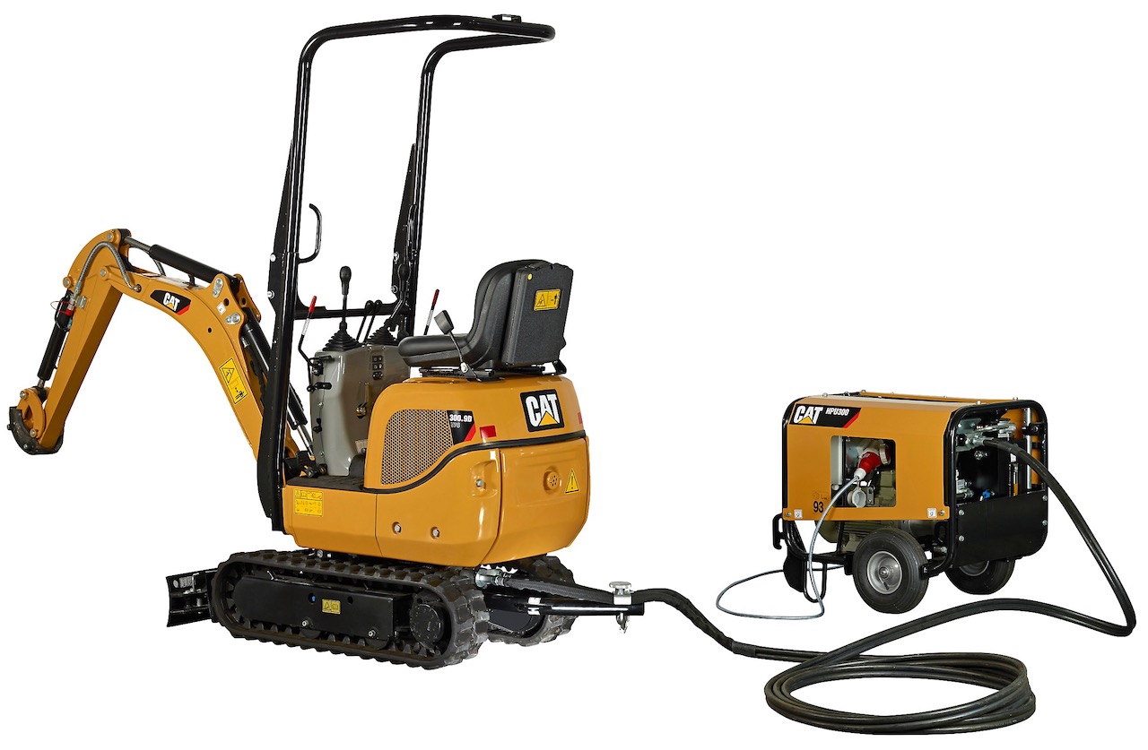
Complete workshop & service manual with electrical wiring diagrams for Caterpillar 314C Excavators. It’s the same service manual used by dealers that guaranteed to be fully functional and intact without any missing page.

This Caterpillar 314C Excavators service & repair manual (including maintenance, overhaul, disassembling & assembling, adjustment, tune-up, operation, inspecting, diagnostic & troubleshooting…) is divided into different sections. Each section covers a specific component or system with detailed illustrations. A table of contents is placed at the beginning of each section. Pages are easily found by category, and each page is expandable for great detail. The printer-ready PDF documents work like a charm on all kinds of devices.

EXCERPT:
├── KENR9522 – Schematic (311C U, 312C, 314C, 315C, 318C Excavator Electrical System – Attachment)
│   ├── Collage.pdf
│   └── Main.pdf
├── RENR5557 – Systems Operation (311C & 314C Excavators Electric and Electronic)
│   ├── Basic Operation.pdf
│   ├── Electrical System.pdf
│   ├── Engine Control System.pdf
│   ├── General Information.pdf
│   └── Monitoring System.pdf
├── RENR5557 – Testing & Adjusting (311C & 314C Excavators Electric and Electronic)
│   ├── Acceleration Cable and Deceleration Cable – Adjust.pdf
│   ├── Alarm Indicator for Engine Oil Pressure Is Illuminated and Action Alarm Is Activated – Troubleshoot.pdf
│   ├── Calibration Mode – Enter.pdf
│   ├── Charge Alarm Indicator Is Illuminated – Troubleshoot.pdf
│   ├── Charging System – Test.pdf
│   ├── Chassis Light Does Not Illuminate – Troubleshoot.pdf
│   ├── Circuit 303-BR – Troubleshoot.pdf
│   ├── Circuit 332-BU – Troubleshoot.pdf
│   ├── Controller Connector Contact Identification.pdf
│   ├── Controller – Replace.pdf
│   ├── Controller – Troubleshoot.pdf
│   ├── Dome Light Does Not Illuminate – Troubleshoot.pdf
│   ├── Electrical System Troubleshooting.pdf
│   ├── Engine Coolant Temperature Gauge Reads High or Gauge Quickly Moves Beyond Operating Range – Troubleshoot.pdf
│   ├── Engine Coolant Temperature Gauge Reads Low or Gauge Does Not Move – Troubleshoot.pdf
│   ├── Engine Speed Dial Does Not Work – Troubleshoot.pdf
│   ├── Engine Speed Does Not Respond to Engine Speed Dial – Troubleshoot.pdf
│   ├── Engine Stalls – Troubleshoot.pdf
│   ├── Fuel Gauge Reads High or Gauge Quickly Moves Beyond Operating Range – Troubleshoot.pdf
│   ├── Fuel Gauge Reads Low or Gauge Does Not Move – Troubleshoot.pdf
│   ├── General Information.pdf
│   ├── Governor Actuator – Calibrate.pdf
│   ├── Governor Actuator – Check.pdf
│   ├── Harness and Wire Identification.pdf
│   ├── High Speed Mode for Travel Does Not Activate – Troubleshoot.pdf
│   ├── Horn Does Not Sound – Troubleshoot.pdf
│   ├── Hydraulic Oil Temperature Gauge Reads High or Gauge Quickly Moves Beyond Operating Range – Troubleshoot.pdf
│   ├── Hydraulic Oil Temperature Gauge Reads Low or Gauge Does Not Move – Troubleshoot.pdf
│   ├── Implement Pressure Switch – Troubleshoot.pdf
│   ├── Indicator for Air Inlet Heater Does Not Illuminate – Troubleshoot.pdf
│   ├── Indicators Do Not Illuminate and Action Alarm Does Not Sound – Troubleshoot.pdf
│   ├── Indicators Do Not Illuminate – Troubleshoot.pdf
│   ├── Low Idle Indicator Does Not Respond to Low Idle Switch – Troubleshoot.pdf
│   ├── Low Idle System Does Not Respond to Low Idle Switch – Troubleshoot.pdf
│   ├── Monitor – Disassemble.pdf
│   ├── No Power – Troubleshoot.pdf
│   ├── Panel Light for Monitor Does Not Illuminate – Troubleshoot.pdf
│   ├── Power to Switch Panel – Troubleshoot.pdf
│   ├── Proportional Reducing Valve – Calibrate.pdf
│   ├── Radio Does Not Activate – Troubleshoot.pdf
│   ├── Radio Does Not Sound – Troubleshoot.pdf
│   ├── Service Hour Meter Does Not Activate – Troubleshoot.pdf
│   ├── Service Tools.pdf
│   ├── Speed Sensor – Replace.pdf
│   ├── Speed Sensor – Troubleshoot.pdf
│   ├── Starting Motor Does Not Rotate – Troubleshoot.pdf
│   ├── System Schematic.pdf
│   ├── Timer – Troubleshoot.pdf
│   ├── Travel Alarm Does Not Sound – Troubleshoot.pdf
│   ├── Travel Alarm Sounds while Travel Controls Are Released – Troubleshoot.pdf
│   ├── Travel Pressure Switch – Troubleshoot.pdf
│   ├── Window Washer Does Not Activate – Troubleshoot.pdf
│   ├── Wiper Motor Does Not Rotate – Troubleshoot.pdf
│   └── Wiper Motor Does Not Stop – Troubleshoot.pdf
├── RENR5599 – Specifications (308C CR, 314C CR and 321C CR Excavators Air Conditioning and Heating)
│   ├── Air Conditioner Lines.pdf
│   ├── Blower Motor.pdf
│   ├── Pressure Switch (Refrigerant Pressure Cutoff).pdf
│   ├── Refrigerant Compressor.pdf
│   ├── System Capacities for Refrigerant (Excavators) – 308C CR-321C CR.pdf
│   └── System Schematic.pdf
├── RENR5599 – Systems Operation (308C CR, 314C CR and 321C CR Excavators Air Conditioning and Heating)
│   ├── Actuator (Air Conditioner Control).pdf
│   ├── Air Conditioning and Heating System Sensor Operation.pdf
│   ├── Air Conditioning System.pdf
│   ├── Air Conditioning System Schematic.pdf
│   ├── Blower Motor.pdf
│   ├── Control Panel.pdf
│   ├── Evaporator Coil.pdf
│   ├── General Information.pdf
│   ├── Heater Core (Cab).pdf
│   ├── Heater System (Cab).pdf
│   ├── Heating System Schematic.pdf
│   ├── Motor (Air Conditioner Control).pdf
│   ├── Refrigerant Compressor.pdf
│   ├── Refrigerant Condenser.pdf
│   ├── Refrigerant Expansion Valve.pdf
│   ├── Refrigerant Receiver-Dryer.pdf
│   └── Speed Control – Power Transistor.pdf
├── RENR5599 – Testing & Adjusting (308C CR, 314C CR and 321C CR Excavators Air Conditioning and Heating)
│   ├── Actuator Troubleshooting – Abnormal Detection.pdf
│   ├── Air Conditioning System Schematic.pdf
│   ├── Air Conditioning System Troubleshooting – Guide for Actuators.pdf
│   ├── Air Conditioning System Troubleshooting – Guide for Sensors.pdf
│   ├── Belt – Test.pdf
│   ├── General Troubleshooting Information.pdf
│   ├── Heating System Schematic.pdf
│   ├── Manifold Gauge Set (Refrigerant) – Install.pdf
│   ├── Manifold Gauge Set (Refrigerant) – Remove.pdf
│   ├── Refrigerant Compressor Oil – Check.pdf
│   ├── Refrigerant Leakage – Test.pdf
│   ├── Refrigerant Recovery.pdf
│   ├── Refrigerant System – Charge.pdf
│   ├── Refrigerant System – Evacuate.pdf
│   ├── Refrigerant System – Flush.pdf
│   ├── Required Tools.pdf
│   ├── Sensor Troubleshooting.pdf
│   └── Visual Inspection.pdf
├── RENR6604 – Disassembly & Assembly (314C ExcavatorEngine Supplement)
│   ├── Air Cleaner – Remove and Install.pdf
│   ├── Air Conditioner Dryer – Remove and Install.pdf
│   ├── Air Inlet Heater – Remove and Install.pdf
│   ├── Alternator – Remove and Install.pdf
│   ├── Crankshaft Vibration Damper and Pulley – Remove and Install.pdf
│   ├── Cylinder Head – Install.pdf
│   ├── Cylinder Head – Remove.pdf
│   ├── Electric Starting Motor – Remove and Install.pdf
│   ├── Engine – Install.pdf
│   ├── Engine Oil Filter and Oil Filter Base – Remove and Install.pdf
│   ├── Engine Oil Level Gauge (Dipstick) – Remove and Install.pdf
│   ├── Expansion Tank – Remove and Install.pdf
│   ├── Fan Guard – Remove and Install.pdf
│   ├── Flywheel and Ring Gear – Remove and Install.pdf
│   ├── Fuel Filter (Primary) and Fuel Filter Base – Remove and Install.pdf
│   ├── Fuel Priming Pump – Remove and Install.pdf
│   ├── Governor Control Motor – Remove and Install.pdf
│   ├── Hood – Remove and Install.pdf
│   ├── Hydraulic Oil Cooler – Remove.pdf
│   ├── Muffler – Remove and Install.pdf
│   ├── Oil Pan – Remove and Install.pdf
│   ├── Radiator – Install.pdf
│   ├── Refrigerant Compressor – Remove and Install.pdf
│   ├── Refrigerant Condenser – Remove and Install.pdf
│   ├── System Pressure – Release.pdf
│   ├── Turbocharger – Install.pdf
│   ├── Turbocharger – Remove.pdf
│   ├── V-Belts – Remove and Install.pdf
│   ├── Water Pump – Install.pdf
│   ├── Water Pump – Remove.pdf
│   └── Water Separator – Remove and Install.pdf
├── RENR6605 – Specifications (314C CR Excavator Machine System Specifications)
│   ├── Accumulator (Pilot).pdf
│   ├── Blade Cylinder Lines.pdf
│   ├── Blade Lift Cylinder.pdf
│   ├── Blade Mounting.pdf
│   ├── Boom – 4650 mm (15 feet 3 inch).pdf
│   ├── Boom Cylinder Lines – Left Hand.pdf
│   ├── Boom Cylinder Lines – Right Hand.pdf
│   ├── Boom Cylinder.pdf
│   ├── Boom Lines – Auxiliary.pdf
│   ├── Boom Lines – Coupler.pdf
│   ├── Boom Lines.pdf
│   ├── Boom.pdf
│   ├── Bucket Adjuster.pdf
│   ├── Bucket Cylinder Lines.pdf
│   ├── Bucket Cylinder.pdf
│   ├── Bucket Linkage.pdf
│   ├── Bucket Sidecutter.pdf
│   ├── Cab Mounting.pdf
│   ├── Check Valve (Return Lines).pdf
│   ├── Control Valve (Blade).pdf
│   ├── Counterweight Mounting.pdf
│   ├── Final Drives and Travel Motors.pdf
│   ├── Front Idler.pdf
│   ├── Front Lines.pdf
│   ├── Fuel Tank.pdf
│   ├── Hydraulic Tank and Filter.pdf
│   ├── Joystick Control.pdf
│   ├── Main Hydraulic Pump Mounting.pdf
│   ├── Main Hydraulic Pump .pdf
│   ├── Main Hydraulic Pump.pdf
│   ├── Oil Filter (Hydraulic) – Case Drain.pdf
│   ├── Pilot Lines – Front.pdf
│   ├── Pilot Lines – Rear.pdf
│   ├── Pilot Valve (Joystick).pdf
│   ├── Pilot Valve (Oil Manifold).pdf
│   ├── Pilot Valve (Travel).pdf
│   ├── Pressure Reducing Valve (Boom Priority).pdf
│   ├── Pressure Reducing Valve (Boom Shock).pdf
│   ├── Pump Head (Main).pdf
│   ├── Pump Lines (Main).pdf
│   ├── Recoil Spring.pdf
│   ├── Return and Oil Filter Lines.pdf
│   ├── Stick – 2500 mm (8 feet 2 inch).pdf
│   ├── Stick – 3000 mm (9 feet 10 inch).pdf
│   ├── Stick Cylinder Lines.pdf
│   ├── Stick Cylinder.pdf
│   ├── Stick Lines – Auxiliary Hydraulic 2500 mm (8 feet 2 inch).pdf
│   ├── Stick Lines – Auxiliary Hydraulic 3000 mm (9 feet 10 inch).pdf
│   ├── Stick Lines.pdf
│   ├── Swing Drive.pdf
│   ├── Swing Gear and Bearing.pdf
│   ├── Swing Motor Lines.pdf
│   ├── Swing Motor.pdf
│   ├── Swivel.pdf
│   ├── Track Carrier Roller.pdf
│   ├── Track.pdf
│   ├── Track Roller Mounting.pdf
│   ├── Track Roller (Single Flange).pdf
│   ├── Travel Motor Guard.pdf
│   ├── Travel Motor Lines.pdf
│   └── Upper Frame.pdf
├── RENR6606 – Systems Operation (314C CR Excavator Hydraulic System)
│   ├── Accumulator (Pilot).pdf
│   ├── Blade Hydraulic System.pdf
│   ├── Boom Cylinder Decompression System.pdf
│   ├── Boom Hydraulic System.pdf
│   ├── Bucket Hydraulic System.pdf
│   ├── Check Valve (Load).pdf
│   ├── Combined Function Hydraulic System.pdf
│   ├── Control Valve (Boom Lowering).pdf
│   ├── Control Valve (Stick Lowering).pdf
│   ├── Control Valve (Straight Travel).pdf
│   ├── Cylinders (Boom, Stick and Bucket).pdf
│   ├── Displacement Change Valve.pdf
│   ├── Final Drive.pdf
│   ├── Gear Pump (Pilot).pdf
│   ├── General Information.pdf
│   ├── Hydraulic Filter (Pilot).pdf
│   ├── Hydraulic Tank and Filter.pdf
│   ├── Main Control Valve.pdf
│   ├── Main Hydraulic Pump.pdf
│   ├── Main Hydraulic System.pdf
│   ├── Negative Flow Control System.pdf
│   ├── Oil Makeup (Travel System).pdf
│   ├── One-Way Flow Hydraulic System.pdf
│   ├── Pilot Hydraulic System.pdf
│   ├── Pilot Valve (Joystick).pdf
│   ├── Pilot Valve (Travel and Steering).pdf
│   ├── Pump Control (Main Hydraulic).pdf
│   ├── Relief Valve (Line and Makeup).pdf
│   ├── Relief Valve (Main).pdf
│   ├── Relief Valve (Pilot).pdf
│   ├── Return Hydraulic System.pdf
│   ├── Solenoid Valve (Hydraulic Activation).pdf
│   ├── Solenoid Valve (Proportional Reducing).pdf
│   ├── Stick Hydraulic System.pdf
│   ├── Swing Drive.pdf
│   ├── Swing Hydraulic System.pdf
│   ├── Swing Motor.pdf
│   ├── Swing Parking Brake.pdf
│   ├── Swivel.pdf
│   ├── Travel Counterbalance Valve.pdf
│   ├── Travel Hydraulic System.pdf
│   ├── Travel Motor.pdf
│   ├── Travel Parking Brake.pdf
│   ├── Two Pump Hydraulic System.pdf
│   └── Two-Way Flow Hydraulic System.pdf
├── RENR6607 – Testing & Adjusting (314C CR Excavator Hydraulic System)
│   ├── Accumulator (Pilot) – Test and Charge.pdf
│   ├── Cylinder Drift – Check – Blade (If Equipped).pdf
│   ├── Cylinder Drift – Check – Empty Bucket.pdf
│   ├── Cylinder Drift – Check – Loaded Bucket.pdf
│   ├── Cylinder Speed – Check – Blade (If Equipped).pdf
│   ├── Cylinder Speed – Check – Boom, Stick and Bucket.pdf
│   ├── Engine Performance – Test – Engine Speed.pdf
│   ├── Flow Meter and Hose Setup – Basic.pdf
│   ├── Gear Pump (Blade) – Test.pdf
│   ├── Gear Pump (Pilot) – Test.pdf
│   ├── General Testing and Adjusting Information.pdf
│   ├── Hydraulic System Pressure – Release.pdf
│   ├── Hydraulic System – Setup.pdf
│   ├── Machine Drift on a Slope – Check.pdf
│   ├── Main Hydraulic Pump Air – Purge.pdf
│   ├── Main Pump (Flow) – Test.pdf
│   ├── One-Way Hydraulic System – Calibrate.pdf
│   ├── Operational Checks.pdf
│   ├── Overload Warning – Set – If Equipped.pdf
│   ├── Pump Control (Negative Flow) – Adjust.pdf
│   ├── Pump Control (Negative Flow) – Test.pdf
│   ├── Pump Control (Output Flow) – Adjust.pdf
│   ├── Relief Valve (Auxiliary) – Test and Adjust – Two-Way Work Tool.pdf
│   ├── Relief Valve (Blade) – Test and Adjust.pdf
│   ├── Relief Valve (Crossover) – Test and Adjust.pdf
│   ├── Relief Valve (Line) – Test and Adjust – Boom Lowering Control Valve.pdf
│   ├── Relief Valve (Line) – Test and Adjust.pdf
│   ├── Relief Valve (Line) – Test and Adjust – Stick Lowering Control Valve.pdf
│   ├── Relief Valve (Main) – Test and Adjust.pdf
│   ├── Relief Valve (Pilot) – Test and Adjust.pdf
│   ├── Relief Valve (Swing) – Test and Adjust.pdf
│   ├── Specifications.pdf
│   ├── Swing Motor – Test – Measurement of Case Drain Oil.pdf
│   ├── Swing Speed and Overswing on Level Ground – Check.pdf
│   ├── Swing Speed and Swing Drift on a Slope – Check.pdf
│   ├── Travel Motor – Test – Measurement of Case Drain Oil.pdf
│   ├── Travel on Level Ground – Test – Optional Test.pdf
│   ├── Travel on Level Ground – Test.pdf
│   └── Visual Inspection.pdf
├── RENR6609 – Schematic (313C & 314C Excavator Hydraulic System)
│   ├── Collage.pdf
│   └── Main.pdf
├── RENR6613 – Disassembly & Assembly (314C Excavator Excavator Systems)
│   ├── Accumulator – Remove and Install.pdf
│   ├── Actuator Motor (Damper Assembly) – Remove and Install.pdf
│   ├── Assembly Procedure for the Travel Motor.pdf
│   ├── Blade Cylinder – Remove and Install.pdf
│   ├── Blade – Remove and Install.pdf
│   ├── Boom Bearings and Seals – Install.pdf
│   ├── Boom Bearings and Seals – Remove.pdf
│   ├── Boom Cylinder – Remove and Install.pdf
│   ├── Boom Lighting – Remove and Install.pdf
│   ├── Bucket Cylinder – Remove and Install.pdf
│   ├── Bucket – Install.pdf
│   ├── Bucket Linkage Bearings and Seals – Install.pdf
│   ├── Bucket Linkage Bearings and Seals – Remove.pdf
│   ├── Bucket – Remove.pdf
│   ├── Cab – Install.pdf
│   ├── Cab – Remove.pdf
│   ├── Check Valve (Cooler Bypass) – Assemble.pdf
│   ├── Check Valve (Cooler Bypass) – Disassemble.pdf
│   ├── Check Valve (Cooler Bypass) – Install.pdf
│   ├── Check Valve (Cooler Bypass) – Remove.pdf
│   ├── Control Valve (Blade) – Disassemble.pdf
│   ├── Control Valve (Blade) – Install.pdf
│   ├── Control Valve (Blade) – Remove.pdf
│   ├── Counterweight – Remove and Install.pdf
│   ├── Disassembly Procedure.pdf
│   ├── Duo-Cone Conventional Seals – Install.pdf
│   ├── Evaporator Coil – Install.pdf
│   ├── Evaporator Coil – Remove.pdf
│   ├── Final Drive and Travel Motor – Install.pdf
│   ├── Final Drive and Travel Motor – Remove.pdf
│   ├── Final Drive Sprocket – Remove and Install.pdf
│   ├── Flow Control Valve (Boom Cylinder Decompression) – Assemble.pdf
│   ├── Flow Control Valve (Boom Cylinder Decompression) – Disassemble.pdf
│   ├── Flow Control Valve (Boom Cylinder Decompression) – Install.pdf
│   ├── Flow Control Valve (Boom Cylinder Decompression) – Remove.pdf
│   ├── Front Idler and Recoil Spring – Install.pdf
│   ├── Front Idler and Recoil Spring – Remove.pdf
│   ├── Fuel Tank – Install.pdf
│   ├── Fuel Tank – Remove.pdf
│   ├── Gear Pump (Blade) – Assemble.pdf
│   ├── Gear Pump (Blade) – Disassemble.pdf
│   ├── Gear Pump (Blade) – Install.pdf
│   ├── Gear Pump (Blade) – Remove.pdf
│   ├── Gear Pump (Pilot) – Assemble.pdf
│   ├── Gear Pump (Pilot) – Disassemble.pdf
│   ├── Gear Pump (Pilot) – Install.pdf
│   ├── Gear Pump (Pilot) – Remove.pdf
│   ├── Handle (Joystick) – Remove and Install.pdf
│   ├── Heater Core – Install.pdf
│   ├── Heater Core – Remove.pdf
│   ├── Heating and Air Conditioning Unit – Install.pdf
│   ├── Heating and Air Conditioning Unit – Remove.pdf
│   ├── Hydraulic Controls Activation Lever – Assemble.pdf
│   ├── Hydraulic Controls Activation Lever – Disassemble.pdf
│   ├── Hydraulic Controls Activation Lever – Install.pdf
│   ├── Hydraulic Controls Activation Lever – Remove.pdf
│   ├── Hydraulic Tank and Filter – Install.pdf
│   ├── Hydraulic Tank and Filter – Remove.pdf
│   ├── Installation Procedure .pdf
│   ├── Installation Procedure.pdf
│   ├── Main Control Valve – Assemble.pdf
│   ├── Main Control Valve – Disassemble.pdf
│   ├── Main Control Valve – Install.pdf
│   ├── Main Control Valve – Remove.pdf
│   ├── Main Hydraulic Pump – Install 01_03_2017.pdf
│   ├── Main Hydraulic Pump – Remove.pdf
│   ├── Operator Console – Remove and Install.pdf
│   ├── Pilot Valve (Blade) – Assemble.pdf
│   ├── Pilot Valve (Blade) – Disassemble.pdf
│   ├── Pilot Valve (Blade) – Install.pdf
│   ├── Pilot Valve (Blade) – Remove.pdf
│   ├── Pilot Valve (Implement) – Assemble.pdf
│   ├── Pilot Valve (Implement) – Disassemble.pdf
│   ├── Pilot Valve (Implement) – Install.pdf
│   ├── Pilot Valve (Joystick) – Assemble.pdf
│   ├── Pilot Valve (Joystick) – Disassemble.pdf
│   ├── Pilot Valve (Joystick) – Remove.pdf
│   ├── Pilot Valve (Oil Manifold) – Assemble.pdf
│   ├── Pilot Valve (Oil Manifold) – Install.pdf
│   ├── Pilot Valve (Oil Manifold) – Remove.pdf
│   ├── Pilot Valve (Travel) – Assemble.pdf
│   ├── Pilot Valve (Travel) – Disassemble.pdf
│   ├── Pilot Valve (Travel) – Install.pdf
│   ├── Pilot Valve (Travel) – Remove.pdf
│   ├── Pressure Switch (Refrigerant Pressure Cutoff) – Remove and Install.pdf
│   ├── Pump Control – Assemble.pdf
│   ├── Pump Control – Disassemble.pdf
│   ├── Pump Control – Install.pdf
│   ├── Pump Control – Remove.pdf
│   ├── Recoil Spring – Assemble.pdf
│   ├── Recoil Spring – Disassemble.pdf
│   ├── Seat – Remove and Install.pdf
│   ├── Seat Support – Remove and Install.pdf
│   ├── Speed Control – Remove and Install.pdf
│   ├── Stick Bearings and Seals – Install.pdf
│   ├── Stick Bearings and Seals – Remove.pdf
│   ├── Stick – Install.pdf
│   ├── Stick – Remove.pdf
│   ├── Swing Drive – Disassemble – Older Style.pdf
│   ├── Swing Drive – Install.pdf
│   ├── Swing Drive – Remove.pdf
│   ├── Swing Gear and Bearing – Remove and Install.pdf
│   ├── Swing Motor – Assemble.pdf
│   ├── Swing Motor – Disassemble.pdf
│   ├── Swing Motor – Install.pdf
│   ├── Swing Motor – Remove.pdf
│   ├── Swivel – Assemble.pdf
│   ├── Swivel – Disassemble.pdf
│   ├── Swivel – Remove.pdf
│   ├── System Pressure – Release.pdf
│   ├── Temperature Sensor (Ambient Air) – Remove and Install.pdf
│   ├── Track Adjuster – Assemble.pdf
│   ├── Track Adjuster – Disassemble.pdf
│   ├── Track Adjuster – Install.pdf
│   ├── Track Adjuster – Remove.pdf
│   ├── Track Carrier Roller – Install.pdf
│   ├── Track Carrier Roller – Remove.pdf
│   ├── Track – Connect.pdf
│   ├── Track Roller – Install.pdf
│   ├── Track – Separate.pdf
│   ├── Two Pump) – Remove and Install.pdf
│   ├── Undercarriage Frame – Install.pdf
│   └── Undercarriage Frame – Remove.pdf
├── RENR6615 – Schematic (314C Excavator Electrical System)
│   ├── Collage.pdf
│   └── Main.pdf
├── RENR6657 – Schematic (314C CR Excavator with Blade Hydraulic System (Attachment))
│   ├── Collage.pdf
│   └── Main.pdf
├── RENR9140 – Schematic (314C Excavator Hydraulic System (Attachment))
│   ├── Collage.pdf
│   └── Main.pdf
├── RENR9149 – Schematic (314C Excavator Hydraulic System (Attachment))
│   ├── Collage.pdf
│   └── Main.pdf
├── SENR6572 – Disassembly & Assembly (Disassembly & Assembly ZEXEL FUEL SYSTEM)
│   ├── Fuel Priming and Transfer Pump.pdf
│   ├── Fuel Pump Housing.pdf
│   └── Governor.pdf
├── SENR6572 – Systems Operations (Disassembly & Assembly ZEXEL FUEL SYSTEM).pdf
├── SENR6572 – Testing & Adjusting (Disassembly & Assembly ZEXEL FUEL SYSTEM).pdf
├── UENR3207 – Schematic (314C Excavator Electrical System)
│   ├── Collage.pdf
│   └── Main.pdf
├── UENR3208 – Schematic (314C Excavator Electrical System)
│   ├── Collage.pdf
│   └── Main.pdf
├── UENR3209 – Schematic (314C Excavator Electrical System)
│   ├── Collage.pdf
│   └── Main.pdf
└── UENR3210 – Schematic (314C Excavator Electrical System)
├── Collage.pdf
└── Main.pdf


INSTANT DOWNLOAD


Posted on

Caterpillar 303.5E2 CR, 304E2 CR, 304.5E2 XTC, 305E2 CR, 305.5E2, 305.5E2 CR Mini Hydraulic Excavators Factory Service & Shop Manual


INSTANT DOWNLOAD


Complete workshop & service manual with electrical wiring diagrams for Caterpillar 303.5E2 CR, 304E2 CR, 304.5E2 XTC, 305E2 CR, 305.5E2, 305.5E2 CR Mini Hydraulic Excavators. It’s the same service manual used by dealers that guaranteed to be fully functional and intact without any missing page.

This Caterpillar 303.5E2 CR, 304E2 CR, 304.5E2 XTC, 305E2 CR, 305.5E2, 305.5E2 CR Mini Hydraulic Excavators service & repair manual (including maintenance, overhaul, disassembling & assembling, adjustment, tune-up, operation, inspecting, diagnostic & troubleshooting…) is divided into different sections. Each section covers a specific component or system with detailed illustrations. A table of contents is placed at the beginning of each section. Pages are easily found by category, and each page is expandable for great detail. The printer-ready PDF documents work like a charm on all kinds of devices.

FILELIST:
├── M0069048 – Troubleshooting (304E2 CR, 305E2 CR, 305.5E2 CR Mini Hydraulic Excavator Machine ECM)
│   ├── CAN Data Link – Test.pdf
│   ├── Connector Contact Description.pdf
│   ├── Connector Locations.pdf
│   ├── Determining Diagnostic Trouble Codes.pdf
│   ├── Diagnostic Capabilities.pdf
│   ├── Diagnostic Trouble Codes.pdf
│   ├── ECM – Configure.pdf
│   ├── ECM – Replace.pdf
│   ├── ECM Software – Install.pdf
│   ├── Electrical Connector – Inspect.pdf
│   ├── Electrical Power Supply – Test.pdf
│   ├── Engine Speed Control – Test.pdf
│   ├── Event Codes.pdf
│   ├── General Information.pdf
│   ├── Operator Control Switch (Switch to Ground) – Test.pdf
│   ├── Sensor Signal (Analog, Passive) – Test.pdf
│   ├── Sensor Signal (PWM) – Test.pdf
│   ├── Sensor Supply – Test.pdf
│   ├── Service Tools.pdf
│   ├── Solenoid Valve – Test.pdf
│   ├── System Schematic.pdf
│   ├── Wiring Harness (Open Circuit) – Test.pdf
│   └── Wiring Harness (Short Circuit) – Test.pdf
├── UENR4294 – Systems Operation (303.5E2 CR, 304E2 CR, 304.5E2 XTC, 305E2 CR, 305.5E2 CR Mini Hydraulic Excavators Hydraulic System)
│   ├── Accumulator (Pilot).pdf
│   ├── Blade Hydraulic System.pdf
│   ├── Boom Hydraulic System.pdf
│   ├── Bucket Hydraulic System.pdf
│   ├── Bypass Valve (Return) – Bypass Check Valve.pdf
│   ├── Check Valve (Load).pdf
│   ├── Check Valve (Return Makeup) – Slow Return Check Valve.pdf
│   ├── Cylinders (Boom, Stick and Bucket).pdf
│   ├── Displacement Change Valve.pdf
│   ├── Final Drive.pdf
│   ├── General Information.pdf
│   ├── Hydraulic Oil Cooler.pdf
│   ├── Hydraulic Tank and Filter.pdf
│   ├── Main Control Valve.pdf
│   ├── Main Hydraulic Pump.pdf
│   ├── Main Hydraulic System (1).pdf
│   ├── Main Hydraulic System (2).pdf
│   ├── Oil Makeup (Swing System).pdf
│   ├── Oil Makeup (Travel System).pdf
│   ├── One-Way Flow Hydraulic System.pdf
│   ├── Pilot Hydraulic System.pdf
│   ├── Pilot Valve (Joystick).pdf
│   ├── Pilot Valve (Swing Parking Brake).pdf
│   ├── Pilot Valve (Travel).pdf
│   ├── Pump Control (Main Hydraulic).pdf
│   ├── Quick Coupler System – If Equipped.pdf
│   ├── Relief Valve (Line).pdf
│   ├── Relief Valve (Swing).pdf
│   ├── Return Hydraulic System.pdf
│   ├── Solenoid Valve (Hydraulic Lockout).pdf
│   ├── Stick Hydraulic System.pdf
│   ├── Swing Drive.pdf
│   ├── Swing Hydraulic System.pdf
│   ├── Swing Motor.pdf
│   ├── Swivel.pdf
│   ├── Travel Counterbalance Valve.pdf
│   ├── Travel Hydraulic System.pdf
│   ├── Travel Motor.pdf
│   ├── Travel Parking Brake.pdf
│   └── Two-Way Flow Hydraulic System.pdf
├── UENR4294 – Testing & Adjusting (303.5E2 CR, 304E2 CR, 304.5E2 XTC, 305E2 CR, 305.5E2 CR Mini Hydraulic Excavators Hydraulic System)
│   ├── Accumulator (Pilot) – Test and Charge.pdf
│   ├── Cutoff Pressure (Main Pump) – Test and Adjust.pdf
│   ├── Cylinder Drift – Check.pdf
│   ├── Cylinder Speed – Check.pdf
│   ├── Engine Performance – Test – Engine Speed.pdf
│   ├── General Testing and Adjusting Information.pdf
│   ├── Hydraulic System Air – Purge.pdf
│   ├── Hydraulic System Pressure – Release.pdf
│   ├── Machine Drift on a Slope – Check.pdf
│   ├── Main Hydraulic Pump Air – Purge.pdf
│   ├── Main Pump (Flow) – Test.pdf
│   ├── Main Pump Solenoid – Calibrate.pdf
│   ├── Margin Pressure – Test and Adjust.pdf
│   ├── Operational Checks.pdf
│   ├── Pump Control (Output Flow) – Adjust.pdf
│   ├── Relief Valve (Auxiliary) – Test and Adjust – If Equipped.pdf
│   ├── Relief Valve (Line) – Test and Adjust.pdf
│   ├── Relief Valve (Pilot) – Test and Adjust.pdf
│   ├── Relief Valve (Swing) – Test and Adjust.pdf
│   ├── Specifications.pdf
│   ├── Swing Motor – Test – Measurement of Case Drain Oil.pdf
│   ├── Swing Speed and Overswing on Level Ground – Check.pdf
│   ├── Swing Speed and Swing Drift on a Slope – Check.pdf
│   ├── Travel Motor – Test – Measurement of Case Drain Oil.pdf
│   ├── Travel on Level Ground – Test – Optional Test.pdf
│   ├── Travel on Level Ground – Test.pdf
│   └── Visual Inspection.pdf
├── UENR5188 – Schematic (303.5E2 CR, 304E2 CR, 304.5E2 XTC, 305E2 CR, 305.5E2 CR Mini Excavator Hydraulic System)
│   └── Main.pdf
├── UENR5591 – Disassembly & Assembly (303.5E2 CR, 304E2 CR, 305.5E2 CR, 305E2 CR Mini Hydraulic Excavators Engine Supplement)
│   ├── Alternator – Remove and Install (1).pdf
│   ├── Alternator – Remove and Install (2).pdf
│   ├── Battery – Remove and Install.pdf
│   ├── Electric Starting Motor – Remove and Install.pdf
│   ├── Engine and Main Hydraulic Pump – Remove and Install.pdf
│   ├── Fan – Remove and Install.pdf
│   ├── Fuel Filter and Water Separator Base – Remove and Install.pdf
│   ├── Fuel Shutoff Solenoid – Remove and Install.pdf
│   ├── Fuel Transfer and Priming Pump – Remove and Install.pdf
│   ├── Hood – Remove and Install.pdf
│   ├── Hydraulic Oil Cooler – Remove and Install.pdf
│   ├── Muffler – Remove and Install.pdf
│   ├── Oil Pan – Remove and Install.pdf
│   ├── Radiator – Remove and Install.pdf
│   ├── Refrigerant Compressor – Remove and Install.pdf
│   ├── Refrigerant Condenser – Remove and Install.pdf
│   ├── Refrigerant Receiver-Dryer – Remove and Install.pdf
│   ├── System Pressure – Release.pdf
│   ├── Water Pump – Remove and Install.pdf
│   └── Water Temperature Regulator – Remove and Install.pdf
├── UENR5592 – Disassembly & Assembly (303.5E2 CR, 304E2 CR, 305.5E2 CR, 305E2 CR Mini Hydraulic Excavators Machine Systems)
│   ├── Accumulator (Hydraulic Pilot) – Remove and Install.pdf
│   ├── Blade Cylinder – Remove and Install.pdf
│   ├── Blade – Remove and Install.pdf
│   ├── Blower Motor (Air Conditioner, Heater) – Remove and Install.pdf
│   ├── Boom Cylinder – Remove and Install.pdf
│   ├── Boom – Remove and Install.pdf
│   ├── Bucket Cylinder – Remove and Install.pdf
│   ├── Bucket Linkage – Remove and Install.pdf
│   ├── Bucket – Remove and Install.pdf
│   ├── Cab – Remove and Install.pdf
│   ├── Canopy – Remove and Install.pdf
│   ├── Counterweight – Remove and Install.pdf
│   ├── Duo-Cone Conventional Seals – Install.pdf
│   ├── Evaporator Coil – Remove and Install.pdf
│   ├── Final Drive and Travel Motor – Assemble.pdf
│   ├── Final Drive and Travel Motor – Disassemble.pdf
│   ├── Final Drive and Travel Motor – Remove and Install.pdf
│   ├── Front Idler, Recoil Spring and Hydraulic Track Adjuster – Remove and Install.pdf
│   ├── Front Idler – Remove and Install.pdf
│   ├── Fuel Tank – Remove and Install.pdf
│   ├── Heater Core – Remove and Install.pdf
│   ├── Heating and Air Conditioning Unit – Remove and Install.pdf
│   ├── Hydraulic Tank – Remove and Install.pdf
│   ├── Hydraulic Track Adjusters – Remove and Install.pdf
│   ├── Load Control Valve (Boom Cylinder) – Remove and Install.pdf
│   ├── Main Control Valve – Assemble.pdf
│   ├── Main Control Valve – Disassemble.pdf
│   ├── Main Control Valve – Remove and Install.pdf
│   ├── Main Hydraulic Pump – Assemble.pdf
│   ├── Main Hydraulic Pump – Disassemble.pdf
│   ├── Main Hydraulic Pump – Remove and Install.pdf
│   ├── Pilot Valve (Travel) – Assemble.pdf
│   ├── Pilot Valve (Travel) – Disassemble.pdf
│   ├── Pilot Valve (Travel) – Remove and Install.pdf
│   ├── Platform – Remove and Install.pdf
│   ├── Seat – Remove and Install.pdf
│   ├── Selector Valve (Alternate Pattern Control) – Remove and Install.pdf
│   ├── Sprocket – Remove and Install.pdf
│   ├── Stick Cylinder – Remove and Install.pdf
│   ├── Stick – Remove and Install.pdf
│   ├── Support (Swing Boom) – Remove and Install.pdf
│   ├── Swing Boom Cylinder – Remove and Install.pdf
│   ├── Swing Motor and Swing Drive – Assemble.pdf
│   ├── Swing Motor and Swing Drive – Disassemble.pdf
│   ├── Swing Motor and Swing Drive – Remove and Install.pdf
│   ├── Swivel – Assemble.pdf
│   ├── Swivel – Disassemble.pdf
│   ├── Swivel – Remove and Install.pdf
│   ├── System Pressure – Release.pdf
│   ├── Track Carrier Roller – Remove and Install.pdf
│   ├── Track – Connect.pdf
│   ├── Track – Remove and Install.pdf
│   ├── Track Roller – Remove and Install.pdf
│   ├── Track – Separate.pdf
│   ├── Upper Frame and Undercarriage Frame – Connect.pdf
│   └── Upper Frame and Undercarriage Frame – Separate.pdf
├── UENR5697 – Specifications (303.5E2 CR, 304.5E2 XTC, 304E2 CR, 305.5E2 CR, 305E2 CR Mini Hydraulic Excavators Machine System Specifications)
│   ├── Accumulator (Pilot).pdf
│   ├── Air Cleaner.pdf
│   ├── Air Conditioner Lines.pdf
│   ├── Air Conditioner.pdf
│   ├── Air Lines.pdf
│   ├── Auxiliary Hydraulic Lines.pdf
│   ├── Blade Cylinder – Angle.pdf
│   ├── Blade Cylinder.pdf
│   ├── Blade Lift Cylinder.pdf
│   ├── Blade Mounting.pdf
│   ├── Boom – 2.406 m (7.8937 ft).pdf
│   ├── Boom – 2.506 m (8.22179 ft).pdf
│   ├── Boom – 2.578 m (8.4580 ft).pdf
│   ├── Boom – 2.722 m (8.9305 ft).pdf
│   ├── Boom Cylinder.pdf
│   ├── Boom Lines.pdf
│   ├── Bucket Cylinder.pdf
│   ├── Bucket Lines.pdf
│   ├── Bucket Linkage.pdf
│   ├── Bucket Mounting.pdf
│   ├── Cab Air Duct.pdf
│   ├── Cab Heater and Mounting.pdf
│   ├── Cab Heater.pdf
│   ├── Cab.pdf
│   ├── Cab – Trim Group.pdf
│   ├── Control Valve – Swing Valve.pdf
│   ├── Counterweight.pdf
│   ├── Coupler Lines.pdf
│   ├── Cylinder Guard.pdf
│   ├── Disconnect Switch.pdf
│   ├── Electric Horn.pdf
│   ├── Engine Mounting.pdf
│   ├── Flood Lighting – Boom.pdf
│   ├── Flood Lighting – Cab.pdf
│   ├── Flood Lighting – Canopy.pdf
│   ├── Front Idler.pdf
│   ├── Front Lines.pdf
│   ├── Fuel Lines – Filter.pdf
│   ├── Fuel Tank and Mounting.pdf
│   ├── Governor Control.pdf
│   ├── Handrail.pdf
│   ├── Heater Lines.pdf
│   ├── Hoist Solenoid Valve.pdf
│   ├── Hydraulic Accumulator and Mounting.pdf
│   ├── Hydraulic Hand Control.pdf
│   ├── Hydraulic Tank and Filter.pdf
│   ├── Joystick Control.pdf
│   ├── Main Control Valve.pdf
│   ├── Main Hydraulic Pump Mounting.pdf
│   ├── Main Hydraulic Pump.pdf
│   ├── Manual Valve (Auxiliary).pdf
│   ├── Mounting Bracket – Tilt Group.pdf
│   ├── Oil Filter (Hydraulic).pdf
│   ├── Operator Console – Left Hand.pdf
│   ├── Operator Console – Right Hand.pdf
│   ├── Pilot Lines.pdf
│   ├── Pilot Operated Hydraulic Control.pdf
│   ├── Pilot Valve (Joystick).pdf
│   ├── Pilot Valve (Travel).pdf
│   ├── Pressure Sensor.pdf
│   ├── Pump Control Valve.pdf
│   ├── Pump Lines.pdf
│   ├── Quick Coupler.pdf
│   ├── Radiator and Hydraulic Oil Cooler.pdf
│   ├── Radio (AM357200242FM).pdf
│   ├── Rear Cover.pdf
│   ├── Rear View Mirror.pdf
│   ├── Recoil Spring.pdf
│   ├── Refrigerant Compressor Mounting.pdf
│   ├── Refrigerant Compressor.pdf
│   ├── Refrigerant Condenser and Mounting.pdf
│   ├── Relief Valve.pdf
│   ├── Return Lines.pdf
│   ├── Solenoid Valve (Quick Coupler).pdf
│   ├── Sound Suppression Cover.pdf
│   ├── Sprocket.pdf
│   ├── Stick – 1.266 m (4.1535 ft).pdf
│   ├── Stick – 1.321 m (4.3340 ft).pdf
│   ├── Stick – 1.424 m (4.6719 ft).pdf
│   ├── Stick – 1.566 m (5.1378 ft).pdf
│   ├── Stick – 1.621 m (5.3182 ft).pdf
│   ├── Stick – 1.7565 m (5.76280 ft).pdf
│   ├── Stick – 1.824 m (5.9843 ft).pdf
│   ├── Stick Cylinder.pdf
│   ├── Stick Lines.pdf
│   ├── Swing Boom Cylinder.pdf
│   ├── Swing Cylinder Lines.pdf
│   ├── Swing Drive Mounting.pdf
│   ├── Swing Frame.pdf
│   ├── Swing Gear and Bearing.pdf
│   ├── Swivel (1).pdf
│   ├── Swivel (2).pdf
│   ├── Track Carrier Roller.pdf
│   ├── Track.pdf
│   ├── Track Roller (Center Flange).pdf
│   ├── Track Roller Mounting.pdf
│   ├── Travel Motor and Mounting.pdf
│   ├── Travel Motor Lines – Angle Blade.pdf
│   ├── Travel Motor Lines.pdf
│   ├── Upper Frame.pdf
│   ├── Window Wiper Motor.pdf
│   ├── Window Wiper.pdf
│   ├── Wiring (Cab).pdf
│   └── Wiring (Console).pdf
├── UENR6663 – Schematic (304E2 CR, 305E2 CR, 305.5E2 CR Mini Excavator Electrical System)
│   ├── Collage.pdf
│   └── Main.pdf
├── UENR6974 – Schematic (304E2 CR, 305E2 CR, 305.5E2 CR Mini Hydraulic Excavator Electrical System)
│   ├── Collage.pdf
│   └── Main.pdf
├── UENR7460 – Schematic (304E2 CR, 305E2 CR, 305.5E2 CR Mini Excavator Electrical System)
│   └── Main.pdf
└── UENR7461 – Schematic (304E2 CR, 305E2 CR, 305.5E2 CR Mini Hydraulic Excavator Electrical System)
└── Main.pdf


INSTANT DOWNLOAD


Posted on

Caterpillar 300.9D Mini Hydraulic Factory Service & Shop Manual


Download Link

INSTANT DOWNLOAD (add to cart)

Complete workshop & service manual with electrical wiring diagrams for Caterpillar 300.9D Mini Hydraulic. It’s the same service manual used by dealers that guaranteed to be fully functional and intact without any missing page.

This service manual for Caterpillar 300.9D Mini Hydraulic is divided into different sections. Each section covers a specific component or system with detailed illustrations. A table of contents is placed at the beginning of each section. Pages are easily found by category, and each page is expandable for great detail. The printer-ready PDF documents work like a charm on all kinds of devices.

UENR5416 – Schematic (300.9D Mini Hydraulic Excavator Electrical System)
UENR0478 – Specifications (300.9D Mini Hydraulic Excavator)
UENR0478 – Systems Operation (300.9D Mini Hydraulic Excavator)
UENR0478 – Testing & Adjusting (300.9D Mini Hydraulic Excavator)
UENR1774 – Schematic (300.9D Mini Excavator Hydraulic System)
UENR2937 – Specifications (300.9D VPS Mini Hydraulic Excavator Machine Systems)
UENR3279 – Disassembly & Assembly (3TNV70 & 3TNV76 Engines for Caterpillar Built Machines)

EXCERPT:
Cooling System – Check
This engine has a pressurized cooling system. A pressurized cooling system has two advantages. The cooling system can be operated in a safe manner at a temperature higher than the normal boiling point (steam) of water.
This type of system prevents cavitation in the water pump. Cavitation is the forming of low-pressure bubbles in liquids that are caused by mechanical forces. The formation of an air pocket or a steam pocket in this type of cooling system is difficult.

Posted on

Caterpillar Loaders 277C, 277C2, 287C, 287C2, 297C Factory Service & Shop Manual


INSTANT DOWNLOAD


Complete workshop & service manual with electrical wiring diagrams for Caterpillar Loaders 277C, 277C2, 287C, 287C2, 297C. It’s the same service manual used by dealers that guaranteed to be fully functional and intact without any missing page.

This Caterpillar Loaders 277C, 277C2, 287C, 287C2, 297C service & repair manual (including maintenance, overhaul, disassembling & assembling, adjustment, tune-up, operation, inspecting, diagnostic & troubleshooting…) is divided into different sections. Each section covers a specific component or system with detailed illustrations. A table of contents is placed at the beginning of each section. Pages are easily found by category, and each page is expandable for great detail. The printer-ready PDF documents work like a charm on all kinds of devices.

FILELIST:
├── KENR5118 – Schematic (246C, 256C, 262C, 272C Skid Steer Loader & 277C, 287C, 297C Multi-Terrain Loader Electrical System)
│   ├── Collage.pdf
│   └── Main.pdf
├── KENR5191 – Disassembly & Assembly (279C2 Compact Track Loader & 287C, 277C, 277C2, 297C Multi Terrain Loaders Engine Supplement)
│   ├── Aftercooler Fan and Mounting – Remove and Install.pdf
│   ├── Aftercooler – Remove and Install.pdf
│   ├── Air Cleaner – Remove and Install.pdf
│   ├── Alternator – Remove and Install.pdf
│   ├── Battery and Battery Cable – Separate and Connect.pdf
│   ├── Cab – Tilt.pdf
│   ├── Electric Starting Motor – Remove and Install.pdf
│   ├── Engine Enclosure – Remove and Install.pdf
│   ├── Engine – Install .pdf
│   ├── Engine – Remove .pdf
│   ├── Fuel Priming Pump and Primary Filter (Water Separator) – Remove and Install.pdf
│   ├── Gear Motor (Fan, Aftercooler) – Assemble.pdf
│   ├── Gear Motor (Fan, Aftercooler) – Disassemble.pdf
│   ├── Gear Motor (Fan, Aftercooler) – Install.pdf
│   ├── Gear Motor (Fan, Aftercooler) – Remove.pdf
│   ├── Gear Motor (Fan) – Assemble.pdf
│   ├── Gear Motor (Fan) – Disassemble.pdf
│   ├── Gear Motor (Fan) – Install.pdf
│   ├── Gear Motor (Fan) – Remove.pdf
│   ├── Muffler – Remove and Install.pdf
│   ├── Pump Mounting – Remove and Install.pdf
│   ├── Radiator and Hydraulic Oil Cooler – Install.pdf
│   ├── Radiator and Hydraulic Oil Cooler – Remove.pdf
│   ├── System Pressure – Release.pdf
│   ├── Turbocharger – Remove and Install.pdf
│   ├── Water Pump – Remove and Install.pdf
│   └── Water Temperature Regulator – Remove and Install.pdf
├── KENR5195 – Specifications (277C, 277C2, 287C, 287C2, 297C Multi Terrain Loaders Machine Systems)
│   ├── Bogie Suspension.pdf
│   ├── Bogie Wheel.pdf
│   ├── Control Manifold and Solenoid (Work Tool Positioner).pdf
│   ├── Control Manifold (Motor, 2-Speed).pdf
│   ├── Control Manifold (Pilot Shutoff).pdf
│   ├── Control Manifold (Quick Coupler).pdf
│   ├── Control Valve (Work Tool).pdf
│   ├── Coupler Cylinder.pdf
│   ├── Electrohydraulic Control (Joystick) – Left.pdf
│   ├── Electrohydraulic Control (Joystick) – Right.pdf
│   ├── Engine Enclosure.pdf
│   ├── Fuel Tank and Mounting.pdf
│   ├── Gas Spring Group (Cab).pdf
│   ├── Gear Motor (Fan, Aftercooler).pdf
│   ├── Gear Motor (Fan, Demand).pdf
│   ├── Gear Pump.pdf
│   ├── Hydraulic Accumulator (Pilot Oil).pdf
│   ├── Hydraulic Oil Filter.pdf
│   ├── Hydrostatic Pump and Mounting.pdf
│   ├── Idler Wheel.pdf
│   ├── Lift Arm Cylinder and Mounting.pdf
│   ├── Lift Cylinder .pdf
│   ├── Lift Cylinder.pdf
│   ├── Machine Frame and Mounting.pdf
│   ├── Piston Motor (Hydrostatic) – 2 Speed Motor.pdf
│   ├── Piston Motor (Hydrostatic).pdf
│   ├── Piston Pump (Hydrostatic).pdf
│   ├── Piston Pump (Work Tool) – High Flow.pdf
│   ├── Quick Coupler.pdf
│   ├── Radiator and Hydraulic Oil Cooler (Fan).pdf
│   ├── Radiator and Oil Cooler Mounting.pdf
│   ├── Return Manifold.pdf
│   ├── ROPS Mounting.pdf
│   ├── Specifications .pdf
│   ├── Sprocket.pdf
│   ├── Tilt Cylinder – Left Hand.pdf
│   ├── Tilt Cylinder – Right Hand.pdf
│   ├── Track Drive.pdf
│   ├── Track Tensioner.pdf
│   ├── Undercarriage Axle and Mounting.pdf
│   └── Undercarriage.pdf
├── KENR5196 – Systems Operation (277C, 277C2, 287C, 287C2, 297C Multi Terrain Loaders Machine Systems)
│   ├── Control Manifold and Solenoid (Work Tool Positioner) – If Equipped.pdf
│   ├── Control Valve (Work Tool) – High Flow.pdf
│   ├── Control Valve (Work Tool) – Standard Flow.pdf
│   ├── Electrohydraulic System.pdf
│   ├── Gear Pump – Charge Oil.pdf
│   ├── General Information – High Flow.pdf
│   ├── General Information – Standard Flow.pdf
│   ├── Governor Control.pdf
│   ├── Hydrostatic System.pdf
│   ├── Piston Motor (Hydrostatic).pdf
│   ├── Piston Pump (Hydrostatic).pdf
│   ├── Piston Pump (Work Tool) – If Equipped.pdf
│   ├── Undercarriage.pdf
│   ├── Work Tool Hydraulic System – High Flow.pdf
│   └── Work Tool Hydraulic System – Standard Flow.pdf
├── KENR5196 – Testing & Adjusting (277C, 277C2, 287C, 287C2, 297C Multi Terrain Loaders Machine Systems)
│   ├── Accumulator (Pilot) – Test and Charge.pdf
│   ├── Gear Motor (Fan) – Test – ATAAC Fan (If Equipped).pdf
│   ├── Gear Motor (Fan) – Test.pdf
│   ├── High Flow Hydraulic System – Test and Adjust – If Equipped.pdf
│   ├── Hydraulic Oil Contamination – Test.pdf
│   ├── Hydraulic System Troubleshooting.pdf
│   ├── Hydrostatic System – Flush and Fill.pdf
│   ├── Hydrostatic System Troubleshooting.pdf
│   ├── Line Relief Valve – Test and Adjust.pdf
│   ├── Machine Preparation.pdf
│   ├── Main Relief Valve – Test and Adjust.pdf
│   ├── Operational Checks.pdf
│   ├── Pilot System Pressure – Test.pdf
│   ├── Pump Flow – Test.pdf
│   ├── System Pressure – Release.pdf
│   ├── Visual Inspection.pdf
│   └── Worksheets – Troubleshoot.pdf
├── KENR5197 – Disassembly & Assembly (279C2 Compact Track Loader & 287C, 277C, 277C2, 297C Multi Terrain Loaders Power Train)
│   ├── Axle (Front) – Remove and Install.pdf
│   ├── Axle (Rear) – Remove and Install.pdf
│   ├── Bogie Suspension – Assemble – Level 1.pdf
│   ├── Bogie Suspension – Assemble – Level 2.pdf
│   ├── Bogie Suspension – Disassemble – Level 1.pdf
│   ├── Bogie Suspension – Disassemble – Level 2.pdf
│   ├── Bogie Suspension – Install – Level 1.pdf
│   ├── Bogie Suspension – Install – Level 2.pdf
│   ├── Bogie Suspension – Remove – Level 1.pdf
│   ├── Bogie Suspension – Remove – Level 2.pdf
│   ├── Bogie Wheel – Remove and Install.pdf
│   ├── Idler Axle – Assemble.pdf
│   ├── Idler Axle – Disassemble.pdf
│   ├── Idler Axle – Install – Front.pdf
│   ├── Idler Axle – Install – Rear.pdf
│   ├── Idler Axle – Remove – Front.pdf
│   ├── Idler Axle – Remove – Rear.pdf
│   ├── Idler Wheel – Remove and Install.pdf
│   ├── Piston Motor (Hydrostatic) – Assemble – CTL.pdf
│   ├── Piston Motor (Hydrostatic) – Assemble – Final Drive Bench Method.pdf
│   ├── Piston Motor (Hydrostatic) – Assemble.pdf
│   ├── Piston Motor (Hydrostatic) – Disassemble – CTL.pdf
│   ├── Piston Motor (Hydrostatic) – Disassemble – Final Drive Bench Method.pdf
│   ├── Piston Motor (Hydrostatic) – Disassemble.pdf
│   ├── Piston Motor (Hydrostatic) – Install.pdf
│   ├── Piston Motor (Hydrostatic) – Remove.pdf
│   ├── Piston Pump (Hydrostatic) – Assemble.pdf
│   ├── Piston Pump (Hydrostatic) – Disassemble.pdf
│   ├── Piston Pump (Hydrostatic) – Install.pdf
│   ├── Piston Pump (Hydrostatic) – Remove.pdf
│   ├── Solenoid Valve (Motor, 2-Speed) – Remove and Install.pdf
│   ├── System Pressure – Release.pdf
│   ├── Track Drive – Assemble.pdf
│   ├── Track Drive – Disassemble.pdf
│   ├── Track Drive – Install.pdf
│   ├── Track Drive – Remove.pdf
│   ├── Track (Rubber) – Detension and Tension.pdf
│   ├── Track (Rubber) – Remove and Install.pdf
│   ├── Track Tensioner – Remove and Install.pdf
│   ├── Undercarriage – Assemble – Level 1.pdf
│   ├── Undercarriage – Assemble – Level 2.pdf
│   ├── Undercarriage – Disassemble – Level 1.pdf
│   ├── Undercarriage – Disassemble – Level 2.pdf
│   ├── Undercarriage – Install.pdf
│   └── Undercarriage – Remove.pdf
├── KENR5198 – Disassembly & Assembly (287C2 Compact Track Loader & 287C, 277C, 277C2, 297C Multi Terrain Loaders Machine Systems)
│   ├── Accumulator Manifold and Solenoid Mounting (Pilot Shutoff) – Remove and Install.pdf
│   ├── Air Conditioner and Heater – Assemble.pdf
│   ├── Air Conditioner and Heater – Disassemble.pdf
│   ├── Air Conditioner and Heater – Install.pdf
│   ├── Air Conditioner and Heater – Remove.pdf
│   ├── Cab – Install.pdf
│   ├── Cab – Remove.pdf
│   ├── Cab – Tilt.pdf
│   ├── Control Manifold and Solenoid (Work Tool Positioner) – Remove and Install.pdf
│   ├── Control Manifold (Quick Coupler) – Remove and Install.pdf
│   ├── Control Valve (Work Tool) – Assemble – High Flow.pdf
│   ├── Control Valve (Work Tool) – Assemble.pdf
│   ├── Control Valve (Work Tool) – Disassemble – High Flow.pdf
│   ├── Control Valve (Work Tool) – Disassemble.pdf
│   ├── Control Valve (Work Tool) – Install – High Flow.pdf
│   ├── Control Valve (Work Tool) – Install.pdf
│   ├── Control Valve (Work Tool) – Remove – High Flow.pdf
│   ├── Control Valve (Work Tool) – Remove.pdf
│   ├── Coupler Cylinder – Remove and Install.pdf
│   ├── Electrohydraulic Control (Joystick) – Install.pdf
│   ├── Electrohydraulic Control (Joystick) – Remove.pdf
│   ├── Fuel Tank – Remove and Install.pdf
│   ├── Gas Spring – Remove and Install – Extended Reach.pdf
│   ├── Gear Pump (Charge) – Assemble – High Flow.pdf
│   ├── Gear Pump (Charge) – Assemble.pdf
│   ├── Gear Pump (Charge) – Disassemble – High Flow.pdf
│   ├── Gear Pump (Charge) – Disassemble.pdf
│   ├── Gear Pump (Charge) – Install – High Flow.pdf
│   ├── Gear Pump (Charge) – Install.pdf
│   ├── Gear Pump (Charge) – Remove – High Flow.pdf
│   ├── Gear Pump (Charge) – Remove.pdf
│   ├── Hydraulic Accumulator (Pilot Oil) – Remove and Install.pdf
│   ├── Hydraulic Tank – Install.pdf
│   ├── Hydraulic Tank – Remove.pdf
│   ├── Lift Arms – Install – Radial Lift.pdf
│   ├── Lift Arms – Install – Vertical Lift.pdf
│   ├── Lift Arms – Remove – Radial Lift.pdf
│   ├── Lift Arms – Remove – Vertical Lift.pdf
│   ├── Lift Cylinder – Remove and Install.pdf
│   ├── Piston Pump – Assemble – High Flow.pdf
│   ├── Piston Pump – Disassemble – High Flow.pdf
│   ├── Piston Pump – Install.pdf
│   ├── Piston Pump – Remove.pdf
│   ├── Quick Coupler – Remove and Install – Hydraulic.pdf
│   ├── Refrigerant Accumulator – Remove and Install.pdf
│   ├── Refrigerant Compressor – Remove and Install.pdf
│   ├── Refrigerant Condenser – Remove and Install.pdf
│   ├── Seat – Remove and Install.pdf
│   ├── System Pressure – Release.pdf
│   ├── Tilt Cylinder – Remove and Install.pdf
│   └── Window Wiper Motor – Remove and Install.pdf
├── KENR5199 – Schematic (277C, 277C2, 287C, 287C2, 297C Multi-Terrain Loader Hydraulic System)
│   ├── Collage.pdf
│   └── Main.pdf
├── KENR5969 – Systems Operation (279C, 279C2, 289C, 289C2, 299C Compact Track Loaders & 287C, 277C, 277C2, 287C2, 297C Multi Terrain Loaders & 246C, 256C, 262C, 262C2, 272C Skid Steer Loaders Monitoring System)
│   ├── Data Link.pdf
│   ├── Display Module.pdf
│   ├── General Information .pdf
│   ├── Input Components.pdf
│   ├── Monitoring System.pdf
│   ├── Operator Mode.pdf
│   ├── Output Components.pdf
│   ├── Powerup Test.pdf
│   ├── Service Mode.pdf
│   ├── System Schematic.pdf
│   └── Warning Operation.pdf
├── KENR8666 – Schematic (246C, 256C, 262C, 272C Skid Steer Loader & 277C, 287C, 297C Multi-Terrain Loader & 279C, 289C, 299C Compact Track Loader Electrical System)
│   ├── Collage.pdf
│   └── Main.pdf
└── UENR1753 – Schematic (246C, 256C, 262C, 262C2, 272C Skid Steer Loaders & 277C, 277C2, 287C, 287C2, 297C Multi-Terrain Loader & 279C, 279C2, 289C, 289C2, 299C Compact Track Loader Electrical System)
├── Collage.pdf
└── Main.pdf


INSTANT DOWNLOAD


Posted on

Caterpillar 279C, 279C2, 289C, 289C2, 299C Compact Track Loaders Factory Service & Shop Manual


INSTANT DOWNLOAD


Complete workshop & service manual with electrical wiring diagrams for Caterpillar 279C, 279C2, 289C, 289C2, 299C Compact Track Loaders. It’s the same service manual used by dealers that guaranteed to be fully functional and intact without any missing page.

This Caterpillar 279C, 279C2, 289C, 289C2, 299C Compact Track Loaders service & repair manual (including maintenance, overhaul, disassembling & assembling, adjustment, tune-up, operation, inspecting, diagnostic & troubleshooting…) is divided into different sections. Each section covers a specific component or system with detailed illustrations. A table of contents is placed at the beginning of each section. Pages are easily found by category, and each page is expandable for great detail. The printer-ready PDF documents work like a charm on all kinds of devices.

FILELIST:
├── KENR5119 – Systems Operation (279C/242C2, 289C/242C2, 299C & 287C, 277C/242C2, 287C2, 297C & 246C, 256C, 262C/242C2, 272C Machine Electronic Control System)
│   ├── Data Link.pdf
│   ├── Electrical Input Components.pdf
│   ├── Electrical Output Components.pdf
│   ├── Electronic Control Module.pdf
│   ├── Features.pdf
│   ├── General Information.pdf
│   └── Location of Electrical Components.pdf
├── KENR5119 – Testing & Adjusting (279C/242C2, 289C/242C2, 299C & 287C, 277C/242C2, 287C2, 297C & 246C, 256C, 262C/242C2, 272C Machine Electronic Control System)
│   ├── Calibration.pdf
│   ├── Electrical Connector – Inspect.pdf
│   ├── Electronic Control Module (ECM) – Configure.pdf
│   ├── Electronic Control Module (ECM) – Flash Program.pdf
│   ├── Electronic Control Module (ECM) – Replace.pdf
│   ├── System Schematic.pdf
│   ├── Wiring Harness (Open Circuit) – Test.pdf
│   └── Wiring Harness (Short Circuit) – Test.pdf
├── KENR5119 – Troubleshooting (279C/242C2, 289C/242C2, 299C & 287C, 277C/242C2, 287C2, 297C & 246C, 256C, 262C/242C2, 272C Machine Electronic Control System)
│   ├── Connector Locations.pdf
│   ├── Diagnostic Capabilities.pdf
│   ├── Diagnostic Code List.pdf
│   ├── Emerging Symptom Information.pdf
│   ├── Event Code List.pdf
│   ├── General Information.pdf

│   ├── Motor Speed Is Unexpected.pdf
│   ├── Power Supply Circuit of Electronic Control Module.pdf
│   ├── Pulse Width Modulated Sensor.pdf
│   ├── Service Tools.pdf
│   ├── Starting System.pdf
│   ├── Switch Circuits.pdf
│   ├── Symptom Troubleshooting.pdf
│   ├── Using Caterpillar Electronic Technician to Determine Diagnostic Codes.pdf
│   └── Using the Operator Monitor to Determine Diagnostic Codes.pdf
├── KENR5969 – Systems Operation (279C/242C2, 289C/242C2, 299C & 287C, 277C/242C2, 287C2, 297C & 246C, 256C, 262C/242C2, 272C Machine Electronic Control System)
│   ├── Data Link.pdf
│   ├── Display Module.pdf
│   ├── General Information.pdf
│   ├── Input Components.pdf
│   ├── Monitoring System.pdf
│   ├── Operator Mode.pdf
│   ├── Output Components.pdf
│   ├── Powerup Test.pdf
│   ├── Service Mode.pdf
│   ├── System Schematic.pdf
│   └── Warning Operation.pdf
├── KENR8828 – Disassembly & Assembly (279C, 289C, 289C2, 299C Compact Track Loaders & 287C2 Multi Terrain Loader Engine Supplement)
│   ├── Aftercooler Fan and Mounting – Remove and Install.pdf
│   ├── Aftercooler – Remove and Install.pdf
│   ├── Air Cleaner – Remove and Install.pdf
│   ├── Alternator – Remove and Install.pdf
│   ├── Battery and Battery Cable – Separate and Connect.pdf
│   ├── Cab – Tilt.pdf
│   ├── Electric Starting Motor – Remove and Install.pdf
│   ├── Engine Enclosure – Remove and Install.pdf
│   ├── Engine – Install .pdf
│   ├── Engine – Install.pdf
│   ├── Engine – Remove .pdf
│   ├── Fuel Priming Pump and Primary Filter (Water Separator) – Remove and Install.pdf
│   ├── Gear Motor (Fan, Aftercooler) – Assemble.pdf
│   ├── Gear Motor (Fan, Aftercooler) – Disassemble.pdf
│   ├── Gear Motor (Fan, Aftercooler) – Install.pdf
│   ├── Gear Motor (Fan, Aftercooler) – Remove.pdf
│   ├── Gear Motor (Fan) – Assemble.pdf
│   ├── Gear Motor (Fan) – Disassemble.pdf
│   ├── Gear Motor (Fan) – Install.pdf
│   ├── Gear Motor (Fan) – Remove.pdf
│   ├── Muffler – Remove and Install.pdf
│   ├── Pump Mounting – Remove and Install.pdf
│   ├── Radiator and Hydraulic Oil Cooler – Install.pdf
│   ├── Radiator and Hydraulic Oil Cooler – Remove.pdf
│   ├── System Pressure – Release.pdf
│   ├── Turbocharger – Remove and Install.pdf
│   ├── Water Pump – Remove and Install.pdf
│   └── Water Temperature Regulator – Remove and Install.pdf
├── KENR8829 – Specifications (279C, 279C2, 289C, 289C2, 299C Compact Track Loaders Machine Systems)
│   ├── Control Manifold and Solenoid (Work Tool Positioner).pdf
│   ├── Control Manifold (Motor, 2-Speed).pdf
│   ├── Control Manifold (Pilot Shutoff).pdf
│   ├── Control Manifold (Quick Coupler).pdf
│   ├── Control Valve (Work Tool).pdf
│   ├── Coupler Cylinder.pdf
│   ├── Electrohydraulic Control (Joystick) – Left.pdf
│   ├── Electrohydraulic Control (Joystick) – Right.pdf
│   ├── Engine Enclosure.pdf
│   ├── Fuel Tank and Mounting.pdf
│   ├── Gear Motor (Fan, Aftercooler).pdf
│   ├── Gear Motor (Fan, Demand).pdf
│   ├── Gear Pump.pdf
│   ├── Hydraulic Accumulator (Pilot Oil).pdf
│   ├── Hydraulic Oil Filter.pdf
│   ├── Hydraulic Tank.pdf
│   ├── Hydrostatic Motor and Mounting.pdf
│   ├── Hydrostatic Pump and Mounting.pdf
│   ├── Lift Arm Cylinder and Mounting.pdf
│   ├── Lift Cylinder.pdf
│   ├── Machine Frame and Mounting.pdf
│   ├── Piston Motor (Hydrostatic).pdf
│   ├── Piston Pump (Hydrostatic).pdf
│   ├── Piston Pump (Work Tool) – High Flow.pdf
│   ├── Quick Coupler.pdf
│   ├── Radiator and Hydraulic Oil Cooler (Fan).pdf
│   ├── Radiator and Oil Cooler Mounting.pdf
│   ├── Return Manifold.pdf
│   ├── Ride Control Accumulator.pdf
│   ├── ROPS Mounting.pdf
│   ├── ROPS Mounting.pdf.merge_part.pdf
│   ├── ROPS Mounting.pdf.original_part.pdf
│   ├── Tilt Cylinder – Left Hand.pdf
│   ├── Tilt Cylinder – Right Hand.pdf
│   ├── Track Adjuster and Recoil.pdf
│   ├── Track Idler.pdf
│   ├── Track Roller.pdf
│   └── Track Sprocket.pdf
├── KENR8830 – Systems Operation (279C, 279C2, 289C, 289C2, 299C Compact Track Loaders Machine Systems)
│   ├── Control Manifold and Solenoid (Work Tool Positioner) – If Equipped.pdf
│   ├── Control Valve (Work Tool) – High Flow XPS.pdf
│   ├── Control Valve (Work Tool) – Standard Flow.pdf
│   ├── Electrohydraulic System.pdf
│   ├── Gear Pump – Charge Oil.pdf
│   ├── General Information – High Flow XPS.pdf
│   ├── General Information – Standard Flow.pdf
│   ├── Governor Control.pdf
│   ├── Hydrostatic System.pdf
│   ├── Piston Motor (Hydrostatic).pdf
│   ├── Piston Pump (Hydrostatic).pdf
│   ├── Piston Pump (Work Tool) – If Equipped.pdf
│   ├── Undercarriage.pdf
│   ├── Work Tool Hydraulic System – High Flow.pdf
│   └── Work Tool Hydraulic System – Standard Flow.pdf
├── KENR8830 – Testing & Adjusting (279C, 279C2, 289C, 289C2, 299C Compact Track Loaders Machine Systems)
│   ├── Accumulator (Pilot) – Test and Charge.pdf
│   ├── Gear Motor (Fan) – Test – ATAAC Fan (If Equipped).pdf
│   ├── Gear Motor (Fan) – Test.pdf
│   ├── High Flow Hydraulic System – Test and Adjust – If Equipped.pdf
│   ├── Hydraulic Oil Contamination – Test.pdf
│   ├── Hydraulic System Troubleshooting.pdf
│   ├── Hydrostatic System – Flush and Fill.pdf
│   ├── Hydrostatic System – Test and Adjust.pdf
│   ├── Hydrostatic System Troubleshooting.pdf
│   ├── Line Relief Valve – Test and Adjust.pdf
│   ├── Machine Preparation.pdf
│   ├── Main Relief Valve – Test and Adjust.pdf
│   ├── Operational Checks.pdf
│   ├── Pilot System Pressure – Test.pdf
│   ├── Pump Flow – Test.pdf
│   ├── System Pressure – Release.pdf
│   ├── Visual Inspection.pdf
│   └── Worksheets – Troubleshoot.pdf
├── KENR8831 – Disassembly & Assembly (279C, 279C2, 289C, 289C2, 299C Compact Track Loaders Power Train)
│   ├── Axle (Front) – Remove and Install.pdf
│   ├── Axle (Rear) – Remove and Install.pdf
│   ├── Idler – Assemble – Front.pdf
│   ├── Idler – Assemble – Rear.pdf
│   ├── Idler – Disassemble – Front.pdf
│   ├── Idler – Disassemble – Rear.pdf
│   ├── Idler – Install – Front.pdf
│   ├── Idler – Install – Rear.pdf
│   ├── Idler – Remove – Front.pdf
│   ├── Idler – Remove – Rear.pdf
│   ├── Piston Motor (Hydrostatic) – Assemble – CTL.pdf
│   ├── Piston Motor (Hydrostatic) – Assemble.pdf
│   ├── Piston Motor (Hydrostatic) – Disassemble – CTL.pdf
│   ├── Piston Motor (Hydrostatic) – Disassemble.pdf
│   ├── Piston Motor (Hydrostatic) – Install.pdf
│   ├── Piston Motor (Hydrostatic) – Remove.pdf
│   ├── Piston Pump (Hydrostatic) – Assemble.pdf
│   ├── Piston Pump (Hydrostatic) – Disassemble.pdf
│   ├── Piston Pump (Hydrostatic) – Install.pdf
│   ├── Piston Pump (Hydrostatic) – Remove.pdf
│   ├── Recoil Spring and Track Adjuster – Install.pdf
│   ├── Recoil Spring and Track Adjuster – Remove.pdf
│   ├── Recoil Spring – Assemble.pdf
│   ├── Recoil Spring – Disassemble.pdf
│   ├── Solenoid Valve (Motor, 2-Speed) – Remove and Install.pdf
│   ├── Sprocket – Remove and Install.pdf
│   ├── System Pressure – Release.pdf
│   ├── Track – Remove and Install.pdf
│   ├── Track Roller – Remove and Install.pdf
│   ├── Undercarriage – Assemble – Level 1.pdf
│   ├── Undercarriage – Assemble – Level 2.pdf
│   ├── Undercarriage – Disassemble – Level 1.pdf
│   ├── Undercarriage – Disassemble – Level 2.pdf
│   ├── Undercarriage – Install.pdf
│   └── Undercarriage – Remove.pdf
├── KENR8832 – Disassembly & Assembly (279C, 279C2, 289C, 289C2, 299C Compact Track Loaders Machine Systems)
│   ├── Accumulator Manifold and Solenoid Mounting (Pilot Shutoff) – Remove and Install.pdf
│   ├── Air Conditioner and Heater – Assemble.pdf
│   ├── Air Conditioner and Heater – Disassemble.pdf
│   ├── Air Conditioner and Heater – Install.pdf
│   ├── Air Conditioner and Heater – Remove.pdf
│   ├── Cab – Install.pdf
│   ├── Cab – Remove.pdf
│   ├── Cab – Tilt.pdf
│   ├── Control Manifold and Solenoid (Work Tool Positioner) – Remove and Install.pdf
│   ├── Control Manifold (Quick Coupler) – Remove and Install.pdf
│   ├── Control Valve (Work Tool) – Assemble – High Flow.pdf
│   ├── Control Valve (Work Tool) – Assemble.pdf
│   ├── Control Valve (Work Tool) – Disassemble – High Flow.pdf
│   ├── Control Valve (Work Tool) – Disassemble.pdf
│   ├── Control Valve (Work Tool) – Install – High Flow.pdf
│   ├── Control Valve (Work Tool) – Install.pdf
│   ├── Control Valve (Work Tool) – Remove – High Flow.pdf
│   ├── Control Valve (Work Tool) – Remove.pdf
│   ├── Coupler Cylinder – Remove and Install.pdf
│   ├── Electrohydraulic Control (Joystick) – Install.pdf
│   ├── Electrohydraulic Control (Joystick) – Remove.pdf
│   ├── Fuel Tank – Remove and Install.pdf
│   ├── Gas Spring – Remove and Install – Extended Reach.pdf
│   ├── Gear Pump (Charge) – Assemble – High Flow.pdf
│   ├── Gear Pump (Charge) – Assemble.pdf
│   ├── Gear Pump (Charge) – Disassemble – High Flow.pdf
│   ├── Gear Pump (Charge) – Disassemble.pdf
│   ├── Gear Pump (Charge) – Install – High Flow.pdf
│   ├── Gear Pump (Charge) – Install.pdf
│   ├── Gear Pump (Charge) – Remove – High Flow.pdf
│   ├── Gear Pump (Charge) – Remove.pdf
│   ├── Hydraulic Accumulator (Pilot Oil) – Remove and Install.pdf
│   ├── Hydraulic Tank – Install.pdf
│   ├── Hydraulic Tank – Remove.pdf
│   ├── Lift Arms – Install – Radial Lift.pdf
│   ├── Lift Arms – Install – Vertical Lift.pdf
│   ├── Lift Arms – Remove – Radial Lift.pdf
│   ├── Lift Arms – Remove – Vertical Lift.pdf
│   ├── Lift Cylinder – Remove and Install.pdf
│   ├── Piston Pump – Assemble – High Flow.pdf
│   ├── Piston Pump – Disassemble – High Flow.pdf
│   ├── Piston Pump – Install.pdf
│   ├── Piston Pump – Remove.pdf
│   ├── Quick Coupler – Remove and Install – Hydraulic.pdf
│   ├── Refrigerant Accumulator – Remove and Install.pdf
│   ├── Refrigerant Compressor – Remove and Install.pdf
│   ├── Refrigerant Condenser – Remove and Install.pdf
│   ├── Seat – Remove and Install.pdf
│   ├── System Pressure – Release.pdf
│   ├── Tilt Cylinder – Remove and Install.pdf
│   └── Window Wiper Motor – Remove and Install.pdf
├── KENR8833 – Schematic (279C, 279C2, 289C, 289C2 and 299C Compact Track Loader Hydraulic System)
│   ├── Collage.pdf
│   └── Main.pdf
└── UENR1753 – Schematic (246C, 256C, 262C, 262C2, 272C Skid Steer Loaders & 277C, 277C2, 287C, 287C2, 297C Multi-Terrain Loader & 279C, 279C2, 289C, 289C2, 299C Compact Track Loader Electrical System)
├── Collage.pdf
└── Main.pdf


INSTANT DOWNLOAD