Complete service repair manual for John Deere TeamMate II 1400 Series Inboard Planetary Axles, with all the technical information to maintain, diagnose, repair, and rebuild like professional mechanics.
official workshop service repair manual includes:
* Numbered table of contents easy to use so that you can find the information you need fast.
* Detailed sub-steps expand on repair procedure information
* Numbered instructions guide you through every repair procedure step by step.
* Troubleshooting and electrical service procedures are combined with detailed wiring diagrams for ease of use.
* Notes, cautions and warnings throughout each chapter pinpoint critical information.
* Bold figure number help you quickly match illustrations with instructions.
* Detailed illustrations, drawings and photos guide you through every procedure.
* Enlarged inset helps you identify and examine parts in detail.
ctm138619 – TeamMate II 1400 Series Inboard Planetary Axles (Worldwide Edition) Component Technical Manual.pdf
ctm138663 – Ejes planetarios interiores TeamMate™ II Serie 1400 -: (Edición mundial) Spanish.pdf
French
ctm138628 – Essieux à planétaire interne TeamMate™ II série 1400 -: (Édition mondiale)
Published on 2019/05/08
German
ctm138629 – TeamMate™ II der Serie 1400 Innenliegende Planetenachsen -: (Weltweite Ausgabe)
Published on 2019/05/21
Portuguese
ctm138654 – Eixos Planetários Internos TeamMate™ II Série 1400 -: (Edição Mundial)
Published on 2019/05/08
Russian
ctm138659 – Мосты TeamMate™ II серии 1400 с внутренними планетарными редукторами -: (Исполнение для всех стран)
PRODUCT DETAILS:
Total Pages: 577 pages
File Format: PDF (Internal Links, Bookmarked, Table of Contents, Searchable, Printable, high quality)
Language: English
TABLE OF CONTENTS…………….1
Section 01: General Information…………….13
Group 000: Safety…………….13
Understand Signal Words…………….16
Recognize Safety Information…………….17
Replace Safety Signs…………….18
Follow Safety Instructions…………….19
Support Machine Properly…………….20
Use Proper Lifting Equipment…………….21
Prevent Machine Runaway…………….22
Construct Dealer-Made Tools Safely…………….23
Illuminate Work Area Safely…………….24
Work in Clean Area…………….25
Use Proper Tools…………….26
Install All Guards…………….27
Service Machines Safely…………….28
Practice Safe Maintenance…………….29
Handle Fuel Safely—Avoid Fires…………….31
Prepare for Emergencies…………….32
Handle Starting Fluid Safely…………….33
Handle Fluids Safely—Avoid Fires…………….34
Wear Protective Clothing…………….35
Protect Against Noise…………….36
Protect Against High Pressure Spray…………….37
Stay Clear of Rotating Drivelines…………….38
Avoid High-Pressure Fluids…………….39
Remove Paint Before Welding or Heating…………….40
Avoid Heating Near Pressurized Fluid Lines…………….41
Decommissioning — Proper Recycling and Disposal of Fluids and Components…………….42
Live With Safety…………….43
Group 005: General…………….13
General Inboard Planetary Axle Specifications…………….45
Axle Identification…………….46
Serial Number Plate…………….48
Specification and Configuration Code Plate…………….49
General Repair Procedures…………….51
Sealing Instructions…………….53
Transmission and Hydraulic Oil…………….55
Service and Maintenance Schedule…………….56
Drain, Refill, and Check Axle Oil…………….57
Alternative and Synthetic Lubricants…………….61
Lubricant Storage…………….62
Mixing of Lubricants…………….63
Multipurpose Extreme Pressure (EP) Grease…………….64
Hydraulic Connections…………….65
Section 02: Repair and Adjustments…………….66
Group 010: Oscillation Assembly…………….73
Oscillation Assembly…………….73
Oscillation Assembly — Assemble…………….76
Oscillation Assembly — Installation…………….80
Oscillation Assembly — Removal…………….85
Group 020: Axle Repair Stand…………….66
Axle Repair Stand — Removal…………….96
Axle Repair Stand — Installation…………….93
Axle Repair Stand — Removal…………….96
Group 030: Non-Helical Spline Input Housing Assembly…………….66
Non-Helical Input Housing Assembly…………….101
Non-Helical Input Housing Assembly — Assemble…………….129
Non-Helical Input Housing Assembly — Installation…………….132
Non-Helical Input Housing Assembly — Removal…………….134
Non-Helical Shim Pack Calculation of Differential Drive Shaft Cone Point…………….113
Non-Helical Adjust Input Pinion Shaft End Play…………….115
Group 030A: Helical Spline Input Housing Assembly…………….66
Helical Input Housing Assembly — Assembly…………….123
Helical Input Housing (With Input Yoke Cap Screw) — Assembly…………….126
Helical Input Housing Assembly — Assemble…………….129
Helical Input Housing Assembly — Installation…………….132
Helical Input Housing Assembly — Removal…………….134
Helical Splined Input Shaft Cone Point — Adjustment…………….138
Adjust Helical Input Pinion Shaft End Play…………….140
Helical Splined Input Pinion Shaft (With Input Yoke Cap Screw) End Play — Adjustment…………….145
Group 030B: Disconnect and Input Housing Cover…………….66
Disconnect and Input Housing Cover — Assembly…………….155
Remove Disassemble and Assemble Axle Disconnect…………….160
Remove Input Housing Cover…………….166
Disassemble Input Housing Cover and Pinion Shaft…………….167
Assemble Input Housing Cover and Pinion Shaft…………….170
Determine Differential Drive Shaft Cone Point Shim Pack…………….172
Differential Drive Shaft Cone Assembly…………….174
Adjust Pinion Shaft…………….176
Install Input Housing Cover…………….179
Install Axle Disconnect…………….180
Group 040: Standard and Extreme Duty Final Drive Assembly…………….67
Standard and Extreme Duty Final Drive Assembly — Assembly…………….185
Standard and Extreme Duty Final Drive Assembly — Assemble…………….189
Standard and Extreme Duty Axle Shaft Inspection and Assemble…………….194
Standard and Extreme Duty Axle Housing Inspection and Assemble…………….201
Standard and Extreme Duty Axle Bearings Adjustment…………….204
Standard and Extreme Duty Final Drive Assembly — Installation…………….211
Fill Axle Housing with Grease (Greased Outer Bearing Axles)…………….215
Standard and Extreme Duty Axle Housing — Removal…………….217
Group 040A: Super Wide Extreme Duty Axle Final Drive Assembly…………….67
Final Drive Axle — Exploded View…………….224
Super Wide Extreme Duty Axle Shaft — Assemble…………….227
Super Wide Extreme Duty Axle Face Seals — Installation…………….229
Disassemble, Inspect, and Assemble Super Wide Extreme Duty Axle Shaft…………….231
Super Wide Extreme Duty Axle Bearing Adjustments…………….234
Super Wide Extreme Duty Axle Final Drive Assembly — Installation…………….240
Super Wide Extreme Duty Axle Housing — Removal…………….245
Group 050: Grader Planetary Carrier Assembly…………….67
Grader Planetary Carrier Assembly — Assembly…………….252
Grader Planetary Carrier Assembly — Assemble…………….253
Grader Planetary Carrier Assembly — Removal…………….255
Inspect Planet Pinion Components…………….257
Inspect and Install Final Drive Ring Gear…………….258
Group 050A: Extreme Duty Planetary Carrier Assembly…………….67
Cross-Sectional View — Extreme Duty Planetary Carrier Assembly…………….261
Extreme Duty Planetary Carrier Assembly — Installation…………….263
Extreme Duty Planetary Carrier Assembly — Removal…………….265
Group 060: Single Disk Service Brake…………….68
Single Disk Service Brake Assembly…………….271
Single Disk Service Brake — Installation…………….274
Single Disk Service Brake — Removal…………….276
Group 060A: Multiple Disk Service Brake…………….68
Multiple Disk Service Brake Assembly…………….281
Brake Inspection—Hydraulic Brakes…………….283
Brake Piston Packings — Vacuum Leakdown Test…………….284
Multiple Disk Service Brake — Installation…………….286
Multiple Disk Service Brake — Removal…………….287
Group 060B: Dry Drum Service Brake…………….68
Dry Drum Service Brake Axle…………….289
Remove Service Brake Drum…………….290
Inspect Service Brake Drum…………….291
Remove Service Brake Adjuster…………….292
Remove Service Brake Camshaft and Air Chamber Bracket…………….294
Inspect Service Brake Air Chamber Inner Bracket…………….295
Inspect Service Brake Spider Assembly…………….296
Remove and Install Service Brake Spider Assembly…………….297
Install Service Brake Air Chamber Bracket and Camshaft…………….298
Install Service Brake Adjuster…………….300
Install Service Brake Drum…………….302
Group 060C: Parking Brake…………….68
Park Brake Assembly…………….305
Parking Brake – Manual…………….307
Parking Brake – Spring Applied/Hydraulic…………….314
Group 070: Differential Case Assembly…………….68
Differential Case Assembly — Assembly…………….327
Differential Housing Assembly — Inspection and Assemble…………….335
NoSPIN Differential Housing Assembly — Inspection and Assemble…………….345
Differential Lock Quill — Assemble and Test…………….351
Ring Gear— Removal and Installation…………….353
Differential Pinions — Assemble and Inspection…………….355
Adjust Differential Bearing Preload…………….358
Adjust Differential Backlash…………….360
Differential Housing Assembly — Installation…………….362
Differential Housing Assembly — Removal…………….365
Group 070A: Grader Differential Case Assembly…………….69
High-Pressure Differential Housing with Differential Lock — Assembly…………….370
Low-Pressure Differential Housing with Differential Lock — Assembly…………….372
Differential Lock Valve — Exploded View…………….374
Grader Differential Lock Valve — Removal…………….376
Differential Housing — Removal…………….378
Input Housing — Removal…………….381
Differential Lock Quill — Assemble and Test (Grader)…………….383
High Pressure — Differential Housing — Teardown…………….385
Low Pressure — Differential Housing — Teardown…………….393
Differential Ring Gear — Removal and Installation…………….403
High Pressure — Differential Housing — Assemble…………….405
Low Pressure — Differential Housing — Assemble…………….410
Differential Housing — Installation…………….417
Adjust Differential Bearing Preload (Grader)…………….421
Differential Lock — Installation…………….423
Input Housing — Installation…………….424
Adjust Differential Backlash (Grader)…………….427
Differential Lock Solenoid Valve — Installation…………….430
Differential Lock Valve — Installation…………….434
Differential Case Breather Tube — Installation…………….437
Differential Case Breather Tube — Removal…………….439
Differential Lock Manifold (With Metric Fittings) — Assemble…………….440
Differential Lock Manifold (With Metric Fittings) — Installation…………….442
Section 03: Theory of Operation…………….444
Group 100: Axle Operation…………….444
Axle Oscillation…………….447
Axle Disconnect Operation…………….449
Inboard Planetary Axle Operation…………….450
Differential Operation…………….451
Standard Differential Operation…………….452
Dif-Lok Differential Operation…………….453
Capture System Operation…………….455
Air Boost System Operation…………….457
Pressurized Differential Case Operation…………….458
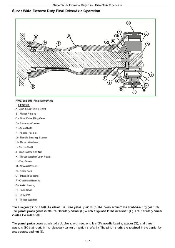
Super Wide Extreme Duty Final Drive/Axle Operation…………….459
Service Brake Operation—Single Disk…………….461
Service Brake Operation—Multiple Disk…………….462
Service Brake Operation — Dry Drum…………….464
Park Brake Operation—Manual…………….466
Park Brake Operation—SAHR…………….468
Section 04: Diagnostics…………….470
Group 200: Brake Inspection, Adjustments, Tests, and Bleeding…………….470
Adjust Park Brake—Spring Applied/Hydraulic Release…………….473
Park Brake Pressure Test…………….475
Adjust Park Brake—Manual…………….476
Brake Disk Inspection (External)…………….478
Service Brake Leak Test…………….481
Annular Brake Piston Inspection…………….484
Bleed Hydraulic Brakes…………….485
Group 210: Operational Checks…………….470
Air Test Axle Assembly…………….488
Axle Vertical Movement Check…………….489
Check Carrier Backlash…………….490
Check Ring Gear and Pinion Tooth Contact Pattern…………….491
Group 220: Differential and Axle Assembly Tests…………….470
Air Test Differential Lock Capture System…………….493
Oil Test Differential Lock Capture System…………….494
Test Differential Lock Sealing Rings with Air Boost System…………….495
Air Test Standard and Extreme Duty Axle Assembly…………….496
Air Test Axle Assembly—Super Wide Extreme Duty Axle…………….497
Differential Lock Function Test…………….499
Group 230: Troubleshooting…………….470
Troubleshoot Axle and Differential…………….506
Section 05: Tools and Other Materials…………….511
Group 300: Special Tools…………….511
27494…………….514
27498…………….515
27502…………….516
27530…………….517
27537…………….518
27540…………….519
27551…………….520
27553…………….521
D05223ST…………….522
DFRW102…………….523
DFYZ49…………….524
DFYZ50…………….525
DFYZ124…………….526
JD320…………….528
JDG22…………….529
JDG185…………….530
JDG236…………….531
JDG712C…………….532
JDG825…………….533
JDG924A…………….534
JDG926A…………….535
JDG986…………….536
JDG987…………….537
JDG1363…………….538
JDG1364…………….539
JDG1365A…………….540
JDG1366…………….541
JDG1367…………….542
JDG1846…………….543
JDG10193A…………….544
JDG10209…………….545
JDG10212…………….546
JDG10627…………….547
JDG11654…………….548
JDG11655…………….549
JDG11737…………….550
JDG15001…………….551
JDG15050…………….552
JT01610…………….553
JT01748…………….554
JT02044…………….555
JT03345…………….556
JT03455…………….557
JT03527…………….558
JT05508…………….559
JT05600…………….560
JT05706…………….561
JT07250…………….562
Group 310: Other Materials…………….512
Other Material…………….564
Section 06: Specifications…………….565
Group 400: Bolts and Cap Screws Specifications…………….565
Metric Bolt and Screw Torque Values…………….568
Unified Inch Bolt and Screw Torque Values…………….570
Group 410: Sealants and Adhesives Cross-Reference…………….565
Sealants and Adhesives Cross-Reference Chart…………….574
John Deere TeamMate II 1400 Series Inboard Planetary Axles (Worldwide Edition) Component Technical Manual (CTM138619)