Complete Repair Service Technical Manual for John Deere 770G, 770GP, 772G, and 772GP Motor Graders, with all the shop information to maintain, repair, and rebuild like professional mechanics.
John Deere 770G, 770GP, 772G, and 772GP Motor Graders workshop technical manual (repair) includes:
* Numbered table of contents easy to use so that you can find the information you need fast.
* Detailed sub-steps expand on repair procedure information
* Numbered instructions guide you through every repair procedure step by step.
* Notes, cautions and warnings throughout each chapter pinpoint critical information.
* Bold figure number help you quickly match illustrations with instructions.
* Detailed illustrations, drawings and photos guide you through every procedure.
* Enlarged inset helps you identify and examine parts in detail.
tm14079x19 – John Deere 770G, 770GP, 772G, and 772GP Motor Graders Technical Manual (Repair).pdf
tm14079x63 – Motoniveladoras 770G, 770GP, 772G y 772GP
Category: Repair
Language: Spanish
Published on 2019/08/16
English
tm14079x19 – 770G, 770GP, 772G, and 772GP Motor Graders
Published on 2019/07/11
French
tm14079x28 – Niveleuses 770G, 770GP, 772G et 772GP
Published on 2019/07/26
Portuguese
tm14079x54 – Motoniveladoras 770G, 770GP, 772G e 772GP
Published on 2019/08/16
Russian
tm14079x59 – автогрейдеров 770G, 770GP, 772G и 772GP
Published on 2019/07/26
PRODUCT DETAILS:
Total Pages: 852 pages
File Format: PDF/EPUB/MOBI/AZW (PC/Mac/Android/Kindle/iPhone/iPad; bookmarked, ToC, Searchable, Printable)
Language: English etc
TABLE OF CONTENTS…………….1
Section 00: General Information…………….16
Group 0001: Safety…………….16
Information for European Union Directives and Eurasian Economic Union Technical Regulations Compliance…………….22
Recognize Safety Information…………….26
Follow Safety Instructions…………….27
Operate Only If Qualified…………….28
Wear Protective Equipment…………….29
Avoid Unauthorized Machine Modifications…………….30
Inspect Machine…………….31
Stay Clear of Moving Parts…………….32
Avoid High-Pressure Fluids…………….33
Avoid High-Pressure Oils…………….34
Work In Ventilated Area…………….35
Avoid Static Electricity Risk When Refueling…………….36
High Debris Applications…………….38
Prevent Fires…………….39
In Case of Machine Fire…………….40
Prevent Battery Explosions…………….41
Handle Chemical Products Safely…………….42
Handle Starting Fluid Safely…………….43
Decommissioning — Proper Recycling and Disposal of Fluids and Components…………….44
Prepare for Emergencies…………….45
Clean Debris from Machine…………….46
Use Steps and Handholds Correctly…………….47
Start Only From Operator's Seat…………….48
Use and Maintain Seat Belt…………….49
Prevent Unintended Machine Movement…………….50
Avoid Work Site Hazards…………….52
Keep Riders Off Machine…………….54
Avoid Backover Accidents…………….55
Avoid Machine Tip Over and Machine Damage…………….56
Operating or Traveling On Public Roads…………….57
Inspect and Maintain ROPS…………….58
Travel Safely…………….59
Prevent Acid Burns…………….60
Add and Operate Attachments Safely…………….62
Park and Prepare for Service Safely…………….63
Service Machines Safely…………….64
Service Cooling System Safely…………….65
Remove Paint Before Welding or Heating…………….66
Make Welding Repairs Safely…………….67
Drive Metal Pins Safely…………….68
Service Tires Safely…………….69
Use Proper Lifting Equipment…………….70
Group 0003: Torque Values…………….17
Metric Bolt and Cap Screw Torque Values…………….73
Additional Metric Cap Screw Torque Values…………….75
Unified Inch Bolt and Cap Screw Torque Values…………….77
Service Recommendations for 37° Flare and 30° Cone Seat Connectors…………….80
Service Recommendations for O-Ring Boss Fittings…………….82
Service Recommendations for Flared Connections—Straight or Tapered Threads…………….84
Service Recommendations for Flat Face O-Ring Seal Fittings…………….86
O-Ring Face Seal Fittings With SAE Inch Hex Nut and Stud End for High-Pressure Service Recommendations…………….88
O-Ring Face Seal Fittings With Metric Hex Nut and Stud End for Standard Pressure Service Recommendations…………….90
O-Ring Face Seal Fittings With Metric Hex Nut and Stud End for High-Pressure Service Recommendations…………….93
Service Recommendations for Metric Series Four Bolt Flange Fitting…………….96
Service Recommendations For Inch Series Four Bolt Flange Fittings…………….98
Inch Series Four Bolt Flange Fitting for High-Pressure Service Recommendations…………….100
Service Recommendations For Non-Restricted Banjo (Adjustable) Fittings…………….102
Service Recommendations For O-Ring Boss Fittings With Shoulder…………….105
Metric 24° O-Ring Seal DIN 20078 Service Recommendations…………….108
Section 01: Wheels…………….112
Group 0110: Powered Wheels and Fasteners…………….112
Wheel Remove and Install…………….114
Tire Remove and Install…………….115
Section 02: Axles and Suspension Systems…………….118
Group 0225: Input Drive Shafts and U-Joints…………….118
Transmission-to-Rear Axle Drive Shaft Remove and Install…………….122
Transmission-to-Rear Axle Drive Shaft Disassemble and Assemble…………….124
Group 0230: Non-Powered Wheel Axles…………….118
Front Wheel Hub and Spindle Remove and Install—Non 6WD…………….130
Front Wheel Hub and Spindle Disassemble and Assemble—Non 6WD…………….134
Front Axle Remove and Install—Non 6WD…………….141
Group 0240: Powered Wheel Axle…………….118
Front Wheel Hub and Spindle Remove and Install—6WD…………….152
Front Wheel Hub and Spindle Disassemble and Assemble—6WD…………….158
Front Wheel Hub and Spindle Disassemble and Assemble With Steering Angle Sensor—6WD…………….165
6WD Drive Hub Disassemble and Assemble…………….172
Planetary Drive Disassemble and Assemble…………….174
Planetary Brake Disassemble and Assemble…………….177
6WD Bearings Remove and Install…………….186
6WD O-Ring Metal Face Seal Remove and Install…………….190
Front Axle Remove and Install—6WD…………….199
Group 0250: Axle Shaft, Bearings, and Reduction Gears…………….118
TeamMate™ II 1400 Series Inboard Planetary Axle—Use CTM138619…………….207
Rear Axle Remove and Install…………….208
Tandem and Wheel Axle Assembly Remove and Install…………….213
Tandem Wheel Axle Assembly Remove and Install…………….217
Tandem Wheel Axle Assembly Disassemble and Assemble…………….220
Tandem Pivot Disassemble and Assemble…………….225
Final Drive Axle Remove and Install…………….230
Tandem Drive Shaft Remove and Install…………….238
Drive Chain Remove and Install…………….244
Group 0260: Hydraulic System…………….118
Six-Wheel Drive (6WD) Pump Remove and Install…………….253
6WD Pump Disassemble and Assemble…………….258
6WD Charge Pump Remove and Install…………….265
6WD Engagement Manifold Remove and Install…………….266
Differential Lock Pump Remove and Install…………….269
6WD Motor Remove and Install…………….271
6WD Motor Disassemble and Assemble…………….273
Section 03: Transmission…………….277
Group 0300: Removal and Installation…………….277
DF180 Transmission…………….280
Transmission Remove and Install…………….282
Group 0360: Hydraulic System…………….277
Transmission Charge Pump Remove and Install…………….292
Section 04: Engine…………….295
Group 0400: Removal and Installation…………….295
John Deere Engine…………….297
Engine Remove and Install—Engine 6090HDW38…………….298
Engine Remove and Install—Engine 6090HDW04…………….312
Section 05: Engine Auxiliary System…………….313
Group 0510: Cooling System…………….313
Fan Blade Remove and Install…………….317
Radiator Remove and Install…………….320
Hydraulic and Differential Oil Cooler Remove and Install…………….324
Transmission Oil Cooler Remove and Install…………….327
Fuel Cooler Remove and Install…………….330
Charge Air Cooler Remove and Install…………….332
Group 0560: External Fuel Supply Systems…………….313
Fuel Tank Remove and Install…………….340
Fast Fill Fuel System Disassemble and Assemble—If Equipped…………….345
Section 07: Torsional Isolator…………….349
Group 0752: Elements…………….349
Torsional Isolator Remove and Install…………….352
Section 09: Steering System…………….354
Group 0920: Power Steering…………….354
Toe-In Check and Adjustment…………….357
Group 0960: Hydraulic System…………….354
Steering Wheel, Column, and Valve Remove and Install—Standard Controls…………….362
Steering Wheel, Column, and Valve Remove and Install—EH Controls…………….365
EH Controls Steering Canceling Valve Remove and Install…………….369
Steering Valve Disassemble and Assemble…………….371
Steering Cylinder Remove and Install…………….378
Hydraulic Cylinder Disassemble and Assemble…………….382
Wheel Lean Cylinder Remove and Install…………….383
Secondary Steering Accumulator Remove and Install—If Equipped…………….387
Section 10: Service Brakes…………….389
Group 1011: Active Elements…………….389
Service Brake Repair…………….391
Group 1060: Hydraulic System…………….389
Service Brake Valve Remove and Install…………….395
Service Brake Bleeding…………….398
Brake Accumulator Remove and Install…………….543
Section 11: Park Brake…………….401
Group 1111: Active Elements…………….401
Park Brake Repair…………….403
Section 16: Electrical System…………….404
Group 1600: Removal and Installation…………….404
Controller Remove and Install…………….407
Steering Angle Sensor Remove and Install…………….409
Replace Weather Pack™ Connector…………….413
Install Weather Pack™ Contact…………….415
Replace DEUTSCH® Connectors…………….417
Replace DEUTSCH® Rectangular or Triangular Connectors…………….419
Install DEUTSCH® Contact…………….421
Replace (Pull Type) Metri-Pack™ Connectors…………….423
Replace (Push Type) Metri-Pack™ Connectors…………….425
Replace CINCH CINCH is a trademark of the Cinch Co. Connectors…………….404
Install CINCH CINCH is a trademark of the Cinch Co. Contact…………….404
Repair 32 and 48 Way CINCH® Connectors…………….430
Section 17: Frame or Supporting Structure…………….434
Group 1740: Frame Installation…………….434
Welding On Machine…………….436
Welding Repair of Major Structure…………….437
Separate Frames at Articulation Joint…………….439
Articulation Bearing Replacement…………….445
Rear Platform Remove and Install…………….449
Section 18: Operator's Station…………….457
Group 1800: Removal and Installation…………….457
Cab Remove and Install…………….467
Cab Remove and Install—GP Machine Only…………….475
Group 1810: Operator Enclosure…………….457
Windowpanes Remove and Install…………….485
Cab Door Handle Remove and Install…………….487
Cab Door Latch Remove and Install…………….489
Rivet Nut Installation…………….491
Wiper Arm Installation…………….496
Group 1815: Pedal Assembly…………….457
Inching Pedal Remove and Install…………….501
Group 1816: Steering Tilt Console…………….457
Steering Support Console Remove and Install—Standard Controls…………….506
Steering Support Console Remove and Install—EH Controls…………….509
Console Tilt Remove and Install…………….512
Steering Tilt Assembly Remove and Install…………….515
Group 1821: Seat and Seat Belt…………….457
Seat Remove and Install…………….519
Seat Belt Remove and Install…………….522
Armrest Remove and Install…………….524
Armrest Remove and Install—EH Controls…………….525
Armrest Disassemble and Assemble—EH Controls…………….527
Standard Seat Disassemble and Assemble…………….529
Deluxe Seat Disassemble and Assemble…………….531
Air Suspension Disassemble and Assemble…………….533
Group 1830: Heating and Air Conditioning…………….457
R134a Refrigerant Cautions and Proper Handling…………….536
Flush and Purge Air Conditioning System…………….537
R134a Refrigerant Oil Information…………….539
R134a Refrigerant Recovery, Recycling, and Charging Station Installation Procedure…………….541
Accumulator Remove and Install…………….543
Recover R134a Refrigerant…………….545
Evacuate R134a System…………….546
Charge R134a System…………….548
Expansion Valve Remove and Install…………….550
Freeze Control Switch Remove and Install…………….555
Heater Control Valve Remove and Install…………….557
Blower Motor Assembly Remove and Install…………….560
Compressor Remove and Install…………….561
Condenser Remove and Install…………….564
Heater and Air Conditioner Remove and Install…………….568
Receiver-Dryer Remove and Install…………….573
Heater Control Valve Leak Check…………….575
Section 19: Sheet Metal and Styling…………….576
Group 1910: Engine Enclosure…………….576
Engine Service Doors and Side Shields Remove and Install…………….578
Engine Covers Remove and Install…………….579
Group 1921: Grille and Grille Housing…………….576
Grille Housing Remove and Install…………….589
Section 21: Main Hydraulic System…………….594
Group 2160: Hydraulic System…………….594
Hydraulic Pump Remove and Install…………….598
Hydraulic Pump Disassemble and Assemble…………….601
Hydraulic System Manifold Remove and Install…………….606
Hydraulic System Manifold Disassemble and Assemble…………….608
Soft Start Valve Remove and Install…………….610
Vacuum Pump Installation…………….611
Hydraulic Fan Pump Remove and Install…………….612
Hydraulic Fan Motor Remove and Install…………….615
Hydraulic Fan Valve Remove and Install…………….617
General Oil Cleanup Procedure…………….620
Hydraulic Component Failure Cleanup Procedure…………….623
Hydraulic Attenuator Remove and Install…………….625
Section 34: Grading Device…………….627
Group 3415: Controls Linkage…………….627
Control Linkage Remove and Install…………….631
Group 3440: Frames…………….627
Lift Arms Remove and Install…………….638
Saddle Locking Cylinder Remove and Install…………….643
Saddle Locking Pin Disassemble and Assemble…………….646
Saddle Frame Remove and Install…………….649
Blade Pitch Frame Remove and Install…………….651
Draft and Circle Frame Remove and Install…………….655
Circle Adjustment…………….660
Blade Side Shift Wear Inserts Remove and Install…………….667
Group 3450: Circle Gearbox…………….627
Circle Drive Gearbox Remove and Install…………….672
Dual Input Circle Drive Gearbox Remove and Install—If Equipped…………….674
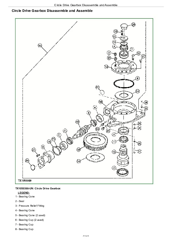
Circle Drive Gearbox Disassemble and Assemble…………….678
Circle Drive Gear Case (With Slip Clutch) Disassemble and Assemble…………….683
Dual Input Circle Drive Gearbox Disassemble and Assemble—If Equipped…………….701
Dual Input Circle Drive Gear Case (With Slip Clutch) Disassemble and Assemble—If Equipped…………….706
Circle Rotate Motor Disassemble and Assemble…………….713
Circle Rotate Sensor Remove and Install…………….731
Group 3460: Hydraulic System…………….627
Grader Control Valve Remove and Install…………….741
Draft Frame Mount Grader Control Valve Remove and Install—EH Controls…………….747
Cab Mount Grader Control Valve Remove and Install—EH Controls…………….751
Grader Control Valve Disassemble and Assemble…………….754
Midmount Scarifier Valve Section Disassemble and Assemble…………….759
Midmount Scarifier Valve Section Disassemble and Assemble—EH Controls…………….762
Blade Lift Valve Section Disassemble and Assemble…………….765
Blade Lift Valve Section Disassemble and Assemble—EH Controls…………….768
Auxiliary (With Float) Valve Section Disassemble and Assemble…………….771
Auxiliary (Without Float) Valve Section Disassemble and Assemble…………….774
Auxiliary Valve Section Disassemble and Assemble—EH Controls…………….777
Wheel Lean, Articulation, Circle Side Shift, Blade Pitch, and Blade Side Shift Valve Section Disassemble and Assemble…………….780
Wheel Lean, Articulation, Circle Side Shift, Blade Pitch, Blade Side Shift, and Steering Valve Section Disassemble and Assemble—EH Controls…………….783
Circle Rotate Valve Section Disassemble and Assemble…………….786
Circle Rotate Valve Section Disassemble and Assemble—EH Controls…………….789
Return Check Poppets Disassemble and Assemble…………….791
Rotary Manifold Remove and Install…………….792
Rotary Manifold Disassemble and Assemble…………….795
Blade Lift, Blade Pitch, and Circle Side Shift Cylinders Remove and Install…………….797
Blade Side Shift Cylinder Remove and Install…………….799
Articulation Cylinders Remove and Install…………….802
Section 42: Ground Conditioning Tool…………….804
Group 4240: Frames…………….804
Midmount Scarifier Remove and Install…………….813
Midmount Scarifier Cylinder Remove and Install…………….821
Ripper Remove and Install…………….823
Ripper Cylinders Remove and Install…………….826
Section 99: Dealer Fabricated Tools…………….829
Group 9900: Dealer Fabricated Tools…………….829
DF1057—Axle Adjusting Tool…………….832
DFT1151—Outboard Bearing Driver…………….834
DFT1152—Inboard Bearing Driver…………….835
DFT1225—Rolling Torque Measurement Tool…………….836
DFT1282—King Pin Torque Adapter…………….837
DFT1308 Transmission Support Bracket…………….838
DFT1310—Cab Mount Control Valve Support Bracket…………….840
DFT1376 Fan Hub Puller…………….841
DFT1380 Lift Bracket…………….842
DFT1382 Lift Bracket…………….847
DFT1382-1 Attachment…………….849
John Deere 770G, 770GP, 772G, and 772GP Motor Graders Repair Service Manual (TM14079X19)