INSTANT DOWNLOAD
Complete Diagnosis & Tests Technical Manual with electrical wiring diagrams for John Deere Tractors 6010, SE6010, 6110, SE6110, 6210, 6310, 6410, SE6410, 6510, SE6510, 6610, SE6610, 6810, 6910, 6910S, with workshop information to maintain, test, repair, and service like professional mechanics.
John Deere 2WD or MFWD Tractors 6010, 6110, 6210, 6310, 6410, 6510, 6610, 6810, 6910, 6910S and SE workshop Diagnosis Tests technical manual includes:
* Numbered table of contents easy to use so that you can find the information you need fast.
* Detailed sub-steps expand on repair procedure information
* Numbered instructions guide you through every repair procedure step by step.
* Troubleshooting and electrical service procedures are combined with detailed wiring diagrams for ease of use.
* Notes, cautions and warnings throughout each chapter pinpoint critical information.
* Bold figure number help you quickly match illustrations with instructions.
* Detailed illustrations, drawings and photos guide you through every procedure.
* Enlarged inset helps you identify and examine parts in detail.
TM4552 English – 6010, 6110, 6210, 6310, 6410, 6510, 6610, 6810, 6910, 6910s and se tractors Technical Manual.pdf
tm4551 German – Traktoren 6010 bis 6910 und SE-Traktoren
tm4553 French – Tracteurs 6010 à 6910S et tracteurs SE
tm4555 Italian – Funzionamento e prove trattori 6010 – 6910S e trattori SE
tm4556 Dutch – Trekkers 6010 T/M 6910S en SE-modellen Werking en Controles
tm4557 Swedish – Traktorer 6010 till 6910S och SE-traktorer Funtion och kontroller
tm4570 Czech – Traktory rady 6010 az 6910S a traktory SE Cinnost a testy Cast 1 ze 2: oddily 210 az 245-BCU ( – 266766)
tm4660 Finnish – Traktorit 6010 – 6910S ja SE-traktorit Toiminta ja testaukset
tm4661 Greek – 6010 – 6910S (210 – 245-BCU)
tm4570-2 Czech – Traktory rady 6010 az 6910S a traktory SE Cinnost a testy Cast 1 ze 2: oddily 245 az 299-BCU ( – 266766)
tm4682 Dutch – TECHNISCH HANDBOEK Trekkers 6010 t/m 6910S en SE-modellen Diagnose
tm4556-2 Dutch – Trekkers 6010 T/M 6910S en SE-modellen Werking en Controles Deel 2 van 3: Hoofdstuk 240-15A t/m 245
tm4556-3 Dutch – Trekkers 6010 T/M 6910S en SE-modellen Werking en Controles Deel 2 van 3: Hoofdstuk 250 t/m 299
tm4556_part1 Dutch – Trekkers 6010 t/m 6910S en SE-modellen Werking en controles Deel 1 van 3: Hoofdstuk 210 t/m 240-15
tm4556_part2 Dutch – Trekkers 6010 t/m 6910S en SE-modellen Werking en controles Deel 2 van 3: Hoofdstuk 240-15A t/m 245
tm4556_part3 Dutch – Trekkers 6010 t/m 6910S en SE-modellen Werking en controles Deel 3 van 3: Hoofdstuk 250 t/m 299
tm4602 Czech – Traktory 6801 a 6910 Opravy
Total Pages: 5,232 pages
File Format: PDF (PC/Mac/Android/Kindle/iPhone/iPad; bookmarked, ToC, Searchable, Printable)
Language: English
MAIN SECTIONS
Foreword
Safety
Safety
Service Code Diagnostics
BCU Service Code Diagnostics
BIF Service Code Diagnostics
ECU (Level 1 with LUCAS injection pump) Service Code Diagnostics
ECU (Level 4 with BOSCH VP44 injection pump) Service Code Diagnostics
HCU Service Code Diagnostics
PCU Service Code Diagnostics
PEC Service Code Diagnostics
PLC Service Code Diagnostics
RCU Service Code Diagnostics
SFA Service Code Diagnostics
TCU Service Code Diagnostics
UIC Service Code Diagnostics
Observable Symptoms
Electrical System
PowrQuad, PowrQuad Plus and AutoQuad Transmissions
Drive System (except transmission)
Steering and Brakes
Hydraulic System
Engine
Tests
Fuel, Air Intake and Cooling Systems
System Diagnosis
Tests and Adjustments
Fuel System
Air Intake System
Cooling System
Cold-Weather Starting Aids
Electrical System
General
Functional Schematics and Wiring Diagrams (6010-6910S)
Functional Schematics and Wiring Diagrams (SE Tractors)
Functional Schematics and Wiring Diagrams (2-Post ROPS)
Functional Schematics and Wiring Diagrams (AutoPowr)
Circuit Testing (6010-6910S with Cab)
Sub-System Diagnostics (SE Tractors)
Sub-System Diagnostics (2-Post ROPS)
Circuit Testing (AutoPowr Transmission)
Data BUS Systems
Data BUS Systems –– Diagnosis
Adjustments
Component Testing
Electronic Control Units
Operation and General Information on Diagnostics
BCU References
BIF References
ECU (Level 1) References
HCU References
PCU References
PEC References
PLC References
RCU References
SFA References
TCU References
UIC References
SyncroPlus Transmission
Operational Checkout
Troubleshooting
Tests and Adjustments
SyncroPlus Transmission Operation
Perma Clutch II
Gear Transmission
Creeper Transmission
Range Transmission
Power Reverser Transmission
Operational Checkout
Troubleshooting
Test and Adjustments
Power Reverser Operation
Power Reverser Module
Gear Transmission
Power Shift Transmission
Operational Checkout
Troubleshooting
Adjustments
Theory of Operation
AutoPowr Transmission
Diagnosis – UIC
Diagnosis – TCU
Diagnosis – PLC
Tests and Adjustments
Operation
PowrQuad, PowrQuad Plus and AutoQuad II Transmissions
Operational Checkout
POWRQUAD™Transmission Check
Troubleshooting on PowrQuad Plus and AutoQuad II
Tests and Adjustments
PowrQuad Transmission Operation
PowrQuad Plus and AutoQuad II Transmission Operation
Creeper Transmission
Range Transmission
Drive Systems
Operational Checkout
Troubleshooting
Tests
Front-Wheel Drive Clutch
Differential
Final Drives
Rear PTO Options
Front PTO
Steering and Brakes
Operational Checkout
Troubleshooting
Tests and Adjustments
Hydrostatic Steering
Hydraulic Brakes
Handbrake
Hydraulic Trailer Brake
Air Brake System
Hydraulic System
Operational Checkout
PFC Hydraulic System Troubleshooting
PC Hydraulic System Troubleshooting
Tests and Adjustments
PFC Hydraulic System
Charge Oil Pump
Hydraulic Pumps
Valves, Oil Cooler and Filter
Rockshaft
Selective Control Valves and Couplers
Independent Control Valve (ICV)
PC Hydraulic System and Components
Miscellaneous
TLS Front Axle Operational Checkout
TLS Front Axle Troubleshooting
TLS Front Axle Tests and Adjustments
TLS Front Axle Operation
Operators Cab
Operational Checkout
Air Conditioner Troubleshooting
Ventilation and Heater Troubleshooting
Operator’s Seat Troubleshooting
Air Conditioner Operation
Ventilation and Heating Operation
Special Tools (Dealer-Fabricated)
tm4552 – 6010, 6110, 6210, 6310, 6410, 6510, 6610, 6810, 6910, 6910s and se tractors
Table of Contents
Foreword
Section 210: Safety
Group 05: Safety
Recognize Safety Information
“Important” – Information
“Note” – Information
Prevent Machine Runaway
Handle Fluids Safely-Avoid Fires
Prevent Battery Explosions
Prepare for Emergencies
Prevent Acid Burns
Avoid High-Pressure Fluids
Service Cooling System Safely
Remove Paint Before Welding or Heating
Avoid Heating Near Pressurized Fluid Lines
Work In Ventilated Area
Wear Protective Clothing
Practice Safe Maintenance
Park Machine Safely
Use Proper Lifting Equipment
Construct Dealer-Made Tools Safely
Support Machine Properly
Work in Clean Area
Illuminate Work Area Safely
Service Machines Safely
Use Proper Tools
Service Tires Safely
Service Front-Wheel Drive Tractor Safely
Safety Information – Air Brake System
Avoid Eye Contact with Radar
Keep ROPS Installed Properly
Replace Safety Signs
Dispose of Waste Properly
Live With Safety
Section 211: Service Code Diagnostics
Group BCU: BCU Service Code Diagnostics
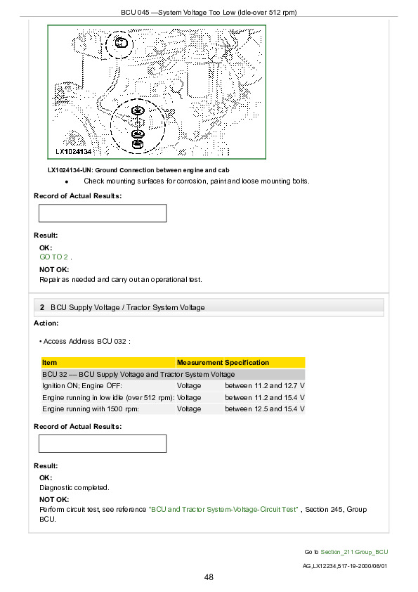
BCU 045-System Voltage Too Low (Idle over 512 rpm)
BCU 046-System Voltage Too Low (idle over 1500 rpm)
BCU 047-System Voltage Too High (Engine Running)
BCU 055-Handbrake Failure
BCU 072-Rear PTO Circuit / Switch Error
BCU 073-Defective Rear PTO Solenoid
BCU 075-Rear PTO Speed Not Present After PTO ON
BCU 080-Differential Lock Still Activated After deactivation
BCU 081-Defective Differential Lock Solenoid
BCU 085-MFWD Control Switch Error
BCU 086-Faulty MFWD Solenoid
BCU 106-Internal BCU Fault
BCU 130-Turn Signal Switch Fault
BCU 131-Turn Signal Circuit Fault
BCU 132-Defective Hazard Warning Light Power Supply Fuse F102 (20A)
BCU 133-PTO Remote Failure
BCU 134-HMS Circuit Fault
Group BIF: BIF Service Code Diagnostics
BIF 001-Fuel Level Sensor Circuit
BIF 002-Fuel Level Sensor Circuit
BIF 003-Fuel Level Sensor Circuit
BIF 010-Engine Coolant Temperature High
BIF 011-Engine Coolant Temperature Very High
BIF 012-Coolant Temperature Sensor-Circuit Open
BIF 013-Coolant Temperature Sensor-Circuit Shorted
BIF 015-Transmission Oil Temperature High
BIF 016-Transmission Oil Temperature Very High
BIF 017-Transmission Oil Temperature Sensor-Circuit Open
BIF 018-Transmission Oil Temperature Sensor-Circuit Shorted
BIF 021-Engine Oil Pressure Low (Pressure Switch)
BIF 023-Missing Engine Speed Signal
BIF 026-Transmission Oil Pressure Low
BIF 030-Engine Air Filter Restricted
BIF 035-Transmission and Hydraulic Oil Filter Restricted
BIF 036-Hydraulic Oil Filter Service Alert Alarm
BIF 045-System Voltage Too Low (Idle over 512 rpm)
BIF 046-System Voltage Too Low (idle over 1500 rpm)
BIF 047-System Voltage Too High (Engine Running)
BIF 049-Alternator D+ voltage too low (Idle over 512 rpm)
BIF 050-Alternator D+ voltage too low (idle over 1500 rpm)
BIF 051-Alternator D+ voltage too high
BIF 106-Internal BIF Fault
BIF 135-BCU Timing Signal not received
BIF 136-Open CCD BUS Lines
BIF 137-Open in CAN BUS Lines
BIF 140-Rear PTO Speed Warning
Group ECU (Level 1): ECU (Level 1 with LUCAS injection pump) Service Code Diagnostics
ECU 011-Foot Throttle Potentiometer ECU Input Voltage Too High
ECU 012-Foot Throttle Potentiometer ECU Input Voltage Too Low
ECU 013-Cruise Control Potentiometer Input Voltage Too High
ECU 014-Cruise Control Potentiometer Input Voltage Too Low
ECU 018-Coolant Temperature Sensor Input Voltage Too High
ECU 019-Coolant Temperature Sensor Input Voltage Too Low
ECU 021-Sensor Supply Voltage Too High
ECU 022-Sensor Supply Voltage Too Low
ECU 039-Engine Speed Input Signal Fault
ECU 041-Missing Engine Start Signal
ECU 042-High Idle Speed Too High
ECU 046-Engine Start Signal Always High
ECU 055-ECU detects Not Related CAN BUS Information
ECU 064-Hand Throttle Calibration Failed
ECU 065-Hand Throttle Calibration Value Error
ECU 081-Internal ECU Failure (Pump Current Feedback Voltage Too High)
ECU 082-Internal ECU Failure (Pump Current Feedback Voltage Too Low)
ECU 083-Injection Pump (Unstable Current Regulation for Actuator Magnet)
ECU 084-Injection Pump (Actuator Magnet Current Regulation cannot be controlled)
ECU 085-Injection Pump (Actuator Magnet Current Regulation Too High While Engine is OFF)
ECU 091-Ground Speed Signal Missing Or Incorrect (CAN BUS Message)
ECU 092-Ground Speed Input in ECU and CAN BUS Message Ground Speed Are Different
ECU 093-Internal Miscalculation (based on Service Codes ECU 091 and ECU 092)
Group ECU (Level 4): ECU (Level 4 with BOSCH VP44 injection pump) Service Code Diagnostics
ECU 011- (000091.03) Foot Throttle Potentiometer Input Voltage Too High
ECU 012-(000091.04) Foot Throttle Potentiometer Input Voltage Too Low
ECU 013-(000028.03) Cruise Control Potentiometer Input Voltage Too High
ECU 014-(000028.04) Cruise Control Potentiometer Input Voltage Too Low
ECU 015-(000029.03) Hand Throttle Potentiometer Input Voltage Too High
ECU 016-(000029.04) Hand Throttle Potentiometer Input Voltage Too Low
ECU 018-(000110.03) Coolant Temperature Sensor Input Voltage Too High
ECU 019-(000110.04) Coolant Temperature Sensor Input Voltage Too Low
ECU 021-(001079.03) Sensor Supply Voltage too High
ECU 022-(001079.04) Sensor Supply Voltage too Low
ECU 023-(000100.03) Oil Pressure Input Voltage too High
ECU 024-(000100.04) Oil Pressure Input Voltage too Low
ECU 027-(000094.03) Fuel Pressure Input Voltage too High
ECU 028-(000094.04) Fuel Pressure Input Voltage too Low
ECU 031-(001080.03) Sensor Supply Voltage too High
ECU 032-(001080.04) Sensor Supply Voltage too Low
ECU 033-(000174.15) Fuel Temperature Is Above Normal Least Severe
ECU 034-(000629.19) ECU To Pump Communication Error
ECU 035-(001077.07) Pump Attempting to Fuel With 0 Command
ECU 036-(001077.31) VP44 Initiated Engine Protection
ECU 037-(000632.02) Fuel Shut Off Error Condition Detected
ECU 038-(000637.08) Crank Signal Missing
ECU 039-(000637.02) Noise Detected On Crank Signal
ECU 039-(000637.10) Crank Pattern Error
ECU 042-(000190.00) High Idle Speed Too High,
ECU 043-(000636.08) Event Sensor Signal Missing
ECU 044-(000636.02) Noise Detected On Event Sensor Signal
ECU 044-(000636.10) Event Sensor Pattern Error
ECU 055-(000639.02) ECU Detects Not Related CAN BUS Information
ECU 057-(000094.18) Fuel Pressure Too Low – Moderately Severe Level
ECU 058-(000094.01) Fuel Pressure Too Low – Most Severe Level
ECU 062-(000110.16) Engine Coolant Temperature Too High – Moderately Severe Level
ECU 063-(000110.00) Engine Coolant Temperature Too High – Most Severe Level
ECU 066-(001076.02) VP44 Detected Defect
ECU 067-(000174.00) Fuel Temperature Is Above Normal – Most Severe Level
ECU 068-(001077.11) VP44 Input Voltage Out Of Range
ECU 071-(000174.16) Fuel Temperature Is Above Normal – Moderately Severe Level
ECU 074-(000100.18) Oil Pressure Too Low – Moderately Severe Level
ECU 075-(000100.01) Oil Pressure Too Low – Most Severe Level
ECU 076-(000627.04) ECU Unswitched Power Fault
ECU 077-(000898.09) CAN Speed Request Not Valid Or Not Received
ECU 086-(000632.05) ECU Fuel Shut Off Non-Functional
ECU 087-(001078.11) Pump Speed Does Not Match Engine Speed
ECU 089-(001485.02) Pump Power Relay Fault
ECU 091-(000084.02) Ground Speed Signal Missing Or Incorrect (CAN BUS Message)
ECU 092-(000810.02) Ground Speed Signal in ECU and CAN BUS Message Ground Speed Are Different
ECU 093-(001069.02) Internal Miscalculation (Based On Service Codes ECU 091 and ECU 092)
ECU 094-(001078.31) VP44 Unable To Achieve Desired Timing
ECU 095-(001078.07) VP44 and ECU Timing Measurement Do Not Agree
ECU 096-(001077.19) VP44 Detected CAN BUS Failure
ECU 097-(001077.12) VP44 Self Test Error
ECU 098-(000174.31) Fuel Temperature Sensor In The Pump Out Of Range
001569.31- Fuel Derate
000189.00- Engine Speed Derate
000629.13- ECU Error
Group HCU: HCU Service Code Diagnostics
HCU 022-System Voltage not in Specification
HCU 027-Calibration not Successful
HCU 028-Calibration Memory Failure
HCU 029-Calibration Memory Failure
HCU 030-Insignificant Fault that has no effect on Tractor Operation
HCU 041-Stepper Motor Circuit open
HCU 042-Stepper Motor Circuit open
HCU 043-Stepper Motor Circuit shorted
HCU 044-Stepper Motor Circuit shorted
HCU 045-Potentiometers and Position Sensor Supply Voltage Out of Range
HCU 046-Draft Sensor Supply voltage Out of Range
HCU 049-Raise/ Lower Rocker Switch Circuit
HCU 050-Stepper Motor Deadband out of range
HCU 051-(L.H.) Draft Sensor Signal Circuit
HCU 052-(R.H.) Draft Sensor Signal Circuit
HCU 053-Load/ Depth Control Potentiometer Circuit
HCU 054-Hitch Control Lever Potentiometer Circuit
HCU 055-Rockshaft Position Sensor Circuit
HCU 056-Raise Limit Control Potentiometer
HCU 057-Rate-of-Drop Control Potentiometer Circuit
HCU 058-Remote Control Switch Circuit
HCU 239-Circuit fault during Calibration
HCU 241-Hitch Position Sensor Circuit fault during Calibration
HCU 242-Hitch Position Sensor Circuit fault during Calibration
HCU 250-(R.H.) Draft Sensor Circuit out of specification during calibration
HCU 251-(R.H.) Draft Sensor Circuit out of specification during calibration
HCU 252-(R.H.) Draft Sensor Circuit out of specification during calibration
HCU 253-(L.H.) Draft Sensor Circuit out of specification during calibration
HCU 254-(L.H.) Draft Sensor Circuit out of specification during calibration
HCU 255-(L.H.) Draft Sensor Circuit out of specification during calibration
Group PCU: PCU Service Code Diagnostics
PCU 004-Top Speed Is Not Calibrated In The PCU
PCU 007-Microprocessor Ran Out Of Execution Time
PCU 008-Manifold Pressure Sensor Input Voltage Out Of Range
PCU 009-Hydraulic Oil Temperature Message Missing
PCU 010-Transmission And Engine Oil Pressure Message Missing
PCU 011-Oil Temperature Is Cold
PCU 012-Transmission Oil Pressure Too Low
PCU 016-Engine Running Too Unevenly During Calibration
PCU 018-Encoder Fault Detected In Diagnostic Mode
PCU 020-Tractor Model Is Not Calibrated Correctly
PCU 021-PCU Addresses Not Calibrated
PCU 023-Engine Speed Sensor Missing
PCU 027-PCU Not Calibrated Correctly Or Calibration Failed
PCU 028-B4 Element Not Calibrated Successfully
PCU 030-Clutch Engaged And Disengaged Switch Conflict (Both Closed At Same Time)
PCU 031-Clutch Engaged And Disengaged Switches OPEN For Too Long (“Riding” The Clutch)
PCU 038-Internal Failure Of PCU
PCU 039-Fault in Reverse Switch Circuit
PCU 040-Fault in Forward Switch Circuit
PCU 041-Forward and Reverse Switch Circuit Conflict
PCU 042-Forward Switch Closed, But Gear Encoder Indicates Reverse
PCU 043-Reverse Switch Closed, But Gear Encoder Indicates Forward
PCU 044-Encoder Indicates A Gear, But Enable Relay Indicates Neutral
PCU 045-Encoder Indicates Neutral, But Enable Relay Indicates NOT Neutral
PCU 047-Shift Lever Has Been Between Neutral And Gear For Too Long
PCU 048-System Voltage Out Of Range
PCU 050-Shift Lever In Gear At Ignition ON
PCU 051-No Tractor Movement Detected With Engine Running
PCU 058-Tractor Movement Detected In Calibration Mode
PCU 063-Controller Error, Shift Pressure Calculation Overflow
PCU 065-Internal PCU Failure During Normal Operation
PCU 066-Shift Lever In Gear At Power Up
PCU 067-Failed Start-In-Gear Circuit
PCU 068-Encoder Fault During Normal Operation
PCU 069-Controller Not Calibrated
Group PEC: PEC Service Code Diagnostics
PEC 028-Calibration Memory Failure
PEC 051-E-ICV No.1 Potentiometer – Voltage Out Of Specification
PEC 052-E-ICV No.2 Potentiometer – Voltage Out Of Specification
PEC 053-E-ICV No.3 Potentiometer – Voltage Out Of Specification
PEC 059-E-ICV Multi-Function Lever – Supply Voltage Out Of Specification
PEC 060-E-ICV Transport Lock Switch Fault
PEC 061-E-ICV Multi-Function Lever Interlock Switch Fault
PEC 070-Upshift or Downshift Switch Pressed With Ignition ON
PEC 071-AutoQuad Switch Or Power/ECO Mode Switch Failure At Power Up
PEC 106-Internal PEC Fault
PEC 128-Stepper Motor Driver (SMD0) Supply Voltage Out Of Range
PEC 129-Stepper Motor Driver (SMD0) Short In/To Stepper Motor (M15)
PEC 130-Stepper Motor Driver (SMD0) Internal Fault
PEC 131-Excessive Deviation Of Stepper Motor Switch Signal And Stepper Motor Position
PEC 132-Stepper Motor Position Switch Problem
PEC 133-Stepper Motor Driver (SMD0) Open Lead To Stepper Motor
PEC 134-Incorrect Internal Voltage Of Stepper Motor Driver
PEC 136-E-ICV No.1 Stepper Motor Driver (SMD) Power Supply Voltage Out Of Spec
PEC 137-E-ICV No.1 Stepper Motor Driver (SMD) Short in/to Stepper Motor
PEC 138-E-ICV No.1 Stepper Motor Driver (SMD) Internal Fault
PEC 141-E-ICV No.1 Stepper Motor Driver (SMD) Open Lead to Stepper Motor
PEC 144-E-ICV No.2 Stepper Motor Driver (SMD) Power Supply Voltage Out Of Spec
PEC 145-E-ICV No.2 Stepper Motor Driver Short in/to Stepper Motor
PEC 146-E-ICV No.2 Stepper Motor Driver (SMD) Internal Fault
PEC 149-E-ICV No.2 Stepper Motor Driver (SMD) Open Lead to Stepper Motor
PEC 152-E-ICV No.3 Stepper Motor Driver (SMD) Power Supply Voltage Out Of Specification
PEC 153-E-ICV No.3 Stepper Motor Driver (SMD) Short in/to Stepper Motor
PEC 154-E-ICV No.3 Stepper Motor Driver (SMD) Internal Fault
PEC 157-E-ICV No.3 Stepper Motor Driver (SMD) Open Lead to Stepper Motor
PEC 200-Stepper Motor Driver (SMD0) Initialization Unsuccessful
PEC 201-E-ICV No.1 Stepper Motor Driver (SMD) Initialization unsuccessful
PEC 202-E-ICV No.2 Stepper Motor Driver (SMD) Initialization unsuccessful
PEC 203-E-ICV No.3 Stepper Motor Driver (SMD) Initialization unsuccessful
PEC 204-up to PEC 206 –– (E-ICV) Incorrect Calibration Value Stored in PEC
PEC 207-(E-ICV) Incorrect Calibration Value Stored in PEC
PEC 210-No Information On Ground Speed At The BUS Line After Engine Started
PEC 219-CAN BUS Inoperative
PEC 220-Stepper Motor Driver Fails During Operation
PEC 221-E-ICV No.1 Stepper Motor Driver (SMD) Not Responding to PEC Command
PEC 222-E-ICV No.2 Stepper Motor Driver (SMD) Not Responding to PEC Command
PEC 223-E-ICV No.3 Stepper Motor Driver (SMD) Not Responding to PEC Command
PEC 230-Stepper Motor Driver Address Pin Problem
Group PLC: PLC Service Code Diagnostics
PLC 010-Sender for Transmission Output Speed (B84), Short to Ground
PLC 012-Transmission Output Speed Sender (B84), Open or Shorted Circuit
PLC 016-Park Lock Pressure Sensor (B90), Shorted Circuit
PLC 017-Park Lock Pressure Sensor (B90), Short to Ground or Open Circuit
PLC 020-Park Lock Solenoid Valve (Y15-2), Short to Ground or Shorted Circuit
PLC 021-Park Lock Solenoid Valve (Y15-2), Open Circuit
PLC 030-TCU Command Invalid, Incorrect or Not Logical
PLC 040-System Voltage Too Low (Less Than 9 Volts)
PLC 050-Acoustic Alarm K202, Open Circuit or Shorted Circuit at Power Supply Line
PLC 051-Acoustic Alarm K202, Shorted Circuit
PLC 061-Signals Received from the Reverse Drive Lever Do Not Agree With the CAN BUS Command from the TCU
PLC 101-Power Supply Line for Park Lock Pressure Sensor, Short to Ground
PLC 102-Power Supply Line for Park Lock Pressure Sensor, Shorted Circuit
PLC 106-Internal Fault in Controller
PLC 240-Controller Connected to Wrong Connector on Harness
Group RCU: RCU Service Code Diagnostics
RCU 015-Fault In Detent Solenoid Circuit
RCU 017-Insignificant Fault That Has No Effect On Tractor Operation
RCU 019-Parking Switch And Reverse Lockout Switch
RCU 025-Fault In Detent Solenoid Circuit
RCU 027-Enable Switch Indicates No Pressure
RCU 029-Enable Pressure Switch Indicates Pressure, But Pressure Is Actually Zero (Diagnostic Mode Only)
RCU 031-Fault In Enable Solenoid Circuit
RCU 032-Park Position, But Valid Neutral Signal Is Missing
RCU 034-Reverse Drive Lever Remains In Direction Too Long While Range Lever Is In “Park” (Diagnostic Mode Only)
RCU 040-Forward And Reverse Switches Open, But Not-Neutral Switch Is Closed
RCU 041-Forward And Reverse Switches Closed At Same Time
RCU 042-Forward Switch Closed, But Not-Neutral Switch Open
RCU 043-Reverse Switch Closed, But Not-Neutral Switch Open
RCU 044-Not-Neutral Relay Open, But Not-Neutral Switch Closed
RCU 045-Direction Of Travel Is Selected, But Enable Solenoid Is Still Closed
RCU 047-No Neutral Signal After Engine Is Started
RCU 048-System Voltage Too Low
RCU 051-Reverse Drive Lever In Direction, But Neutral Start Switch Indicates Neutral
RCU 052-Tractor With Reverse Lockout: Range Selected For Reverse Travel Is Too High
RCU 053-Reverser Drive Lever In Neutral, But Neutral Start Switch Indicates Not Neutral
RCU 055-Enable Solenoid Stuck In Closed Position
RCU 056-Reverser Drive Lever In Forward Or Reverse When Engine Is Started
RCU 057-Transmission Enable Voltage Too Low During Operation
RCU 058-Transmission Enable Voltage Too Low When Engine Is Started
RCU 064-Fault In Memory Of RCU
RCU 065-Fault In RCU
RCU 067-Neutral Start Switch Indicates Not-Neutral Without Cause
Group SFA: SFA Service Code Diagnostics
SFA 027-Incorrect Calibration (Calibration Stopped)
SFA 028-SFA Controller Never Calibrated Or Calibration Memory Failure
SFA 029-Diagnostic Fuse Removed Before Calibration Completed
SFA 031-Failure In SFA Controller (EEPROM)
SFA 041-Internal SFA Controller Malfunction For Valve No. 1 (Y10)
SFA 042-Short To Ground In Circuit Between SFA And Solenoid Valve No. 1 (Y10)
SFA 043-Open Or Shorted Circuit Between SFA And Solenoid Valve No. 1 (Y10)
SFA 044-Internal SFA Controller Malfunction For Valve No. 2 (Y11)
SFA 045-Short To Ground In Circuit Between SFA And Solenoid Valve No. 2 (Y11)
SFA 046-Open Or Shorted Circuit Between SFA And Solenoid Valve No. 2 (Y11)
SFA 048-SFA Controller Commands “DOWN” But TLS Front Drive Axle Moves “UP” During Calibration
SFA 049-SFA Commands “UP” But TLS Front Drive Axle Moves “DOWN” During Calibration
SFA 060-During Calibration, No Cylinder Operation For 80 Seconds After Commanded To Move By SFA Controller
SFA 061-Not During Calibration, No Cylinder Operation For 60 Seconds After Commanded To Move By SFA Controller
SFA 062-While Driving, No Cylinder Operation For 60 Seconds After Commanded To Move By SFA Controller
SFA 063-Position Sensor Supply Voltage Too High
SFA 064-Position Sensor Supply Voltage Too Low
SFA 065-During Downward Movement: Sensor Output Signal Less Than 0.25 Volt
SFA 066-Moved Fully DOWN And Position Sensor Output Voltage Has Not Fallen Below 2.0 Volts
SFA 067-During Upward Movement: Sensor Output Signal More Than 4.75 Volts
SFA 068-Moved Fully UP And Position Sensor Output Voltage Has Not Exceeded 3.0 Volt
SFA 069-Sensor Output Voltage Out Of Range (Tolerance Range: 2-3 Volt) For Axle Mid Position
SFA 071-Engine Speed Signal Missing From CCD BUS Line
SFA 072-Ground Speed Signal Missing From CCD BUS Line
SFA 073-Ground Speed Signal Interrupted While Tractor In Motion
SFA 075-Internal SFA Control Unit Failure
SFA 076-Engine Speed Signal Missing From CCD BUS Line While Tractor in Motion
Group TCU: TCU Service Code Diagnostics
TCU 019-Fault at Clutch Pedal Sensors
TCU 020-Fault in Transmission Enable Circuit
TCU 024-Oil Temperature Sender, Shorted to Ground
TCU 032-Power Supply to Solenoid Valves for Forward and Reverse Travel, Shorted Circuit
TCU 033-Power Supply to Solenoid Valves for Range Elements, Shorted Circuit
TCU 040-Oil Temperature Sender, Shorted or Open Circuit
TCU 048-Transmission Input Speed Sender (B61), Short to Ground
TCU 049-Transmission Output Speed Sender (B63), Short to Ground
TCU 050-Hydrostatic Speed Sending Unit (B62), Short to Ground in Channel 1
TCU 052-Hydrostatic Speed Sending Unit (B62), Short to Ground in Channel 2
TCU 056-Transmission Input Speed Sender (B61), Shorted or Open Circuit
TCU 057-Transmission Output Speed Sender (B63), Shorted or Open Circuit
TCU 058-Hydrostatic Speed Sending Unit (B62), Shorted or Open Circuit in Channel 1
TCU 060-Hydrostatic Speed Sending Unit (B62), Shorted or Open Circuit in Channel 2
TCU 064-TCU Registers Implausible Drop in Speed at Transmission Input Speed Sender (B61)
TCU 069-TCU Registers an Implausible Drop in Speed at the PLC’s Transmission Output Speed Sender (B84)
TCU 070-PLC’s Sending Unit for Transmission Output B84 is Defective
TCU 072-TCU Transmission Input Speed and ECU Engine Speed Do Not Match
TCU 073-Transmission Output Speed Sending Unit (B63), Channels 1 and 2 Do Not Match
TCU 074-Hydrostatic Speed Sending Unit (B62), Speed in Channel 1 Lower than in Channel 2
TCU 076-Hydrostatic Speed Sending Unit (B62), Speed in Channel 2 Lower than in Channel 1
TCU 077-Transm. Input Speed (B61), Hydrostatic Speed (B62) and Transmission Output Speed (B63) Do Not Match
TCU 079-Current Strength at Proportional Solenoids of Hydrostatic Unit Do Not Match with Calculated Speed
TCU 080-Fault in Warning Light Circuit
TCU 081-C1 Solenoid Valve, Open Circuit
TCU 082-C2 Solenoid Valve, Open Circuit
TCU 083-C3 Solenoid Valve, Open Circuit
TCU 084-C4 Solenoid Valve, Open Circuit
TCU 085-BG Solenoid Valve, Open Circuit
TCU 086-Park Lock Solenoid Valve (Y15-1), Open Circuit
TCU 088-Proportional Solenoid Y1 (Hydrostatic Unit Control Valve), Open Circuit
TCU 089-Proportional Solenoid Y2 (Hydrostatic Unit Control Valve), Open Circuit
TCU 090-Proportional Valve for Forward Clutch (CF), Open Circuit
TCU 091-Proportional Valve for Reverse Clutch (CR), Open Circuit
TCU 097-C1 Solenoid Valve, Short to Ground
TCU 098-C2 Solenoid Valve, Short to Ground
TCU 099-C3 Solenoid Valve, Short to Ground
TCU 100-C4 Solenoid Valve, Short to Ground
TCU 101-BG Solenoid Valve, Short to Ground
TCU 102-Park Lock Solenoid Valve (Y15-1), Short to Ground
TCU 104-Proportional Solenoid Y1 (Hydrostatic Unit Control Valve), Short to Ground
TCU 105-Proportional Solenoid Y2 (Hydrostatic Unit Control Valve), Short to Ground
TCU 106-Proportional Valve for Forward Clutch (CF), Short to Ground
TCU 107-Proportional Valve for Reverse Clutch (CR), Short to Ground
TCU 113-C1 Solenoid Valve, Shorted Circuit
TCU 114-C2 Solenoid Valve, Shorted Circuit
TCU 115-C3 Solenoid Valve, Shorted Circuit
TCU 116-C4 Solenoid Valve, Shorted Circuit
TCU 117-BG Solenoid Valve, Shorted Circuit
TCU 118-Park Lock Solenoid Valve (Y15-1), Shorted Circuit
TCU 120-Proportional Solenoid Y1 (Hydrostatic Unit Control Valve), Shorted Circuit
TCU 121-Proportional Solenoid Y2 (Hydrostatic Unit Control Valve), Shorted Circuit
TCU 122-Proportional Valve for Forward Clutch (CF), Shorted Circuit
TCU 123-Proportional Valve for Reverse Clutch (CR), Shorted Circuit
TCU 128-System Voltage Too High (Over 16 Volts)
TCU 129-System Voltage Too Low (Less Than 9 Volts)
TCU 132-Fault in the Internal Transmission Power Supply (VPS)
TCU 136-Control Unit, Wrong Software Version
TCU 137-Internal Fault in Control Unit
TCU 138-Internal Fault in Control Unit
TCU 139-Control Unit Connected to the Wrong Harness Connector
TCU 140-Incorrect Value Input in TCU
TCU 146-TCU Transmission Speed Signal (B63) and PLC Transmission Speed Signal (B84) Do Not Match
TCU 147-Fault at Park Lock Solenoid Valve (Y15-2)
TCU 149-Park Lock Engaged While in Power Zero
TCU 151-TCU CAN Transmission Speed Signal and PLC CAN Transmission Speed Signal Do Not Match
TCU 152-Transmission Oil Too Hot
TCU 153-Control Unit Not Calibrated
TCU 154-INFORMATION FOR OPERATOR: Drive Speed Too High
TCU 155-INFORMATION FOR OPERATOR: Output Speed Too High
TCU 160-User Interface Controller (UIC), Park Lock Controller (PLC) or Engine Control Unit (ECU) is/are Not Sending any Data
TCU 176-Transmission Oil Filter Clogged, or Fault in Circuit for Filter Restriction Sending Unit (S73)
TCU 177-System Pressure Too Low, or Fault in Circuit for System Pressure Sending Unit (S74)
TCU 178-Fault in Circuit for Filter By-Pass Valve (Cold-Weather Starting)
TCU 196-Engine Control Unit (ECU) Is Sending Incomplete Engine Speed Data
TCU 200-User Interface Controller (UIC) Is Sending Incomplete Data on Desired Acceleration
TCU 202-User Interface Controller (UIC) Is Sending Incomplete Data on Prescribed Value for Clutch Torque
TCU 204-User Interface Controller (UIC) Is Sending Incomplete Data on Prescribed Value for Desired Transmission Ratio
TCU 206-User Interface Controller (UIC) Is Sending Incomplete Data on the Condition of the Park Lock
TCU 208-User Interface Controller (UIC) Is Sending Incomplete Data on Prescribed Value for Desired Direction of Travel
TCU 212-User Interface Controller (UIC) Is Sending Incomplete Data on the Actual State of the Clutch Pedal Sensors
TCU 216-User Interface Controller (UIC) Is Sending Incomplete Data on Activation of the Park Lock
TCU 228-Park Lock Controller (PLC) Is Sending Incomplete Data on Transmission Speed
TCU 230-Park Lock Controller (PLC) Is Sending Incomplete Data on Park Lock Pressure Sender
TCU 232-Park Lock Controller (PLC) Is Sending Incomplete Data on Transmission Speed
TCU 234-Park Lock Controller (PLC) Is Sending Incomplete Data on the Monitored Condition of Transmission Output Speed Sender B84
TCU 236-Park Lock Controller (PLC) Is Sending Incomplete Data on Park Lock Solenoid Valve Y15-2
TCU 240-User Interface Controller (UIC) Is Sending Incomplete Data on the Actual State of the “Come-Home” Feature
TCU 241-User Interface Controller (UIC) Is Sending Incomplete Data on Desired Acceleration During a Change of Direction
TCU 243-User Interface Controller (UIC) Is Sending Insufficient Data to Control Transmission Shift
TCU 244-User Interface Controller (UIC) Is Sending Incomplete Data on the Prescribed Value for a Change of Direction
Group UIC: UIC Service Code Diagnostics
UIC 005-Internal Fault in Controller
UIC 006-Internal Fault in Controller
UIC 009-Defective Solenoid Valve at Trailer Brake Precontrol
UIC 010-Fault at Brake Pedal Sensors
UIC 011-Front-Wheel Drive Speed (B89) Does Not Match Transmission Speed (B63)
UIC 012-INFORMATION FOR OPERATOR: Engine Speed Too High (Over 2700 rpm)
UIC 015-Park Lock Does Not Engage
UIC 016-UIC Is Registering Travel Speed Even Although Park Lock Is Engaged
UIC 021-Cruise Control Potentiometer (A19), Signal Voltage Too Low
UIC 022-Cruise Control Potentiometer (A19), Signal Voltage Too High
UIC 027-AutoPowr Selector (B83), Signal Voltage Too Low
UIC 028-AutoPowr Selector (B83), Signal Voltage Too High
UIC 029-Seat Switch (S40) is Activated for More Than 25.5 Hours
UIC 030-Foot Throttle Potentiometer (B79), Voltages at Channel 1 and Channel 2 Not in Correct Ratio
UIC 032-Foot Throttle Potentiometer (B79), Voltage at Channel 1 Too Low
UIC 033-Foot Throttle Potentiometer (B79), Voltage at Channel 1 Too High
UIC 035-Hand Throttle Potentiometer (B78), Voltages at Channel 1 and Channel 2 Not in Correct Ratio
UIC 037-Hand Throttle Potentiometer (B78), Voltage at Channel 1 Too Low
UIC 038-Hand Throttle Potentiometer (B78), Voltage at Channel 1 Too High
UIC 039-Fault at Clutch Pedal Sensors
UIC 044-Left Brake Pedal Potentiometer (B88), Voltage Too Low
UIC 045-Left Brake Pedal Potentiometer (B88), Voltage Too High
UIC 046-Right Brake Pedal Potentiometer (B88), Voltage Too Low
UIC 047-Right Brake Pedal Potentiometer (B88), Voltage Too High
UIC 050-Speed Wheel, Output Signals Do Not Match
UIC 051-Engine Control Unit (ECU) has Stopped Sending Data about Engine Temperature
UIC 052-Engine Control Unit (ECU) has Stopped Sending Data about Engine Load (max. Injection Rate)
UIC 053-Engine Control Unit (ECU) has Stopped Sending Data about Engine Speed
UIC 054-Transmission Control Unit (TCU) has Stopped Sending Data about Transmission Oil Temperature
UIC 055-Engine Control Unit (ECU) has Stopped Sending Data about Engine Load (current Injection Rate)
UIC 056-Engine Control Unit (ECU) has Stopped Sending Data about Engine Speed
UIC 057-INFORMATION FOR OPERATOR: Transmission Warm-Up Routine Is Active
UIC 058-INFORMATION FOR OPERATOR: Transmission Warm-Up Routine Cannot Be Activated; Engage the Park Lock
UIC 062-Tractor in “Come-Home” Mode – INFORMATION FOR OPERATOR: Release the Clutch Pedal
UIC 063-Tractor in “Come-Home” Mode – INFORMATION FOR OPERATOR: Put the Reverse Drive Lever in Position for Neutral or Park
UIC 064-Tractor in “Come-Home” Mode – INFORMATION FOR OPERATOR: Depress the Clutch Pedal Fully
UIC 065-Tractor in “Come-Home” Mode – INFORMATION FOR OPERATOR: Select a Direction of Travel
UIC 066-Tractor in “Come-Home” Mode – INFORMATION FOR OPERATOR: Depress the Clutch to Stop
UIC 067-Tractor in “Come-Home” Mode – INFORMATION FOR OPERATOR: Restart
UIC 129-Speed Control Lever Potentiometer (B67), Voltages at Channel 1 and Channel 2 Not in Correct Ratio
UIC 131-Speed Control Lever Potentiometer (B67), Voltage at Channel 1 Too Low
UIC 132-Speed Control Lever Potentiometer (B67), Voltage at Channel 1 Too High
UIC 135-Neutral Switch and One Park Lock Switch on the Reverse Drive Lever are Active Simultaneously for Too Long a Time
UIC 136-Faulty Signals from Reverse Drive Lever
UIC 137-Power Zero Switch, Move Switch and One of the Direction Switches on the Reverse Drive Lever are Active Simultaneously for Too Long a Time
UIC 138-Park Lock Cannot Be Disengaged
UIC 141-Clutch Pedal Potentiometer (B65), Ratio of Voltages at Channels 1 and 2 is Not Correct
UIC 142-Clutch Pedal Potentiometer (B65), Voltage at Channel 1 Too Low
UIC 143-Clutch Pedal Potentiometer (B65), Voltage at Channel 1 Too High
UIC 144-Reverse Drive Lever Switches are Active Simultaneously
UIC 145-No Switch Signal from Reverse Drive Lever
UIC 146-Move Switch or Switch for Power Zero is Open by Mistake
UIC 147-Forward and Reverse Switches Actuated Simultaneously
UIC 148-Forward or Reverse Switch is Opened By Mistake
UIC 149-Neutral Switch or Power Zero Switch is Faulty
UIC 150-Faulty Park Lock Switch
UIC 151-Faulty Neutral Switch
UIC 152-Faulty Move Switch
UIC 153-Faulty Reverse Switch
UIC 154-Faulty Forward Switch
UIC 157-Switch for Set Speed 2 Is Not Active, But the Voltage Range of the Speed Control Lever Potentiometer Is Too High
UIC 158-Switch for Set Speed 2 Is Active, But the Voltage Range of the Speed Control Lever Potentiometer Is Too Low
UIC 160-Faulty Power Supply to Reverse Drive Lever
UIC 179-Faulty 5-Volt Power Supply
UIC 180-5-Volt Power Supply Too Low (Less Than 4.8 Volts)
UIC 184-INFORMATION FOR OPERATOR: Engine Has Stopped – Reverse Drive Lever Still in a Direction of Travel
UIC 185-Fault in Transmission
UIC 189-Fault in Circuit for Transmission Enable Relay
UIC 190-Transmission Control Unit (TCU) has Stopped Sending Data about Direction of Travel, Clutch Switch Signals, Transmission Input Speed and Transmission Output Speed
UIC 207-INFORMATION FOR OPERATOR: Tractor Start with Reverse Drive Lever Not in Neutral or Corner Park Position
UIC 208-Shorted Circuit at the Internal Transmission Power Supply (VPS)
UIC 209-INFORMATION FOR OPERATOR: Reverse Drive Lever in Position for Forward or Reverse Travel During the Starting Procedure
UIC 230-EOL Checksum Error
UIC 240-Control Unit Connected to the Wrong Harness Connector
UIC 250-Input Values in UIC and TCU Do Not Match
Section 212: Observable Symptoms
Group 40: Electrical System
Controller/s not Displayed
Performance Monitor Display Problem
Group 55: PowrQuad, PowrQuad Plus and AutoQuad Transmissions
L.H. Electrical Reverser Lever will not stay in Forward or Reverse Position
Group 56: Drive System (except transmission)
PTO will not run
PTO will not stop turning
PTO Slips Under Load
Front PTO will not run
Front PTO will not stop turning
Front PTO shaft slips under load
Unusual Noise when running or rough PTO engagement
Group 60: Steering and Brakes
Handbrake Insufficient
Group 70: Hydraulic System
Hitch does not Work
Hitch Remote Control does not Work
Section 220: Engine
Group 10: Tests
Safety Measures
Preliminary Engine Tests
Dynamometer Test
Section 230: Fuel, Air Intake and Cooling Systems
Group 10: System Diagnosis
Fuel System
Fuel System (with Bosch VP44 Injection Pump)
Cooling System
Group 15: Tests and Adjustments
General Information
Explanation of Tests
Safety Measures
Special Tools
Specifications
Testing the Air Intake System
Testing the Low-Pressure Switch in Air Intake System
Checking the Cooling System for Leaks
Checking Expansion Tank Cap
Thermostat Opening Temperature Test
Checking the Viscous Fan Drive
Checking the Fuel Transfer Pump
Checking the Fuel Transfer Pump (Tractors with Bosch VP44 Injection Pump)
Testing, Calibrating and Adjusting the Engine Control Unit (ECU)
General Information on Diagnostics
Service Code List (with Bosch VP44 Injection Pump)
Diagnostics Program
Service Code List (ECU)
Electronic Control Unit Identification Addresses
Adjust Hand Throttle Lever and Accelerator Pedal
Adjust Accelerator Pedal (6910S)
Group 20A: Fuel System
General Information
Description
Description of System (Tractors with Bosch VP44 Injection Pump)
Fuel Cooler (Tractors with Bosch VP44 Injection Pump)
Fuel Transfer Pump – Theory of Operation
Group 20B: Air Intake System
Air Cleaner – Theory of Operation
Group 20C: Cooling System
General Information
Description of Radiator
Viscous Fan Drive – Theory of Operation
Automatic Drive Belt Tensioner – Theory of Operation
Group 20D: Cold-Weather Starting Aids
General Information
Electrical Starting Aid – Theory of Operation
Fuel Preheater – Theory of Operation
Coolant Heater – Theory of Operation
Section 240: Electrical System
Group 05: General
Special or Essential Tools
Special Tools
Battery Operation
Troubleshooting on Battery
Procedure for Testing Batteries
Battery Specification
Starting with a Booster Battery
Component Identification Table
How to Read a Functional Schematic
How to Read a Diagnostic Schematic
Symbols in Functional Schematic, Wiring and Harness Diagrams
Electrical System Visual Check
Electrical Circuit Malfunctions
Seven Step Electrical Test Procedure
Group 10: Functional Schematics and Wiring Diagrams (6010-6910S)
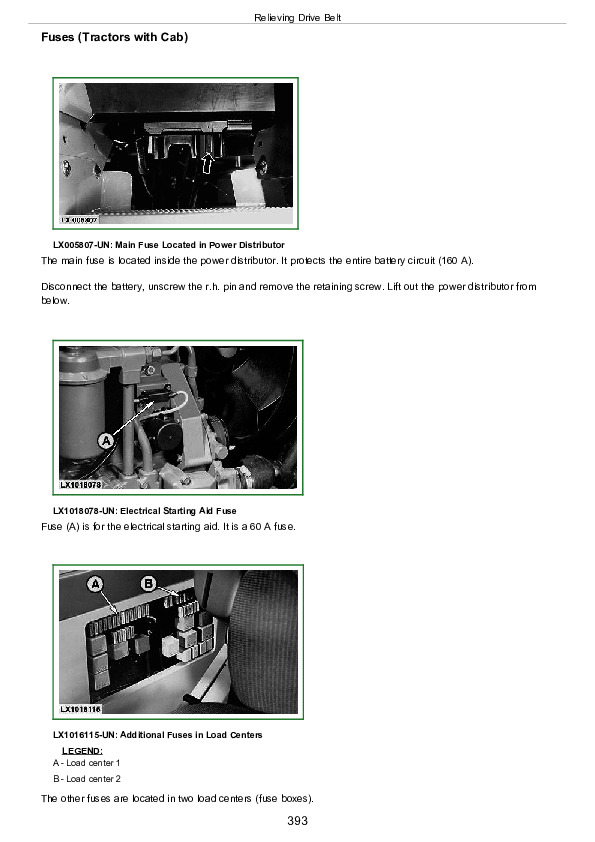
Fuses
Part Designations in Functional Schematic and Wiring Harnesses
Identification of Sections in Functional Schematic
Wiring Harness Identification
Functional Schematic (Complete Tractor)
Wiring Harness for 4-Cylinder Engine (W3; AL150218)
Wiring Harness for 6-Cylinder Engine (W3; AL150219)
Wiring Harness for 6-Cylinder Engine on Tractor Model 6910S (W3; AL153134)
Wiring Harness for Electrical Starting Aid (W27; AL119472)
Wiring Harness for Starting Aid on Tractor Model 6910S (W27; AL153193)
Front Grille Worklight Wiring Harness (W14; AL81307)
TLS Front Wheel Drive Axle Wiring Harness (W36; AL113493)
Front PTO Wiring Harness (W39; AL110126)
Cab Wiring Harness (W4; AL150759)
Cab Wiring Harness with Power Shift Transmission (W4; AL116787)
Cab Wiring Harness on Tractor Model 6910S (W4; AL152074)
Shift Console Wiring Harness with Power Shift Transmission (W45; AL150055)
Air Brake Wiring Harness on 50 km/h Tractors (W54; AL150847)
7-Terminal Socket Wiring Harness (W29; AL114898)
3-Terminal Socket Wiring Harness (W31; AL114895)
Wiring Harness for Electronic Control Units (W34; AL150234)
Wiring Harness for Electronic Control Units on Tractor Model 6910S (W34; AL151361)
Wiring Harness for Stepper Motor Drivers (W35; AL114802)
Turn Signal Lever Wiring Harness (W5; AL77212)
Windshield Wiper Switch Wiring Harness without Intermittent Wipe (W6; AL112539)
Windshield Wiper Switch Wiring Harness with Intermittent Wipe (W6; AL112652)
Cab Roof Wiring Harness (W11; AL150601)
Front Cab Roof Worklight Wiring Harness (W18; AL83139)
Windshield Wiper Wiring Harness without Windshield Switch (W7; AL79007)
Windshield Wiper Wiring Harness with Windshield Switch (W7; AL78113)
Rear Window Wiper Harness (W10; AL116455)
Rear Window Wiper Adapter Harness (W38; AL116548)
Air Conditioning and Fan Wiring Harness (W8; AL110248)
Transmission Wiring Harness on Tractor Models 6010 – 6610 (W13; AL114105)
Transmission Wiring Harness on Tractor Models 6810 – 6910 (W13; AL114902)
Transmission Wiring Harness with Electrical Reverser Control (W20; AL112509)
Transmission Wiring Harness with Power Shift Transmission (W44; RE158398)
Group 10A: Functional Schematics and Wiring Diagrams (SE Tractors)
Fuses
Functional Schematic and Wiring Harness Component Identification
Section Designations on Functional Schematics
Wiring Harness Identification
Functional Schematic (Complete Tractor; SE1)
Wiring Harness for 4-Cylinder Engine (W3; AL150218)
Wiring Harness for 6-Cylinder Engine (W3; AL150219)
Wiring Harness for Electrical Starting Aid (W27; AL119472)
Front PTO Wiring Harness (W39; AL110126)
Cab Wiring Harness (W4; AL116099)
Front PTO Wiring Harness (W43; AL116605)
Cab Roof Wiring Harness (W11; AL110101)
Air Conditioner and Fan Wiring Harness (W8; AL110589)
Transmission Wiring Harness (W13; AL111537)
Group 10B: Functional Schematics and Wiring Diagrams (2-Post ROPS)
Fuses
Functional Schematic and Wiring Harness Component Identification
Section Designations on Functional Schematics
Wiring Harness Identification
Functional Schematic (Complete Tractor; SE1)
Wiring Harness for 4-Cylinder Engine (W3; AL117076)
Wiring Harness for 6-Cylinder Engine (W3; AL117524)
Wiring Harness for Electrical Starting Aid (W27; AL119472)
Front Grille Worklight Wiring Harness (W14; AL81307)
Platform Wiring Harness (W4; AL116785)
7-Pin Receptacle Wiring Harness (W29; AL114898)
3-Pin Receptacle Wiring Harness (W31; AL114895)
Front Part of Transmission Wiring Harness (W32; AL115344)
Rear Part of Transmission Wiring Harness (W33; AL116810)
Group 10C: Functional Schematics and Wiring Diagrams (AutoPowr)
Fuses
Part Designations in Functional Schematic and Wiring Harnesses
Identification of Sections in Functional Schematic
Wiring Harness Identification
Functional Schematic (Complete Tractor)
Wiring Harness for 4-Cylinder Engine (W3; AL153450)
Wiring Harness for 6-Cylinder Engine (W3; AL153134)
Wiring Harness for Starting Aid (W27; AL153193)
Front Corner Worklight Wiring Harness (W14; AL81307)
TLS Front Wheel Drive Axle Wiring Harness (W36; AL113493)
Front PTO Wiring Harness (W39; AL110126)
Cab Wiring Harness (W4; AL152072)
7-Terminal Socket Wiring Harness (W29; AL114898)
3-Terminal Socket Wiring Harness (W31; AL114895)
Wiring Harness for Electronic Control Units (W34; AL151361)
Wiring Harness for Stepper Motor Drivers (W35; AL114802)
Windshield Wiper Switch Wiring Harness without Intermittent Wipe (W6; AL112539)
Windshield Wiper Switch Wiring Harness with Intermittent Wipe (W6; AL112652)
Cab Roof Wiring Harness (W11; AL150601)
Front Cab Roof Worklight Wiring Harness (W18; AL83139)
Windshield Wiper Wiring Harness without Windshield Switch (W7; AL79007)
Windshield Wiper Wiring Harness with Windshield Switch (W7; AL78113)
Rear Window Wiper Harness (W10; AL116455)
Rear Window Wiper Adapter Harness (W38; AL116548)
Air Conditioning and Fan Wiring Harness (W8; AL110248)
Transmission Wiring Harness on Tractor Models 6410 – 6610 (W13; AL153446)
Transmission Wiring Harness on Tractor Models 6810 – 6910 (W13; AL153449)
Group 15: Circuit Testing (6010-6910S with Cab)
Special or Essential Tools
SE1-Starter Motor and Charging Circuit
SE2-Basic Informator
SE3-Horn
SE4-Cigarette Lighter and Operator’s Seat
SE5-Front PTO
SE6-Lights
SE7-Worklights
SE8-Front Loader Plug
SE9-Radio, Digital Clock, Dome and Console Lights
SE10-Fan and Air Conditioner
SE11-Windshield Wiper and Washer
SE12-Rear Window Wiper and Washer
S13-Beacon Light
SE14-3- and 7-Terminal Power Outlet Sockets
SE15-Electronic Hitch Control
SE16A-Basic Control Unit (BCU) (Braking System)
SE16A-Basic Control Unit (BCU) (Braking System, with FWD and Disk Brake)
SE16B-Basic Control Unit (BCU) (Hazard Flasher and Turn Signal Unit)
SE16C-Basic Control Unit (BCU) (Differential Lock)
SE16D-Basic Control Unit (BCU) (Radar)
SE16E-Basic Control Unit (BCU) (Rear PTO without HMS)
SE16F-Basic Control Unit (BCU) (Handbrake Monitor Unit)
SE16G-Basic Control Unit (BCU) (Front Wheel Drive without HMS)
SE16H-Basic Control Unit (BCU) (Power Supply and Rev Counter Sender)
SE16I-Basic Control Unit (BCU) (with Headland Management System)
SE17-Signal Socket
SE18-Performance Monitor
SE19-Electronic Reverser Control
SE20-TLS Front Wheel Drive Axle
SE21A-PowrQuad Plus Shifting
SE21B-Electronically Controlled Independent Control Valves (EICV)
SE21C-EICV Stepper Motor Driver
SE21D-Stepper Motor Driver for PowrQuad Plus Transmission
SE22-BUS Terminator and Terminating Resistor
SE23-Electronic Engine Control
SE 23A-Electronic Engine Control (6910S)
SE27-PowrShift Transmission Control
Group 15A: Sub-System Diagnostics (SE Tractors)
Special or Essential Tools
SE1-Starting Motor and Charging Circuit
SE2-Basic Informator
SE3-Horn
SE4-Operator’s Seat
SE5-Front PTO and Handbrake Monitoring System
SE6-Lighting Circuits
SE7-Work Lights
SE9-Radio, Dome and Console Lights
SE10-Fan and Air Conditioner
SE11-Windshield Wiper and Washer
S13-Beacon Light
SE15-Electronic Hitch Control Unit (HCU)
SE16A-Hazard Warning Flasher and Turn Signal Lights
SE16B-Rear PTO
SE16C-Brake System
SE16D-Differential Lock
SE16E-Front Wheel Drive
Group 15B: Sub-System Diagnostics (2-Post ROPS)
Special or Essential Tools
SE1-Starting Motor and Charging Circuit
SE2-Basic Informator
SE3-Horn
SE6-Lighting Circuits
SE7-Work Lights
SE14-3- and 7-Pin Receptacles and Front Loader Plug
SE15-Electronic Hitch Control Unit (HCU)
SE16A-Hazard Warning Flasher and Turn Signal Lights
SE16B-Rear PTO
SE16C-Brake System
SE16D-Differential Lock
SE16E-Front Wheel Drive
Group 15C: Circuit Testing (AutoPowr Transmission)
Special or Essential Tools
SE1-Starter Motor and Charging Circuit
SE2-Basic Informator
SE3-Horn
SE4-Cigarette Lighter and Operator’s Seat
SE5-Front PTO
SE6-Lights
SE7-Work Lights
SE8-Front Loader Plug
SE9-Radio, Digital Clock, Dome and Console Lights
SE10-Fan and Air Conditioner
SE11-Windshield Wiper and Washer
SE12-Rear Window Wiper and Washer
S13-Beacon Light
SE14-3- and 7-Terminal Power Outlet Sockets
SE15-Electronic Hitch Control
SE16-Basic Control Unit (BCU) (Differential Lock, Radar, Handbrake and Rev Counter Sender)
SE16A-Basic Control Unit (BCU) (with Headland Management System)
SE16B-Basic Control Unit (BCU) (without Headland Management System)
SE16D-Basic Control Unit (BCU) (Hazard Flasher and Turn Signal Unit)
SE17-Signal Socket
SE18-Performance Monitor
SE20-TLS Front Wheel Drive Axle
SE21-Electronically Controlled Independent Control Valves (EICV)
SE21A-EICV Stepper Motor Driver
SE22-BUS Terminator and Terminating Resistor
SE23B-Electronic Engine Control
SE26-Transmission Control Unit
SE27-Transmission Shifting
SE28- Electronic Park Lock
SE30A-Seat and Handbrake Switch
Group 16A: Data BUS Systems
Data BUS Systems
CCD BUS System
CAN BUS System
CCD BUS Diagnostic Schematic
CAN BUS Diagnostic Schematic
CCD BUS Diagnostic Schematic (6910S Tractors)
CAN BUS Diagnostic Schematic (6910S Tractors)
CCD BUS Diagnostic Schematic (Tractors with AutoPowr Transmission)
CAN BUS Diagnostic Schematic (Tractors with AutoPowr Transmission)
DATA BUS Systems
DATA BUS Systems on 6910S Tractors
DATA BUS Systems on Tractors with AutoPowr Transmission
Group 16B: Data BUS Systems –– Diagnosis
Explanation of Data Bus System Tests
Safety Measures
Essential Tools
Malfunctions in the Data BUS System
CCD – Test for SE Tractors and 2-Post ROPS Tractors
CCD – Test for Cab Tractors without RCU and/or SFA
CCD – Test for Cab Tractors equipped with RCU and/or SFA
CCD – Test for Cab Tractors with PowrShift Transmission (PST)
11-BIT CAN BUS Test
29-BIT CAN BUS Test
29-BIT CAN BUS – Test for 6910S Tractors
29-BIT CAN BUS – Test for AutoPowr Transmission
Supply Circuit 072 for Electronic Control Units
Group 20: Adjustments
Explanation of BCU, Basic Informator (BIF) and Performance Monitor (PRF) Testing
Safety Measures
Essential Tools
General Information on Basic Control Unit (BCU)
BCU Addresses
Diagnostic Structure (BCU)
Service Code List (BCU)
Diagnostic Address List (BCU)
Diagnostic Addresses (BCU)
Display Address List (BCU)
Display Addresses (BCU)
Calibration (BCU)
Calibration Address List (BCU)
Calibration Addresses (BCU)
General Information Concerning the Basic Informator (BIF)
Basic Informator (BIF) Addresses
Diagnostic Structure (BIF)
Service Code List (BIF)
Diagnostic Address List (BIF)
Diagnostic Addresses (BIF)
Display Address List (BIF)
Display Addresses (BIF)
Calibration (BIF)
Calibration Address List (BIF)
Calibration Addresses (BIF)
General Information about the Performance Monitor (PRF)
Performance Monitor (PRF) Addresses
Diagnostic Structure (PRF)
Calibration (PRF)
Calibration Address List (PRF)
Calibration Addresses (PRF)
Calibrating the Ground Speed Sensor (Radar)
Setting Wheel Slip Back to Zero
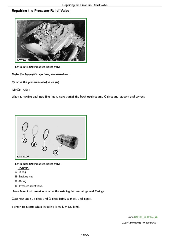
Group 25: Component Testing
Special or Essential Tools
Specifications
SE1-Starting Motor and Charging Circuit
Starter Checks
Alternator Checks
Battery Checks
SE2-Instrument Unit and Lighting
SE3-Horn
SE4-Cigarette Lighter and Operator’s Seat
SE7-Front PTO
SE6-Lighting Circuits
SE7-Work Lights
SE9-Radio, Dome and Shift Console Lights
SE10-Fan and Air Conditioner
SE11 and SE12-Windshield Wiper and Washer
S13-Beacon
SE16A-Basic Control Unit (BCU) (Braking System)
SE16B-Basic Control Unit (BCU) (Hazard Flasher and Turn Signal Unit)
SE16C-Basic Control Unit (BCU) (Differential Lock)
SE16E-Basic Control Unit (BCU) (Rear PTO)
SE16G-Basic Control Unit (BCU) (Front Wheel Drive)
SE16I-Basic Control Unit (BCU) (Headland Management System)
SE19-Electrical Reverser Control
SE20-TLS Front Wheel Drive Axle
SE21A-PowrQuad Plus Shifting
SE21B-Operation of the Electronic Independent Control Valve
Section 245: Electronic Control Units
Group 05: Operation and General Information on Diagnostics
General Explanation of Testing Procedures for Electronic Control Units
Safety Measures
Essential Tools
Diagnostics with Digital Display
Diagnosis with the Performance Monitor
Abbreviations Used in Display
Diagnostic Structure
Entering Program Mode
Calling up and Deleting Service Codes
Electronic Control Units – Identification Addresses
Group BCU: BCU References
Supply Circuit 973 (BCU Functions; Not for tractors with AutoPowr Transmission)
Rear PTO Speed Sender Circuit Test
Handbrake Switch Circuit Test
Differential Lock Switch Circuit Test
MFWD Switch Circuit Test
HMS Switch Circuit Test
Rear PTO Switch Circuit Test
Rear PTO-Remote Control Circuit Test
Turn Signal Switch Test
Hazard Flasher Switch Circuit Test
BCU and Tractor System-Voltage-Circuit Test
Group BIF: BIF References
Fuel Level (Gauge) Sensor Test
Coolant Temperature Sensor Circuit Test
Transmission Oil Temperature Sensor Circuit Test
Engine Oil Pressure Sender Test
Engine Speed Signal Circuit Test
Transmission Oil Pressure Switch Circuit Test
Air Filter Switch Circuit Test
Oil Filter Restriction Switch Circuit Test
Oil Filter Restriction Switch Circuit Test for AutoPowr Transmission
BIF Supply Voltage and Tractor System Voltage Test
Alternator Circuit Test
Flasher Cycle Input Signal Circuit Test
Group ECU: ECU (Level 1) References
Foot Throttle Potentiometer Supply Circuit Test
Foot Throttle Potentiometer Output Circuit Test
Cruise Control Potentiometer Supply Circuit Test
Cruise Control Potentiometer Output Circuit Test
Coolant Temperature Sensor Circuit Test
Engine Speed Sensor Circuit Test
Fuel Injection Pump Solenoid Circuit Test
Starting Circuit Test
Group HCU: HCU References
HCU Beep Mode Test (HCU 02)
Quick Raise/Lower Rocker Switch Circuit Test
(L.H.) Draft Sensor Output Circuit Test
(R.H.) Draft Sensor Output Circuit Test
Load/Depth Control Potentiometer Output Circuit Test
Hitch Height Control Potentiometer Output Circuit Test
Position Sensor Potentiometer Output Circuit Test
Raise-Limit Control Potentiometer Output Circuit Test
Rate-of-Drop Control Potentiometer Output Circuit Test
Remote Control Switch Circuit Test
Potentiometer Supply Voltage Circuit Test
Draft Sensor Supply Voltage Circuit Test
Stepper Motor Circuit Test
HCU Power Supply – Circuit Test
Group PCU: PCU References
PCU Beep Mode Test (PCU 02)
Manifold Pressure (MAP) Sensor Circuit Test
Clutch Engaged Switch Circuit Test
Clutch Disengaged Switch Circuit Test
Forward Switch Circuit Test
Reverse Switch Circuit Test
Not-Neutral Switch Circuit Test
Transmission Enable Signal Test
Group PEC: PEC References
PEC Beep Mode Test (PEC 02 and PEC 03)
Upshift Circuit Test
Downshift Circuit Test
Power/ECO Mode Switch Circuit Test
AutoQuad Switch Circuit Test
Stepper Motor Driver (SMD0) Power Supply and Identification Circuit Test
Stepper Motor (M15) and Stepper Motor Driver (SMD0) Circuit Test
E-ICV –– Multi-Function Lever Axis 1 – Test (Forward and Rearward Lever Position)
E-ICV –– Multi-Function Lever Axis 2 – Test (Left and Right Lever Position)
E-ICV –– Multi-Function Lever Axis 3 – Test (Rocker Switch – Upper and Lower Position)
E-ICV –– Multi-Function Lever Potentiometer Supply Circuit Test
E-ICV –– Transport Lock Switch Circuit Test
E-ICV –– Interlock Switch Circuit Test
E-ICV –– Stepper Motor Driver (SMD1, 2 and 3) Power Supply and Identification Circuit Test
E-ICV No.1 –– Stepper Motor (M12) and Stepper Motor Driver (SMD1) Circuit Test
E-ICV No.2 –– Stepper Motor (M13) and Stepper Motor Driver (SMD2) Circuit Test
E-ICV No.3 –– Stepper Motor (M14) and Stepper Motor Driver (SMD3) Circuit Test
Group PLC: PLC References
Preliminary Test for PLC Circuit
Circuit Test for Park Lock Controller (Signals from Reverse Drive Lever)
Circuit Test, Output Speed Sender (B84) on Transmissions with PLC
Circuit Test for Park Lock Solenoid Valve (Y15-2)
Circuit Test for Acoustic Alarm (K202)
Circuit Test for Park Lock Pressure Sensor (B90)
Group RCU: RCU References
Recall Codes Procedure for RCU
RCU Beep Mode Test (RCU 02)
Test Procedure for Diagnostic Address RCU 03
Test Procedure for Diagnostic Address RCU 04
Test Procedure for Diagnostic Address RCU 05
Test Procedure for Diagnostic Address RCU 06
Test Procedure for Diagnostic Address RCU 07
Check Forward Solenoid Circuit
Check Reverse Solenoid Circuit
Group SFA: SFA References
SFA Beep Mode Test (SFA 02)
Solenoid Valve 1 (Y10) Circuit Test
Solenoid Valve 2 (Y11) Circuit Test
Position Sensor (B53) Supply Voltage Circuit Test
Position Sensor (B53) Output Circuit Test
Magnet Sending Unit (B35) Circuit Test
Hall Sending Unit (B09) Circuit Test
Test Procedure for SFA Hydraulic System
Test Procedure for Accumulator Precharge System
Group TCU: TCU References
Adapter Test Harness for AutoPowr Transmission––KJD10265
Preliminary Test for TCU Circuit
Testing the Connectors on the AutoPowr Controllers
Circuit Testing for the Neutral Signal Control Circuit
Circuit Testing for the Control Circuit of the Internal Transmission Power Supply (VPS)
Circuit Test for Oil Temperature Sending Unit
Circuit Test for Transmission Oil Filter Sender S73
Circuit Test for Transmission Oil Pressure Sender S74
Circuit Test for Filter By-pass Valve (Cold-Weather Starting), Sending Unit (B87)
Circuit Test for Transmission Input Speed Sending Unit (B61)
Circuit Test for Transmission Output Speed Sending Unit (B63)
Circuit Test for Hydrostatic Speed Sending Unit (B62)
Circuit Test for Park Lock Solenoid Valve (Y15-1)
C1 Solenoid Valve Circuit Test
C2 Solenoid Valve Circuit Test
C3 Solenoid Valve Circuit Test
C4 Solenoid Valve Circuit Test
BG Solenoid Valve Circuit Test
Circuit Test for Proportional Solenoid Y1
Circuit Test for Proportional Solenoid Y2
Circuit Test for CF Forward Clutch
Circuit Test for CR Reverse Clutch
Test Chart for AutoPowr Transmission
Group UIC: UIC References
Preliminary Check on UIC Circuit
Circuit Test for Reverse Drive Lever (S80)
Circuit Test for Cruise Control Potentiometer (A19)
Circuit Test for AutoPowr Selector (B83)
Circuit Test for Speed Wheel at Speed Control Lever (S108)
Circuit Test for Speed Ranges 1 and 2 at Speed Control Lever (S108 and B67)
Circuit Test for Hand Throttle Potentiometer (B78)
Circuit Test for Foot Throttle Potentiometer (B79)
Circuit Test for Brake Pedal Sensors (B88)
Circuit Test for Clutch Pedal Potentiometer (B65)
Circuit Test for FWD Axle Speed Sending Unit (B89)
Circuit Test for Air Brake Solenoid Valve (Y31)
Circuit Test for Seat Switch (S40)
Circuit Test for Come-Home Function (K201)
Section 250: SyncroPlus Transmission
Group 05: Operational Checkout
Checking If Perma Clutch II Separates Properly
Checking Perma Clutch II for Slippage
Checking the Slip Phase of Perma Clutch II
Checking the Transmission
Checking the Neutral Start Switch
Group 10: Troubleshooting
Essential Tools
Specifications
Safety Precautions
Explanation of System Diagnosis (Troubleshooting)
Hydraulic Oil Warm-Up
Connecting JT07115 Hydraulic Test Kit
Connecting the Sensocontrol© Testing Equipment
Layout of Test Ports and Sending Units
Preliminary Checks
Checking Gear and Range Engagement
Checking Clutch Operation
Transmission Oil Filter Check
Checking System (Engagement) Pressure
Adjusting System (Engagement) Pressure
Check Components Dependent on System (Engagement) Pressure
Checking the Filter Relief Valve
Testing the Engagement Override Valve and Clutch Pedal Valve
Checking the Modulation of the Clutch Pedal Valve
Checking Lubricating Oil Pressure
Checking the Clutch Cooling System
Checking the Flow Rate
Checking the Cooler Relief Valve
Group 15: Tests and Adjustments
Essential Tools
Specifications
Shift Linkage Test
Range Transmission Linkage Test
Adjusting Range Box Shifting
Gear Transmission Linkage Test
Adjusting Shift Linkage at Gear Transmission
Adjusting the Neutral Start Switch
Checking the Neutral Start Switch
Adjusting the Shift Linkage and Parking Lock
Clutch Pedal Adjustment
Group 20: SyncroPlus Transmission Operation
Layout of 12-Speed Transmission
Layout of 12-Speed Transmission with Creeper
Lubrication System
Shift Operation
Synchronization
Transmission Circuit Hydraulic Schematic
Transmission Circuit – Theory of Operation
Group 20A: Perma Clutch II
Exploded View of Perma Clutch II
Clutch Design
Power Flow, Clutch Pedal Depressed
Power Flow, Clutch Pedal Not Depressed
Theory of Operation – Transmission Oil Pump
Hydraulic Schematic of Perma Clutch II
Description of Valves and Other Hydraulic Components
Theory of Operation – Pressure Regulating and Filter Relief Valves
Theory of Operation – Clutch Pedal and Engagement Override Valves
Theory of Operation – Cooling
Group 20B: Gear Transmission
Gear Transmission Design
Power Flow in 1st Gear
Power Flow in 2nd Gear
Power Flow in 3rd Gear
Power Flow in Reverse Gear
Neutral Start Switch
Group 20C: Creeper Transmission
Layout of Creeper Transmission
Power Flow With Creeper Disengaged
Power Flow With Creeper Engaged
Group 20D: Range Transmission
Range Transmission
Layout
Power Flow in Range A
Power Flow in Range B
Power Flow in Range C
Power Flow in Range D
Parking Lock
Section 251: Power Reverser Transmission
Group 05: Operational Checkout
Before You Start
Checking the Neutral Start Switch
Neutral-to-Gear Modulation Check
Reverser Control Modulation Check
Gear Engagement Check
Range Engagement Check
Clutch Modulation Check
Transmission Creep Check
Clutch Engagement Check
Group 10: Troubleshooting
Essential Tools
Specifications
Safety Precautions
Explanation of Troubleshooting
Hydraulic Oil Warm-Up
Connecting the JT07115 Hydraulic Test Kit
Connecting the Sensocontrol© Testing Equipment
Layout of Test Ports and Sending Units
Preliminary Checks
Checking Gear and Range Engagement
Checking Forward/Reverse Modulation
Transmission Oil Filter Check
Checking System (Engagement) Pressure
Adjusting System (Engagement) Pressure
Checking Components Dependent on System (Engagement) Pressure
Checking the Filter Relief Valve
Checking the Engagement Override Valve and Clutch Pedal Valve
Checking the Disk Clutch and Disk Brake
Checking Lubricating Oil Pressure
Checking the Clutch Cooling System
Checking the Flow Rate
Checking the Cooler Relief Valve
Group 15: Test and Adjustments
Special Tool (Dealer-Manufactured)
Shift Linkage Test
Range Transmission Linkage Test
Adjusting Range Transmission Linkage
Gear Transmission Linkage Test
Adjusting Shift Linkage at Gear Transmission
Adjusting the Reverser Control Linkage
Adjusting the Shift Linkage and Parking Lock
Adjusting the Reverse Drive Lever
Clutch Pedal Adjustment
Group 20: Power Reverser Operation
Design of Power Reverser
Description of Transmission Oil Circuit
Group 20A: Power Reverser Module
Components
Design and Powerflow
Power Reverser Module – Sectional View
Theory of Operation – Transmission Oil Pump
Valves and Other Hydraulic Components
Power Reverser – Hydraulic Circuit Diagram
Description of Valves and Other Hydraulic Components
Theory of Operation – Pressure Regulating and Filter Relief Valves
Theory of Operation – Forward/Reverse Modulation
Theory of Operation – Clutch Pedal Valve
Theory of Operation – Engagement Override Valve
Theory of Operation – Cooling
Group 20B: Gear Transmission
Illustration of Gear Transmission
Design and Powerflow
Section 252: Power Shift Transmission
Group 05: Operational Checkout
Before You Start
Group 10: Troubleshooting
Special Tools
Avoid High-Pressure Fluids
Adjust for Correct Pressure and Temperature References
Observe Safety Precautions
PCU Description
Gear Number Display
Element Engagement Chart
Come-Home Feature and Operation
General Information on Diagnostics
Notes on the Diagnostic Program
Service Code List (PCU)
Diagnostic Address List (PCU)
Address 03, Checking the Gear Encoder
Address 20, Troubleshooting the Driver/Element Circuit
Calibration Address List (PCU)
Calibrating the Power Shift Transmission
Calibration Fault
Error Messages
Troubleshooting System Tests
Additional Troubleshooting Test Procedures
Group 15: Adjustments
Adjusting the Parking Lock
Group 20: Theory of Operation
Layout of PowerShift Transmission
PST Transmission (Components)
Planetary Operation
Element Engagement Chart
Hydraulic Control of Transmission
Analog Shift Valve (FEMA Valve)
Analog Shift Valve (Clutch Disengaged)
Analog Shift Valve (Clutch Engaged)
Analog Valve Commands for On-Coming Clutch
Reduction Gear Box
PST Transmission (Components)
Section 253: AutoPowr Transmission
Group 10A: Diagnosis – UIC
General Information on Diagnostics
UIC – Service Code List
UIC – Diagnostic Addresses
UIC – Display Addresses
UIC – Calibration and Input Addresses
Group 10B: Diagnosis – TCU
General Information on Diagnostics
TCU – Service Code List
TCU – Diagnostic Addresses
TCU – Display Addresses
TCU – Calibration and Input Addresses
TCU – Output Test Mode Chart
Group 10C: Diagnosis – PLC
General Information on Diagnostics
PLC – Service Code List
PLC – Diagnostic Addresses
PLC – Display Addresses
PLC – Calibration and Input Addresses
Group 15: Tests and Adjustments
Special Tools
Specifications
Test Ports for Hydraulic Tests (6410 and 6610)
Test Ports for Hydraulic Tests (6810 and 6910)
Checking System Pressure
Checking Reduced System Pressure (Pressure for Other Consumers)
Checking Oil Cooler Pressure
Checking Lube Oil Pressure
Checking Pressure at the C1 Clutch
Checking Pressure at the C2 Clutch
Checking Pressure at the C3 Clutch
Checking Pressure at the C4 Clutch
Checking Pressure at the BG Disk Brake
Checking Pressure at the Forward Clutch (CF)
Checking Pressure at the Reverse Clutch (CR)
Group 20: Operation
Operation
Layout of Transmission Components
Sectional View of Transmission
Transmission Peripherals
Components for Transmission Control
Transmission Control
Description of Transmission Oil Circuit
Description of System Pressure Control Block
Description of Clutch Control Block
Operation of Hydrostatic Unit
Transmission Layout
Element Engagement Chart
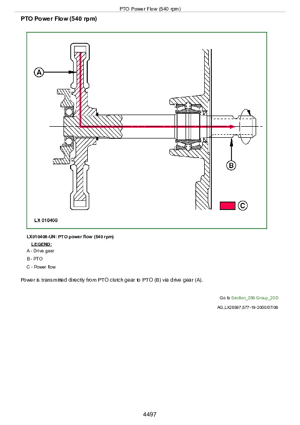
Power Flows
Oil Flows
Operation of Park Lock
Shift Controls
Section 255: PowrQuad, PowrQuad Plus and AutoQuad II Transmissions
Group 05: Operational Checkout
Before You Start
Group 10A: POWRQUADPOWRQUAD is a trademark of Deere & Company. Transmission Check
Use Step-by-Step Hydraulic Diagnostic Charts
Special or Essential Tools
Connecting the SensoControl Testing Equipment
Service Equipment and Tools
Other Material
Observe Safety Precautions
Legal Requirements
General Information on Diagnostics
Notes on the Diagnostic Program
Service Code List (RCU)
Diagnostic Address List (RCU)
Calibration Address List (RCU)
Calibrating the RCUReverser Control Unit (electronic control unit for electrical reverser control)
Adjust for Correct Pressure and Temperature References
Shortened Diagnostic Procedure
Test-Driving the Tractor
Troubleshooting System Test
Major System Checks
Additional Troubleshooting Test Procedures
Group 10B: Troubleshooting on PowrQuad Plus and AutoQuad II
Special or Essential Tools
General Information on Diagnostics
Notes on the Diagnostic Program
Service Code List (PEC) – Transmission
Diagnostic Address List (PEC) – Transmission
List of Calibratable Addresses (PEC) – Transmission
Group 15: Tests and Adjustments
Reverser Control Linkage Adjustment (6010 to 6610 Tractors)
Reverser Control Linkage Adjustment (6810 and 6910 Tractors)
Adjusting Shifter and Parking Lock – Reverser Control on Shift Console
Adjusting the Shift Linkage and Parking Lock – Reverser Control on Steering Column
Adjusting the Shift Linkage and Parking Lock
Clutch Pedal Adjustment
Transmission System Pressure Check
Group 20A: PowrQuad Transmission Operation
PowrQuad Transmission Layout (6810 and 6910)
PowrQuad Transmission Layout (6110 to 6610)
PowrQuad Module
Planetary Operation
Air Pump
Transmission Oil Pump
Clutch Oil Manifold
Reverse Brake Housing
Forward/Reverse Controls
Hydraulic Schematic – Mechanical Reverser Control
Hydraulic Schematic – Electrical Reverser Control
Filter Bypass Valve
Pressure Regulating Valve
Forward-Reverse Modulation
EOV Circuit (With Mechanical Reverser Control)
Theory of Operation – Electrical Reverser Control
Positions of the Reverse Drive Lever
Parking Lock Switch
Reverse Lockout Switch (if equipped)
Valve Housing on PowrQuad Module
Relays
Reverser Control Unit (RCU)
Detail of Hydraulic Circuit Diagram (Simplified)
Speed Control Circuit
Speed Modulation
Clutch Cooling Components
Oil Cooler
Clutch Cooling Valve
Forward/Reverse Cooling Control Valve
Oil Cooler and Lube Circuits
Module Lube
Module Lube Flow Paths
Test Ports and Sending Units – With Mechanical Reverser Control
Test Ports and Sending Units – With Electrical Reverser Control
Group 20B: PowrQuad Plus and AutoQuad II Transmission Operation
PowrQuad Module
PowrQuad, PowrQuad Plus and AutoQuadII Transmissions
Comparison of Transmission Versions
PowrQuad Plus, AutoQuad and AutoQuad II Transmission Components
Description of PEC
Electric Shifting
Automatic Speed Matching
Automatic Shifting
Group 20C: Creeper Transmission
Creeper Transmission Sectional View (6810 and 6910 Tractors)
Creeper Transmission Operation (6110-6610 Tractors)
Power Flow with Creeper Disengaged
Power Flow with Creeper Engaged
Group 20D: Range Transmission
Design (16-Speed Transmission)
Design (20-Speed Transmission)
Design (24-Speed Transmission)
Power Flow in Range A (16-Speed Transmission)
Power Flow in Range B (16-Speed Transmission)
Power Flow in Range C (16-Speed Transmission)
Power Flow in Range D (16-Speed Transmission)
Power Flow in Range A (20- and 24-Speed Transmissions)
Power Flow in Range E (20- and 24-Speed Transmissions)
Power Flow in Range F (24-Speed Transmission)
Parking Lock
Sectional View of Range Transmission (6810 and 6910 Tractors)
Section 256: Drive Systems
Group 05: Operational Checkout
Checking the Differential Lock
Checking the Front and Rear PTOs
Checking Front-Wheel Drive
Group 10: Troubleshooting
Differential
Front PTO
Rear PTO
Front-Wheel Drive
Hydraulic Pump Drive
Final Drives
Group 15: Tests
Safety Measures
Special or Essential Tools
Connecting the SensoControl Testing Equipment
Specifications
Testing Front Wheel Drive Clutch System Pressure
Testing Hydraulic Differential Lock System Pressure
Testing the Rear PTO
Front PTO Check
Group 20A: Front-Wheel Drive Clutch
Design (6010-6610 Tractors)
Oil and Power Flows With Front-Wheel Drive Engaged
Oil and Power Flows with Front Wheel Drive Disengaged
Design (6810 and 6910 Tractors)
Oil and Power Flows With Front-Wheel Drive Engaged
Oil and Power Flows with Front Wheel Drive Disengaged
Group 20B: Differential
Design (6010-6610 Tractors)
Design (6810 and 6910)
Power Flow when Moving Straight Ahead
Power Flow when Cornering
Oil Flow With Differential Lock Engaged
Oil Flow With Differential Lock Disengaged
Group 20C: Final Drives
Operation and Layout
Group 20D: Rear PTO Options
Description of Rear PTO Options
PTO Modulating Valve and Solenoid Valve
PTO Clutch and PTO Brake
Lube Cut-Off Valve
PTO Power Flow (540 rpm)
PTO Power Flow (540/1000 rpm, Reversible)
Power Flow for Shiftable 540/1000 rpm and 540/540E/1000 rpm PTO
Group 20E: Front PTO
Front PTO Operation
Independent Hydraulic Circuit
Oil Cooler
Modulating Valve and Solenoid
Hydraulic Pump
Section 260: Steering and Brakes
Group 05: Operational Checkout
Checking the Steering
Checking the Brakes
Checking the Handbrake
Air Brake System Check (Filling Pressure and Leak Test)
Group 10: Troubleshooting
Hydrostatic Steering
Hydraulic Brakes (Without Power Assist)
Handbrake
Hydraulic Trailer Brake
Air Brake System
Group 15: Tests and Adjustments
Special Tools
Connecting the SensoControl Testing Equipment
Specifications
Testing Leaf Springs of Steering Valve
Checking Steering System for External Leakage
Checking the Steering System for Internal Leakage
Steering Valve Leak Check
Steering Valve Hydraulic Connections
Checking and Adjusting the Double-Acting Shock Valves
Checking Brake System
Checking Brakes for Air in the System
Brake External Leak Check
Brake Valve Internal Leak Check
Bleeding the Brakes (Brake Valve, Non-Power Brakes)
Checking Brake Plunger Travel
Checking Control Valve Opening Pressure – Preliminary Work
Checking Opening Pressure of Control Valve
Adjusting the Brake Pedals
Adjusting the Brake Switches
Checking Rear Brakes
Bleeding the Brakes (Brake Valve, Power-Fill Brakes and MFWD and Disk Brake)
Adjusting the Brake Light Switches
Checking the Handbrake
Handbrake Adjustment
Checking the Trailer Brake Valve
Adjusting the Trailer Brake Valve
Checking Air Brake System (Visual Checks)
Checking the System for Leaks
Checking the “Supply” Coupling End
Checking Dual-Line Brakes
Checking Single-Line Brakes
Adjusting the Handbrake (With Air Brake System)
Group 20A: Hydrostatic Steering
Description of Steering Valve
Operation of Metering Unit
Oil Flow In Steering System
Oil Flow – Neutral Position
Oil Flow – Emergency Steering
Miscellaneous Steering Units
Group 20B: Hydraulic Brakes
Brake Valve (Non-Power Brakes)
Power Brake Valve
Brake Valve (with MFWD and Disk Brake)
Rear Wheel Brakes
Group 20C: Handbrake
Description
Group 20D: Hydraulic Trailer Brake
Ascertaining the Pressure Ratio
Oil Flow in Trailer Brake Valve
Check Valve
Group 20E: Air Brake System
Description of Air Brake System
Compressor
Pressure Regulating Valve
Compressed Air Tank
Trailer Control Valve
Coupling End
Description of Air Brake System (with MFWD and Disk Brake)
Pressure Flow in Air Brake System (with MFWD and Disk Brake)
Compressor
Pressure Regulating Valve
Compressed Air Tank
Preload Valve
Trailer Control Valve
Coupling End
Section 270: Hydraulic System
Group 05: Operational Checkout
Operational Checkout Notes
Safety Precautions
Operational Checks
SCV Check
Rockshaft – Operational Checkout
Checking the Rockshaft Valve and the Stepper Motor of External Control Switch
Group 10: PFC Hydraulic System Troubleshooting
Troubleshooting Notes
Safety Precautions
Special Tools
Connecting Test Equipment – Test Ports
Connecting the SensoControl Testing Equipment
Heating Up Hydraulic Oil
Test Specifications
Test Sequence
PFC Hydraulic System Troubleshooting
Information on System Diagnosis
PFC Hydraulic System Test Result Log
Group 11: PC Hydraulic System Troubleshooting
Troubleshooting Notes, PC Hydraulic System
Safety Precautions
Special Tools
Connecting Test Equipment – Test Ports
Connecting the SensoControl Testing Equipment
Heating Up Hydraulic Oil
Test Specifications
Test Sequence
PC Hydraulic System Troubleshooting
Information on System Diagnosis
PC Hydraulic System Test Result Log
Group 15: Tests and Adjustments
Explanation of the Hydraulic Tests
Safety Measures
Special Tools
Connecting Test Equipment
Connecting the SensoControl Testing Equipment
Heating up the Hydraulic Oil
Lube Oil Pressure of Charge Pump
Testing and Adjusting the Hydraulic Pump System Pressure (PFC Hydraulic System)
Adjusting the Hydraulic Pump Load-Sensing Valve
Checking Load Sense Pressure (Pilot Pressure)
Checking the Load-Sensing Valve
Differential Pressure (Dynamic) (PFC Hydraulic System Only)
Check for Leaks at Valve Spools (PFC Hydraulic System Only)
Causes of Internal Leaks
Diagnosing Faults at the Selective Control Valves
Diagnosing Faults at Independent Control Valves
Checking Pressure Relief Valve of Rockshaft
Adjusting the Power Beyond Application Valve
Charge Oil Pump – Volume
Hydraulic Pump – Volume
General Information on Diagnostics
Control Unit Testing and Adjustment
Testing, Calibrating and Adjusting the Hitch Control Unit (HCU)
Rockshaft Controls
Test Sequence – Rockshaft
Service Code List (HCU) – Rockshaft
Diagnostic Address List (HCU) – Rockshaft
Calibration (HCU) – Rockshaft
Quick Reference, Calibration (HCU) – Rockshaft
Enabling Sway Dampening on HCU (Rockshaft)
Additional Checks
Checking for Leaks at the Rockshaft Valve
Checking the Stepper Motor and Rockshaft Valve
Centering the Stepper Motor
Depth to Which Pressure and Discharge Valves Are Screwed In
Checking the Position Sensor – 6010 to 6910S
Checking and Adjusting Draft Sensors – 6010 to 6610
Checking and Adjusting Draft Sensors – 6810 to 6910S
Checking, Calibrating and Adjusting the Electrical Control for Independent Control Valves (PEC)
Multi-Function Lever – Electrical
Test Procedure – Independent Control Valves
PEC Service Code List – Independent Control Valves
Diagnostic Address List (PEC) – Independent Control Valves
Calibration (PEC) – Independent Control Valves
Quick Reference, Calibration (PEC) – Independent Control Valves
Enabling Function 2 or 3 (PEC) – Independent Control Valves
Checking the Stepper Motor and Stepper Motor Driver
Group 20: PFC Hydraulic System
Hydraulic Symbols (ISO 1219)
Description of Hydraulics in PFC Hydraulic System
PFC Hydraulic System Operation
PFC Hydraulic System – Symbolic View
PFC Hydraulic System – Schematic View
PFC Hydraulic System – Three-Dimensional View
Group 20A: Charge Oil Pump
Charge Pump – Description and Theory of Operation
Group 20B: Hydraulic Pumps
Description of Hydraulic Pump
Layout of Oil Lines
Hydraulic Pump – Theory of Operation
Operating Modes
Group 20C: Valves, Oil Cooler and Filter
Hydraulic Oil Filter With Filter Relief Valve
Oil Cooler
Primary Filter
Shuttle Valve Description, PFC Hydraulic System
Shuttle Valve Operation
Main Valve Block with Priority Valve
Priority Valve Operation
Power Beyond Valve
Group 20D: Rockshaft
Rockshaft Description
Rockshaft Operation
Rockshaft Valve – Theory of Operation
Position Sensor
Draft Sensor
Control Console
Hitch Control Unit (HCU)
Direct Control of Rockshaft
Group 20E: Selective Control Valves and Couplers
Selective Control Valves
100 Series Selective Control Valve – Neutral Position
100 Series Selective Control Valve – Extend Position
100 Series Selective Control Valve – Retract Position
100 Series Selective Control Valve – Float Position
200 Series Selective Control Valve – Neutral Position
200 Series Selective Control Valve – Extend Position
200 Series Selective Control Valve – Retract Position
200 Series Selective Control Valve – Float Position
300 Series Selective Control Valve – Neutral Position
300 Series Selective Control Valve – Extend Position
300 Series Selective Control Valve – Retract Position
300 Series Selective Control Valve – Float Position
Couplers
Endplates on SCV Units – Summary
Group 20F: Independent Control Valve (ICV)
Description
Independent Control Valve (Mechanically Actuated) – Sectional View
Independent Control Valve (Electrically Actuated) – Sectional View
Oil Flow Through the Independent Control Valve
Special Endplate on R.h. Side
Group 21: PC Hydraulic System and Components
Description of Hydraulics in PC Hydraulic System
PC Hydraulic System Operation
Hydraulic System – Symbolic View
Hydraulic System – Schematic View
Hydraulic System – Three-Dimensional View
Description of Hydraulic Pump
Layout of Oil Lines
Hydraulic Pump – Theory of Operation
Hydraulic Oil Filter With Filter Relief Valve
Oil Cooler
Filter Screen
Lube Priority Valve
Shuttle Valves on PC Hydraulic System – Theory of Operation and Layout
Main Block with Inlet Priority Valve and By-Pass Valve
Inlet Priority Valve and By-Pass Valve – Theory of Operation
Rockshaft and Hitch Control
Selective Control Valves of Series 101, 201 and 301
Power Beyond Valve
Section 280: Miscellaneous
Group 05: TLS Front Axle Operational Checkout
Operational Checkout Notes
Safety Measures
Operational Checkout
Monitoring and Warning Device Notes
Monitoring and Warning Devices
Group 10: TLS Front Axle Troubleshooting
Special Tools
General Information on Diagnostics
Safety Measures
System Diagnosis (Troubleshooting)
Troubleshooting
Notes on the Diagnostic Program
Explanation, System Start – System Fault
Explanation of Monitoring and Warning Devices
Test Sequence-Troubleshooting
Explanation of Diagnostics Address 01
Explanation of Diagnostics Address 02
Service Code List (SFA)
Diagnostic Address List (SFA)
Calibrating the FWD axle with TLS
Group 15: TLS Front Axle Tests and Adjustments
Explanation of Tests and Adjustments
Safety Measures
Special or Essential Tools
Additional Tools Required
Notes on Nitrogen Precharge
Relieving Hydraulic System Pressure
Installing/Removing the FKM10474 Fill and Check Device
Checking Nitrogen Precharge
Reducing the Nitrogen Precharge
Increasing the Nitrogen Precharge
Nitrogen Precharge
Accumulator Specifications
Bleeding the Hydraulic System
Group 20: TLS Front Axle Operation
6110-6410 Tractor Suspension
6510-6910 Tractor Suspension
6110-6910 Tractor Components
Operation
Description-Level Control
Hydraulic Circuit Schematic-Suspension Function
Hydraulic Circuit Schematic-Level Control (UP)
Hydraulic Circuit Schematic-Level Control (DOWN)
Electronic Control Unit (SFA)
Position Sensor
Section 290: Operators Cab
Group 05: Operational Checkout
Test Sequence
Operational Checks on Air Conditioning, Heater and Operator’s Seat
Group 10A: Air Conditioner Troubleshooting
Safety At Work
Handling Refrigerant
Safety Equipment
In an Emergency
Storage of Refrigerant Containers
R134A Refrigerant
Important Note
Special or Essential Tools
Special Tools
Specifications
Troubleshooting
Explanation of Checks
Pressure Deviations
Group 10B: Ventilation and Heater Troubleshooting
Ventilation and Heater Troubleshooting
Group 10C: Operator’s Seat Troubleshooting
Diagnosis, MSG95 Operator’s Seat
Group 20A: Air Conditioner Operation
Principle of Heat Exchange
R134A Refrigerant
Refrigerant Circuit Diagram (6110 to 6910 Tractors)
Refrigerant Circuit Diagram (SE Tractors)
Description of How Refrigerant Circuit Functions
Compressor
Condenser
Receiver-Drier
Expansion Valve
Thermostat Switch
Evaporator
High and Low Pressure Switches
Temperature Control and Compressor Switch
Knobs for Heating and Cooling
Group 20B: Ventilation and Heating Operation
Heating and Ventilation on 6110-6910 Tractors
Heating and Ventilation on SE Tractors
Section 299: Special Tools (Dealer-Fabricated)
Group 05: Special Tools (Dealer-Fabricated)
Holding Tool
Adjusting Tool
DFRW2-Needle Valve Test Hose Assembly
DFRW85-Reverse Brake Test Plate
DFLX10 and DFLX11 -Tap-Out Harnesses
DFLX12 – 11-BIT- and 29-BIT- CAN BUS Special Tool
DFLX13 – PCU Calibration Connection (B4 Element)
DFLX14 –– Solenoid Test Harness
John Deere Tractors 6010, SE6010, 6110, SE6110, 6210, 6310, 6410, SE6410, 6510, SE6510, 6610, SE6610, 6810, 6910, 6910S Diagnosis & Tests Technical Technical Manual (TM4552)
INSTANT DOWNLOAD