Posted on

John Deere 7210, 7410, and 7510 Tractors Operator’s Manual (OMAR189655)


INSTANT DOWNLOAD


Complete service Operator’s Manual for John Deere 7210, 7410, and 7510 Tractors, with all the technical information to maintain and operate.

OMAR189655 – John Deere 7210, 7410, and 7510 Tractors (050001- ) Operator’s Manual.pdf
omar189658 French – Tracteurs 7210, 7410 et 7510 (50001 – )
omar162572 English – 7210 and 7410 Tractors ( -050000) Operator’s Manual
omar168939 English – 7210, 7410, and 7510 Tractors ( -050000) Operator’s Manual
omar168940 French – Tracteurs 7210, 7410 et 7510
omar189659 Spanish – 7210, 7410 y 7510 (050001 – ) Operator’s Manual
omar189660 English – 7210, 7410, and 7510 Tractors (050001- ) Operator’s Manual
omn300650 English – 7260 Cotton Picker(Export Edition)(S.N. 000101-) Operator’s Manual

PRODUCT DETAILS:
Total Pages: 552 pages
File Format: PDF (Internal Links, Bookmarked, Table of Contents, Searchable, Printable, high quality)
Language: English French

TABLE OF CONTENTS
Section 05: Safety….19
  Recognize Safety Information….21
  Understand Signal Words….22
  Follow Safety Instructions….23
  Prevent Machine Runaway….24
  Use Seat Belt Properly….25
  Use Foldable ROPS and Seat Belt Properly….26
  Operating the Tractor Safely….27
  Stopping and Parking Tractor….29
  Keep Riders Off Machine….30
  Handle Fuel Safely-Avoid Fires….31
  Prepare for Emergencies….32
  Handle Starting Fluid Safely….33
  Wear Protective Clothing….34
  Protect Against Noise….35
  Handle Chemical Products Safely….36
  Avoid Contact with Pesticides….140
  Stay Clear of Rotating Drivelines….38
  Use Safety Lights and Devices….39
  Use a Safety Chain….40
  Transport Towed Equipment at Safe Speeds….41
  Use Caution on Hillsides….43
  Freeing a Mired Machine….349
  Transport Tractor Safely….45
  Service Cooling System Safely….46
  Practice Safe Maintenance….47
  Support Machine Properly….48
  Remove Paint Before Welding or Heating….49
  Avoid Heating Near Pressurized Fluid Lines….50
  Avoid High-Pressure Fluids….51
  Protect Against High Pressure Spray….52
  Handling Batteries Safely….53
  Store Attachments Safely….56
  Dispose of Waste Properly….57
Section 10: Safety Signs….58
  Replace Damaged or Missing Safety Signs….59
  Safety Signs-Tractor with Cab….58
  Safety Signs-Open Operator Station….58
Section 15: Controls and Instruments….62
  Front Console-Cab….62
  Front Console-Open Station….62
  Control Console….65
  Single-Lever Controls….66
  Analog Instrument Panel….67
  Digital Instrument Panel….69
  Changing Display Functions-Tractors With Cab….62
  Calibrating Tire Size-With Radar….73
  Calibrating Radar-Digital Instrument Panel….69
  Performance Monitor-Optional….62
  Performance Monitor-Data Entry and Saving Mode….62
  Performance Monitor-Adjusting Backlight….62
  Performance Monitor-Service….62
  Performance Monitor-Area, Distance, Area/H, Width, and PTO RPM….62
  Performance Monitor-Operation and Calibration….62
  Performance Monitor-Wheel Slip….62
  Performance Monitor-Vehicle Speed….62
Section 20: Lights….88
  Operating Lights-Open Station….88
  Operating Lights-Cab….88
  Operating Loader Lights-Optional….88
  Operating Hazard Light-Cab Tractors….88
  Operating Rotary Beacon Light-Optional….88
  Operating Turn Signals, Horn, and Head Lights….96
  Using the Seven-Terminal Outlet….97
Section 25: Operator Station….98
  Adjusting Air Suspension Seat….99
  Adjusting Mechanical Suspension Seat….101
  Operator Presence Sensor….102
  Using Instructional Seat-Optional….98
  Step Removal-Cab Tractors….98
  Controlling Air Flow….105
  Adjusting Fan Speed….106
  Controlling Temperature….107
  Operating Windshield Wiper….108
  Adjusting Steering Wheel….110
  Operating the Radio….111
  Operating the Radio with Optional Cassette Tape Player….113
  Operating the Radio with Optional Compact Disc Player….115
  Operating the Optional Cassette Tape Player….117
  Operating the Optional Compact Disc Player….118
  Setting the Clock….119
  Installing Mobile Radio and Antenna….120
  Using the Accessory Electrical Outlet….122
  Using the Auxiliary Power Strip-Optional….98
  Accessing GREENSTAR Implement Connection- Optional….124
Section 30: Break-In Period….125
  Break-In Check-First 100 Hours….125
  Break-In Check-After First 100 Hours….125
Section 35: Operating the Engine….128
  Engine Fuel System and Power Rating….129
  Service Daily Before Start-Up….130
  Engine Operation….131
  Cold Weather Starting….133
  Using Auxiliary Heaters….134
  Using a Booster Battery….135
  Charging Batteries….136
Section 40: Operating the Tractor….137
  Using Foldable ROPs….138
  Avoid Contact with Pesticides….140
  Cleaning Tractor of Hazardous Pesticides….142
  Using Seat Belts….143
  Using Emergency Exit….144
  Operating the Transmission….145
  Operating Creeper….147
  Operating Headland Management System (HMS)….148
  Operating PowrQuad Transmission With Left-Hand Reverser….149
  Transmission-Hydraulic System Warm-Up….151
  Using Mechanical Front-Wheel Drive….152
  Using Differential Lock….154
  Using the Brakes….155
Section 45: Hitch….156
  Hitch Components….157
  Hitch Controls….158
  Using Correct Hitch Category….159
  Converting Category 3N Hitch to Category 2 Hitch….160
  Hitch Control System….161
  Using Hitch Control Lever and Raise/Lower Switch….162
  Using Hitch Dampening….163
  Adjusting Height Limit….164
  Adjusting Rate of Drop….165
  Using External Raise/Lower Switch….166
  Using Hitch Manual Lowering Feature….167
  Load/Depth Control….168
  Using Position Control….169
  Using Float Position….170
  Using Draft Control….171
  Using Sway Blocks….172
  Adjusting Implement Level….173
  Adjusting Lift Links….174
  Lateral Float….175
  Attaching Implement to Hitch….176
  Detaching Implement From Hitch….179
  Attaching Implement to Quick Coupler….180
  Detaching Implement From Quick Coupler….183
Section 50: Hydraulics and Selective Control Valves….184
  Connecting Cylinder Hoses….185
  Disconnecting Cylinder Hoses….186
  Adjusting Rate of Cylinder or Motor Operation….187
  Hydraulic Valves….188
  SCV Symbol Definitions….189
  SCV Lever Detent Operation….190
  Operating Loader Using SCV….192
  SCV Lever Lockout….193
  Single-Lever Control Lockout….194
  SCV Lever-Neutral Position….184
  SCV Lever-Extend Position….184
  SCV Lever-Retract Position….184
  SCV Lever-Float Position….184
  Adjusting Detent Relief Setting (Three-Position SCV)….199
Section 55: Remote Hydraulic Connections….200
  Using Low-Pressure Return Circuit….201
  Using Hydraulic Motor Return….202
  Using Power-Beyond Valve and Couplers….203
  Using Load-Sensing Hydraulic System-Power-Beyond….200
  Examples Using Load-Sensing Hydraulic System- Power-Beyond….205
  Using Implement Requiring Large Volumes of Oil….208
Section 60: Drawbar and PTO….209
  Adjusting Drawbar Height and Length….210
  Using Clevis Assembly….211
  Positioning Drawbar….212
  Attaching PTO-Driven Implement….213
  Operating the PTO….215
  Using PTO Shield….217
  Changing PTO Stub Shaft….219
Section 65: Performance Ballasting….221
  General Performance Guidelines….222
  Ballasting for Engine Horsepower….224
  Controlling Power Hop-MFWD Tractors….225
  Unballasted Tractor Weight Chart-Rack and Pinion Axles….221
  Unballasted Tractor Weight Chart-Flanged Axles….221
  Unballasted Tractor Weight Chart-High Clearance (Rack and Pinion Axles)….221
  Unballasted Tractor Weight Chart-Hi-Crop (Flanged Drop Axles)….221
  Measuring Wheel Slip-Manually….234
  Ballasting Guide….236
  Determining Maximum Ballast….237
  Maximum Load Per Wheel….238
  Using Liquid Ballast….241
  Liquid Ballast….241
  Using Rear Weights….243
  Adding Rear Ballast-740 Loader….245
  Using Implement Codes….247
  Implement Codes….247
  Weight Added to Rear Axle with Hitch Mounted Implements….248
  Installing QUIK-TATCH QUIK-TATCH is a trademark of Deere & Company Weights….221
  Worksheet to Calculate Ballast Changes….251
Section 70: Wheels, Tires, and Treads….252
  General Wheel, Tire, and Tread Guidelines….254
  Tire Inflation Pressure Guidelines….256
  Recommended Pressures-Front Bias Tires….252
  Recommended Pressures-Rear Bias Tires….252
  Recommended Pressures-Front Radial Tires….252
  Recommended Pressures-Front Radial Tires….252
  Recommended Pressures-Rear Radial Tires….252
  Recommended Pressures-320/90R46 Used on Front or Rear….252
  Recommended Pressures-Single Rear Tires….252
  Recommended Pressures-Dual Rear Tires….252
  Recommended Pressures-Dual Rear Tires….252
  Tightening Rear Wheel Bolts….268
  Tightening Front Wheel and Axle Bolts- Two-Wheel Drive….270
  Tightening Front Wheel Bolts-MFWD….252
  Front Axle Tread Settings-Standard Settings….252
  Front Axle Tread Settings-With Extensions….252
  Front Axle Tread Settings-Hi-Crop Tractors….252
  Adjusting Front Axle….278
  Checking Toe-In-Adjustable Axle….252
  Adjusting Toe-In-Adjustable Axle….252
  MFWD Axle Identification….420
  Checking Toe-In-All MFWD Axles….252
  Adjusting Toe-In-Version “A” MFWD Axle….252
  Adjusting Toe-In-Version “B” MFWD Axle….252
  MFWD Tread Settings-Tractors with Loaders and Version “B” Axle….252
  MFWD Component Identification for Tread Settings….286
  MFWD Component Identification for Tread Settings (7510 with 24 in. or 26 in. Rims)….287
  MFWD Tread Settings-Standard Tractors with Fenders and Version “A” Axle….252
  MFWD Tread Settings-Version “B” Axle, No Spacers….252
  MFWD Tread Settings-Version “B” Axle, With Spacers….252
  MFWD Tread Settings-Hi-Crop Tractors with Fenders….252
  Setting Steering Stop Positions-Version “A” Axle….252
  MFWD Steering Stop Positions-Version “A” Axle….253
  MFWD Steering Stop Dimensions-7210 and 7410 Version “B” Axle….253
  MFWD Steering Stop Dimensions-7510 Version “B” Axle….253
  Adjusting Fenders-Version “A” Axle….253
  Fender Positions-Version “A” Axle….253
  Adjusting Fenders-Version “B” Axle….253
  Fender Settings-7210 and 7410 Version “B” Axle….253
  Fender Settings-7510 Version “B” Axle….253
  Mounting Fenders on Loader-Equipped Tractors….316
  Adjusting Rear Wheels-Cast….253
  Adjusting Rear Wheels-Steel….253
  Rear Tread Ranges….321
  Single Rear Wheel Tread Settings-Standard Tractor – Flanged Axle 8-Position Wheel….253
  Single Rear Wheel Tread Settings-Hi-Crop Tractor – Flanged Axle 8-Position Wheel….253
  Single Rear Wheel Tread Settings-Hi-Clearance Tractor – Flanged Axle 16-Position Wheel….253
  Single Rear Wheel Tread Settings-Hi-Crop Tractor – Flanged Axle 16-Position Wheel….253
  Single Rear Wheel Tread Settings-Two-Position Wheels Rack and Pinion Axle-2438 mm (96 In.)….253
  Single Rear Wheel Tread Settings-Two-Position Wheels Rack and Pinion Axle-2808 mm (110.5 In.)….253
  Single Rear Wheel Tread Settings-16-Position Steel Wheels Rack and Pinion Axle-2438mm (96 In.)….253
  Dual Wheels….334
  Dual Wheel Tread Settings-2808 (110.5 In.) Axle….253
  Dual Wheel Hub Extensions….336
  Extensions for 16.9, 18.4, and 480/80 Duals With 2808 mm (110.5 In.) Axle….337
  Sixteen Position Steel Wheel….338
  Extensions for 14.9 and 320/90 Duals With 2808 mm (110.5 In.) Axle….339
Section 75: Transport….341
  Driving Tractor On Roads….342
  Transporting with Ballast….343
  Towing Loads….344
  Using Safety Chains….345
  Towing Tractor….346
  Transporting on Carrier….348
  Freeing a Mired Machine….349
Section 80: Fuels, Lubricants, and Coolant….350
  Diesel Fuel….351
  Fuel Storage….352
  Fill Fuel Tank….353
  Diesel Engine Oil….355
  Extended Diesel Engine Oil Service Intervals….357
  Engine Break-In Oil….358
  Oil Filters….359
  Diesel Engine Coolant….360
  Operating in Warm Temperature Climates….361
  Additional Information About Diesel Engine Coolants and Supplemental Coolant Additives….362
  Testing Diesel Engine Coolant….364
  Transmission and Hydraulic Oil….365
  MFWD Axle Housing and Wheel Hub Oil….366
  MFWD Axle Housing Oil-Hi-Crop Rear Axle….350
  Grease….368
  Mixing of Lubricants….369
  Alternative and Synthetic Lubricants….370
  Lubricant Storage….371
Section 85: Maintenance and Service Intervals….372
  Service Reference Chart….373
  Observe Service Intervals….374
  Service Interval Chart Daily or 10 Hours-250 Hours-500 Hours-750 Hours….375
  Service Interval Chart 1500 Hours-2000 Hours-Annual-Two Years….377
  Opening Hood….378
  Removing Side Shields….379
  Accessing Batteries….380
  Using High-Pressure Washers….381
Section 90: General Maintenance and Inspection….382
  Inspecting Tires….383
  Checking Neutral Start System-PowrQuad Transmission With Right-Hand Reverser….382
  Checking Neutral Start System-PowrQuad Transmission With Left-Hand Reverser….382
  Checking Transmission PARK Position….386
  Checking Manual Brakes….387
  Bleeding the Brakes….388
  Cleaning or Replacing Cab Air Filters….389
  Cleaning or Replacing Cab Air Filters- Optional….391
  Servicing Engine Air Intake System….393
  Cleaning and Inspecting Primary Engine Air Filter….394
  Replacing Primary and Secondary Engine Air Filters….395
  Servicing Primary and Secondary Engine Air Filters- Optional….397
  Checking Belt Tensioner….398
  Replacing Fan Belt….400
  Servicing Batteries….402
  Checking Air Conditioning System….404
  Adjusting Engine Valve Clearance….406
  Cleaning Engine Compartment….407
  Cleaning Grille Screens, Radiator, and Oil-Cooler Condenser….408
  Inspecting Seat Belts….409
  Inspecting for Loose Bolts….410
Section 95: Lubrication….411
  Checking Engine Oil Level….412
  Changing Engine Oil and Filter….413
  Checking Transmission-Hydraulic Oil Level….415
  Changing Transmission-Hydraulic Oil and Cleaning Suction Screen….416
  Replacing Transmission Oil Filter….418
  Replacing Hydraulic Filter….419
  MFWD Axle Identification….420
  Checking MFWD Wheel Hub Oil Level….421
  Changing MFWD Wheel Hub Oil….422
  Checking MFWD Axle Housing Oil Level-Version “A”….411
  Changing MFWD Axle Housing Oil-Version “A”….411
  Checking MFWD Axle Housing Oil Level-Version “B”….411
  Changing MFWD Axle Housing Oil-Version “B”….411
  Checking Hi-Crop Rear Axle Housing Oil Level….428
  Changing Hi-Crop Rear Axle Housing Oil….429
  Servicing Front Wheel Bearings….430
  Lubricating Rear Axle Bearings….431
  Lubricating Front Axle Components….432
  Lubricating MFWD Axle-Version “A”….411
  Lubricating MFWD Axle-Version “B”….411
  Lubricating Rockshaft….436
  Lubricating Hitch Components….437
  Lubricating Draft Link Support Shaft Bushing….438
Section 100: Maintenance-Cooling System….439
  Checking Coolant Level….440
  Testing the Coolant….441
  Draining, Flushing, and Filling Cooling System….442
Section 105: Maintenance-Fuel System….445
  Draining Water from Fuel Filter….446
  Replacing Fuel Pre-Filter….447
  Replacing Fuel Filter….448
  Bleeding Fuel System….449
  Draining Fuel Tank Sump….450
  Cleaning Fuel Tank Vent Filter….451
Section 110: Maintenance-Electrical System….452
  Replacing Fuses and Relays….453
  Load Center Fuses and Relays-Open Station….452
  Load Center Fuses and Relays-Cab….452
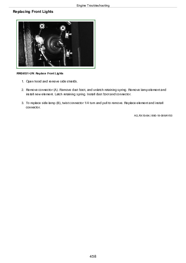
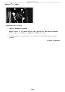
  Replacing Front Lights….458
  Adjusting Head Lights….459
  Replacing Roof Front Flood Light….460
  Replacing Roof Rear Flood Light….461
  Replacing Front Fender Floods….462
  Replacing Front Belt-Line Flood Light….463
  Replacing Front Warning Light….464
  Replacing Rear Warning Light….465
  Replacing Tail Light….466
Section 115: Troubleshooting….467
  Engine Troubleshooting….468
  Transmission Troubleshooting….473
  Hydraulic System Troubleshooting….474
  Brakes Troubleshooting….475
  Hitch Troubleshooting….476
  Selective Control Valve Troubleshooting….478
  Electrical System Troubleshooting….480
  Operator Enclosure Troubleshooting….483
  Tractor Operation Troubleshooting….485
Section 120: Storage….486
  Placing Tractor in Long-Term Storage….487
  Removing Tractor From Storage….488
  Paint Finish Care….489
Section 125: Specifications….491
  Specifications….491
  Ground Speeds-16-Speed PowrQuad and Creeper Transmission….490
  Ground Speeds-16-Speed PowrQuad and Creeper Transmission….490
  Ground Speeds-16-Speed PowrQuad and Creeper Transmission….490
  Ground Speeds-Hi-Crop with 16-Speed PowrQuad and Creeper Transmission….490
  Ground Speeds-Hi-Crop with 16-Speed PowrQuad and Creeper Transmission….490
  Ground Speeds-20-Speed PowrQuad and Creeper Transmission….490
  Ground Speeds-20-Speed PowrQuad and Creeper Transmission….490
  Ground Speeds-20-Speed PowrQuad and Creeper Transmission….490
  Metric Bolt and Cap Screw Torque Values….511
  Unified Inch Bolt and Cap Screw Torque Values….513
  Limited Battery Warranty….515
Section 130: Identification Numbers….516
  Identification Plates….517
  Record Tractor Identification Number….518
  Record Cab Identification Number….519
  Record Engine Identification Number….520
  Record Mechanical Front-Wheel Drive Identification Number-Version “A”….516
  Record Mechanical Front-Wheel Drive Identification Number-Version “B”….516
  Record Differential Case Identification Number….523
  Record Hi-Crop Axle Housing Identification Number….524
Section 135: Lubrication and Maintenance Records….525
  250 Hour Service Records….526
  750 Hour Service Records….527
  1500 Hour Service Records….528
  2000 Hour Service Records….529
  Annual Service Records….530
  Two Year Service Records….531
Section 140: Glossary….532
  Glossary of Terms….533
Section 145: Crime Prevention Tips….535
  Help Prevent Crime….536
  Record Ag Identification Numbers….537
  Keep Proof of Ownership….538
  Park Indoors Out of Sight….539
  When Parking Outdoors….540
  Reduce Vandalism….541
  Report Thefts Immediately….542
Section IBC: John Deere Service Keeps You on the Job….546
  John Deere Is At Your Service….547

John Deere 7210, 7410, and 7510 Tractors Operator’s Manual (OMAR189655)


INSTANT DOWNLOAD


Posted on

John Deere Models 7210, 7410, 7510 Tractors Repair Service Manual (TM1653)


INSTANT DOWNLOAD


Complete Repair Service Technical Manual for John Deere 2WD or MFWD Tractors 7210, 7410, and 7510, with workshop information to maintain, repair, and service like professional mechanics.

John Deere 2WD or MFWD Tractors 7210, 7410, and 7510 workshop technical manual (repair) includes:
* Numbered table of contents easy to use so that you can find the information you need fast.
* Detailed sub-steps expand on repair procedure information
* Numbered instructions guide you through every repair procedure step by step.
* Notes, cautions and warnings throughout each chapter pinpoint critical information.
* Bold figure number help you quickly match illustrations with instructions.
* Detailed illustrations, drawings and photos guide you through every procedure.
* Enlarged inset helps you identify and examine parts in detail.

TM1653 English – 7210, 7410, and 7510 Tractors Repair Technical Manual.pdf
tm2109 English – PRO-12™, PRO-12™ VRS, and PRO-16™ Picking Unit Repair Technical Manual

Total Pages: 1,281 pages
File Format: PDF (bookmarked, ToC, Searchable, Printable)
Language: English

ctm104 English – 4.5L AND 6.8L DIESEL ENGINES (BASE ENGINE) -: (WORLDWIDE EDITION) Component Technical Manual
ctm120519 English – Hydraulic Cylinders Component Technical Manual
ctm207 English – PowerTech™ 4.5L and 6.8L Diesel EnginesMechanical Fuel Systems -: (Worldwide Edition) Component Technical Manual
ctm284 English – POWERTECH® 4.5L & 6.8LDiesel EnginesLevel 1 Electronic Fuel SystemsWith Delphi (Lucas)DP201 Pump Component Technical Manual
ctm307 English – Air Conditioning Compressor Installation Manual
ctm4509 English – Front Wheel Drive Axles Component Technical Manual
ctm67 English – OEM Engine Accessories Component Technical Manual
ctm704219 English – Connectors Repair Component Technical Manual
ctm77 English – Alternators and Starter Motors Component Technical Manual
ctm9 English – Series 500 6619 Diesel Engines Component Technical Manual

MAIN SECTIONS
Foreword
Dealer Predelivery Service
Quick Reference Specifications
Safety
Safety
General Information
General Information
Engine
Component Removal and Installation
Engine Repair
Fuel, Air Intake, and Cooling Systems
Throttle Controls
Diesel Fuel System
Air Intake System
Engine Cooling System
Air Conditioning Condenser and Coolers
Electrical
Connectors
Wiring Harness Routing
Charging Circuit
Starting Circuit
Solenoids and Switches
Monitoring System
Auxiliary Lighting and Electrical Components
Convenience and Accessory Components
Transmission
Component Removal and Installation
Control Linkages
SyncroPlus Transmission
PowrQuad Transmission
Creeper Transmission
Range Box
Drive Systems
Component Removal and Installation
Controls
MFWD Clutch
MFWD Axle-Version “A”
MFWD Axle-Version “B”
Rear Differential
Final Drive
Hi-Crop Final Drive
PTO
Drivelines
Hydraulic Pump Drive
Steering and Brakes
Steering Column
Hydrostatic Steering
Steering Cylinders
Brake Valve
Brake Components
Hydraulics
Component Removal and Installation
Hydraulic System Repair
Hydraulic Pump and Charge Pump
Hydraulic System Valves
Selective Control Valves and Couplers
Rear Three-Point Hitch
Remote Cylinder
Row Guidance
Bleed Hydraulic System
Miscellaneous
Component Removal and Installation
Front Axle
Hood
Operator Station
Component Removal and Installation
Controls
Air Conditioning System
Heating System
Seat
ROPS and Cab
Dealer Fabricated Tools
Fabricated Tools
tm1653 – 7210, 7410, and 7510 Tractors Repair
Table of Contents
Foreword
Dealer Predelivery Service
Quick Reference Specifications
Section 05: Safety
Group 05: Safety
Handle Fluids Safely—Avoid Fires
Prevent Battery Explosions
Prepare for Emergencies
Prevent Acid Burns
Handle Chemical Products Safely
Avoid High-Pressure Fluids
Park Machine Safely
Support Machine Properly
Wear Protective Clothing
Work in Clean Area
Service Machines Safely
Work In Ventilated Area
Illuminate Work Area Safely
Replace Safety Signs
Use Proper Lifting Equipment
Service Tires Safely
Avoid Harmful Asbestos Dust
Avoid Heating Near Pressurized Fluid Lines
Remove Paint Before Welding or Heating
Use Proper Tools
Dispose of Waste Properly
Live With Safety
Section 10: General Information
Group 05: General Information
Specifications
Sealants and Adhesives Cross-Reference Chart
Metric Bolt and Cap Screw Torque Values
Unified Inch Bolt and Cap Screw Torque Values
Glossary Of Terms
Section 20: Engine
Group 00: Component Removal and Installation
Essential or Recommended Tools
Specifications
Remove Engine
Install Engine in Repair Stand
Install Engine
Group 05: Engine Repair
Repair Engine—Use CTM
Specifications
Access to Intake and Exhaust Valves
Access to Front Crankshaft Seal
Access to Rear Crankshaft Seal—With Creeper Transmission
Access to Rear Crankshaft Seal—Without Creeper Transmission
Access to Camshaft
Access to Timing Gear Cover
Remove and Install Engine Valve Cover
Section 30: Fuel, Air Intake, and Cooling Systems
Group 05: Throttle Controls
Repair Engine—Use CTM
Specifications
Adjust Hand—Foot Throttle with Mechanical Linkage
Group 10: Diesel Fuel System
Remove and Install Fuel Tank
Replace Fuel Filter, Fuel Pump, and Bleed Fuel System
Group 15: Air Intake System
Inspect and Service Air Intake System
Group 20: Engine Cooling System
Essential or Recommended Tools
Specifications
Test Radiator And Coolant Tank
Test Radiator Cap
Remove and Install Radiator
Remove and Install Viscous Fan Drive
Inspect Belt Tensioner
Replace Belt Tension Mechanism
Group 25: Air Conditioning Condenser and Coolers
Essential or Recommended Tools
Other Material
Specifications
Remove Hydraulic Oil Cooler/Condenser
Install Hydraulic Oil Cooler/Condenser
Leak Test Hydraulic Oil Cooler/Condenser
Section 40: Electrical
Group 05: Connectors
Essential or Recommended Tools
Other Material
Use Electrical Insulating Compound
Using High-Pressure Washers
Replace Weather Pack Weather Pack is a trademark of Packard Electric Connector
Install Weather Pack Weather Pack is a trademark of Packard Electric Contact
Remove Connector Body from Blade Terminals
Replace (Pull Type) METRI-PACK METRI-PACK is a trademark of Delphi Packard Electric Systems Connectors
Replace (Push Type) METRI-PACK METRI-PACK is a trademark of Delphi Packard Electric Systems Connectors
Replace CPC CPC is a trademark of AMP Inc , Large MATE-N-LOC MATE-N-LOC is a trademark of AMP Inc , and METRIMATE METRIMATE is a trademark of AMP Inc Pin Type Connectors
Replace CPC CPC is a trademark of AMP Inc Blade-Type Connectors
Replace Small MATE-N-LOC MATE-N-LOC is a trademark of AMP Inc Socket Connector
Replace Small MATE-N-LOC MATE-N-LOC is a trademark of AMP Inc Pin Connector
Replace DEUTSCH DEUTSCH is a trademark of Deutsch Company Connectors
Install DEUTSCH DEUTSCH is a trademark of Deutsch Company Contact
Replace Cinch Connectors
Group 10: Wiring Harness Routing
Ground Point Locations
Cab Harness Routing and Component Identification
Open Station Harness Routing and Component Identification
PowrQuad Transmission Harness Routing and Component Identification
SyncroPlus Transmission Harness Routing and Component Identification
Engine Harness Routing and Component Identification
Row Guidance Harness Routing and Component Identification
Wire Number and Color Codes
Load Center Fuses, Relays, and Diodes— Open Station
Load Center Fuses, Relays, and Diodes— Cab
Replace Load Center Fuses and Relays
Group 15: Charging Circuit
Repair Alternator—Use CTM
Remove Alternator
Install Alternator
Group 20: Starting Circuit
Essential or Recommended Tools
Specifications
Repair Starter—Use CTM
Remove and Install Starter Motor
Replace Starter Circuit Relay
Replace Fusible Link
Replace Neutral Start Switch—PowrQuad Transmission
Replace Neutral Start Switch—SyncroPlus Transmission
Group 25: Solenoids and Switches
Specifications
Replace Air Conditioning Relays and Switches
Replace Air Conditioning High and Low Pressure Switches
Replace MFWD Solenoid
Replace Differential Lock and Rear PTO Solenoids
Replace Fuel Shut-Off Solenoid
Replace Hitch Return and Hitch Pressure Solenoids
Replace and Install Hitch Position Potentiometer
Replace Hitch Control Potentiometer and Switch
Remove Electrical Switches and Sensors— PowrQuad Transmission
Remove Electrical Switches—SyncroPlus Transmission
Replace Brake Switch
Replace Thermo Starting Aid and Heater Relay
Group 30: Monitoring System
Essential or Recommended Tools
Other Material
Specifications
Replace Hydraulic Oil Restriction Sensor
Replace Engine Oil Pressure Sensor
Replace Air Filter Restriction Indicator Sensor
Replace Engine Speed Sensor
Replace Engine Coolant Temperature Sensor
Replace Fuel Level Sensor
Replace Wheel Speed Sensor
Replace Rear PTO Speed Sensor
Replace Radar Speed Sensor
Hitch-Position Feed-Back Sensor Location
Remove and Install Draft Link Sensor
Adjust Draft Link Sensor
Replace Hitch Control Unit (HCU) and Central Control Unit (CCU)
Replace Reverser Control Unit (RCU)
Remove and Install Display Console
Replace Display Module Bulbs
Replace Light Switch, Hazard Light Switch, and Audible Warning Alarm
Replace Multifunction and Washer Wiper Switch
Replace FNR Direction Switch
Replace Multifunction Switch Wiring Harness
Group 40: Auxiliary Lighting and Electrical Components
Replace Seven-Terminal Outlet Socket
Group 45: Convenience and Accessory Components
Replace Pressurized Blower Motor
Replace Circulation Blower Motors
Replace Wiper Motor
Test Ground Fault Circuit Interrupter
Replace Transmission Cover Heater
Replace Hydraulic Charge Pump Heater
Row Guidance Component Identification
Replace Row Guidance Coupler Position Sensor
Remove and Install Row Guidance Probe Angle Position Sensor and Probe Rise/Lower Motor Relay
Remove Row Guidance Probe Motor
Section 50: Transmission
Group 00: Component Removal and Installation
Essential or Recommended Tools
Other Material
Specifications
Sealing Instructions
Remove Drive Train
Install Drive Train
Remove SyncroPlus Clutch Housing
Install SyncroPlus Clutch Housing
Remove SyncroPlus Transmission
Install SyncroPlus Transmission
Remove PowrQuad Transmission
Install PowrQuad Transmission
Remove SyncroPlus Creeper Transmission
Install SyncroPlus Creeper Transmission
Remove PowrQuad Creeper Transmission
Install PowrQuad Creeper Transmission
Remove Range Box
Install Range Box
Group 05: Control Linkages
Essential or Recommended Tools
Other Material
Specifications
Shift Controls Introduction
Access Shift Console
Shift and Park Linkage Assembly
PowrQuad Shift and Park Linkage Symptom/Cause Chart—Two-Lever
Shift and Park Linkage Adjustment
Preliminary Checks—All
Shifter Cam Neutral Alignment—Two-Lever Shifter
Check Shifter Lever Tang and Fork Slot— Two-Lever Shifter
Adjust Park Stop Bolt—SyncroPlus
Check Shift Lever Pivot—Two-Lever Shifter and Three-Lever Shifter With Right-Hand Reverser
Inspect Shifter Cams—Two-Lever Shifter
Check and Adjust Cam Neutral Alignment— Two-Lever Shifter
Inspect F-N-R Lower Linkage—Two-Lever Shifter and Three-Lever Shifter With Right-Hand Reverser
Adjust F-N-R Lower Linkage—Two-Lever Shifter and Three-Lever Shifter With Right-Hand Reverser
Inspect and Adjust F-N-R Upper Linkage— Two-Lever Shifter
Adjust F-N-R—Three-Lever Shifter With Right-Hand Reverser
F-N-R Speed Select Shift Linkage Adjustment— SyncroPlus
Inspect and Adjust Lower Speed Linkage— Two-Lever Shifter and Three-Lever Shifter With Right-Hand Reverser
Inspect and Adjust Upper Speed Linkage— Two-Lever Shifter
Inspect and Adjust Upper Speed Linkage— Three-Lever Shifter
Inspect Lower Park Rod—All Shifters
Inspect Upper Park Rod and Check Park Adjustment— All Shifters
Adjust Park Rod—All Shifters
Adjust Park Rod With Turnbuckle—All Shifters
Adjust Park Rod With Balljoint—All Shifters
Check Park Rod For Excessive Flexing—All Shifters
Check and Adjust Park Disengaged Stop— Two-Lever Shifter
Lubricate Park Arm, Shifter Fork Slots and Shift Lever Tang—All Shifters
Adjust Range Linkage
Drive and Final Checks—Shifting and Park Performance
Other Symptoms and Solutions—Two-Lever Shifter and Three-Lever Shifter With Right-Hand Reverser
Remove Shift Control Assembly—Three-Lever Shifter
Exploded View—Three-Lever Shifter With Right-Hand Reverser
Disassemble Three-Lever Shifter Assembly With Right-Hand Reverser
Assemble Three-Lever Shifter With Right-Hand Reverser
Exploded View—Three-Lever Shifter With Left-Hand Reverser
Disassemble Three-Lever Shifter With Left-Hand Reverser
Assemble Three-Lever Shifter With Left-Hand Reverser
Exploded View—Two-Lever Shifter
Disassemble Two-Lever Shifter
Assemble Two-Lever Shifter
Remove Shift Control Assembly—SyncroPlus
Disassemble Shift Control Assembly—SyncroPlus
Exploded View—Shifter Assembly— SyncroPlus
Lower Shift Linkage—SyncroPlus
Recondition Lower Shift Linkage—SyncroPlus Without Creeper
Repair Lower Park Lock Outer Linkage—SyncroPlus
Recondition Park Lock—SyncroPlus
Replace Park Lock Disconnect Arm
Recondition Upper Shift Linkage—SyncroPlus
Creeper Control Lever
Exploded View—Lower Creeper Control Linkage
Adjust or Replace Clutch Cable (Non-Isolated)
Adjust or Replace Clutch Cable (Isolated)
Group 10: SyncroPlus Transmission
Essential Or Recommended Tools
Other Material
Specifications
General Repair Procedures—SyncroPlus Transmission
Cross-Sectional View—Clutch Housing
Remove Clutch
Exploded View—Clutch Components
Disassemble Clutch
Assemble Clutch
Install Clutch
Remove Transmission Oil Pump
Exploded View—Transmission Oil Pump Components
Disassemble Transmission Oil Pump
Assemble Oil Pump
Install Transmission Oil Pump
Exploded View—Clutch Housing Valves
Remove Clutch Pedal Valve
Install Clutch Pedal Valve
Cross-Sectional View—Transmission
Exploded View—Transmission
Exploded View—Shifter Components
Disassemble Transmission
Assemble Transmission Drive Shaft
Install Shafts
Adjust Shifting Mechanism
Final Assembly
Group 15: PowrQuad Transmission
Essential or Recommended Tools
Other Material
Specifications
General Repair Procedures—PowrQuad Transmission
Internal Components—PowrQuad Transmission
Install Transmission in Repair Stand
Remove Transmission Front Cover/Front Valve Housing
Remove Front Valve Housing
Front Valve Housing Valves
Transmission Front Cover Valves
Clutch Valve
Replace Clutch Valve Shifter Lever/Shaft Seal
Replace Clutch Valve Inner Arm/Shaft
Cross-Sectional View—Transmission Air Pump
Repair Transmission Air Pump
Install Front Valve Housing
Install Transmission Front Cover/Front Valve Housing
Remove Shift Control Valve Housing
Replace Forward-Reverse/Speed Selector Shifter Levers/Shaft Seals
Replace Forward-Reverse/Speed Selector Shifter Shafts/Shifter Arms
Shift Control Valve Housing Valves
Cross-Sectional View—Modulator Valve
Planetary Housing Valves
Cross-Sectional View—Forward/Neutral/Reverse Control Valve
Install Detent Springs
Cross-Sectional View—Forward/Reverse Control Valve
Cross-Sectional View—Speed Selector Valve
Assemble and Install Shift Valve Housing
Disassemble Planetary Assembly
Recondition Input Planetary Carrier
Disassemble Input Planetary Assembly
Disassemble Reverse Brake Housing Components
Cross-Sectional View—Forward Clutch Assembly
Recondition Forward Clutch Assembly
Disassemble Planetary Housing Components
Cross-Sectional View—Direct Drive Clutch Assembly
Recondition Direct Drive Clutch Assembly
Assemble Planetary Housing Components
Assemble Reverse Brake Housing Components
Assemble Input Planetary Carrier
Assemble Input Planetary Assembly
Group 20: Creeper Transmission
Essential or Recommended Tools
Other Material
Specifications
General Repair Procedures—Creeper Transmission
Recondition Creeper Transmission
Cross-Sectional View—Shifter Components
Remove and Install Shifter Components
Cross-Sectional View—Creeper Transmission
Remove Input/Output Drive Shaft Assembly
Disassemble and Assemble Drive Shaft/Snubber Brake
Remove and Install Countershaft
Install Input/Output Shaft Assembly
Group 25: Range Box
Essential or Recommended Tools
Other Material
Specifications
General Repair Procedures—Range Box
Recondition Neutral Centering System
Remove and Disassemble Shifter Cover
Remove and Install Park Pawl
Cross-Sectional View—Shifter Rails
Remove Shifter Rails and Forks
Install and Adjust Shifter Forks and Rails
Assemble and Install Shifter Cover
Remove Differential Drive Shaft
Cross-Sectional View—Differential Drive Shaft
Determine Cone Point Shim Pack and Install Differential Drive Shaft
Cross-Sectional View— Input Shaft (30K)
Cross-Sectional View— Input Shaft (40K)
Remove and Disassemble Input Shaft
Assemble and Install Input Shaft
Adjust Input Shaft End Play
Section 56: Drive Systems
Group 00: Component Removal and Installation
Essential or Recommended Tools
Other Material
Specifications
Sealing Instructions
MFWD Axle Identification—Version “A” and “B”
Remove MFWD Clutch
Install MFWD Clutch
Remove MFWD Axle
Install MFWD Axle
Remove Rear PTO Assembly
Install Rear PTO Assembly
Remove Standard Final Drive
Prepare Splitting Stand
Install Standard Final Drive
Remove Hi-Crop Final Drive
Install Hi-Crop Final Drive
Group 05: Controls
Specifications
PTO Switch
MFWD Switch
MFWD Solenoid
Differential Lock Switch
Differential Lock Solenoid
PTO Clutch Solenoid
PTO Speed Sensor
Group 10: MFWD Clutch
Essential Tools or Recommended Tools
Specifications
General Repair Procedures—MFWD Clutch
Cross-Sectional View—MFWD Clutch
Disassemble MFWD Clutch
Disassemble MFWD Clutch Pack
Assemble MFWD Clutch Pack
Assemble MFWD Clutch
Group 15: MFWD Axle—Version “A”
Essential or Recommended Tools
Other Material
Specifications
General Repair Procedures—MFWD Axle
MFWD Axle Identification—Version “A” and Version “B”
Cross Sectional View—Planetary Carrier, Wheel Hub, and Knuckle Spindle
Remove and Disassemble Planetary Carrier
Assemble and Install Planetary Carrier
Remove and Install Axle Housing
Remove and Disassemble Knuckle Spindle Assembly
Install Knuckle Spindle Assembly
Input Quill and Differential Drive Shaft
Remove and Disassemble Input Quill and Differential Drive Shaft
Determine Differential Drive Shaft Cone Point Shim Pack
Assemble and Install Differential Drive Shaft
Adjust Differential Drive Shaft End Play
Install Input Quill
Remove Differential
Cross-Sectional View—Differential Assembly
Disassemble Differential
Assemble Differential
Remove and Install Ring Gear
Install Differential
Adjust Differential Rolling Drag Torque
Adjust Differential Backlash
Replace Pivot Pin Bushing
Group 16: MFWD Axle—Version “B”
Essential or Recommended Tools
Other Material
Specifications
General Repair Procedures—MFWD Axle
MFWD Axle Identification—Version “A” and Version “B”
Cross-Sectional View—Planetary Carrier and Wheel Hub
Remove and Recondition Planetary Carrier and Wheel Hub
Assemble and Install Planetary Carrier and Wheel Hub
Cross-Sectional View—Knuckle Spindle Assembly
Disassemble, Inspect, and Assemble Knuckle Spindle Assembly
Install MFWD Axle Into Repair Stand
Cross-Sectional View—Planetary Carrier Assembly
Remove and Install Planetary Carrier Assembly
Determine Kingpin Shim Pack
Remove Differential Housing
Cross-Sectional View—Differential Housing
Recondition Differential Housing
Assemble Differential
Cross-Sectional View—Differential Drive Shaft and Input Quill
Remove and Disassemble Differential Drive Shaft
Determine Differential Drive Shaft Cone Point Shim Pack
Assemble and Install Differential Drive Shaft
Check Ring Gear Backlash and Determine Differential Case Bearing Cup Shim Pack
Adjust Ring Gear Backlash
BACKLASH SHIM PACK EXAMPLE AND WORKSHEET
Install Differential Case Bearing Cup and Differential Housing
Disassemble and Assemble Axle Housing
Determine and Install Axle Housing Bearing Cup Shim Pack
Bearing Cup Shim Procedure
PRELOAD SHIM PACK EXAMPLE AND WORKSHEET
Install Axle Housing
Cross-Sectional View—Steering Cylinder Housing Assembly
Remove and Disassemble Steering Cylinder
Cross-Sectional View—Steering Cylinder
Assemble and Install Steering Cylinder
Group 20: Rear Differential
Essential or Recommended Tools
Specifications
General Repair Procedures—Rear Differential
Remove Differential
Cross-Sectional View—Rear Differential
Disassemble Rear Differential
Assemble Rear Differential
Adjust Differential Preload
Adjust Differential Backlash
Group 25: Final Drive
Essential or Recommended Tools
Other Material
Specifications
General Repair Procedures—Final Drive
Repair Axle Housing Oil Seal Leaks
Cross-Sectional View—Final Drive—80 mm Axle Shaft
Remove Planet Pinion Carrier
Disassemble Planet Pinion Carrier
Exploded View—Planet Pinion Carrier
Assemble Planet Pinion Carrier
Remove Axle Housing
Disassemble and Assemble Axle Housing
Disassemble and Assemble Axle Shaft
Axle Shaft Outer Bearing Diameter
Install Axle Housing
Install Planet Pinion Carrier And Check Rolling Drag Torque (Non-Shimmed Axles)
Install Planet Pinion Carrier And Check Rolling Drag Torque (Shimmed Axles)
Group 30: Hi-Crop Final Drive
Essential or Recommended Tools
Other Material
Specifications
General Repair Procedures—Hi-Crop Final Drive
Cross-Sectional View—Hi-Crop Final Drive
Disassemble Final Drive
Assemble Final Drive
Group 35: PTO
Essential or Recommended Tools
Specifications
General Repair Procedures—PTO Clutch
Repair PTO
Cross-Sectional View—PTO Clutch
Remove and Disassemble PTO Clutch
Assemble and Install PTO Clutch
Remove and Disassemble Countershaft
Cross-Sectional View—PTO Countershaft
Assemble and Install PTO Countershaft
Cross-Sectional View—PTO Output Shaft
Remove and Disassemble PTO Output Shaft
Assemble and Install PTO Output Shaft
Replace PTO Output Shaft Oil Seal
Remove PTO Valve Housing
Disassemble and Assemble PTO Valve Housing
Install PTO Valve Housing
Group 40: Drivelines
Specifications
MFWD Drive Shaft
Engine Coupler Shaft
Group 45: Hydraulic Pump Drive
Essential or Recommended Tools
Specifications
General Repair Procedures—Pump Drive
Cross-Sectional View—Hydraulic Pump Drive
Remove and Disassemble Pump Drive Pinion Gear
Remove and Disassemble Pump Drive Gear
Assemble and Install Pump Drive Gear
Assemble and Install Pump Drive Pinion
Check and Adjust Pump Drive Gear Backlash
Section 60: Steering and Brakes
Group 05: Steering Column
Specifications
Repair Steering Column
Repair Steering Housing Assembly
Group 10: Hydrostatic Steering
Essential or Recommended Tools
Specifications
Remove and Install Steering Valve
Exploded View—Steering Valve
Disassemble, Inspect, and Assemble Steering Valve
Group 15: Steering Cylinders
Specifications
Other Material
Service Parts Kits
MFWD Axle Identification—Version “A” and Version “B”
Remove and Install Steering Cylinder
Cross-Sectional and Exploded View—Steering Cylinder Two-Wheel Drive
Cross-Sectional and Exploded View—Steering Cylinder Version “A” MFWD Axle
Group 20: Brake Valve
Service Parts Kits
Specifications
General Repair Procedures—Brake Valve
Remove and Install Brake Valve
Disassemble, Inspect, and Assemble Brake Valve
Bleed Brakes
Check Manual Brakes
Group 25: Brake Components
Specifications
Remove, Inspect, and Install Brake Pistons, Plates, and Disks
Section 70: Hydraulics
Group 00: Component Removal and Installation
Essential or Recommended Tools
Specifications
Remove Hitch—SCV Assembly
Remove and Install Main Hydraulic Pump
Remove and Install Charge Pump
Group 05: Hydraulic System Repair
Essential or Recommended Tools
Specifications
General Repair Procedures—Hydraulic Systems
Use Special Wrench
Install Hydraulic Fittings
Drain Hydraulic System
Fill Hydraulic System
Group 10: Hydraulic Pump and Charge Pump
Essential or Recommended Tools
Other Material
Service Parts Kits
Specifications
General Repair Procedures—Hydraulic Pumps
Remove and Install Hydraulic Pump Controller
Exploded View—Hydraulic Pump Controller
Disassemble, Inspect, and Assemble Pump Controller
Exploded View—25 cm 3 (1.5 in.3) Hydraulic Pump
Exploded View—40 Cm 3 (2.4 In.3) Hydraulic Pump
Disassemble, Inspect, and Assemble Hydraulic Pump
Adjust Yoke Bearing Preload
Adjust Shaft Bearing Preload 40 cm 3 (2.4 in.3) Pump
Inspect Hydraulic Charge Pump
Group 15: Hydraulic System Valves
Essential or Recommended Tools
Service Parts Kits
Specifications
General Repair Procedures—Hitch and Inlet-Priority Valves, and Filter Bypass
Remove, Inspect, and Install Hydraulic Filter Bypass
Disassemble, Inspect, and Assemble Inlet-Priority Valve
Remove and Install Hitch Valve
Disassemble, Inspect, and Assemble Hitch Valve
Adjust Hitch Valve
Group 20: Selective Control Valves and Couplers
Essential or Recommended Tools
Other Material
Service Parts Kits
Specifications
General Repair Procedures—Selective Control Valves and Couplers
Remove, Install, and Adjust SCV Linkage
Remove, Install, And Adjust SCV Cable Linkage
SCV Identification
Remove, Inspect, and Install Selective Control Valves
Selective Control Valve—Exploded View— Three-Position
Selective Control Valve—Exploded View— Two-Position
Exploded View—Selective Control Valve— Single-Position
Replace Control Knobs
Inspect Poppet Load-Check Valves
Inspect Pressure CompensatorValve— Three-Position SCV
Inspect Metering Valve— Three-Position SCV
Inspect Metering Valve— Two-Position SCV
Disassemble, Inspect, and Assemble Control Valve— Three-Position SCV
Disassemble, Inspect, and Assemble Control Valve— Two-Position SCV
Disassemble, Inspect, and Assemble Control Valve— Single-Position SCV
Disassemble, Inspect, and Assemble Couplers
Group 25: Rear Three-Point Hitch
Essential or Recommended Tools
Other Material
Specifications
Remove and Install Lift Cylinders
Cross-Sectional and Exploded View—Lift Cylinder
Replace Rockshaft Housing Bushings 7210 (xxxx—010370) 7410 (xxxx—010506)
Replace Rockshaft Housing Bushings 7210 (010371—xxxx) 7410 (010507—xxxx) And All 7510
Repair Draft Link
Repair Draft Sensing
Group 30: Remote Cylinder
Specifications
Disassemble and Inspect Remote Cylinder
Assemble and Bleed Remote Cylinder
Group 35: Row Guidance
Service Parts Kits
Specifications
Remove and Install Probe Module
Repair Row Guidance Cylinder
Exploded View—Row Guidance Cylinder
Group 40: Bleed Hydraulic System
Essential or Recommended Tools
Bleed Hydraulic System
Section 80: Miscellaneous
Group 00: Component Removal and Installation
Essential or Recommended Tools
Specifications
Remove and Install Front Axle
Group 05: Front Axle
Other Material
Specifications
Replace Knee Bushings
Group 10: Hood
Adjust Hood
Section 90: Operator Station
Group 00: Component Removal and Installation
Specifications
Remove Cab
Install Cab
Group 05: Controls
Essential or Recommended Tools
Specifications
Remove, Install, and Adjust Temperature Control Cable
Remove, Install, and Adjust Air Flow Control Cable
Remove and Install Air Plenum
Remove and Install Air Manifold
Remove and Install Loader/4TH SCV Control Lever
Group 10: Air Conditioning System
Essential or Recommended Tools
Other Material
Service Parts Kits
Specifications
Hose and Tubing O-Ring Connection Torques
Diagram—Air Conditioning System
Air Conditioning System Fitting—Reference Chart
Leak Test With Dye
Discharge Air Conditioning System
Remove and Install Compressor
Test Volumetric Efficiency
Test Shaft Seal Leakage
Disassemble and Assemble Compressor Clutch
Check Clutch Hub Clearance
Inspect Compressor Manifold
Disassemble, Inspect, and Assemble Compressor
Remove and Install Compressor Relief Valve
Replace Receiver-Dryer
Leak Test Condenser
Remove Evaporator-Heater Core
Leak Test Evaporator-Heater Core
Install Evaporator-Heater Core
Service Expansion Valve
System Information
Flush Air Conditioning System
Refrigerant Oil Information
Check Compressor Oil Charge
Determine Correct Refrigerant Oil Charge
Add Refrigerant Oil to System
Add Refrigerant Oil to Pressurized System
Purge Air Conditioning System
Evacuate Air Conditioning System
Charge Air Conditioning System
Group 15: Heating System
Remove Heater Control Valve
Test Heater Control Valve
Install Heater Control Valve
Group 20: Seat
Essential Or Recommended Tools
Other Material
Remove Seat and Mechanical Suspension
Disassemble, Inspect, and Assemble Mechanical Suspension Assembly
Install Mechanical Suspension Assembly
Remove Seat and Air Suspension
Remove Seat from Suspension
Remove Swivel Plate
Disassemble, Inspect, and Assemble Air Suspension Assembly
Install Seat and Air Suspension
Group 25: ROPS and Cab
Specifications
Check ROPS
Repair Cab Door Latch
Cab Door Adjustment—Step 1
Cab Door Adjustment— Step 2
Cab Door Adjustment— Step 3
Cab Door Adjustment— Step 4
Cab Door Adjustment— Step 5
Section 99: Dealer Fabricated Tools
Group 05: Fabricated Tools
Fabricated Tools
DFRW4—Axle Wheel Hub Tool
DFRW11—Differential Side Bevel Gear End Play Tool
DFRW20—Compressor Holding Fixture
DFRW29—Final Drive Housing Adapter
DFRW30—Axle Jacking Tool
DFRW60-DFRW61-DFRW62—Extension Harnesses
Extension Harnesses
DFRW63-DFRW64-DFRW65-DFRW66-DFRW81—Tap-Out Harnesses
DFRW70—Holding Tool
DFRW77—Rear Tractor Access Platform
DFRW78—Seat Support Tray
DFRW79—Piston Holding Tool
DFRW108—Park Rod Adjusting Nut Tool
DFRW117—Transmission-Hydraulic Flusher
DFRW132—Differential Side Bevel Gear End Play Tool
DFRW139—Thermal Expansion Valve Replacement Tool

John Deere Tractors 7210, 7410, 7510 Repair Service Manual (TM1653)


INSTANT DOWNLOAD


Posted on

John Deere Tractors 7210, 7410, and 7510 Diagnostics Service Technical Manual (TM1654)


INSTANT DOWNLOAD


Complete Diagnostics Technical Manual with electrical wiring diagrams for John Deere Tractors 2WD / MFWD 7210, 7410, 7510, with all the workshop information to maintain, diagnose, and service like professional mechanics.

John Deere 7210, 7410, 7510 Tractors workshop Diagnostics & Tests technical manual includes:
* Numbered table of contents easy to use so that you can find the information you need fast.
* Detailed sub-steps expand on repair procedure information
* Numbered instructions guide you through every repair procedure step by step.
* Troubleshooting and electrical service procedures are combined with detailed wiring diagrams for ease of use.
* Notes, cautions and warnings throughout each chapter pinpoint critical information.
* Bold figure number help you quickly match illustrations with instructions.
* Detailed illustrations, drawings and photos guide you through every procedure.
* Enlarged inset helps you identify and examine parts in detail.

tm1654 – 7210, 7410 and 7510 Tractors Technical Manual (Operation & Tests).pdf

Total Pages: 1,614 pages
File Format: PDF (bookmarked, ToC, Searchable, Printable)
Language: English

ctm104 English – 4.5L AND 6.8L DIESEL ENGINES (BASE ENGINE) -: (WORLDWIDE EDITION) Component Technical Manual
ctm120519 English – Hydraulic Cylinders Component Technical Manual
ctm207 English – PowerTech™ 4.5L and 6.8L Diesel EnginesMechanical Fuel Systems -: (Worldwide Edition) Component Technical Manual
ctm284 English – POWERTECH® 4.5L & 6.8LDiesel EnginesLevel 1 Electronic Fuel SystemsWith Delphi (Lucas)DP201 Pump Component Technical Manual
ctm307 English – Air Conditioning Compressor Installation Manual
ctm4509 English – Front Wheel Drive Axles Component Technical Manual
ctm67 English – OEM Engine Accessories Component Technical Manual
ctm704219 English – Connectors Repair Component Technical Manual
ctm77 English – Alternators and Starter Motors Component Technical Manual
ctm9 English – Series 500 6619 Diesel Engines Component Technical Manual

MAIN SECTIONS
Foreword
Safety Information
Safety
General Information
Operational Checkout
General Reference Information
Test Equipment Calibration
Diagnostic Trouble Codes
CCU Code Diagnostics
HCU Code Diagnostics
LHP Code Diagnostics
RCU Code Diagnostics
Observable Symptoms
Brakes
Operator Station
Hydraulics
Engine
General Information
Fuel, Air Intake and Engine Cooling Systems
Fuel/Air/Cooling System Theory of Operation
Electrical System
Diagnostic Codes and Addresses
Electrical System Information
System Diagrams
System Diagram References
System Functional Schematic (CAB)
System Functional Schematic (OOS)
Wiring Harnesses
Sub-System Diagnostics
Starting, Power and Charging Circuit Diagnostics
Wiper and Seat Circuit Diagnosis
Ground Fault Circuit Interrupter Diagnosis
Air Quality System (AQS) Diagnosis
Radio, Horn, Dome Lamp and Multi-Function Control Circuit
Lighting Circuit Diagnosis
Accessory Connector and Lighter Circuit Diagnosis
Hitch Control Diagnosis
CCU Diagnosis
Differential Lock Circuit
MFWD Circuit
Rear PTO Circuit
Wheel and Radar Speed Circuit
Engine Speed Sensor Circuit
Fuel Level Sender Circuit
System Voltage Circuit
Engine Coolant Temperature Sensor
Hydraulic Oil Temperature Circuit
Engine Oil Pressure Sensor Circuit
Transmission Oil Pressure Circuit
Air Filter Restriction Sensor Circuit
Transmission Oil Filter Restriction Sensor Circuit
Hydraulic Oil Filter Restriction Sensor Circuit
Sensor Excitation Power Circuit
Engine Hours and Engine Starts
Fuel Timing Advance Circuit
Display Modules
PowrQuad Control Circuit
ROW-TRAK Control Circuit
CCD Communication
Calibration
CCU Calibration
Performance Monitor Calibration and Diagnostic Tool
Battery References
Transmissions
Operational Checks
Transmission And Reverser Diagnosis
PowrQuad PowrQuad is a trademark of Deere & Company.
Diagnosis
Reverser Control Unit (RCU)
SyncroPlus SyncroPlus is a trademark of Deere & Company.
Diagnosis
Theory Of Operation
PowrQuad PowrQuad is a trademark of Deere & Company.
Theory of Operation
Reverser Control Unit (RCU) Theory of Operation
SyncroPlus SyncroPlus is a trademark of Deere & Company.
Theory of Operation
Drive Systems
Operational Checks
Drive System Diagnosis
Adjustments
Theory of Operation
Steering and Brakes
Steering and Brakes Theory of Operation
Hydraulic System
Operational Checks
Hydraulic System Diagnosis
Tools and Safety
Diagnostic Guidelines
Preliminary Checks
Hydraulic Diagnosis
Additional Troubleshooting Information
Hitch Electrical Diagnosis
HCU Additional Tests
ROW-TRAKROW-TRAK is a trademark of Deere & Company
Tests
Calibrations and Adjustments
Hitch Calibrations and Adjustments
ROW-TRAK™ Calibrations and Adjustments
Theory of Operation
Hydraulic System Diagrams
Hydraulic Control Circuit
Steering Circuit
Selective Control Valves (SCV)
Hitch
Electro-Hydraulic Depth Control
Headland Management Systems (HMS)
Hitch Dampening
Operator Station
Operational Checks
Air Conditioning System Diagnosis
Air Conditioning Theory of Operation
Dealer Fabricated Tools
tm1654 – 7210, 7410 and 7510 Tractors
Table of Contents
Foreword
Section 205: Safety Information
Group 05: Safety
Recognize Safety Information
Prevent Machine Runaway
Handle Fluids Safely—Avoid Fires
Prevent Battery Explosions
Prepare for Emergencies
Handle Starting Fluid Safely
Prevent Acid Burns
Service Cooling System Safely
Handle Chemical Products Safely
Avoid High-Pressure Fluids
Park Machine Safely
Support Machine Properly
Wear Protective Clothing
Service Machines Safely
Work In Ventilated Area
Work in Clean Area
Remove Paint Before Welding or Heating
Avoid Heating Near Pressurized Fluid Lines
Illuminate Work Area Safely
Replace Safety Signs
Use Proper Lifting Equipment
Keep ROPS Installed Properly
Service Tires Safely
Avoid Harmful Asbestos Dust
Protect Against High Pressure Spray
Practice Safe Maintenance
Use Proper Tools
Dispose of Waste Properly
Live With Safety
Section 210: General Information
Group 05: Operational Checkout
Before You Start
Lighting Circuit Operation
Transmission Checks
Hydraulic System Checks
Hitch System Checks
Air Conditioning System Checks
Group 10: General Reference Information
Specifications
JT03412—Supplemental Pressure Test Kit
JT03413—Supplemental Flow Test Kit
JT03419—ORFS Fitting Kit
JT05406—Master Hydraulic Flow Test Fitting Kit
JT05469—Flowmeter Kit
JT05470—Agricultural Universal Pressure Test Kit
Required Test Fittings
List of Diagnostic Adapters— ORFS
Unified Inch Bolt and Cap Screw Torque Values
Metric Bolt and Screw Torque Values
JIC Hydraulic Symbols
Glossary of Terms
Group 15: Test Equipment Calibration
JDG282 Temperature Gauge Check
Calibration Check of Flow Meters
Method No. 1: Flow Meter (Main Pump Quick Check from SCV)
Method No. 2: Volume Check From Flow Meter
Pressure Gauge Calibration Checker
Section 211: Diagnostic Trouble Codes
Group CCU: CCU Code Diagnostics
CCU 001 – Fuel Level Sender Circuit
CCU 010 – Engine Coolant Temperature High
CCU 011 – Engine Coolant Temperature Very High
CCU 012 – Coolant Temperature Sensor / Circuit Open
CCU 013 – Coolant Temperature Sensor / Circuit Shorted
CCU 015 – Hydraulic Oil Temperature High
CCU 016 – Hydraulic Oil Temperature Very High
CCU 017 – Hydraulic Oil Temperature Sensor Circuit Open
CCU 018 – Hydraulic Oil Temperature Sensor Circuit Shorted
CCU 021 – Engine Oil Pressure Low (Pressure Switch)
CCU 026 – Transmission Oil Pressure Low
CCU 030 – Engine Air Filter Restricted
CCU 035 – Transmission Oil Filter Restricted
CCU 045 – System Voltage Too Low (Idle-to-1500 rpm)
CCU 046 – System Voltage Too Low (Above 1500 rpm)
CCU 047 – System Voltage Too High (Engine running)
CCU 050 – Hydraulic Oil Filter Restricted
CCU 067 – Power to Sensor Circuits has Failed
CCU 072 – Rear PTO Control Switch Failed
CCU 073 – Rear PTO Output Driver Circuit Failed (Driver Commanded ON)
CCU 075 – Rear PTO Speed Not Present After PTO ON
CCU 078 – Front PTO Switch OFF But Solenoid ON
CCU 079 – Front PTO Switch ON But Solenoid OFF
CCU 080 – Differential Lock Switch ON at Start-Up
CCU 081 – Differential Lock Circuit Failed During Operation
CCU 085 – MFWD Control Switch Error
CCU 086 – MFWD Circuit Fault With Switch OFF
CCU 093 – Clutch Cooling Driver Fault
CCU 094 – Fuel Advance Output Driver Circuit Failure
CCU 101 – Clutch Cooling Not Allowed On This Controller
CCU 102 – HMS Not Allowed On This Controller
CCU 103 – Hitch Is Preventing HMS From Being Enabled Because Towed Implement Mode Is Active
CCU 104 – Remote PTO Not Allowed On This Controller
CCU 105 – Self Cancelling Turn signals Not Allowed
CCU 106 – Stuck HMS Switch At Power Up
CCU 125 – Both Turn Signals Are Active On This Controller
Group HCU: HCU Code Diagnostics
HCU 022 – Battery Voltage Out of Range
HCU 027 – Calibration Not Successful
HCU 028 – Calibration Memory Failure
HCU 029 – Calibration Selected For Less Than 30 Seconds (Also Recalls “EOC” Message)
HCU 041 – Pressure Valve Solenoid Circuit
HCU 042 – Return Valve Solenoid Circuit
HCU 043 – Pressure Valve Solenoid Circuit
HCU 044 – Return Valve Solenoid Circuit
HCU 045 – Sensor Supply Voltage Out of Range
HCU 048 – Auxiliary Input Circuit Fault
HCU 049 – Raise/Lower Rocker Switch Circuit
HCU 050 – HCU Failure
HCU 052 – Draft Sensor Circuit
HCU 053 – Load/Depth Control Potentiometer Circuit
HCU 054 – Hitch Control Lever Potentiometer Circuit
HCU 055 – Hitch Position Feedback Sensor Circuit
HCU 056 – Raise Limit Control Potentiometer Circuit
HCU 057 – Rate-of-Drop Control Potentiometer Circuit
HCU 058 – External Raise/Lower Switch Circuit
HCU 060 – CCD Communication Line Failure
HCU 090 – Hitch Raise Disabled Due to Low Oil Level
Group LHP: LHP Code Diagnostics
LHP 022 – Battery Voltage Out of Range
LHP 027 – Calibration Not Successful
LHP 028 – Calibration Memory Failure or Never Calibrated
LHP 029 – Calibration Selected For Less Than 30 Seconds
LHP 045 – Sensor Supply Voltage Out of Range
LHP 050 – RowTrak Control Unit Failure
LHP 054 – Position Control Circuit
LHP 055 – Pivot Angle Circuit
LHP 056 – Response Rate Control Circuit
LHP 057 – Row Sensor Circuit
LHP 058 – Row Sensor Raise Circuit
LHP 059 – Row Sensor Lower Circuit
LHP 060 – CCD Communication Line Failure
LHP 141 – Extend Valve Solenoid Circuit
LHP 142 – Retract Valve Solenoid Circuit
LHP 143 – Extend Valve Solenoid Circuit
LHP 144 – Retract Valve Solenoid Circuit
Group RCU: RCU Code Diagnostics
RCU 015 – Detent Status Fault Detected
RCU 016 – Park Detected With Wheel Speed and Valid Direction
RCU 017 – Serial EEPROM Failure In Non-Critical Memory
RCU 019 – Reverse Lockout Input And Park Input
RCU 025 – Detent Solenoid Circuit Fault
RCU 027 – Enable Pressure Not Detected
RCU 029 – Enable Valve Stuck Open or Enable Pressure Switch Failed Open
RCU 031 – Enable Solenoid Valve Or FWD Or Rev Relay Circuit Fault
RCU 032 – In Park Without Valid Neutral
RCU 034 – Reverser Lever In Direction Too Long While In Park (Diagnostic Mode Only)
RCU 035 – Missing Neutral Message From CCU. Can Not Detect Proper State Of Neutral Switch
RCU 040 – Forward and Reverse Switches Are Open, But NN Switch Is Closed Or Transmission Enable Is High
RCU 041 – Forward and Reverse Switches Are Closed At The Same Time
RCU 042 – Forward Switch Is Closed, But NN Switch Is Open
RCU 043 – Reverse Switch Is Closed, But NN Switch Is Open
RCU 044 – Not-Neutral Relay Failed Open
RCU 045 – Direction Commanded With Enable Valve Off
RCU 047 – Valid Neutral Not Detected After Power Up
RCU 048 – System Voltage Below 8 Volts
RCU 050 – Shuttle Shift Detected Without Neutral Indication
RCU 051 – Direction Is Commanded, But FNR Valve Is Not In Neutral
RCU 052 – High Range Detected While In Reverse
RCU 053 – Reverser Lever Is In Neutral But FNR Valve Is Not In Neutral
RCU 054 – Wheel Speed Detected In Diagnostic Mode
RCU 055 – Enable Valve Stuck Closed (No Flow)
RCU 056 – Powered Up With Reverser Lever In Direction
RCU 057 – Transmission Enable Signal Low During Operation
RCU 058 – Start in Gear Circuit Failure
RCU 064 – Power Up-Recoverable Fault In Critical Memory
RCU 065 – Power Up-Recoverable Fault In Critical Memory. Controller Will Attempt Correction
RCU 067 – Neutral Switch Indicates Not Neutral Without Cause
Section 212: Observable Symptoms
Group 10: Brakes
Brakes Function Erratically
Group 30: Operator Station
Poor AM & FM Radio Reception or Electrical Noise
Group 70: Hydraulics
Grapple Valve Holds System Pressure Above Standby for Several Seconds
Section 220: Engine
Group 05: General Information
Engine Operation and Tests
Specifications
Fuel and Cooling System
Section 230: Fuel, Air Intake and Engine Cooling Systems
Group 25: Fuel/Air/Cooling System Theory of Operation
Fuel System
Engine Cooling System
Air Intake System
Section 240: Electrical System
Group 04: Diagnostic Codes and Addresses
Enter/Exit “Diagnostic” Mode
Clear Diagnostic Codes
Diagnostic Codes
CCU Diagnostic Code Numbers
HCU Diagnostic Code Numbers
LHP Diagnostic Code Numbers
RCU Diagnostic Code Numbers
CCU Addresses
CCU Addresses 13—21
CCU Address Numbers 22-37
CCU Address Numbers 38 – 99
HCU Addresses
LHP Addresses
PrF Addresses
RCU Addresses
Group 05: Electrical System Information
Service Equipment and Tools
Other Material
Specifications
Using Electrical Section
Wiring Diagram and Schematic Information
Electrical Schematic Symbols
Reading a System Functional Schematic
Reading a Wiring Diagram
Reading a Diagnostic Schematic
Visually Inspect Electrical System
Seven Step Electrical Test Procedure With probe light or multimeter.
Electronic Circuit
Understanding Electrical Vs Electronic Circuit Voltage Test Readings
Voltage Test
Electrical Circuit
Circuit Malfunctions
High Resistance Circuit
Open Circuit
Grounded Circuit
Shorted Circuit
Locations of Circuit Malfunctions
Troubleshooting High Resistance or Open Circuits
Troubleshooting a Grounded Circuit
Troubleshooting Shorted Circuits
Short Circuit
Intermittent Electronic Problems
Repairing Shorted Circuits
Group 10: System Diagrams
System Diagrams
Group 10A: System Diagram References
Ground Point Locations
Ground Stud
Wiper Ground
Component Identification Table
Component Identification Legend
Group 10B: System Functional Schematic (CAB)
Legend For System Functional Schematics (Cab)
System Functional Schematic (Cab) SE1, SE2, SE3
System Functional Schematic (Cab) SE4, SE5
System Functional Schematic (Cab) SE6, SE7
System Functional Schematic (Cab) SE8
System Functional Schematic (Cab) SE9, SE10
System Functional Schematic (Cab) SE11
System Functional Schematic (Cab) SE13
Group 10C: System Functional Schematic (OOS)
Legend For System Functional Schematics (OOS)
System Functional Schematic (OOS) SE1, SE2, SE3, SE4
System Functional Schematic (OOS) SE5, SE6
System Functional Schematic (OOS) SE7, SE8
Group 10D: Wiring Harnesses
Fuse Panel (F1-F12)
Fuse Panel (F13-F20)
Fuse Panel (F21-F35)
Load Center Relays (K1-K5)
Load Center Relays (K6-K9)
Load Center Relays (K10-K18)
Diode Blocks (W2, W28) (V2—V3)
Cab Harness (W2)
Cab Harness
Cab Harness (W2)
Cab Harness (W2)
Open Operator Station Harness (W28)
Open Operators Station Harness (W28)
Engine Harness (W6)
Transmission Sensor Harness (W8)— PowrQuad PowrQuad is a trademark of Deere & Company.
Transmission Sensor Harness (W22)— SyncroPlus SyncroPlus is a trademark of Deere & Company.
Multi-Function Controls Harnesses (W15 & W16)
Roof Lights and Hitch Controls Harnesses (W11 & W14)
Air Suspension Seat and Mechanical Suspension Seat Harnesses (W25 & W26)
Front Floods and Convenience Outlet Harnesses (W13 & W17)
Cab Harness Routing and Component Location
Open Operator Station Harness Routing/Component Location
Open operator Station Harness Routing and Component Locations
Transmission Sensor Harness— SyncroPlus SyncroPlus is a trademark of Deere & Company.
Harness Routing and Component Identification— PowrQuad PowrQuad is a trademark of Deere & Company. Transmission
Engine Harness Routing and Component Location
ROW-TRAK ROW-TRAK is a trademark of Deere & Company. Harness Routing and Component Identification
Group 15: Sub-System Diagnostics
Reference List
Group 15A: Starting, Power and Charging Circuit Diagnostics
Starting Circuit (SE1)
Starting Circuit Operational Information
Starting Circuit Theory of Operation
Voltage And Component Tests
Voltage and Component Tests—Key Switch
Power Supply Circuit (SE1)
Power Circuit Operational Information
Power Circuit Theory of Operation
Charging Circuit (SE1)
Charging System Operational Information
Charging Circuit Theory of Operation
Voltage And Component Tests—Charging Circuit
Group 15B: Wiper and Seat Circuit Diagnosis
Wiper Circuit (SE2)
Wiper Circuit Operational Information
Wiper Circuit Theory of Operation
Voltage And Component Test—Wiper Circuit
CCU Diagnostic Mode
Seat Circuit (SE2)
Seat Circuit Operational Information
Seat Circuit Theory of Operation
Voltage And Component Test—Seat Circuit
CCU Diagnostic Mode
Group 15C: Ground Fault Circuit Interrupter Diagnosis
Ground Fault Circuit Interrupter/Heaters
Ground Fault Circuit Operational Information
G.F.C.I. Circuit Theory of Operation
Voltage And Component Tests—Ground Fault Circuit Interrupters
Group 15D: Air Quality System (AQS) Diagnosis
AQS Circuit
AQS Circuit
Voltage and Component Test—AQS Circuit
Group 15E: Radio, Horn, Dome Lamp and Multi-Function Control Circuit
Radio, Dome Lamp and Multi-Function Control Circuit
Horn Circuit Operational Information
Horn Circuit Theory of Operation
Voltage and Component Test—Horn Circuit
Dome Lamp Circuit Operational Information
Dome Lamp Circuit Theory of Operation
Voltage and Component Test—Dome Lamp
Radio and Clock Circuit Operational Information
Radio and Clock Circuit Theory of Operation
Voltage And Component Test—Radio and Clock Circuit
Group 15F: Lighting Circuit Diagnosis
Lighting Circuit Schematic (SE5)
Lighting Circuit Diagnostic Schematic (SE5)
Lighting Circuit Operational Information
Lighting Circuit Operation
Turn Signal and Warning Lights Circuit Theory of Operation
Voltage and Component Tests
CCU Diagnostic Mode (Turn Signal and Warning Lamps)
Group 15G: Accessory Connector and Lighter Circuit Diagnosis
Accessory Connector Circuit—SE6
Accessory Connector Circuit
Lighter Circuit Operational Information
Lighter Circuit Theory of Operation
Voltage And Component Tests—Lighter Circuit
Group 15H: Hitch Control Diagnosis
Hitch Control Circuit Schematic (SE7)
Hitch Control Circuit Diagnostic Schematic (SE7)
Hitch System Diagnosis
Group 15J: CCU Diagnosis
CCU Input—Output Signals
CCU Terminal Numbers
CCU Circuit Checks
CCU Diagnostic Codes
Group 15K: Differential Lock Circuit
Differential Lock Circuit (SE8)
Differential Lock Circuit Theory of Operation
Voltage and Component Tests
CCU Diagnostic Mode (Differential Lock)
Group 15L: MFWD Circuit
MFWD Circuit (SE8)
MFWD Circuit (SE8)
MFWD Circuit Theory of Operation
Voltage and Component Tests—MFWD Circuit
CCU Diagnostic Mode (MFWD and Brake Switches)
Group 15M: Rear PTO Circuit
Rear PTO Circuit (SE8)
Rear PTO Circuit Theory of Operation
Voltage and Component Tests
CCU Diagnostic Mode (PTO and Seat Switches)
Group 15N: Wheel and Radar Speed Circuit
Wheel Speed Circuit (SE8)
Radar Speed Circuit (SE8)
Wheel and Radar Speed—Theory of Operation
Voltage and Component Test—Wheel Speed and Radar Circuit
CCU Diagnostic Mode (Wheel and Radar Speed Circuit)
Group 15P: Engine Speed Sensor Circuit
Engine Speed Sensor Circuit (SE8)
Engine Speed Sensor Circuit—Theory of Operation
Voltage and Component Test—Engine Speed Sensor Circuit
CCU Diagnostic Mode (Engine Speed Sensor)
Group 15Q: Fuel Level Sender Circuit
Fuel Level Sender Circuit (SE8)
Fuel Level Sender Circuit—Theory of Operation
Voltage And Component Tests—Fuel Level Sender Circuit
CCU Diagnostic Mode (Fuel Level Sender)
Group 15R: System Voltage Circuit
System Voltage Circuit (SE8)
System Voltage— Theory of Operation
Group 15S: Engine Coolant Temperature Sensor
Engine Coolant Temperature Circuit (SE8)
Engine Coolant Temperature Circuit—Theory of Operation
Voltage and Components Tests—Engine Coolant Temperature Circuit
CCU Diagnostic Mode (Engine Coolant Temperature)
Group 15T: Hydraulic Oil Temperature Circuit
Hydraulic Oil Temperature Circuit (SE8)
Hydraulic Oil Temperature Circuit—Theory of Operation
Voltage And component Tests—Hydraulic Oil Temperature Circuit
CCU Diagnostic Mode (Hydraulic Oil Temperature)
Group 15U: Engine Oil Pressure Sensor Circuit
Engine Oil Pressure Sensor Circuit (SE8)
Engine Oil Pressure Sensor Circuit—Theory of Operation
Voltage and Component Tests—Engine Oil Pressure Sensor Circuit
CCU Diagnostic Mode (Engine Oil Pressure Circuit)
Group 15V: Transmission Oil Pressure Circuit
Transmission Oil Pressure Circuit (SE8)
Transmission Oil Pressure Circuit—Theory of Operation
Voltage and Component Tests—Transmission Oil Pressure
CCU Diagnostic Mode (Transmission Oil Pressure)
Group 15W: Air Filter Restriction Sensor Circuit
Air Filter Restriction Sensor Circuit (SE8)
Air Filter Restriction Sensor Circuit—Theory of Operation
Voltage and Component Tests—Air Filter Restriction Sensor Circuit
CCU Diagnostic Mode (Air Filter Restriction Sensor)
Group 15X: Transmission Oil Filter Restriction Sensor Circuit
Transmission Oil Filter Restriction Sensor Circuit (SE8)
Transmission Oil Filter Restriction Sensor Circuit
Voltage and Component Tests—Transmission Oil Filter restriction Sensor
CCU Diagnostic Mode (Transmission Oil Filter Restriction Sensor)
Group 15Y: Hydraulic Oil Filter Restriction Sensor Circuit
Hydraulic Oil Filter Restriction Sensor Circuit (SE8)
Hydraulic Oil Filter Restriction Sensor Circuit—Theory of Operation
Voltage and Component Checks—Hydraulic Oil Filter Restriction Circuit
CCU Diagnostic Mode
Group 15Z: Sensor Excitation Power Circuit
Sensor Excitation Power Circuit (SE8)
Sensor Power Circuit (SE9)
Sensor Excitation Power Circuit—Theory of Operation
CCU Diagnostic Mode
Group 15AA: Engine Hours and Engine Starts
Engine Hours and Engine Starts (SE8)
Engine Hours and Engine Starts—Theory of Operation
Group 15AB: Fuel Timing Advance Circuit
Fuel Timing Advance Circuit
Fuel Timing Advance Circuit—Theory of Operation
Fuel Timing Advance Circuit—Diagnosis
Group 15AC: Display Modules
Display Modules Circuit Diagnostic Schematic (SE9)
Display modules Circuit Schematic (SE 9)
Tachometer Operational Information
Tachometer Input—Output Signals
Voltage and Component Tests—Tachometer
Performance Monitor Operational Information
Performance Monitor Input—Output Signals
Performance Monitor Features
Performance Monitor Normal Operating Mode
Implement Button
Percent Slip Button
Distance Button
PTO RPM Button
Dim/Cancel Button
Zero Button
Set Button
Performance Monitor Set Mode
Area Monitor
Implement Selector
Percent Slip
Distance
Width
Service
Backlighting
Group 15AD: PowrQuad Control Circuit
PQT Reverser Control Circuit Schematic
PQT Reverser Control Circuit Diagnostic Schematic (SE10)
PQT Reverser Control Circuit Diagnosis
Group 15AE: ROW-TRAK Control Circuit
ROW-TRAK ROW-TRAK is a trademark of Deere & Company. Control Circuit Schematic (SE11)
ROW-TRAK ROW-TRAK is a trademark of Deere & Company. Control Circuit Diagnostic Schematic
ROW-TRAK ROW-TRAK is a trademark of Deere & Company. Control Circuit Diagnosis
Group 15AF: CCD Communication
CCD Communication Line—Theory of Operation Chrysler Collision Detection (CCD) is a method of handling multiple bits of information being broadcast on the same communication line.
Control Unit Locations
Control Unit Explanations
CCD Network Diagnosis
CCD Diagnosis Sheet
CCD DIAGNOSIS SHEET
Voltage and Component Test—CCD
Group 20: Calibration
Calibration Groups
Group 20A: CCU Calibration
CCU Operational Information
Accessing Tachometer Modes
CCU Modes/Addresses Navigational Flow Chart
CCU Calibration
Address Numbers “96” Through “99”
CCU “Read Only” Addresses
Circuit Address Numbers
Address Numbers “20” Through “99”
Group 20B: Performance Monitor Calibration and Diagnostic Tool
Performance Monitor—Calibration and Diagnostic Tool
Using Performance Monitor as Remote Diagnostic/Calibration Device
Calibrating Radar and Wheel Speed Sensors
HCU Calibration Information
Group 20C: Battery References
Battery Operation
Battery Specifications
Battery Electrolyte Level and Terminals
Fill Tube Application
Procedure For Testing Batteries
Diagnose Battery Malfunctions
Using A Booster Battery Or Battery Charger
Section 250: Transmissions
Group 05: Operational Checks
Before You Start
Group 10: Transmission And Reverser Diagnosis
Groups in Transmission And Reverser Diagnosis
Group 10A: PowrQuad PowrQuad is a trademark of Deere & Company. Diagnosis
Use Step-By-Step Hydraulic Diagnostic Charts
Essential or Recommended Tools
Service Equipment and Tools
Transmission Cooler Flow Check
System and Lube Pressure Check
MFWD Clutch Element Leak Check
Other Material
Avoid High-Pressure Fluids
Adjust for Correct Pressure and Temperature References
Observe Safety Precautions
Shortened Diagnostic Procedure
Major System Checks
PowrQuad PowrQuad is a trademark of Deere & Company. Transmission Record Sheet
Additional Troubleshooting
Group 10B: Reverser Control Unit (RCU)
RCU Functional Schematic
RCU Component Locations
RCU Inputs and Outputs
RCU Outputs
Overview
Come Home Feature and Operation
Normal Characteristics for Early Tractors
Quick Check
How to Display and Clear Stored Diagnostic Codes (Address 1)
RCU Diagnostic Codes
RCU Address Summary
Accessing Tachometer Addresses
Operating Diagnostic Beep Addresses 02—07
RCU Address List
RCU Diagnostics — Addresses
Address 04
Address 05
Address 06
Address 07
Neutral Start Switch Test Procedure
Group 10C: SyncroPlus SyncroPlus is a trademark of Deere & Company. Diagnosis
Use Step-By-Step Hydraulic Diagnostic Charts
Essential or Recommended Tools
Recommended Tools
Service Equipment and Tools
Avoid High-Pressure Fluids
Adjust for Correct Pressure and Temperature References
Observe Safety Precautions
Shortened Diagnostic Procedure
Major System Checks
SyncroPlus SyncroPlus is a trademark of Deere & Company. Transmission Test Record Sheet
SyncroPlus SyncroPlus is a trademark of Deere & Company. Transmission Diagnosis
Typical SyncroPlus SyncroPlus is a trademark of Deere & Company. Pressure/Flow Chart
Connecting Test Kit to Transmission Test Ports
System Pressure Test
Adjusting System Pressure
Lube Oil Pressure Test
Clutch Pressure Test
Engagement Override Valve Test
Clutch Cooling Oil Pressure Test
Clutch Cooling System Test
Group 25: Theory Of Operation
Groups in Theory Of Operation
Group 25A: PowrQuad PowrQuad is a trademark of Deere & Company. Theory of Operation
Guide to PowrQuad PowrQuad is a trademark of Deere & Company. Transmission Theory
PowrQuad PowrQuad is a trademark of Deere & Company. Transmission
PowrQuad PowrQuad is a trademark of Deere & Company. Transmission Schematic—W/O Reverser
PowrQuad PowrQuad is a trademark of Deere & Company. Transmission Schematic—W/Reverser
PowrQuad PowrQuad is a trademark of Deere & Company. Transmission W/O Reverser (Component Identification)
Planetary Operation
Test Port and Sensor Identification
Air Pump
Transmission Oil Pump
Clutch Oil Manifold
Reverse Brake Housing
Reservoir
Filter Relief Valve
Pressure Regulating Valve
Speed Control Circuit
EOV Circuit
Speed Modulator
Speed Modulator Information
Shifting From One Speed to Another Using the Speed Control Lever
Information
Speed Lever Moved from Neutral to Second Forward or Second Reverse
Speed Modulation Part I
FWD-REV Modulation
Engine is Running and Transmission is in Park
Shift Lever Moved From Neutral to Forward or Reverse
Shift Lever Moved from Forward or Reverse to Neutral
Shift Lever
Electronic Shifting with Reverser
Traction Element Cooling Oil Components
Oil Cooler System
Creeper Transmission Operation
Range Box
Group 25B: Reverser Control Unit (RCU) Theory of Operation
PowrQuad PowrQuad is a trademark of Deere & Company. Transmission W/Reverser (Component Identification)
Neutral and Engine Off, Key at Start Position
Neutral and Engine Running, Key at Run Position
Engine Running and Key at Run, F-N-R Lever at Forward
Engine Running and Key at Run, F-N-R Lever Moved From Forward to Neutral
Engine Running and Key at Run, F-N-R Lever Moved Across Neutral
Group 25C: SyncroPlus SyncroPlus is a trademark of Deere & Company. Theory of Operation
Transmission Design
SyncroPlus SyncroPlus is a trademark of Deere & Company. Transmission With Clutch (Neutral With Clutch Engaged)
SyncroPlus SyncroPlus is a trademark of Deere & Company. Transmission (Components)
SyncroPlus SyncroPlus is a trademark of Deere & Company. Transmission Schematic (Component Identification)
Shift Operation
Synchronization
Clutch
Operation of Clutch
Actuating the Clutch
Engine On, Clutch Pedal Not Depressed
Clutch Pedal Depressed
Clutch Pedal in Process of Being Released
Clutch Cooling
Clutch Cooling During Engagement
Clutch Partially Engaged
Clutch Engaged
Clutch Partially Disengaged
Clutch Disengaged
Clutch Only Briefly Disengaged
Centrifugal Force Valve and Air Bleed Valve
Design
Power Flow In 1st Gear
Power Flow In 2nd Gear
Power Flow In 3rd Gear
Power Flow In Reverse Gear
Neutral Start Switch
Section 256: Drive Systems
Group 05: Operational Checks
Checks
Group 10: Drive System Diagnosis
Essential or Recommended Tools
Avoid High-Pressure Fluids
Rear Differential Diagnosis
Rear PTO Diagnosis
MFWD Diagnosis
Using MFWD Step by Step Test Procedure
Observe Service Precaution
MFWD Electrical Schematic
MFWD Diagnostic Schematic
Group 20: Adjustments
MFWD Brake Pedal Switch Adjustment
Group 25: Theory of Operation
Rear Differential Operation
Differential Lock
Differential Lock Operation
Final Drive Operation
PTO Modulating Valve Operation
Rear PTO
Rear PTO Clutch and Brake Operation
Dual Speed PTO— 1000 RPM Engagement
Dual Speed PTO— 540 RPM Engagement
MFWD Clutch Operation
MFWD Identification- Version “A”, “B” and “C”
MFWD Axle Operation
MFWD DIFFERENTIAL OPERATION—LIMITED SLIP
Section 260: Steering and Brakes
Group 25: Steering and Brakes Theory of Operation
Steering System Operation ( —52960)
Primary Hydraulic Steering and Brakes
Steering Control Valve Assembly
Cutaway View of Steering Valve
Gerotor Operation
Neutral Steering ( —52960)
Right-Turn Steering ( —52960)
Emergency Steering ( —52960)
Steering System Operation (52961— )
Steering and Brake Hydraulic Schematic
Neutral Steering (52961— )
Right-Turn Steering (52961— )
Emergency Steering (52961— )
Gerotor Operation
Brake Pistons, Plates and Disks Operation
Brake Released
Brake Modulation
Brake Engaging
Brake Engaging
Manual Braking— Prefill
Manual Braking— Engaging
Manual Breaking -Engaging
Section 270: Hydraulic System
Group 05: Operational Checks
Before You Start
Group 10: Hydraulic System Diagnosis
Hydraulic System Diagnosis
Group 10A: Tools and Safety
Essential Or Recommended Tools
Agricultural Universal Pressure Test Kit
Hand-Held Digital Tachomete
Service Equipment and Tools
Avoid High-Pressure Fluids
Observe Safety Precautions
Group 10B: Diagnostic Guidelines
General Diagnostic Information
Adjust for Correct Pressure and Temperature References
Heating Hydraulic Oil
Use Step-By-Step Hydraulic Diagnostic Charts
Navigational Flow Chart
Major System Tests—Hydraulics
Hydraulic Test Record Sheet
Group 10C: Preliminary Checks
Preliminary Checks
Recall CCU Codes
Hydraulic Filter Check
Group 10D: Hydraulic Diagnosis
Install Test Equipment
HYD TEST NO. 1
HYD TEST NO. 2
HYD TEST NO. 3
HYD TEST NO. 4
HYD TEST NO. 5
HYD TEST NO. 6
HYD TEST NO. 7
HYD TEST NO. 8
HYD TEST NO. 9
HYD TEST NO. 10
HYD TEST NO. 11
Summary of Hydraulic Testing
Group 10E: Additional Troubleshooting Information
Additional Troubleshooting Information
Hydraulic System Response to a Missing Shuttle Check Valve
Missing Check Valve Chart
SCV and Coupler Leak Test
Three-Position SCV Lever Kickout Adjustment
Bleeding Load-Sense and Hydraulic Pressure Circuits
Group 10F: Hitch Electrical Diagnosis
Hitch Electrical Troubleshooting Tips
Wiring Harnesses
Hitch Harnesses
Come Home Feature
Component Test Specifications—HCU
HCU Hardware and Software Information
Hitch Circuit Diagnosis
Test Procedure No. 1—HCU
Diagnostic Codes
HCU Diagnostic Code Numbers
Test Procedure No. 2—HCU
HCU Circuit Diagnostic (“Beep”) Addresses
Test Procedure No. 3—HCU
Test Procedure No. 4—HCU
Test Procedure No. 5—HCU
Test Procedure No. 6—HCU
Test Procedure No. 7—HCU
Test Procedure No. 8—HCU
Test Procedure No. 9—HCU
Test Procedure No. 10—HCU
Test Procedure No. 11—HCU
Test Procedure No. 12—HCU
Test Procedure No. 13—HCU
Test Procedure No. 14
Test Procedure No. 15
Test Procedure No. 16
Test Procedure No. 17—HCU
Adjust Hitch Valve ( —52960)
Test Procedure No. 18—HCU
Test Procedure No. 19—HCU
Test Procedure No. 20—HCU
Test Procedure No. 21—HCU
Test Procedure No. 22—HCU
Test Procedure No. 23
Group 10G: HCU Additional Tests
Check Continuity of External Raise/Lower Switch
Group 10H: ROW-TRAKROW-TRAK is a trademark of Deere & Company Tests
ROW-TRAK Control Circuit Schematic
ROW-TRAK Control Circuit Diagnostic Schematic
ROW-TRAK ROW-TRAK is a trademark of Deere & Company. (LHP) Tests
Test Procedure No. 1—LHP
Diagnostic Codes
LHP Diagnostic Code Numbers
Test Procedure No. 2
LHP Circuit Diagnostic (“Beep”) Addresses
Test Procedure No. 3—LHP
Test Procedure No. 4—LHP
Test Procedure No. 5—LHP
Test Procedure No. 6—LHP
Test Procedure No. 7
Test Procedure No. 8—LHP
Test Procedure No. 9—LHP
Test Procedure No. 10—LHP
Test Procedure No. 11—LHP
Test Procedure No. 12—LHP
Test Procedure No. 13—LHP
Test Procedure No. 14—LHP
Test Procedure No. 15—LHP
Test Procedure No. 16—LHP
Test Procedure No. 17—LHP
Test Procedure No. 18—LHP
Test Procedure No. 19—LHP
Test Procedure No. 20—LHP
Test Procedure No. 21—LHP
Test Procedure No. 22—LHP
Test Procedure No. 23—LHP
Test Procedure No. 24—LHP
Group 20: Calibrations and Adjustments
Calibrations and Adjustment Groups
Group 20A: Hitch Calibrations and Adjustments
HCU Addresses
HCU Hitch Dampening Calibration Procedure
Set Hitch Controls for Calibration
Group 20B: ROW-TRAK™ Calibrations and Adjustments
LHP Addresses
LHP Calibration
Prepare ROW-TRAK System For Calibration
Group 25: Theory of Operation
Theory Of Operation Groups
Group 25A: Hydraulic System Diagrams
Hydraulic System Components
Hydraulic System Schematic( —52960)
Hydraulic System Schematic (52961— )
Group 25B: Hydraulic Control Circuit
Description of Axial Piston Pump
Location of Oil Lines
Pump Operation
Charge Pump
Hydraulic Filter Operation
Hydraulic System Secondary Circuit (Component Identification)
Priority Valve
Neutral— At Start Up
Neutral
Group 25C: Steering Circuit
Steering Operation ( —52960)
Steering Relief ( —52960)
Steering Returned to Neutral ( —52960)
High Pressure Demand From Secondary ( —52960)
Steering Operation (52961— )
Steering Relief (52961— )
Steering Returned to Neutral (52961— )
High Pressure Demand From Secondary (52961— )
Group 25D: Selective Control Valves (SCV)
Two-Position Selective Control Valve— Neutral
Two-Position Selective Control Valve— Extend
Two-Position Selective Control Valve— Retract
Two-Position Selective Control Valve— Float
Three-Position Selective Control Valve Operation— Neutral
Three-Position Selective Control Valve Operation— Extend
Three-Position Selective Control Valve Operation— Retract
Three-Position Selective Control Valve Operation— Float
ISO Coupler— Closed
ISO Coupler— Coupling
ISO Coupler— Opening
ISO Coupler— Uncoupling
Group 25E: Hitch
Hitch Control Valve
Pressure and Return Solenoid Valves
Hitch Control Valve— Neutral Position
Pressure Compensator Valve
Load Check Valve
Surge Relief Valve
Hitch Load-Sense Check Valve
Hitch Operation— Raised
Hitch Operation— Stopped
Hitch Operation— Lower
Hitch Operation— Full Lower
Three Point Hitch Hydraulic Operation
Hitch Controls
Electro-Hydraulic Hitch Circuit
Electro-Hydraulic Hitch Sensor Locations
Hitch Control Unit (HCU)
Operator Controls
Hitch Control Lever
Load/Depth Control Potentiometer
Rate-of-Drop Control Potentiometer
Raise Limit Control Potentiometer
Console Raise/Lower Rocker Switch
External Raise/Lower Switch
Hitch Sensing Devices
Hitch Position Feedback Sensor
Load/Draft Sensor
Group 25F: Electro-Hydraulic Depth Control
Remote Lift assist (RLA) And Electro-Hydraulic Depth Control (EHDC) Features
Remote Lift assist (RLA) Mode
Electro-Hydraulic Depth Control (EHDC)— Optional
Electro-Hydraulic Depth Control (EHDC) Mode
Group 25G: Headland Management Systems (HMS)
Operation And Function Of Headland Management System (HMS) (If Equipped)
Group 25H: Hitch Dampening
Operation and Function Of Electronic Hitch Dampening (If Equipped)
Section 290: Operator Station
Group 05: Operational Checks
Before You Start
Group 10: Air Conditioning System Diagnosis
Service Equipment and Tools
Specifications
Air Conditioning System
Group 25: Air Conditioning Theory of Operation
Refrigerant
Air Conditioning System Air Flow
Air Conditioning System Cycle
Compressor
Condenser
Receiver-Dryer
Expansion Valve
De-Icing Switch
Evaporator
Temperature Control Knob
Compressor On/Off Switch
High And Low Pressure Switches
Section 299: Dealer Fabricated Tools
Group 05: Dealer Fabricated Tools
DFRW2 — Needle Valve Test Hose Assembly
DFRW26—Test Lead for Automotive-Style Fuses
DFRW27— Special Diagnostic Jumper Lead Assortment
DFRW51—Electronic Circuit Load Tester
DFRW85—Reverse Brake Test Plate
DFRW86—Spool Holding Tool
DFRW60 – DFRW61 – DFRW62—Extension Harnesses
DFRW63 – DFRW64 – DFRW65 – DFRW66 – DFRW81—Tap-Out Harnesses
DFRW126—Tap-Out Harness
DFRW130—Relay Circuit Test Lead
DFRW133 Tap-Out Harness

John Deere Tractors 7210, 7410, 7510 Diagnosis and Tests Service Technical Manual (TM1654)


INSTANT DOWNLOAD


Posted on

John Deere 7200, 7400 Tractors Operator’s Manual (OMAR113290 OMAR113565)


INSTANT DOWNLOAD


Complete Operator’s Manual for John Deere 7200, 7400 Tractors, with all the technical information to maintain and operate.

OMAR113290 English – 7200 and 7400 Tractors Operator’s Manual.pdf
OMAR113565 English – 7200 and 7400 Tractors Operator’s Manual.pdf
ompc20162 English – GREENSTAR Field Doc with Map Based Seeding for John Deere Planters Operator’s Manual

PRODUCT DETAILS:
Total Pages: 521 pages
File Format: PDF (Internal Links, Bookmarked, Table of Contents, Searchable, Printable, high quality)
Language: English

TABLE OF CONTENTS
Section 05: Safety….16
  Recognize Safety Information….17
  Understand Signal Words….18
  Follow Safety Instructions….19
  Operating the Tractor Safely….20
  Prevent Machine Runaway….51
  Stopping and Parking Tractor….23
  Use ROPS and Seat Belt Properly….24
  Keep ROPS Installed Properly….25
  Use Caution on Hillsides….26
  Keep Riders Off Machine….27
  Avoid Eye Contact with Radar….28
  Wear Protective Clothing….29
  Protect Against Noise….30
  Handle Fuel Safely-Avoid Fires….31
  Prepare for Emergencies….32
  Handle Chemical Products Safely….33
  Avoid Contact with Pesticides….135
  Stay Clear of Rotating Drivelines….35
  Use Safety Lights and Devices….36
  Use a Safety Chain….37
  Transport Tractor Safely….38
  Tow Loads Safely….39
  Freeing a Mired Machine….302
  Practice Safe Maintenance….41
  Remove Paint Before Welding or Heating….42
  Avoid Heating Near Pressurized Fluid Lines….43
  Avoid High-Pressure Fluids….44
  Protect Against High Pressure Spray….45
  Service Cooling System Safely….46
  Store Attachments Safely….47
  Dispose of Waste Properly….48
Section 10: Safety Signs….49
  Replace Damaged or Missing Safety Signs….50
  Prevent Machine Runaway….51
  Use Seat Belt….52
  Operate Tractor Safely….53
  Do Not Modify ROPS….55
  Use Foldable ROPS Correctly….56
  Prevent Falling Loads….57
  Fasten Implement Securely….58
  Stay Clear of PTO….59
  Avoid Possible Eye Damage….61
  Avoid Explosive Gases….62
Section 15: Controls and Instruments….63
  Command Console-ComfortGard ComfortGard is a trademark of Deere & Company…63
  Command Console-Open Station….63
  Checking Instrument Panel….66
  Differential Lock, Rear and Front PTO, MFWD Indicators….67
  Single-Lever Controls….68
  Control ConsolePowerQuad illustrated….63
  Analog Instrument Panel….70
  Digital Instrument Panel….72
  Changing Display Functions-Tractors with Cab….63
  Calibrating Tire Size-With Radar….76
  Calibrating Radar-Digital Instrument Panel….72
  Performance Monitor….78
  Data Entry Mode….80
  Operating Touch Pad Switches….81
  Operation and Calibration….82
  Wheel Slip….84
  Vehicle Speed….86
  Service….88
  Dim….89
  Adjusting Backlight-System….63
  Adjusting Backlight-Performance Monitor….78
Section 20: Lights….92
  Operating Lights-Open Station….92
  Operating Lights- ComfortGardComfortGard is a trademark of Deere & Company…92
  Operating Hazard Light-Cab Tractors….92
  Operating Turn Signals, Horn, and Head Lights….98
  Seven-Terminal Outlet….99
Section 25: Operator Station….100
  Adjusting Air Suspension Seat….101
  Adjusting Mechanical Suspension Seat….103
  Operator Presence Sensor….104
  Step Removal-Cab Tractors….100
  Controlling Air Flow….106
  Adjusting Blower Speed….107
  Controlling Temperature….108
  Operating Windshield Wiper….109
  Adjusting Steering Wheel….110
  Radio Controls….111
  Operating the Radio….112
  Operating the Clock….113
  Operating the Cassette Tape Player-(Optional)….100
  Accessory Electrical Outlet….115
Section 30: Break-In Period….116
  Break-In Check-First 100 Hours….116
  Break-In Check-After First 100 Hours….116
  Tighten Front Wheel and Axle Bolts-First 10 Hours….116
  Tighten Rear Wheel Bolts-First 10 Hours….116
Section 35: Operating the Engine….122
  Do Not Modify Fuel System….123
  Pre-Starting Checks….124
  Starting the Engine….125
  Restarting Stalled Engine….127
  Stopping the Engine….128
  Cold Weather Starting….129
  Auxiliary Heaters-(Optional)….122
  Using a Booster Battery….131
Section 40: Operating the Tractor….132
  Using Foldable ROPS….133
  Avoid Contact with Pesticides….135
  Clean Tractor of Hazardous Pesticides….137
  Operating Transmission….138
  Selecting Gear….140
  Operating Creeper….141
  Transmission-Hydraulic Warm-Up-Three-Position SCV….132
  Using Mechanical Front-Wheel Drive….143
  Using Differential Lock….145
  Using the Brakes….146
Section 45: Hitch….147
  Hitch Components….148
  Hitch Controls….149
  Load/Depth Control….150
  Using Position Control….151
  Using Float Position….152
  Using Draft Control….153
  Hitch Control System….154
  Using Hitch Control Lever and Raise/Lower Switch….155
  Adjusting Height Limit….156
  Adjusting Rate of Drop….157
  Using External Raise/Lower Switch….158
  Using Sway Blocks….159
  Attaching Implement to Hitch….160
  Detaching Implement from Hitch….162
  Attaching Implement to Quick Coupler….163
  Detaching Implement from Quick Coupler….165
  Adjusting Implement Level….166
  Adjusting Lift Links….167
  Lateral Float….168
  Converting Category 3N Hitch to Category 2 Hitch….169
  Using Correct Hitch Category….170
Section 50: Remote Hydraulic Cylinders….171
  Connecting Cylinder Hoses….172
  Disconnecting Cylinder Hoses….173
  Adjusting Rate of Cylinder or Motor Operation….174
  SCV Lever Detent Operation….175
  SCV Lever Lockout….177
  SCV Lever-Neutral Position….171
  SCV Lever-Extend Position….171
  SCV Lever-Retract Position….171
  SCV Lever-Float Position….171
  SCV Lever-Fourth SCV….171
  Adjusting Detent Relief Setting-(Three-Position SCV)….171
  Using Hitch Manual Lowering Feature….184
  Using Low-Pressure Return Circuit….186
  Using Hydraulic Motor Return….187
  Using Power-Beyond Valve and Couplers….188
  Using Load-Sensing Hydraulic System-Power Beyond….171
  Examples Using Load-Sensing Hydraulic System- Power Beyond….190
  Using Implement Requiring Large Volumes of Oil….193
  Adjusting Cylinder Hydraulic Stop….194
  Adjusting Cylinder Mechanical Stop….195
Section 55: Drawbar and PTO….196
  Adjusting Drawbar Height and Length….197
  Using Clevis Assembly….198
  Positioning Drawbar….199
  Attaching PTO-Driven Implement….200
  Operating the PTO….202
  Using PTO Shield….203
  Using Correct PTO Stub Shaft….205
  Changing PTO Stub Shaft….206
Section 60: Optimum Performance/Ballast….208
  General Performance Guidelines….209
  Ballasting for Engine Horsepower….211
  Controlling Power Hop-MFWD Tractors….212
  Ballasting Guide….213
  Measuring Wheel Slip-Manually….214
  Determining Maximum Ballast….216
  Maximum Load Per Wheel….217
  Using Liquid Ballast….221
  Liquid Ballast….221
  Using Rear Cast Iron Weights….223
  Using Implement Codes….226
  Implement Codes….226
  Weight Added to Rear Axle with Hitch Mounted Implements….227
  Installing QUICK-TATCH QUICK-TATCH is a trademark of Deere & Company. Weights….208
Section 65: Wheels, Tires, and Treads….229
  General Wheel, Tire, and Tread Guidelines….231
  Tire Inflation Pressure Guidelines….233
  Recommended Pressures-Bias Tires….229
  Recommended Pressures-Front Radial Tires….229
  Recommended Pressures-Single Rear Radial Tires….229
  Recommended Pressures-Dual Rear Tires….229
  Use Correct Mechanical Front-Wheel Drive Tire Combinations….242
  Tightening Rear Wheel Bolts….244
  Tightening Front Wheel and Axle Bolts….246
  Front Axle Tread Settings-Standard Settings….229
  Front Axle Tread Settings-With Extensions….229
  Front Axle Tread Settings-Hi-Crop Tractors….229
  Adjusting Front Axle….252
  Checking Toe-In-Adjustable Axle….229
  Adjusting Toe-In-Adjustable Axle….229
  Checking Toe-In-MFWD Axle….229
  Adjusting Toe-In-MFWD Axle….229
  Mechanical Front-Wheel Drive Tread Settings- Standard TractorsWith Fenders….229
  Mechanical Front-Wheel Drive Tread Settings- Hi-Crop TractorsWith Fenders….229
  Setting Mechanical Front-Wheel Drive Steering Stops….261
  MFWD Steering Stop Positions-Less Fenders….229
  MFWD Steering Stop Positions-With Fenders….229
  Adjusting Fenders….267
  Adjusting Rear Wheels-Cast….229
  Adjusting Rear Wheels-Steel….229
  Rear Tread Ranges….272
  Single Rear Wheel Tread Settings Flanged Axle 8-Position Wheel Standard Tractor….273
  Single Rear Wheel Tread Settings-Flanged Axle 8-Position Wheel Hi-Crop Tractor….229
  Single Rear Wheel Tread Settings-Flanged Axle 16-Position Wheel-Hi-Clearance Tractors….229
  Single Rear Wheel Tread Settings-Flanged Axle 16-Position Wheel-Hi-Crop Tractors….229
  Single Rear Wheel Tread Settings-Two-Position Wheels Rack and Pinion Axle-2438 mm (96 In.)….229
  Single Rear Wheel Tread Settings-Two-Position Wheels Rack and Pinion Axle-2808 mm (110.5 In.)….229
  Single Rear Wheel Tread Settings-16-Position Steel Wheels Rack and Pinion Axle-2438 mm (96 In.)….230
  Dual Wheels….287
  Dual Wheel Tread Settings-2808 (110.5 In.) Axle….230
  Dual Wheel Hub Extensions….289
  Extensions for 16.9 and 18.4 Duals with 2808 mm (110.5 In.) Axle….291
  Sixteen Position Steel Wheel….292
  Extensions for 14.9 and 320/90 Duals with 2808 mm (110.5 In.) Axle….293
Section 70: Transport….295
  Driving Tractor on Roads….296
  Towing Loads….297
  Towing Tractor….299
  Transporting on Carrier….301
  Freeing a Mired Machine….302
Section 75: Fuels, Lubricants, and Coolant….303
  Diesel Fuel….304
  Fuel Storage….305
  Fill Fuel Tank….306
  Diesel Engine Oil….308
  Engine Break-In Oil….309
  Oil Filters….310
  Diesel Engine Coolant….311
  Liquid Coolant Conditioner….312
  Transmission and Hydraulic Oil….313
  Gear Oil….314
  Grease….315
  Mixing of Lubricants….316
  Alternative and Synthetic Lubricants….317
  Lubricant Storage….318
  OILSCANOILSCAN is a trademark of Deere & Company. and COOLSCANCOOLSCAN is a trademark of Deere & Company…303
Section 80: Service….320
  Service Reference Chart….321
  Observe Service Intervals….322
  Using High-Pressure Washers….323
  Opening Hood….324
  Removing Side Shields….325
  Accessing Batteries….326
  Charging Batteries….327
  Service Interval ChartDaily or 10 Hours-250 Hours-750 Hours….320
  Service Interval Chart1500 Hours-Annual-Two Years4500 Hours or Five Years-as Required….320
Section 85: Service/Daily or Every 10 Hours….331
  Check Engine Oil Level….332
  Check Coolant Level….333
  Check Transmission-Hydraulic Oil Level….334
  Check Water Separator-If Equipped….335
  Lubricate Rear Axle Bearings….360
  Lubricate Front Wheel Bearings….337
  Lubricate Front Axle….338
  Lubricate MFWD Axle….339
  Check all Tires….340
Section 90: Service/250 Hours….341
  Change Engine Oil and Filter….342
  Check Manual Brakes….343
  Service Batteries….344
  Drain Fuel Tank Sump….347
  Inspect for Loose Bolts….348
  Check Neutral Start System….349
  Clean Operator Enclosure Air Filter….350
  Lubricate Hitch and Lift Links….351
  Lubricate Front Axle or MFWD Axle….352
  Check MFWD Axle Housing and Wheel Hub Oil Level….353
  Check Hi-Crop Axle Housing Oil Level….354
  Lubricate Rear Window Hinge….355
Section 95: Service/750 Hours….356
  Replace Transmission Filter Element….386
  Replace Hydraulic Filter Element….387
  Adjust Engine Valve Clearance….371
  Lubricate Rear Axle Bearings….360
  Check Air Intake System….361
  Check Engine Idle Speeds….362
  Add Coolant Conditioner….363
  Clean Fuel Tank Vent Filter….364
Section 100: Service/1500 Hours….365
  Change Transmission-Hydraulic Oil….366
  Clean Hydraulic Oil Suction Screen….368
  Change MFWD Hub and Axle Housing Oil….369
  Change Hi-Crop Axle Housing Oil….370
  Adjust Engine Valve Clearance….371
  Check Fuel Injection Nozzles….372
  Lubricate Draft Link Support Shaft Bushing….373
  Check Belt Tensioner….374
  Clean and Repack Front Wheel Bearings….375
Section 105: Service/Annual….376
  Replace Air Cleaner Elements….377
  Lubricate PTO Shaft….379
Section 110: Service/Two Years….380
  Flush Cooling System and Replace Thermostats….381
Section 115: Service/4500 Hours….383
  Replace Engine Crankshaft Damper….384
Section 120: Service/As Required….385
  Replace Transmission Filter Element….386
  Replace Hydraulic Filter Element….387
  Service Fuel Prefilter….388
  Replace Fuel Filter….389
  Bleed Fuel System….390
  Bleed Brakes….391
  Check Engine Compartment for Accumulated Trash and Debris….392
  Clean Grille Screens, Radiator, and Oil-Cooler Condenser….393
  Service Air Cleaner….395
  Clean and Inspect Primary Element….396
  Replace Fan Belt….397
  Replace Front Lights….399
  Adjust Headlights….400
  Replace Fuses and Relays….402
  Load Center Fuses, Relays, and Diodes- ComfortGardComfortGard is a trademark of Deere & Company. Cab Fuse replacement must be the same rating as the original….385
  Load Center Fuses, Relays, and Diodes- Open StationFuse replacement must be the same rating as the original….385
  Service Air Conditioner….407
  Replacing Alternator….409
Section 125: Troubleshooting….410
  Engine Troubleshooting….411
  Transmission Troubleshooting….416
  Hydraulic System Troubleshooting….417
  Brakes Troubleshooting….418
  Hitch Troubleshooting….419
  Selective Control Valve Troubleshooting….421
  Electrical System Troubleshooting….423
  Operator Enclosure Troubleshooting….426
  Tractor Operation Troubleshooting….428
Section 130: Storage….429
  Placing Tractor in Long-Term Storage….430
  Removing Tractor from Storage….431
Section 135: Crime Tips….432
  Help Prevent Crime….433
  Record AG Identification Numbers….434
  Keep Proof of Ownership….435
  Park Indoors Out of Sight….436
  When Parking Outdoors….437
  Reduce Vandalism….438
  Report Thefts Immediately….439
Section 140: Specifications….440
  Specifications(Specifications and design are subject to change without notice)….440
  Ground Speeds-Standard Tractors- SyncroPlus SyncroPlus is a trademark of Deere & Company Transmission….440
  Ground Speeds-Standard Tractors- SyncroPlus SyncroPlus is a trademark of Deere & Company Transmission….440
  Ground Speeds-Standard Tractors- SyncroPlus SyncroPlus is a trademark of Deere & Company Transmission….440
  Ground Speeds-Standard Tractors- PowrQuad PowrQuad is a trademark of Deere & Company. Transmission….440
  Ground Speeds-Standard Tractors- PowrQuadPowrQuad is a trademark of Deere & Company. Transmission….440
  Ground Speeds-Standard Tractors- PowrQuadPowrQuad is a trademark of Deere & Company. Transmission….440
  Ground Speeds-Hi-Crop Tractors-SyncroPlusSyncroPlus is a trademark of Deere & Company. Transmission….440
  Ground Speeds-Hi-Crop Tractors-SyncroPlusSyncroPlus is a trademark of Deere & Company. Transmission….440
  Ground Speeds-Hi-Crop Tractors-PowrQuad PowrQuad is a trademark of Deere & Company. Transmission….440
  Ground Speeds-Hi-Crop Tractors-PowrQuad PowrQuad is a trademark of Deere & Company. Transmission….440
  Metric Bolt and Cap Screw Torque Values….462
  Unified Inch Bolt and Cap Screw Torque Values….463
  Limited Battery Warranty….464
Section 145: Identification Numbers….466
  Identification Plates….467
  Record Tractor Identification Number….468
  Record Cab Serial Number….469
  Record Engine Serial Number….470
  Record Transmission Serial Number SyncroPlusSyncroPlus is a trademark of Deere & Company…466
  Record Transmission Serial Number PowrQuad PowrQuad is a trademark of Deere & Company…466
  Record Mechanical Front-Wheel Drive Serial Number….473
  Record Differential Case Serial Number….474
  Record Hi-Crop Axle Housing Serial Number….475
Section 150: Lubrication and Maintenance Charts….476
  250 Hour Service Chart….477
  750 Hour Service Chart….478
  1500 Hour Service Chart….479
  Annual Service Chart….480
  Two Year Service Chart….481
  4500 Hour or Five Year Service Chart….482
Section 155: Glossary….483
  Glossary of Terms….484
Section SLIT: John Deere Service Literature Available….485
  Parts Catalog….486
  Operator’s Manual….487
  Technical and Service Manuals….488
  John Deere Publishing Books….489
Section IBC: John Deere Service Keeps You On The Job….490
  John Deere Is At Your Service When You Need It….491

 John Deere 7200, 7400 Tractors Operator’s Manual (OMAR113290 OMAR113565)


INSTANT DOWNLOAD


Posted on

John Deere Tractors Models 7200, 7400 Diagnostics Technical Manual (TM1552)


INSTANT DOWNLOAD


Complete Diagnostics & Tests Technical Manual with electrical wiring diagrams for John Deere 7200 and 7400 2WD or MFWD Tractors, with all the shop information to maintain, diagnose, and service like professional mechanics.

John Deere 2WD or MFWD Tractors 7200 and 7400 workshop Diagnosis & Tests technical manual includes:
* Numbered table of contents easy to use so that you can find the information you need fast.
* Detailed sub-steps expand on repair procedure information
* Numbered instructions guide you through every repair procedure step by step.
* Troubleshooting and electrical service procedures are combined with detailed wiring diagrams for ease of use.
* Notes, cautions and warnings throughout each chapter pinpoint critical information.
* Bold figure number help you quickly match illustrations with instructions.
* Detailed illustrations, drawings and photos guide you through every procedure.
* Enlarged inset helps you identify and examine parts in detail.

tm1552 – 7200 and 7400 Tractors Technical Manual – Operation & Test.pdf
ctm67 English – OEM Engine Accessories Component Technical Manual
ctm68 English – Electronic Fuel Injection Systems Component Technical Manual
ctm704219 – Connectors Repair  Component Technical Manual
ctm77 English – Alternators and Starter Motors  Component Technical Manual
ctm8 English – Series 300 3029 (S.N. -499999), 4039, 4045, 6059 and 6068 Diesel Engines  Component Technical

PRODUCT DETAILS:
Total Pages: 1,421 pages
File Format: PDF (PC/Mac/Android/Kindle/iPhone/iPad; bookmarked, ToC, Searchable, Printable)
Language: English

MAIN SECTIONS
   Foreword
   Safety Information
      Safety
   General Information
      Operational Checkout
      General Reference Information
      Test Equipment Calibration
   Diagnostic Service Codes
      CCU
      HCU
      LHP
   Observable Symptoms
      Brakes
      Hitch
      Operator Station
      Hydraulics
   Engine
      General Information
   Fuel, Air Intake and Engine Cooling Systems
      Fuel/Air/Cooling System Theory of Operation
   Electrical System
      Diagnostic Codes and Addresses
      Electrical System Information
      System Diagrams
      Sub-System Diagnostics
      Calibration and References
   Transmissions
      Operational Checks
      PowrQuad PowrQuad is a trademark of Deere & Company. Diagnosis
      SyncroPlus SyncroPlus is a trademark of Deere & Company. Diagnosis
      PowrQuad PowrQuad is a trademark of Deere & Company. Theory of Operation
      SyncroPlus SyncroPlus is a trademark of Deere & Company. Theory of Operation
   Drive Systems
      Operational Checks
      Drive System Diagnosis
      Adjustments
      Theory of Operation
   Steering and Brakes
      Tests and Adjustments
      Steering and Brakes Theory of Operation
   Hydraulic System
      Operational Checks
      Hydraulic System Diagnosis
      Calibration and Adjustments
      Theory of Operation
   Operator Station
      Air Conditioning Operational Checks
      Air Conditioning System Diagnosis
      Air Conditioning Theory of Operation
   Dealer Fabricated Tools
      Dealer Fabricated Tools

tm1552 – 7200 and 7400 Tractors

Table of Contents

Foreword

Section 205: Safety Information

Group 05: Safety

Recognize Safety Information

Handle Fluids Safely—Avoid Fires

Prevent Battery Explosions

Prepare for Emergencies

Prevent Acid Burns

Handle Chemical Products Safely

Avoid High-Pressure Fluids

Park Machine Safely

Support Machine Properly

Wear Protective Clothing

Work in Clean Area

Service Machines Safely

Work In Ventilated Area

Illuminate Work Area Safely

Replace Safety Signs

Use Proper Lifting Equipment

Service Accumulator Systems Safely

Remove Paint Before Welding or Heating

Avoid Heating Near Pressurized Fluid Lines

Keep ROPS Installed Properly

Service Tires Safely

Avoid Harmful Asbestos Dust

Practice Safe Maintenance

Use Proper Tools

Dispose of Waste Properly

Prevent Machine Runaway

Handle Starting Fluid Safely

Service Cooling System Safely

Stay Clear of Rotating Drivelines

Protect Against High Pressure Spray

Construct Dealer-Made Tools Safely

Clean Vehicle of Hazardous Pesticides

Live With Safety

Section 210: General Information

Group 05: Operational Checkout

Electrical System Checks

PowrQuad PowrQuad is a trademark of Deere & Company. Transmission Checks

Hydraulic System Checks

Hitch System Checks

A/C System Checks

Group 10: General Reference Information

JT03412—Supplemental Pressure Test Kit

JT03413—Supplemental Flow Test Kit

JT03419—ORFS Fitting Kit

JT05406—Master Hydraulic Flow Test Fitting Kit

JT05452—Power Shift Transmission Test Kit

JT05469—Flowmeter Kit

JT05470—Agricultural Universal Pressure Test Kit

Required Test Fittings

List of Diagnostic Adapters— ORFS

Unified Inch Bolt and Screw Torque Values

Metric Bolt and Screw Torque Values

JIC Hydraulic Symbols

Glossary of Terms

Group 15: Test Equipment Calibration

JDG282 Temperature Gauge Check

Calibration Check of OTC Flow Meters

Method No. 1: Flow Meter (Main Pump Quick Check from SCV)

Method No. 2: Volume Check from Flow Meter

Pressure Gauge Calibration Checker

Section 211: Diagnostic Service Codes

Group 05: CCU

CCU 001 – Fuel Level Sender Circuit

CCU 010 – Engine Coolant Temperature High

CCU 011 – Engine Coolant Temperature Very High

CCU 012 – Coolant Temperature Sensor / Circuit Open

CCU 013 – Coolant Temperature Sensor / Circuit Shorted

CCU 015 – Hydraulic Oil Temperature High

CCU 016 – Hydraulic Oil Temperature Very High

CCU 017 – Hydraulic Oil Temperature Sensor Circuit Open

CCU 018 – Hydraulic Oil Temperature Sensor Circuit Shorted

CCU 021 – Engine Oil Pressure Low (Pressure Switch)

CCU 026 – Transmission Oil Pressure Low

CCU 030 – Engine Air Filter Restricted

CCU 035 – Transmission Oil Filter Restricted

CCU 045 – System Voltage Too Low (Idle-to-1500 rpm)

CCU 046 – System Voltage Too Low (Above 1500 rpm)

CCU 047 – System Voltage Too High (Engine running)

CCU 48 – System Voltage Low (Engine OFF)

CCU 49 – System Voltage Too High

CCU 050 – Hydraulic Oil Filter Restricted

CCU 067 – Sensor Power Source (12V) Missing Fuse F14

CCU 70 – Operator Out of Seat with PTO Engaged

CCU 072 – Rear PTO Control Switch/Circuit Failed

CCU 073 – Rear PTO Solenoid/Circuit Failed

CCU 075 – Rear PTO Speed Too Low with PTO On

CCU 076 – Rear PTO Calibration Error

CCU 77 – Operator Out of Seat with Front PTO Engaged

CCU 078 – Front PTO-Switch OFF But Solenoid ON

CCU 079 – Front PTO-Switch ON But Solenoid OFF

CCU 080 – Differential Lock Switch Stuck ON

CCU 081 – Differential Lock Circuit Fault With Switch ON

CCU 085 – MFWD Control Switch Error

CCU 086 – MFWD Circuit Fault With Switch OFF

CCU 87 – MFWD Inhibited

CCU 93 – Clutch Cooling Solenoid Circuit Failure

Group 10: HCU

HCU 022 – Battery Voltage Out of Range

HCU 027 – Calibration Not Successful

HCU 028 – Calibration Memory Failure

HCU 029 – Calibration Selected For Less Than 30 Seconds

HCU 041 – Pressure Valve Solenoid Circuit

HCU 042 – Return Valve Solenoid Circuit

HCU 043 – Pressure Valve Solenoid Circuit

HCU 044 – Return Valve Solenoid Circuit

HCU 045 – Sensor Supply Voltage Out of Range

HCU 049 – Raise/Lower Rocker Switch Circuit

HCU 050 – HCU Failure

HCU 052 – Draft Sensor Circuit

HCU 053 – Load/Depth Control Potentiometer Circuit

HCU 054 – Hitch Control Lever Potentiometer Circuit

HCU 055 – Hitch Position Feedback Sensor Circuit

HCU 056 – Raise Limit Control Potentiometer Circuit

HCU 057 – Rate-of-Drop Control Potentiometer Circuit

HCU 058 – External Raise/Lower Switch Circuit

Group 15: LHP

LHP 022 – Battery Voltage Out of Range

LHP 027 – Calibration Not Successful

LHP 028 – Calibration Memory Failure or Never Calibrated

LHP 029 – Calibration Selected For Less Than 30 Seconds

LHP 045 – Sensor Supply Voltage Out of Range

LHP 050 – Row-Trak Control Unit Failure

LHP 054 – Position Control Circuit

LHP 055 – Pivot Angle Circuit

LHP 056 – Response Rate Control Circuit

LHP 057 – Row Sensor Circuit

LHP 058 – Row Sensor Raise Circuit

LHP 059 – Row Sensor Lower Circuit

LHP 060 – CCD Communication Line Failure

LHP 141 – Extend Valve Solenoid Circuit

LHP 142 – Retract Valve Solenoid Circuit

LHP 143 – Extend Valve Solenoid Circuit

LHP 144 – Retract Valve Solenoid Circuit

Section 212: Observable Symptoms

Group 10: Brakes

Brakes Function Erratically

Group 20: Hitch

Hitch only moves with External Switch

Group 30: Operator Station

Digital Tachometer Display Not Functioning

Poor AM & FM Radio Reception or Electrical Noise

Key Switch Won’t Return to Run Position

Group 70: Hydraulics

Grapple Valve Holds System Pressure Above Standby for Several Seconds

Section 220: Engine

Group 05: General Information

Engine Operation and Tests

Section 230: Fuel, Air Intake and Engine Cooling Systems

Group 20: Fuel/Air/Cooling System Theory of Operation

Fuel System

Air Intake System

Engine Cooling System

Section 240: Electrical System

Group 04: Diagnostic Codes and Addresses

Diagnostic Codes and Addresses

Clear Diagnostic Codes

Diagnostic Codes

CCU Diagnostic Code Numbers

HCU Diagnostic Code Numbers

LHP Diagnostic Code Numbers

CCU Addresses

HCU Addresses

LHP Addresses

PRF Addresses

Group 05: Electrical System Information

Service Equipment and Tools

Other Material

Specifications

Using Electrical Section

Wiring Diagram and Schematic Information

Electrical Schematic Symbols

Reading a System Functional Schematic

Reading a Wiring Diagram

Reading a Diagnostic Schematic

Visually Inspect Electrical System

Electrical Circuit Malfunctions

High Resistance or Open Circuit

Grounded Circuit

Shorted Circuit

Understanding Electrical vs. Electronic Circuit Voltage Test Readings

Intermittent Electronic Problems

Seven Step Electrical Test Procedure

Battery Operation

Battery Specifications

Diagnose Battery Malfunctions

Check Battery Electrolyte Level and Terminals

Procedure for Testing Batteries

Using a Booster Battery or Battery Charger

Group 10: System Diagrams

Fuse Panel Tractors with cab

Fuses, Relays and Diode Block (OOS) Open Operator Station

Component Identification Table

Component Identification Legend

Legend for System Functional Schematic (Cab)

System Functional Schematic (Cab SE1, SE2, SE3)

System Functional Schematic (Cab SE4, SE5)

System Functional Schematic (Cab SE6, SE7)

System Functional Schematic (Cab SE8, SE9)

Legend for System Functional Schematic (OOS)

System Functional Schematic (OOS SE1, SE2, SE3, SE4)

System Functional Schematic (OOS SE5, SE6)

System Functional Schematic (OOS SE7, SE8, SE9)

Fuse Identification On fuse panel (tractors with cab)

Relay and Diode Block Identification On Load Center Only (Tractors With Cab)

Fuse, Relay and Diode Block Identification Open Operator Station (On Fuse Panel And Load Center)

Cab Harness (W2)

Open Operator Station Harness (W28)

Engine Harness (W6)

Transmission Sensor Harness (W8)— PowrQuad PowrQuad is a trademark of Deere & Company.

Transmission Sensor Harness (W22)— SyncroPlus SyncroPlus is a trademark of Deere & Company.

Multi-Function Controls Harnesses (W15 & W16)

Roof Lights and Hitch Controls Harnesses (W11 & W14)

Air Suspension Seat and Mechanical Suspension Seat Harnesses (W25 & W26)

Front Floods and Convenience Outlet Harnesses (W13 & W17)

Front PTO Harness (W29)

Cab Harness Routing and Component Location (Panels 1 and 2)

Cab Harness Routing and Component Location (Panels 3 and 4)

Open Operator Station Harness Routing and Component Location

Transmission Sensor Harness— PowrQuad PowrQuad is a trademark of Deere & Company.

Transmission Sensor Harness— SyncroPlus SyncroPlus is a trademark of Deere & Company.

Engine Harness Routing and Component Location

Group 15: Sub-System Diagnostics

CCU Fault Code Numbers

Power Supply, Starting and Charging Circuits Schematic (SE1)

Starting Circuit Operational Information

Starting Circuit Theory of Operation

Voltage Checks

Power Circuit Operational Information

Power Circuit Theory of Operation

Temperature Correction Chart

Charging System Operational Information

Charging Circuit Theory of Operation

Voltage Checks

Wiper, Seat Control and Lighter Circuits Schematic (SE2)

Lighter Circuit Operational Information

Lighter Circuit Theory of Operation

Voltage Checks

Seat Circuit Operational Information

Seat Circuit Theory of Operation

Voltage Checks

Wiper Circuit Operational Information

Wiper Circuit Theory of Operation

Voltage Checks

Ground Fault Circuit Interrupter/Heaters

Ground Fault Circuit Operational Information

G.F.C.I. Circuit Theory of Operation

Voltage Checks

AQS and Convenience Outlet Circuits Schematic (SE3)

AQS and Convenience Outlet Circuits Diagnostic Schematic (SE3)

Air Quality System Diagnosis

Voltage Checks

Radio, Dome Lamp and Multi-Function Control Circuits Schematic (SE4)

Radio, Dome Lamp and Multi-Function Control Circuits Diagnostic Schematic (SE4)

Turn Signal and Warning Lights Circuit Theory of Operation

Horn Circuit Operational Information

Horn Circuit Theory of Operation

Voltage Checks

Dome Lamp Circuit Operational Information

Dome Lamp Circuit Theory of Operation

Voltage Checks

Radio and Clock Circuit Operational Information

Radio and Clock Circuit Theory of Operation

Voltage Checks

Lighting Circuit Schematic (SE5)

Lighting Circuit Diagnostic Schematic (SE5)

Lighting Circuit Operational Information

Lighting Circuit Operation

Lighting Circuit Theory of Operation

Voltage Checks

Hitch Control Circuit Schematic (SE6)

Hitch Control Circuit Diagnostic Schematic (SE6)

Hitch System Diagnosis

Radar and Front PTO Circuits Schematic (SE7)

Radar and Front PTO Circuits Diagnostic Schematic (SE7)

Front PTO Circuit Theory of Operation

Central Control Unit Circuit Schematic (SE8)

Central Control Unit Circuit Diagnostic Schematic (SE8)

CCU Input—Output Signals

Differential Lock Circuit Theory of Operation

Voltage Checks

MFWD Circuit Theory of Operation

Voltage Checks

Rear PTO Circuit Theory of Operation

Voltage Checks

Wheel Speed and True Ground Speed

Voltage Checks

Engine Speed Sensor Circuit

Voltage Checks

Fuel Level Sender Circuit

Voltage Checks

System Voltage Monitoring Circuit

Engine Coolant Temperature Circuit

Voltage Checks

Hydraulic Oil Temperature Circuit

Voltage Checks

Engine Oil Pressure Sensor Circuit

Voltage Checks

Transmission Oil Pressure Circuit

Voltage Checks

Air Filter Restriction Sensor Circuit

Voltage Checks

Transmission Oil Filter Restriction Sensor Circuit

Voltage Checks

Hydraulic Oil Filter Restriction Sensor Circuit

Voltage Checks

Sensor Excitation Detection Circuit

CCD Communication Line

Voltage Checks

Engine Hours and Engine Starts

Display Modules Circuit Schematic (SE9)

Display Modules Circuit Diagnostic Schematic (SE9)

Tachometer Operational Information

Tachometer Input—Output Signals

Performance Monitor Operational Information

Performance Monitor Features

Performance Monitor Normal Operating Mode

Performance Monitor Set Mode

Performance Monitor Input—Output Signals

Control Modules Diagnostic Schematic

Group 20: Calibration and References

CCU Addresses

Accessing Tachometer Modes

CCU Modes/Addresses Navigational Flow Chart

Address Numbers 96 Through 99

CCU Read Only Addresses

CCU On-Board Diagnostic Procedure

Circuit Address Numbers

Address Numbers 20 Through 99

Performance Monitor—Calibration and Diagnostic Tool

Calibrating Radar and Wheel Speed Sensors

Wheel Rolling Radius and Percent Slip Zeroing

Section 250: Transmissions

Group 05: Operational Checks

Before You Start

Group 10: PowrQuad PowrQuad is a trademark of Deere & Company. Diagnosis

Use Step-by-Step Hydraulic Diagnostic Charts

Special or Essential Tools

Transmission Cooler Flow Check

Service Equipment and Tools

Other Material

Avoid High-Pressure Fluids

Adjust for Correct Pressure and Temperature References

Observe Safety Precautions

Shortened Diagnostic Procedure

Major System Checks

Additional Trouble Shooting Information

Group 10A: SyncroPlus SyncroPlus is a trademark of Deere & Company. Diagnosis

Use Step-by-Step Hydraulic Diagnostic Charts

Special or Essential Tools

Service Equipment and Tools

Other Material

Avoid High-Pressure Fluids

Adjust for Correct Pressure and Temperature References

Observe Safety Precautions

Shortened Diagnostic Procedure

Major System Checks

SyncroPlus SyncroPlus is a trademark of Deere & Company. Transmission Diagnosis

Typical SyncroPlus SyncroPlus is a trademark of Deere & Company. Pressure/Flow Chart

Connecting Test Kit To Transmission Test Ports

System Pressure Test

Adjusting System Pressure

Lube Oil Pressure Test

Clutch Pressure Test

Engagement Override Valve Test

Clutch Cooling Oil Pressure Test

Clutch Cooling System Test

Group 20: PowrQuad PowrQuad is a trademark of Deere & Company. Theory of Operation

Guide to PowrQuad PowrQuad is a trademark of Deere & Company. Transmission Theory

PowrQuad PowrQuad is a trademark of Deere & Company. Transmission

PowrQuad PowrQuad is a trademark of Deere & Company. Transmission Schematic—Early Version (Component Identification)

PowrQuad PowrQuad is a trademark of Deere & Company. Transmission Schematic—Later Version

Planetary Operation

Test Port and Sensor Identification

Air Pump

Transmission Oil Pump

Clutch Oil Manifold

Reverse Brake Housing

Filter Relief Valve

Pressure Regulating

Speed Control Circuit

EOV Circuit

Speed Modulator

Shifting from One Speed to Another Using the Speed Control Lever:

Speed Lever Moved from Neutral to Second Forward or Second Reverse

FWD-REV Modulation

Shift Lever Moved from Neutral to Forward or Reverse

Shift Lever Moved from Forward or Reverse to Neutral:

Traction Clutch Cooling Oil Components

Oil Cooler System

Low-Pressure Clutch Cooling Valve

FWD-REV Cooling Control Valve

High-Pressure Clutch Cooling Valve

Clutch Pedal Control of Cooling Flow:

Cooler and Lube Circuits

Module Lube

Module Lube Flow Paths

Clutch Cooling Circuit Operation

Oil Cooler System

Creeper Transmission Operation

Range Box

Group 20A: SyncroPlus SyncroPlus is a trademark of Deere & Company. Theory of Operation

Transmission Design

SyncroPlus SyncroPlus is a trademark of Deere & Company. Transmission With Clutch

SyncroPlus SyncroPlus is a trademark of Deere & Company. Transmission (Components)

SyncroPlus SyncroPlus is a trademark of Deere & Company. Transmission Schematic (Component Identification)

Shift Operation

Synchronization

Clutch

Operation of Clutch

Actuating the Clutch

Engine On, Clutch Pedal Not Depressed

Clutch Pedal Depressed

Clutch Pedal in Process of Being Released

Clutch Cooling

Clutch Cooling During Engagement

Clutch Partially Engaged

Clutch Engaged

Clutch Partially Disengaged

Clutch Disengaged

Clutch Only Briefly Disengaged

Centrifugal Force Valve and Air Bleed Valve

Design

Power Flow in 1st Gear

Power Flow in 2nd Gear

Power Flow in 3rd Gear

Power Flow in Reverse Gear

Neutral Start Switch

Section 256: Drive Systems

Group 05: Operational Checks

Drive Systems

Group 10: Drive System Diagnosis

Special or Essential Tools

Avoid High-Pressure Fluids

Drive System Diagnostics

Rear Differential Diagnosis

Using MFWD Step by Step Test Procedure

Observe Service Precaution

MFWD Electrical Schematic

Group 20: Adjustments

MFWD Brake Pedal Switch Adjustment

Group 25: Theory of Operation

Differential Lock Operation

Rear Differential Operation

Final Drive Operation

PTO Modulating Valve Operation

Rear PTO

Rear PTO Clutch and Brake Operation

Dual Speed PTO— 1000 RPM Engagement

Dual Speed PTO— 540 RPM Engagement

Two-Speed Shiftable PTO— 1000 RPM Engagement

Two-Speed Shiftable PTO— 540 RPM Engagement

MFWD Clutch Operation

MFWD Axle Operation

MFWD Differential Operation— Limited Slip

Section 260: Steering and Brakes

Group 15: Tests and Adjustments

Brake Operational Test

Group 20: Steering and Brakes Theory of Operation

Steering System Operation

Primary Hydraulic System Schematic (Steering and Brakes)

Steering Control Valve Assembly

Cutaway View of Steering Valve

Gerotor Operation

Neutral Steering

Right-Turn Steering

Emergency Steering

Gerotor Operation

Brake Pistons, Plates and Disks Operation

Brake Released

Brake Modulation

Brake Engaging

Manual Braking— Prefill

Manual Braking— Engaging

Section 270: Hydraulic System

Group 05: Operational Checks

Before You Start

Group 10: Hydraulic System Diagnosis

Use Step-by-Step Hydraulic Diagnostic Charts

Special or Essential Tools

Service Equipment and Tools

Avoid High-Pressure Fluids

Adjust for Correct Pressure and Temperature References

Observe Safety Precautions

Heating Hydraulic Oil

Navigational Flow Chart

Major System Checks—Hydraulics

Checking Procedure for Pump Load-Sense Valve—Single and Two-Position SCV

Additional Troubleshooting Information

Hydraulic System Response to a Missing Shuttle Check Valve

SCV and Coupler Leak Test

Three-Position SCV Lever Kick-out Adjustment

Bleeding Load-Sense and Hydraulic Pressure Circuits

Hitch Troubleshooting Tips

Electro-Hydraulic Depth Control (EHDC) Diagnosis

Come Home Feature

Component Test Specifications

HCU Hardware and Software Information

Hitch Circuit Diagnosis

Test Procedure No. 1 — HCU

Diagnostic Codes

HCU Diagnostic Code Numbers

Test Procedure No. 2

HCU Circuit Diagnostic “Beep” Addresses

Test Procedure No. 3

Test Procedure No. 4

Test Procedure No. 5

Test Procedure No. 6

Test Procedure No. 7

Test Procedure No. 8

Test Procedure No. 9

Test Procedure No. 10

Test Procedure No. 11

Test Procedure No. 12

Test Procedure No. 13

Test Procedure No. 14

Test Procedure No. 15

Test Procedure No. 16

Test Procedure No. 17

Adjust Hitch Valve

Test Procedure No. 18

Test Procedure No. 19

Test Procedure No. 20

Test Procedure No. 21

Test Procedure No. 22

Test Procedure No. 23

ROW-TRAK ROW-TRAK is a trademark of Deere & Company. (LHP) Tests

Diagnostic Codes

LHP Diagnostic Code Numbers

Test Procedure No. 2

LHP Circuit Diagnostic “Beep” Addresses

Test Procedure No. 3

Test Procedure No. 4

Test Procedure No. 5

Test Procedure No. 6

Test Procedure No. 7

Test Procedure No. 8

Test Procedure No. 9

Test Procedure No. 10

Test Procedure No. 11

Test Procedure No. 12

Test Procedure No. 13

Test Procedure No. 14

Test Procedure No. 15

Test Procedure No. 16

Test Procedure No. 17

Test Procedure No. 18

Test Procedure No. 19

Test Procedure No. 20

Test Procedure No. 21

Test Procedure No. 22

Test Procedure No. 23

Test Procedure No. 24

Hitch Control Circuit Schematic

Hitch Control Circuit Diagnostic Schematic

Group 15: Calibration and Adjustments

HCU Addresses

Set Hitch Controls for Calibration

LHP Addresses

Prepare ROW-TRAK ROW-TRAK is a trademark of Deere & Company. System for Calibration

Group 20: Theory of Operation

Hydraulic System Components

Hydraulic System Schematic

Hydraulic System Schematic (Component Identification)

Description of Axial Piston Pump

Location of Oil Lines

Pump Operation

Hydraulic System—Charge Circuit Schematic

Charge Circuit Schematic (Component Identification)

Charge Pump

Hydraulic Filter Operation

Hydraulic System Secondary Circuit (Component Identification)

Priority Valve

Neutral— at Start Up

Neutral

Steering Operation

Steering Relief

Steering Returned to Neutral

High Pressure Demand from Secondary

Two-Position Selective Control Valve— Neutral

Two-Position Selective Control Valve— Extend

Two-Position Selective Control Valve— Retract

Two-Position Selective Control Valve— Float

Three-Position Selective Control Valve Operation— Neutral

Three-Position Selective Control Valve Operation— Extend

Three-Position Selective Control Valve Operation— Retract

Three-Position Selective Control Valve Operation— Float

ISO Coupler— Closed

ISO Coupler— Coupling

ISO Coupler— Opening

ISO Coupler— Uncoupling

Hitch Control Valve

Pressure and Return Solenoid Valves

Hitch Control Valve— Neutral Position

Pressure Compensator Valve

Load Check Valve

Surge Relief Valve

Hitch Load-Sense Check Valve

Hitch Operation— Raised

Hitch Operation— Stopped

Hitch Operation— Lower

Hitch Operation— Full Lower

Three Point Hitch Hydraulic Operation

Hitch Controls

Electro-Hydraulic Hitch Circuit

Electro-Hydraulic Hitch Sensor Locations

Hitch Control Unit (HCU)

Operator Controls

Hitch Control Lever

Load/Depth Control Potentiometer

Rate-of-Drop Control Potentiometer

Raise Limit Control Potentiometer

Console Raise/Lower Rocker Switch

External Raise/Lower Switch

Hitch Sensing Devices

Hitch Position Feedback Sensor

Load/Draft Sensor

Wiring Harnesses

Hitch Harnesses

Section 290: Operator Station

Group 05: Air Conditioning Operational Checks

Before You Start

Group 10: Air Conditioning System Diagnosis

Service Equipment and Tools

Specifications

Air Conditioning System Components

Air Conditioning System

Air Quality and Convenience Outlet Circuits Schematic

AQS and Convenience Outlet Circuits Diagnostic Schematic (SE3)

Group 25: Air Conditioning Theory of Operation

Refrigerant

Air Conditioning System Air Flow

Air Conditioning System Cycle

Compressor

Condenser

Receiver-Dryer

Expansion Valve

De-Icing Switch

Evaporator

Temperature Control Knob

Compressor On/Off Switch

High and Low Pressure Switches

Section 299: Dealer Fabricated Tools

Group 05: Dealer Fabricated Tools

DFRW2—Needle Valve Test Hose Assembly

DFRW85—Reverse Brake Test Plate

DFRW86—Spool Holding Tool

DFRW60 – DFRW61 – DFRW62—Extension Harnesses

DFRW63 – DFRW64 – DFRW65 – DFRW66 – DFRW81—Tap-Out Harnesses

John Deere Tractors Models 7200, 7400 Diagnostics Technical Manual (TM1552)


INSTANT DOWNLOAD