Posted on

John Deere Tractors 7200, 7400 Repair Service Manual (TM1551)


INSTANT DOWNLOAD


Complete Repair Service Technical Manual for John Deere Tractors 7200, 7400, with workshop information to maintain, repair, and service like professional mechanics.

John Deere 2WD or MFWD Tractors 7200 and 7400 workshop technical manual (repair) includes:
* Numbered table of contents easy to use so that you can find the information you need fast.
* Detailed sub-steps expand on repair procedure information
* Numbered instructions guide you through every repair procedure step by step.
* Notes, cautions and warnings throughout each chapter pinpoint critical information.
* Bold figure number help you quickly match illustrations with instructions.
* Detailed illustrations, drawings and photos guide you through every procedure.
* Enlarged inset helps you identify and examine parts in detail.

tm1551 – 7200 and 7400 tractors Technical Manual – Repair.pdf
ctm67 English – OEM Engine Accessories Component Technical Manual
ctm68 English – Electronic Fuel Injection Systems Component Technical Manual
ctm704219 – Connectors Repair  Component Technical Manual
ctm77 English – Alternators and Starter Motors  Component Technical Manual
ctm8 English – Series 300 3029 (S.N. -499999), 4039, 4045, 6059 and 6068 Diesel Engines  Component Technical

PRODUCT DETAILS:
Total Pages: 1,135 pages
File Format: PDF (bookmarked, ToC, Searchable, Printable)
Language: English

MAIN SECTIONS
Foreword
   Dealer Predelivery Service
   Quick Reference Specifications
   Safety
      Safety
   General Information
      General Information
   Engine
      Component Removal and Installation
      Engine Repair
   Fuel, Air Intake, and Cooling Systems
      Throttle Controls
      Diesel Fuel System
      Air Intake System
      Engine Cooling System
      Air Conditioning Condenser and Coolers
   Electrical
      Connectors
      Wiring Harness Routing
      Charging Circuit
      Starting Circuit
      Switches, Relays, and Solenoids
      Monitoring System
      Auxiliary Lighting and Electrical Components
      Convenience and Accessory Components
   Transmission
      Component Removal and Installation
      Controls
      SyncroPlus SyncroPlus is a trademark of Deere & Company.Transmission
      PowrQuad PowrQuad is a trademark of Deere & Company. Transmission
      Creeper Transmission
      Range Box
   Drive Systems
      Component Removal and Installation
      Controls
      MFWD Clutch
      MFWD Axle
      Rear Differential
      Final Drive
      Hi-Crop Final Drive
      PTO
      Drive Lines
      Hydraulic Pump Drive
   Steering and Brakes
      Hydrostatic Steering
      Steering Cylinders
      Brake Valve
      Brake Components
   Hydraulics
      Component Removal and Installation
      Controls
      Hydraulic Pump and Charge Pump
      Hydraulic System Valves
      Selective Control Valves and Couplers
      Hitch
      Row Guidance
      Remote Cylinder
      Bleed Hydraulic System
   Miscellaneous
      Component Removal and Installation
      Front Axle
      Hood
   Operator Station
      Component Removal and Installation
      Controls
      Air Conditioning System
      Heating System
      Seat
      ROPS and Cab
   Dealer Fabricated Tools

tm1551 – 7200 and 7400 tractors

Table of Contents

Foreword

Dealer Predelivery Service

Quick Reference Specifications

Section 05: Safety

Group 05: Safety

Handle Fluids Safely-Avoid Fires

Prevent Battery Explosions

Prepare for Emergencies

Prevent Acid Burns

Handle Chemical Products Safely

Avoid High-Pressure Fluids

Park Machine Safely

Support Machine Properly

Wear Protective Clothing

Work In Clean Area

Service Machines Safely

Work In Ventilated Area

Illuminate Work Area Safely

Replace Safety Signs

Use Proper Lifting Equipment

Service Tires Safely

Avoid Harmful Asbestos Dust

Avoid Heating Near Pressurized Fluid Lines

Remove Paint Before Welding or Heating

Use Proper Tools

Dispose of Waste Properly

Live With Safety

Section 10: General Information

Group 05: General Information

Specifications

Sealants and Adhesives Cross-Reference Chart

Glossary of Terms

Metric Bolt and Cap Screw Torque Values

Unified Inch Bolt and Cap Screw Torque Values

Section 20: Engine

Group 00: Component Removal and Installation

Essential or Recommended Tools

Service Equipment and Tools

Repair Engine-Use CTM8

Specifications

Remove Engine

Install Engine In Repair Stand

Install Engine

Group 05: Engine Repair

Repair Engine-Use CTM8

Access to Intake and Exhaust Valves

Access to Front Crankshaft Seal

Access to Rear Crankshaft Seal-w/Creeper

Access to Rear Crankshaft Seal-w/o Creeper

Access to Camshaft

Access to Timing Gear Cover

Remove and Install Engine Valve Cover

Section 30: Fuel, Air Intake, and Cooling Systems

Group 05: Throttle Controls

Repair Engine-Use CTM8

Specifications

Hand and Foot Throttle Linkage

Adjust Foot Throttle Pedal

Adjust Hand Throttle

Group 10: Diesel Fuel System

Remove Left Fuel Tank

Remove Right Fuel Tank-Open Station

Replace Fuel Filter, Fuel Pump and Bleed Fuel System

Group 15: Air Intake System

Service Air Intake System

Group 20: Engine Cooling System

Specifications

Remove and Install Radiator

Remove and Install Viscous Fan Drive

Inspect Belt Tensioner

Replace Belt Tension Mechanism

Group 25: Air Conditioning Condenser and Coolers

Service Equipment and Tools

Remove Fuel-Hydraulic Oil Cooler/Condenser

Install Fuel-Hydraulic Oil Cooler/Condenser

Leak Test Fuel-Hydraulic Oil Cooler/Condenser

Section 40: Electrical

Group 05: Connectors

Service Equipment and Tools

Other Material

Using High-Pressure Washers

Replace WEATHER PACK WEATHER PACK is a trademark of Packard Electric. Connector

Install WEATHER PACK WEATHER PACK is a trademark of Packard Electric. Contact

Remove Connector Body From Blade Terminals

Replace (Pull Type) METRI-PACK METRI-PACK is a trademark of Packard Electric. Connectors

Replace (Push Type) METRI-PACK METRI-PACK is a trademark of Packard Electric. Connectors

Replace CPC CPC is a trademark of AMP Inc. , Large MATE-N-LOC MATE-N-LOC is a trademark of AMP Inc. and METRI-PACK METRI-PACK is a trademark of Packard Electric. Pin Type Connectors

Replace CPC CPC is a trademark of AMP Inc. Blade Type Connectors

Replace Small MATE-N-LOC MATE-N-LOC is a trademark of AMP Inc. Socket Connector

Replace Small MATE-N-LOC MATE-N-LOC is a trademark of AMP Inc. Pin Connector

Replace DEUTSCH DEUTSCH is a trademark of the Deutsch Co. Connectors

Install DEUTSCH DEUTSCH is a trademark of the Deutsch Co. Contact

Use Electrical Insulating Compound

Group 10: Wiring Harness Routing

Ground Point Locations

Cab Harness Routing and Component Identification

Open Station Harness Routing and Component Identification

Harness Routing and Component Identification- PowrQuad PowrQuad is a trademark of Deere & Company. Transmission

Harness Routing and Component Identification- SyncroPlus SyncroPlus is a trademark of Deere & Company. Transmission

Engine Harness Routing and Component Identification

Group 15: Charging Circuit

Special or Essential Tools

Repair Alternator-Use CTM8

Remove Alternator

Install Alternator

Group 20: Starting Circuit

Special or Essential Tools

Specifications

Repair Starter-Use CTM

Remove and Install Starter Motor

Replace Starter Circuit Relay

Replace Fusible Link

Replace Neutral Start Switch- PowrQuad PowrQuad is a trademark of Deere & Company. Transmission

Replace Neutral Start Switch- SyncroPlus SyncroPlus is a trademark of Deere & Company.

Group 25: Switches, Relays, and Solenoids

Specifications

Replace Air Conditioning Relays and Switches

Replace Air Conditioning High and Low Pressure Switches

Replace MFWD Solenoid

Replace Differential Lock and Rear PTO Solenoids

Replace Hitch Return and Hitch Pressure Solenoids

Replace and Install Hitch Position Potentiometer

Hitch-Position Feed-Back Sensor Location

Replace Hitch Control Potentiometer and Switch

Replace Fuel Shut-Off Solenoid

Remove Electrical Switches and Sensors- PowrQuad PowrQuad is a trademark of Deere & Company. Transmission

Remove Electrical Switches- SyncroPlus SyncroPlus is a trademark of Deere & Company. Transmission

Replace Brake Switch

Replace Load Center Fuses and Relays

Load Center Fuses, Relays, and Diodes- ComfortGard ComfortGard is a trademark of Deere & Company.

Load Center Fuses, Relays, and Diodes-Open Station

Replace Thermo Starting Aid and Heater Relay

Group 30: Monitoring System

Service Equipment and Tools

Other Material

Specifications

Replace Hydraulic Oil Restriction Sensor

Replace Engine Oil Pressure Sensor

Replace Air Filter Restriction Indicator Sensor

Replace Engine Speed Sensor

Replace Engine Coolant Temperature Sensor

Replace Fuel Level Sensor

Replace Wheel Speed Sensor

Replace Rear PTO Speed Sensor

Replace Radar Speed Sensor

Remove and Install Draft Link Sensor

Adjust Draft Link Sensor

Replace Hitch Control Unit (HCU) and Central Control Unit (CCU)

Replace Transient Voltage Protector (TVP)

Remove and Install Display Console

Replace Display Module Bulbs

Replace Light Switch, Hazard Light Switch, and Audible Warning Alarm

Replace Multifunction or Washer Wiper Switch

Replace Multifunction Switch Wiring Harness

Group 40: Auxiliary Lighting and Electrical Components

Replace Seven-Terminal Outlet Socket

Group 45: Convenience and Accessory Components

Replace Pressurized Blower Motor

Replace Circulation Blower Motors

Replace Wiper Motor

Test Ground-Fault Interrupter

Replace Transmission Cover Heater

Replace Hydraulic Charge Pump Heater

Row Guidance Component Identification

Replace Row Guidance Coupler Position Sensor

Remove and Install Row Guidance Probe Angle Position Sensor and Probe Rise/Lower Motor Relay

Remove Row Guidance Probe Motor

Wire Number and Color Codes

Section 50: Transmission

Group 00: Component Removal and Installation

Essential or Recommended Tools

Service Equipment and Tools

Other Material

Specifications

Sealing Instructions

Remove Drive Train

Install Drive Train

Remove SyncroPlus SyncroPlus is a trademark of Deere & Company. Clutch Housing

Install SyncroPlus SyncroPlus is a trademark of Deere & Company. Clutch Housing

Remove SyncroPlus SyncroPlus is a trademark of Deere & Company. Gear Transmission

Install SyncroPlus SyncroPlus is a trademark of Deere & Company. Gear Transmission

Remove PowrQuad PowrQuad is a trademark of Deere & Company. Transmission

Install PowrQuad PowrQuad is a trademark of Deere & Company. Transmission

Remove SyncroPlus SyncroPlus is a trademark of Deere & Company. Creeper Transmission

Install SyncroPlus SyncroPlus is a trademark of Deere & Company. Creeper Transmission

Remove PowrQuad PowrQuad is a trademark of Deere & Company. Creeper Transmission

Install PowrQuad PowrQuad is a trademark of Deere & Company. Creeper Transmission

Remove Range Box

Install Range Box

Group 05: Controls

Essential or Recommended Tools

Shift Console Access

PowrQuad PowrQuad is a trademark of Deere & Company. Shift and Park Linkage Assembly

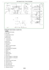
PowrQuad PowrQuad is a trademark of Deere & Company. Shift and Park Linkage Symptom/Cause Chart

PowrQuad PowrQuad is a trademark of Deere & Company. Shift and Park Linkage Adjustment

Shifter Cam Neutral Alignment

F-N-R Lower Linkage Inspection and Adjustment

F-N-R Upper Linkage Inspection and Adjustment

1-2-3-4 Speed Lower Linkage Inspection and Adjustment

1-2-3-4 Speed Upper Linkage Inspection and Adjustment

Park Rod Linkage Inspection and Adjustment

Range Shift Linkage Inspection and Adjustment

Shift and Park Linkage Final Checks and Adjustments

Remove Shift Control Assembly PowrQuad PowrQuad is a trademark of Deere & Company.

Disassemble Shift Control Assembly PowrQuad PowrQuad is a trademark of Deere & Company.

Recondition Upper Shift Linkage- PowrQuad PowrQuad is a trademark of Deere & Company.

Recondition Lower Shift Linkage- PowrQuad PowrQuad is a trademark of Deere & Company.

Range-Box-to-Shift Control Valve Housing Linkage- PowrQuad PowrQuad is a trademark of Deere & Company.

Repair Lower Park Lock Outer Linkage- PowrQuad PowrQuad is a trademark of Deere & Company.

Recondition Park Lock- PowrQuad PowrQuad is a trademark of Deere & Company.

Remove Shift Control Assembly- SyncroPlus SyncroPlus is a trademark of Deere & Company.

Disassemble Shift Control Assembly- SyncroPlus SyncroPlus is a trademark of Deere & Company.

Shifter Assembly-Exploded View- SyncroPlus SyncroPlus is a trademark of Deere & Company.

SyncroPlus SyncroPlus is a trademark of Deere & Company. Lower Shift Linkage

Recondition Lower Shift Linkage SyncroPlus SyncroPlus is a trademark of Deere & Company. W/O Creeper

Speed Select Shift Linkage Adjustment

Range Rod Adjustment

Repair Lower Park Lock Outer Linkage- SyncroPlus SyncroPlus is a trademark of Deere & Company.

Recondition Park Lock- SyncroPlus SyncroPlus is a trademark of Deere & Company.

Repair Lower Park Lock Inner Linkage

SyncroPlus SyncroPlus is a trademark of Deere & Company. Park Lock Linkage

Inspect and Adjust SyncroPlus SyncroPlus is a trademark of Deere & Company. Park Lock Linkage

Recondition Upper Shift Linkage- SyncroPlus SyncroPlus is a trademark of Deere & Company.

Creeper Control Lever

Lower Creeper Control Linkage-Exploded View

Electrical Controls and Sensors- PowrQuad PowrQuad is a trademark of Deere & Company.

Electrical Controls and Sensors- SyncroPlus SyncroPlus is a trademark of Deere & Company.

Group 10: SyncroPlus SyncroPlus is a trademark of Deere & Company. Transmission

Essential or Recommended Tools

Service Equipment and Tools

Other Material

Specifications

General Repair Procedures- SyncroPlus SyncroPlus is a trademark of Deere & Company. Transmission

Clutch Housing-Cross-Sectional View

Remove Clutch

Clutch Components-Exploded View

Disassemble Clutch

Assemble Clutch

Install Clutch

Remove Transmission Oil Pump

Transmission Oil Pump Components-Exploded View

Disassemble Transmission Oil Pump

Assemble Oil Pump

Install Transmission Oil Pump

Clutch Housing Valves

Remove Clutch Pedal Valve

Install Clutch Pedal Valve

Gear Transmission-Cross-Sectional View

Gear Transmission-Exploded View

Shifter Components-Exploded View

Disassemble Gear Transmission

Assemble Drive Shaft

Install Shafts

Adjust Shifting Mechanism

Final Assembly

Group 15: PowrQuad PowrQuad is a trademark of Deere & Company. Transmission

Essential or Recommended Tools

Service Equipment and Tools

Other Material

Specifications

General Repair Procedures- PowrQuad PowrQuad is a trademark of Deere & Company. Transmission

Transmission Components

Install Transmission in Repair Stand

Remove Transmission Front Cover/Front Valve Housing

Remove Front Valve Housing

Front Valve Housing Valves

Transmission Front Cover Valves

Diagnose Engine Malfunction

Replace Traction Clutch Valve Shifter Lever/Shaft Seal

Replace Traction Clutch Valve Inner Arm/Shaft

Transmission Pump-Cross-Sectional View

Repair Transmission Pump

Install Front Valve Housing

Install Transmission Front Cover/Front Valve Housing

Remove Shift Control Valve Housing

Replace Forward-Reverse/Speed Selector Shifter Levers/Shaft Seals

Replace Forward-Reverse/Speed Selector Shifter Shafts/Shifter Arms

Shift Control Valve Housing Valves

Modulator Valve-Cross-Sectional View

Planetary Housing Valves

Forward/Reverse Control Valve-Cross-Sectional View

Speed Selector Valve-Cross-Sectional View

Assemble and Install Shift Valve Housing

Disassemble Planetary/Reverse Brake Housing Assembly

Recondition Input Planetary Carrier

Input Planetary Assembly-Cross-Sectional View

Disassemble Reverse Brake Housing Components

Reverser Carrier/Traction Clutch Assembly-Cross-Sectional View

Recondition Reverser Carrier/Traction Clutch Assembly

Disassemble Planetary Housing Components

Direct Drive Clutch Assembly-Cross-Sectional View

Recondition Direct Drive Clutch Assembly

Assemble Planetary Housing Components

Assemble Reverse Brake Housing Components

Assemble Planetary/Reverse Brake Housing Assembly

Group 20: Creeper Transmission

Service Equipment And Tools

Other Material

Specifications

General Repair Procedures-Creeper Transmission

Recondition Creeper Transmission

Shifter Components-Cross-Sectional View

Remove and Install Shifter Components

Creeper Transmission-Cross-Sectional View

Remove Input/Output Drive Shaft Assembly

Disassemble and Assemble Drive Shaft/Snubber Brake

Remove and Install Countershaft

Install Input/Output Shaft Assembly

Group 25: Range Box

Essential or Recommended Tools

Service Equipment and Tools

Other Material

Specifications

General Repair Procedures-Range Box

30K and 40K Range Box

Remove and Disassemble Shifter Cover

Remove and Install Park Pawl

Reverse Interlock Shifter Shaft Components- PowrQuad PowrQuad is a trademark of Deere & Company.

Shifter Rails Interlock Components-Cross-Sectional View- PowrQuad PowrQuad is a trademark of Deere & Company. Range Box

Remove and Install Shifter Rails and Forks

Install and Adjust Shifter Forks and Rails

Assemble and Install Shifter Cover

Remove Differential Drive Shaft

Differential Drive Shaft-Cross-Sectional View

Determine Cone Point Shim Pack and Install Differential Drive Shaft

Input Shaft-Cross-Sectional View-30K Range Box

Input Shaft-Cross-Sectional View-40K Range Box

Remove and Disassemble Input Shaft

Assemble and Install Input Shaft

Adjust Input Shaft End Play

Section 56: Drive Systems

Group 00: Component Removal and Installation

Essential or Recommended Tools

Service Equipment and Tools

Other Material

Specifications

Sealing Instructions

Remove MFWD Clutch

Install MFWD Clutch

Remove MFWD Axle

Install MFWD Axle

Remove Rear PTO Assembly

Install Rear PTO Assembly

Remove Standard Final Drive

Install Standard Final Drive

Remove Hi-Crop Final Drive

Install Hi-Crop Final Drive

Group 05: Controls

Specifications

MFWD Switch

MFWD Solenoid

Differential Lock Switch

Differential Lock Solenoid

PTO Switch

PTO Clutch Solenoid

PTO Speed Sensor

Group 10: MFWD Clutch

Essential or Recommended Tools

Service Equipment and Tools

Specifications

General Repair Procedures-MFWD Clutch

MFWD Clutch-Cross-Sectional View

Disassemble MFWD Clutch

Disassemble MFWD Clutch Pack

Assemble MFWD Clutch Pack

Assemble MFWD Clutch

Group 15: MFWD Axle

Essential or Recommended Tools

Service Equipment and Tools

Other Material

Specifications

General Repair Procedures-MFWD Axle

Planetary Carrier, Wheel Hub, and Knuckle Spindle

Remove and Disassemble Planetary Carrier

Assemble and Install Planetary Carrier

Remove and Install Axle Housing

Remove and Disassemble Knuckle Spindle Assembly

Install Knuckle Spindle Assembly

Input Quill and Differential Drive Shaft

Remove and Disassemble Input Quill and Differential Drive Shaft

Determine Differential Drive Shaft Cone Point Shim Pack

Assemble and Install Differential Drive Shaft

Adjust Differential Drive Shaft End Play

Install Input Quill

Remove Differential

Differential Assembly-Cross-Sectional View

Disassemble Differential

Assemble Differential

Remove and Install Ring Gear

Install Differential

Adjust Differential Rolling Drag Torque

Adjust Differential Backlash

Replace Pivot Pin Bushing

Group 20: Rear Differential

Essential or Recommended Tools

Service Equipment and Tools

Specifications

General Repair Procedures-Rear Differential

Remove Differential

Rear Differential-Cross-Sectional View

Disassemble Rear Differential

Assemble Rear Differential

Adjust Differential Preload

Adjust Differential Backlash

Group 25: Final Drive

Essential or Recommended Tools

Service Equipment and Tools

Other Material

Specifications

General Repair Procedures-Final Drive

Final Drive-Cross-Sectional View Early Model 80 mm and All 86 mm Diameter Axle Shaft

Final Drive-Cross-Sectional View Later Model 80 mm Diameter Axle Shaft

Remove Planet Pinion Carrier

Disassemble Planet Pinion Carrier

Planet Pinion Carrier-Exploded View

Assemble Planet Pinion Carrier

Remove Axle Housing

Disassemble and Assemble Axle Housing

Disassemble and Assemble Axle Shaft

Axle Shaft Outer Bearing Diameter

Install Axle Housing

Install Planet Pinion Carrier and Check Rolling Drag Torque

Group 30: Hi-Crop Final Drive

Essential or Recommended Tools

Service Equipment and Tools

Other Material

Specifications

General Repair Procedures-Hi-Crop Final Drive

Hi-Crop Final Drive-Cross-Sectional View

Disassemble Final Drive

Assemble Final Drive

Group 35: PTO

Essential or Recommended Tools

Service Equipment and Tools

Specifications

General Repair Procedures-PTO

Clutch

Repair PTO

PTO Clutch-Cross-Sectional View

Remove and Disassemble PTO Clutch

Assemble and Install PTO Clutch

Remove and Disassemble Countershaft

PTO Countershaft-Cross-Sectional View

Assemble and Install

Two-Speed PTO Output Shaft-Cross-Sectional View

Shiftable PTO Output Shaft-Cross-Sectional View

Remove and Disassemble Output Shaft

Assemble and Install PTO Output Shaft

Shiftable PTO Shifter-Exploded View

Remove PTO Shifter

Install PTO Shifter

Replace PTO Brake

Replace PTO Output Shaft Oil Seal

Remove Valve Housing

Disassemble and Assemble Valve Housing

Install Valve Housing

Group 40: Drive Lines

Specifications

MFWD Drve Shaft

Engine Coupler Shaft

Group 45: Hydraulic Pump Drive

Essential or Recommended Tools

Service Equipment and Tools

Specifications

General Repair Procedures-Pump Drive

Hydraulic Pump Drive-Cross-Sectional View

Remove and Disassemble Pump Drive Pinion Gear

Remove and Disassemble Pump Drive Gear

Assemble and Install Pump Drive Gear

Assemble and Install Pump Drive Pinion

Section 60: Steering and Brakes

Group 05: Hydrostatic Steering

Essential or Recommended Tools

Service Equipment and Tools

Specifications

Remove and Install Steering Valve

Steering Valve-Exploded View

Disassemble, Inspect, and Assemble Steering Valve

Group 10: Steering Cylinders

Specifications

Service Parts Kits

Remove and Install Steering Cylinder

Cross-Sectional and Exploded View-Steering Cylinder

Group 15: Brake Valve

Service Parts Kits

Specifications

General Repair Procedures-Brake Valve

Remove and Install Brake Valve

Disassemble, Inspect, and Assemble Brake Valve

Bleed Brakes

Check Manual Brakes

Group 20: Brake Components

Specifications

Remove, Inspect, and Install Brake Pistons, Plates, and Disks

Inspect and Adjust Secondary Brake

Section 70: Hydraulics

Group 00: Component Removal and Installation

Essential or Recommended Tools

Specifications

Remove and Install Inlet-Priority Valve Assembly

Remove and Install Main Hydraulic Pump

Remove and Install Charge Pump

Group 05: Controls

Remove, Install, and Adjust SCV Linkage

Group 10: Hydraulic Pump and Charge Pump

Essential or Recommended Tools

Other Material

Service Parts Kits

Specifications

General Repair Procedures-Hydraulic Pumps

Remove and Install Hydraulic Pump Controller

Hydraulic Pump Controller-Exploded View

Disassemble, Inspect, and Assemble Pump Controller

Hydraulic Pump-Exploded View-25 cm 3 (1.5 in. 3)

Hydraulic Pump-Exploded View-40 cm 3 (2.4 in. 3)

Disassemble, Inspect, and Assemble Hydraulic Pump

Adjust Yoke Bearing Preload

Adjust Shaft Bearing Preload 40 cm 3 (2.4 in. 3) Pump

Inspect Hydraulic Charge Pump

Group 15: Hydraulic System Valves

Essential or Recommended Tools

Service Parts Kits

Specifications

General Repair Procedures-Hitch and Inlet-Priority Valves, and Filter Bypass

Remove, Inspect, and Install Hydraulic Filter Bypass

Disassemble, Inspect, and Assemble Inlet-Priority Valve

Remove and Install Hitch Valve

Disassemble, Inspect, and Assemble Hitch Valve

Adjust Hitch Valve

Group 20: Selective Control Valves and Couplers

Essential or Recommended Tools

Other Material

Service Parts Kits

Specifications

General Repair Procedures-Selective Control Valves and Couplers

SCV Identification

Remove, Inspect, and Install Selective Control Valves

Selective Control Valve-Exploded View-Three-Position

Selective Control Valve-Exploded View-Two-Position

Selective Control Valve-Exploded View-Single-Position

Replace Control Knobs

Inspect Poppet Load-Check Valves

Inspect Pressure Compensator Valve-Three-Position SCV

Inspect Metering Valve- Three-Position SCV

Inspect Metering Valve- Two-Position SCV

Disassemble, Inspect, and Assemble Control Valve- Three-Position SCV

Disassemble, Inspect, and Assemble Control Valve-Two-Position SCV

Disassemble, Inspect, and Assemble Control Valve-Single-Position SCV

Disassemble, Inspect, and Assemble Couplers

Group 25: Hitch

Essential or Recommended Tools

Specifications

Remove and Install Lift Cylinders

Cross-Sectional and Exploded View-Lift Cylinder

Replace Rockshaft Housing Bushings

Group 30: Row Guidance

Service Parts Kits

Specifications

Remove and Install Probe Module

Repair Row Guidance Cylinder

Exploded View-Row Guidance Cylinder

Group 35: Remote Cylinder

Specifications

Disassemble and Inspect Remote Cylinder

Assemble and Bleed Remote Cylinder

Group 40: Bleed Hydraulic System

Bleed Hydraulic System

Section 80: Miscellaneous

Group 00: Component Removal and Installation

Special or Essential Tools

Specifications

Remove Front Axle

Install Front Axle

Group 05: Front Axle

Other Material

Specifications

Replace Knee Bushings

Replace Knee Bushings

Group 10: Hood

Adjust Hood

Section 90: Operator Station

Group 00: Component Removal and Installation

Specifications

Remove Cab

Install Cab

Group 05: Controls

Remove and Install Heater and Air Flow Control Cables

Adjust Heater and Air Flow Control Cables

Group 10: Air Conditioning System

Special or Essential Tools

Service Equipment and Tools

Other Material

Service Parts Kits

Hose and Tubing O-Ring Connection Torques

Specifications

Discharge Air Conditioning System

Remove and Install Compressor

Test Volumetric Efficiency

Test Shaft Seal Leakage

Disassemble and Assemble Compressor Clutch

Check Clutch Hub Clearance

Inspect Compressor Manifold

Disassemble, Inspect, and Assemble Compressor

Remove and Install Compressor Relief Valve

Replace Receiver-Dryer

Remove Evaporator/Heater Core

Leak Test Evaporator/Heater Core

Install Evaporator/Heater Core

Service Expansion Valve

Expansion Valve Bench Test-Diagram

Expansion Valve Bench Test

Replace Thermo Switch

Remove, Clean, and Install Air Filters

Refrigerant Oil Information

Check Refrigerant Oil Charge

Determine Correct Refrigerant Oil Charge

Add Refrigerant Oil To System

System Information

Air Conditioning System-Diagram

Air Conditioning System Fitting-Reference Chart

Flush Air Conditioning System

Purge Air Conditioning System

Evacuate Air Conditioning System

Charge Air Conditioning System

Group 15: Heating System

Remove Heater Control Valve

Leak Test Heater Control Valve

Install Heater Control Valve

Group 20: Seat

Other Material

Remove Seat and Mechanical Suspension

Disassemble, Inspect, and Assemble Mechanical Suspension Assembly

Install Mechanical Suspension Assembly

Remove Seat and Air Suspension

Remove Seat From Suspension

Remove Swivel Plate

Disassemble, Inspect, and Assemble Air Suspension Assembly

Install Seat and Air Suspension

Group 25: ROPS and Cab

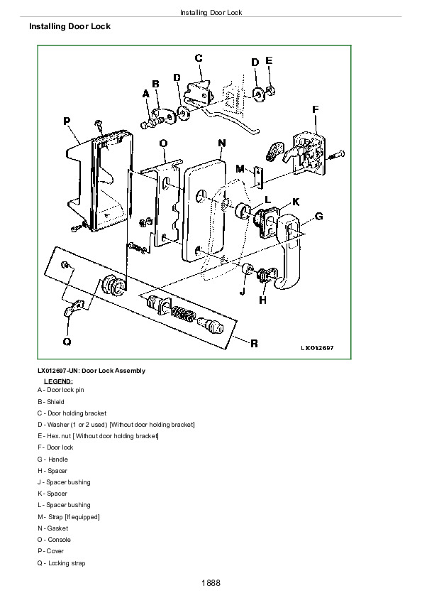
Repair Cab Door Latch

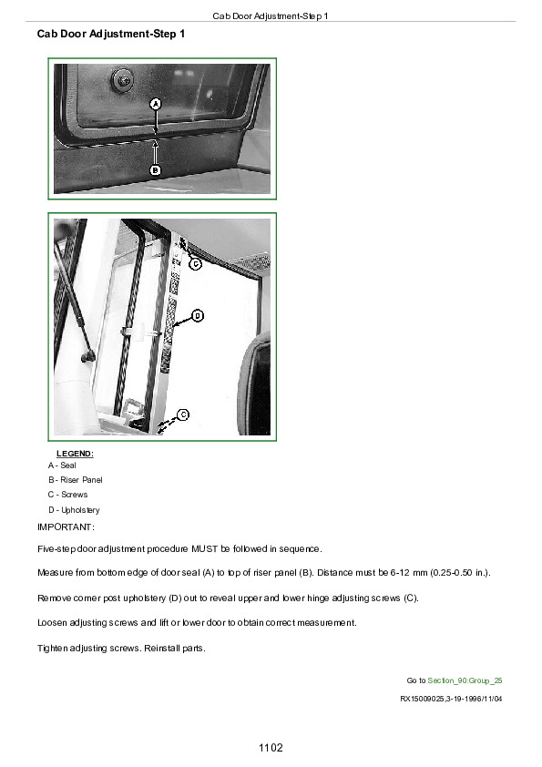
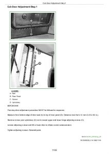
Cab Door Adjustment-Step 1

Cab Door Adjustment-Step 2

Cab Door Adjustment-Step 3

Cab Door Adjustment-Step 4

Cab Door Adjustment-Step 5

Check ROPS

Section 99: Dealer Fabricated Tools

Group 05: Fabricated Tools

Fabricated Tools

DFRW4-AXLE WHEEL HUB TOOL

DFRW11-Differential Side Bevel Gear End Play Tool

DFRW20-Compressor Holding Fixture

DFRW29-Final Drive Housing Adapter

DFRW30-Axle Jacking Tool

DFRW60 – DFRW61 – DFRW62-Extension Harnesses

DFRW63 – DFRW64 – DFRW65 – DFRW66 – DFRW81-Tap-Out Harnesses

DFRW70-Holding Tool

DFRW77-Rear Tractor Access Platform

DFRW78-Seat Support Tray

DFRW79-Piston Holding Tool

DFRW80-Front PTO Lifting Brackets and Spacers

DFRW108-Park Rod Adjusting Nut Tool {para}Tool may be purchased. Order JDG952

John Deere Tractors 7200, 7400 Repair Service Manual (TM1551)


INSTANT DOWNLOAD


Posted on

John Deere Tractors 6800, 6900 Repair Technical Manual (TM4516)


INSTANT DOWNLOAD


Complete Repair Service Technical Manual for John Deere Tractors 6800 and 6900, with all the workshop information to maintain, repair, and rebuild like professional mechanics.

John Deere Tractors 6800 and 6900 series workshop technical manual (repair) includes:
* Numbered table of contents easy to use so that you can find the information you need fast.
* Detailed sub-steps expand on repair procedure information
* Numbered instructions guide you through every repair procedure step by step.
* Notes, cautions and warnings throughout each chapter pinpoint critical information.
* Bold figure number help you quickly match illustrations with instructions.
* Detailed illustrations, drawings and photos guide you through every procedure.
* Enlarged inset helps you identify and examine parts in detail.

TM4516 English – John Deere Tractors 6800, 6900 Technical Manual (Repair).pdf
tm4517 German – Traktoren 6800 und 6900
tm4518 French – Tracteurs 6800 et 6900

Total Pages: 1,073pages
File Format: PDF (bookmarked, ToC, Searchable, Printable, high quality)
Language: English …

MAIN SECTIONS
   Foreword
   Safety
      Safety Measures
   General Information
      Specifications
      Tune-Up
      Predelivery Inspection
   Engine
      Engine Removal and Installation
   Fuel, Air Intake and Cooling Systems
      Speed Control Linkage
      Fuel System
      Air Intake System
      Cooling System
      Cold Weather Starting Aids
   Electrical System
      Connectors
      Wiring Harnesses
      Charging Circuit
      Starting Motor Circuit
      Switches, Relays and Solenoids
      Monitoring System
      Auxiliary Lighting and Electrical Components
      Convenience and Accessory Components
   PowrQuad™ Transmission
      Removal and Installation of Transmission Components
      Transmission Controls
      PowrQuad™ Module
      Creeper Transmission
      Range Transmission
   Drive Systems
      Component Removal and Installation
      U-Jointed Shafts and Torsion Damper
      Front Wheel Drive Clutch
      Differential
      Final Drives
      Rear PTO
      Front PTO
      Hydraulic Pump Drive
      Front Implement Drive
   Steering and Brakes
      Hydrostatic Steering
      Brake Valve
      Rear Wheel Brakes
      Handbrake
      Hydraulic Trailer Brake
      Air Brakes
   Hydraulic System
      Controls
      Hydraulic Pump and Charge Pump
      Valves
      Three-Point Hitch
      Selective Control Valves and Couplers
   Miscellaneous
      Component Removal and Installation
      Main Frame
      Front and Rear Wheels
      Trailer Hitch
      Pick-Up Hitch
      Swinging Drawbar
   Operator’s Cab and 4-Post Rops
      Tilting or Removing/Installing Operator’s Cab
      Controls and Instruments
      Electronic Hitch Control Components
      Air Conditioning System
      Heating System
      Operator’ Cab
      Seats
      Radio Installation
   Special Tools (Dealer-Fabricated)

tm4516 – 6800 and 6900 tractors

Table of Contents

Foreword

Section 05: Safety

Group 05: Safety Measures

Safety Information

“Important” – Information

“Note” – Information

Handle Fluids Safely-Avoid Fires

Prevent Battery Explosions

Prepare for Emergencies

Prevent Acid Burns

Avoid High-Pressure Fluids

Park Machine Safely

Support Machine Properly

Wear Protective Clothing

Work in Clean Area

Service Machines Safely

Work In Ventilated Area

Illuminate Work Area Safely

Replace Safety Signs

Use Proper Lifting Equipment

Avoid Heating Near Pressurized Fluid Lines

Remove Paint Before Welding or Heating

Keep ROPS Installed Properly

Service Tires Safely

Practice Safe Maintenance

Use Proper Tools

Dispose of Waste Properly

Live With Safety

Service Front-Wheel Drive Tractor Safely

Section 10: General Information

Group 05: Specifications

Specifications

Diesel Engine Oil

Transmission and Hydraulic Oil

Front Wheel Drive Axle Oil

Engine Coolant

Grease

Oil Filters

Mixing of Lubricants

Alternative and Synthetic Lubricants

Lubricant Storage

Unified Inch Bolt and Cap Screw Torque Values

Metric Bolt and Cap Screw Torque Values

Serial Number Plates

Product Identification Number and Component Serial Numbers

Group 10: Tune-Up

Specifications

Preliminary Engine Test

Tractor Tune-Up

Final Engine Check

Tractor Operation Check

Group 15: Predelivery Inspection

Predelivery Inspection

Section 20: Engine

Group 00: Engine Removal and Installation

Special or Essential Tools

Specifications

Removing Engine

Installing Engine

Replacing Engine Mountings

Front Engine Mountings

Rear Engine Mountings

Section 30: Fuel, Air Intake and Cooling Systems

Group 05: Speed Control Linkage

Specifications

Adjusting Throttle Hand Lever and Pedal

Adjusting Speed Control Linkage

Group 10: Fuel System

General Information

Removing Fuel Tank

Installing Fuel Tank

Replacing Fuel Gauge Sending Unit

Replacing Fuel Transfer Pump

Bleeding Fuel System

Changing Fuel Filter

Group 15: Air Intake System

General Information

Air Intake System

Group 20: Cooling System

General Information

Specifications

Removing Radiator

Replacing Fan and Viscous Fan Drive

Installing Radiator

Relieving Drive Belt

Replacing Drive Belt

Replacing Drive Belt Tensioner

Repairing Drive Belt Tensioning Device

Hydraulic Drive Belt Tensioner Up to tractor serial no. 159438 – Exploded View

Group 25: Cold Weather Starting Aids

Fuel Preheater

Electric Starting Aid

Coolant Heater

Section 40: Electrical System

Group 05: Connectors

Special or Essential Tools

Disconnecting Electrical Circuit

METRI PACK Connector

WEATHER PACKWEATHER PACK is a trademark of Packard Electric. Connector

CRIMP SNAP IN Connector

CPCCPC is a trademark of AMP Inc. Connector

Replace Load Center Connector

Replace Power Distribution Center Connectors

Replacing Female Terminal on 45-Pin Plug

Installing Terminal

Changing Terminals

Stripping Wire Ends

Installing Terminal

Group 10: Wiring Harnesses

Ground Point Locations

Removing and Installing Engine Wiring Harness

Removing and Installing Cab Wiring Harness

Removing and Installing Wiper and Air Conditioning Harness

Removing and Installing Cab Roof Wiring Harness

Removing and Installing Transmission Wiring Harness

Group 15: Charging Circuit

Repair Alternator-Use CTM

General

Specifications

Removing Alternator

Relieving Drive Belt

Group 20: Starting Motor Circuit

Special or Essential Tools

Specifications

Repair Starter-Use CTM

Removing Starting Motor

Group 25: Switches, Relays and Solenoids

Disconnecting Electrical Circuit

Specifications

Replace Stop Light Switches

Adjusting the Stop Light Switch

Removing and Installing the Thermostat Switch

Removing and and Installing the High/Low Pressure Switch

Replacing Blower Switch

Replacing Air Conditioning Switch

Removing HMS (Headland Management System) Switch

Replace MFWD Solenoid

Replace MFWD Switch

Replace Differential Lock and Rear PTO Solenoids

Differential Lock Switch

Replace PTO Switch

Replace Load/Depth Controller

Replace Hitch Control Potentiometer and Switch

Replacing Draft Sensor

Replacing Rockshaft Remote Control Switch

Replace and Install Hitch Position Sensor

Location of Hitch Position Sensor

Replace Fuel Shut-Off Solenoid

Replace Main Switch

Replace Light Switch and Hazard Warning Light Switch

Replace Wiper/Washer Switch

Main Fuses

Fuse Box (Load Center) 1 (Up to Serial No. 139832)

Fuse Box (Load Center) 2 (Up to Serial No. 139832)

Fuse Box (Load Center) 1 (From Serial No. 139833)

Fuse Box (Load Center) 2 (From Serial No. 139833)

Group 30: Monitoring System

Disconnecting Electrical Circuit

Replacing PTO Speed Sending Unit

Replacing Engine Oil Pressure Sending Unit

Replacing Engine Speed Sending Unit

Replacing Air Cleaner Sending Unit

Replacing Coolant Temperature Sending Unit

Replacing Fuel Gauge Sending Unit

Replace Speed Sending Unit

Replacing Overvoltage Protection

Temperature and Pressure Sending Units in Transmission Oil Circuit

Removing Instrument Unit

Group 40: Auxiliary Lighting and Electrical Components

Replace Seven-Terminal Outlet Socket

Group 45: Convenience and Accessory Components

Disconnecting Electrical Circuit

Removing and Installing Fan and Radiator

Replace Wiper Motor

Replace Dome Light Switch

Section 55: Transmission

Group 00: Removal and Installation of Transmission Components

Special Or Essential Tools

Specifications

Removing the PowrQuad PowrQuad is a trademark of Deere & Company. Module

Installing the PowrQuad PowrQuad is a trademark of Deere & Company. Module

Removing the Creeper Transmission

Installing Creeper Transmission

Removing the Range Transmission

Installing the Range Transmission

Group 05: Transmission Controls

Specifications

Gear Shift Linkage

Range Shift Linkage

Installing Bowden Cables

Adjusting Reverser Drive Linkage

Adjusting Shift Linkage

Adjusting Parking Lock

Group 10: PowrQuadPowrQuad is a trademark of Deere & Company. Module

Special or Essential Tools

Service Equipment and Tools

Other Material

Specifications

Repair Instructions

Transmission Components

Install Transmission in Repair Stand

Remove Transmission Front Cover/Front Valve Housing

Remove Front Valve Housing

Front Valve Housing Valves

Transmission Front Cover Valves

Traction Clutch Valve

Replace Traction Clutch Valve Shifter Lever/Shaft Seal

Replace Traction Clutch Valve Inner Arm/Shaft

Transmission Pump-Cross-Sectional View

Repair Transmission Pump

Install Front Valve Housing

Install Transmission Front Cover/Front Valve Housing

Remove Shift Control Valve Housing

Replace Forward-Reverse/Speed Selector Shifter Levers/Shaft Seals

Replace Forward-Reverse/Speed Selector Shifter Shafts/Shifter Arms

Shift Control Valve Housing Valves

Modulator Valve-Cross-Sectional View

Planetary Housing Valves

Forward/Reverse Control Valve-Cross-Sectional View

Speed Selector Valve-Cross-Sectional View

Assemble and Install Shift Valve Housing

Disassemble Planetary/Reverse Brake Housing Assembly

Recondition Input Planetary Carrier

Input Planetary Assembly-Cross-Sectional View

Disassemble Reverse Brake Housing Components

Reverser Carrier/Traction Clutch Assembly-Cross-Sectional View

Recondition Reverser Carrier/Traction Clutch Assembly

Disassemble Planetary Housing Components

Direct Drive Clutch Assembly-Cross-Sectional View

Recondition Direct Drive Clutch Assembly

Assemble Planetary Housing Components

Assemble Reverse Brake Housing Components

Assemble Planetary/Reverse Brake Housing Assembly

Group 15: Creeper Transmission

Service Equipment and Tools

Specifications

Preliminary Work

Creeper Transmission-Cross-Sectional View

Shifter Components-Cross-Sectional View

Removing Shifter Components

Input/Output Drive Shaft – Components

Countershaft and Housing – Components

Remove Input/Output Drive Shaft Assembly

Disassemble and Assemble Drive Shaft/Snubber Brake

Remove and Install Countershaft

Install Input/Output Shaft Assembly

Final Assembly

Group 20: Range Transmission

Special or Essential Tools

Service Equipment and Tools

Specifications

Repair Instructions

Preliminary Work

Range Box Up to Transmission Serial No. 024698 corresponding tractor serial no. is 135080

Range Box From Transmission Serial No. 024699 corresponding tractor serial no. is 135081

Shifting Mechanism – Cross-Sectional View

Removing Differential Drive Shaft

Removing Drive Shaft

Differential Drive Shaft – Exploded View

Drive Shaft (30 KM/H; 18.5 MPH Version) – Exploded View

Drive Shaft (40 KM/H; 25 MPH Version) – Exploded View

Shifting Mechanism – Exploded View

Parking Lock – Exploded View

Repairing Drive Shaft

Installing Drive Shaft

Adjusting Drive Shaft End Play

Installing Differential Drive Shaft and Adjusting Cone Point

Adjusting End Play of Differential Drive Shaft

Adjusting Shifting Mechanism

Repairing and Installing Shift Cover

Final Assembly

Section 56: Drive Systems

Group 00: Component Removal and Installation

Special or Essential Tools

Specifications

Removing Differential Housing

Installing Differential Housing

Removing PTO Housing

Installing PTO Housing

Removing Final Drives

Installing Final Drives

Removing Front Wheel Drive Clutch

Installing Front-Wheel Drive Clutch

Removing Front PTO

Installing Front PTO

Group 05: U-Jointed Shafts and Torsion Damper

Specifications

Removing U.J. Shaft (FWD)

Installing U.J. Shaft (FWD)

Removing U.J. Shaft (Engine)

Removing the Torsion Damper

Changing the Torsion Damper Bearing

Installing the Torsion Damper

Installing the U.J. Shaft (Engine)

Disassemble Universal Jointed Drive Shaft

Assembling Jointed Shaft

Group 10: Front Wheel Drive Clutch

Special or Essential Tools

Service Equipment and Tools

Specifications

Repair Instructions

Preliminary Work

Front Wheel Drive Clutch – Cross Sectional View

Removing Clutch

Disassemble MFWD Clutch

Front Wheel Drive Clutch Components

Assembling Clutch

Installing Clutch

Adjusting End Play

Adjusting the Brake Band

Final Assembly

Group 15: Differential

Special or Essential Tools

Service Equipment and Tools

Specifications

Repair Instructions

Preliminary Work

Removing the Differential

Disassembling the Differential

Exploded View

Assembling the Differential

Installing the Differential

Adjusting Differential Preload

Adjusting Backlash

Final Assembly

Group 20: Final Drives

Special or Essential Tools

Service Equipment and Tools

Other Material

Specifications

Repair Instructions

Preliminary Work

Final Drive-Cross-Sectional View

Disassemble Planet Pinion Carrier

Planet Pinion Carrier-Exploded View

Assemble Planet Pinion Carrier

Remove Axle Housing

Disassemble and Assemble Axle Housing

Disassemble and Assemble Axle Shaft

Install Axle Housing

Install Planet Pinion Carrier and Check Rolling Drag Torque

Final Assembly

Group 25: Rear PTO

Special or Essential Tools

Service Equipment and Tools

Specifications

Repair Instructions

Repair PTO

PTO Clutch-Cross-Sectional View

Remove and Disassemble PTO Clutch

Assemble and Install PTO Clutch

Remove and Disassemble Countershaft

PTO Countershaft-Cross-Sectional View

Assemble and Install

Shiftable PTO Output Shaft-Cross-Sectional View

Remove and Disassemble Output Shaft

Assemble and Install PTO Output Shaft

Shiftable PTO Shifter – Exploded View

Remove PTO Shifter

Install PTO Shifter

Replace PTO Brake

Replacing Oil Seal on PTO Output Shaft

Remove Valve Housing

Disassemble and Assemble Valve Housing

Install Valve Housing

PTO Shifting Parts

Changing and Adjusting the Bowden Cable

Adjusting the Indicator Light Switch

Group 30: Front PTO

Special or Essential Tools

Specifications

Front PTO (Running Clockwise)

Front PTO (Running Counterclockwise)

Front PTO – Sectional View

Removing Front PTO Shaft

Disassembling Front PTO Shaft

PTO (Clockwise Running) – Exploded View

PTO (Counterclockwise Running) – Exploded View

PTO Clutch and Brake – Clockwise Running PTO

PTO Clutch and Brake – Counterclockwise Running PTO

Front PTO Housing

Assembling Front PTO

Determining Preload of Input Shaft and PTO Shaft Taper Roller Bearings

Installing Front PTO Shaft

Repairing Solenoid Valve

Layout of Oil Lines

Group 35: Hydraulic Pump Drive

Special or Essential Tools

Service Equipment and Tools

Specifications

Hydraulic Pump Drive-Cross-Sectional View

Remove and Disassemble Pump Drive Pinion Gear

Remove and Disassemble Pump Drive Gear

Assemble and Install Pump Drive Gear

Assemble and Install Pump Drive Pinion

Group 40: Front Implement Drive

Special or Essential Tools

Specifications

Exploded View

Replacing Damper

Section 60: Steering and Brakes

Group 05: Hydrostatic Steering

Special or Essential Tools

Specifications

Removing Steering Valve

Removing Steering Column and Steering Valve

Steering Valve- Exploded View

Repairing Steering Valve

Disassembling the Steering Valve

Exploded View of Steering Valve

Assembling the Steering Valve

Adjusting Double-Acting Shock Valves

Steering Wheel and Steering Column

Repairing the Steering Column

Installing Steering Valve

Installing Steering Column and Steering Valve

Group 10: Brake Valve

Specifications

Repair Instructions

Removing Brake Valve

Repair Brake Valve

Installing Brake Valve

Adjusting the Stop Light Switch

Group 15: Rear Wheel Brakes

Specifications

Preliminary Work

Removing the Rear Wheel Brakes

Rear Wheel Brakes – Exploded View

Repairing the Brakes

Installing the Rear Brakes

Final Assembly

Bleeding the Brakes

Checking the Brakes

Group 20: Handbrake

Specifications

Preliminary Work

Removing the Handbrake

Exploded View of Handbrake – 6800 Tractor

Exploded View of Handbrake – 6900 Tractor

Installing the Handbrake

Adjusting the Brake Band

Final Assembly

Handbrake Components

Replacing the Handbrake Cable

Adjusting the Handbrake

Group 25: Hydraulic Trailer Brake

Special or Essential Tools

Specifications

Replacing Trailer Brake Valve

Replacing the Check Valve

Bleeding Trailer Brake Valve

Checking Trailer Brake Valve

Cleaning Trailer Brake Valve

Cleaning Sieve

Group 30: Air Brakes

Special or Essential Tools

Specifications

General Information

Installing the Screw Unions

Changing the Compressor

Changing the Compressed Air Tank

Changing the Pressure Control Valve

Changing the Pressure-Limiting Valve

Changing the Trailer Control Valve

Changing the Pressure Gauge

Changing the Coupling Ends

Visual and Operational Checks

Leak Test

Checking the Handbrake (Dual-Line Brakes)

Checking the Handbrake (Single-Line Brakes)

Adjusting the Handbrake

Checking the “Supply” Coupling End

Section 70: Hydraulic System

Group 05: Controls

General Information

Connecting Bowden Cable

SCV Actuating Elements

Adjusting Bowden Cable

Installing Multi-Function Lever

Adjusting Multi-Function Lever

Group 10: Hydraulic Pump and Charge Pump

Service Equipment and Tools

Other Material

Specifications

Repair Instructions

Removing Charge Pump

Disassembling Charge Pump

Assembling Charge Pump

Installing Charge Pump

Checking Lube Oil Valve

Restrictor in Oil Tank

Check Valve in Oil Leak-Off Line

Changing the Hydraulic Pump Controller

Hydraulic Pump Controller-Exploded View

Disassemble, Inspect, and Assemble Hydraulic Controller

Adjusting the Controller

Removing the Hydraulic Pump

Installing the Hydraulic Pump

Hydraulic Pump 40 cm3 (2.4 cu.in) – Exploded View

Hydraulic Pump 25 cm3 (1.5 cu.in) – Exploded View

Disassemble, Inspect and Assemble Hydraulic Pump

Adjust Swashplate Bearing Preload

Adjust Shaft Bearing Preload-40 cm 3 (2.4 cu.in) Pump

Group 15: Valves

Special or Essential Tools

Special Tools (Dealer Fabricated)

Specifications

Repair Instructions

Direct Control of Rockshaft

Removing the Rockshaft Valve

Repairing Rockshaft Valve

Depth to Which Pressure and Discharge Valves are Screwed In

Changing the Stepper Motor

Centering the Stepper Motor

Installing the Rockshaft Valve

Installing Shuttle Valves

Repairing the Inlet Priority Valve – Exploded View

Removing the Inlet Priority Valve

Installing the Inlet Priority Valve

Checking Oil Filter Head

Filter Relief Valve

Power Beyond Application Valve – Exploded View (New Version)

Power Beyond Application Valve – Exploded View (Old Version)

Connecting the Power Beyond Application Valve

Adjusting the Power Beyond Application Valve

Converting the Power Beyond Application Valve

Connecting the Power Beyond Application Valve

Adjusting the Power Beyond Application Valve

Group 20: Three-Point Hitch

Other Material

Specifications

Changing the Position Sensor

Draft Sensor and Draft Link Support – Exploded View

Changing the Draft Sensor and Draft Link Support

Removing and Installing the Lift Cylinders

Cross-Section and Exploded View – Lift Cylinder

Replacing the Bushings on the Rockshaft Housing

Automatic Stabilizer Rod (Left-Hand)

Adjustable Stabilizer Rod (Left or Right)

Adjustable Stabilizer Rod (Right-Hand)

Group 25: Selective Control Valves and Couplers

Special Tools (Dealer Fabricated)

Other Material

Specifications

Repair Instructions

SCV Identification

Removing Selective Control Valves

Series 100 Selective Control Valve – Exploded View

Disassemble, Inspect and Assemble the Control Valve-Series 100

Series 200 Selective Control Valve-Exploded View

Series 300 Selective Control Valve-Exploded View

Replace Control Knobs

Inspect Poppet Load-Check Valves

Inspect Pressure Compensator Valve-300 Series

Inspect Metering Valve-Three-Position SCV

Inspect Metering Valve-200 Series

Disassemble, Inspect, and Assemble Control Valve-300 Series

Disassemble, Inspect, and Assemble Control Valve-200 Series

Installing Selective Control Valves

Installing Shuttle Valves

Installing the Endplate

Adjustment of Pressure Limit at Selective Control Valves (300 Series)

Changing Couplers

Deluxe Coupler – Exploded View

Repairing the Deluxe Coupler

Checking Couplers for Leaks

Section 80: Miscellaneous

Group 00: Component Removal and Installation

Special or Essential Tools

Specifications

Removing Main Frame Halves

Installing Main Frame Halves

Removing Front Wheel Drive Axle

Installing Front Wheel Drive Axle

Removing Front Axle Support

Installing Front Axle Support

Group 05: Main Frame

Specifications

Removing and Installing the Main Frame

Group 10: Front and Rear Wheels

Special or Essential Tools

Specifications

Removing a Wheel (Front or Rear)

Attaching the Front Wheels

Attaching the Rear Wheels

Group 15: Trailer Hitch

Specifications

Installing the Trailer Mounting

Installing the Guide Rails

Trailer Mounting (Height-Adjustable, 4-Position)

Trailer Mounting (Height-Adjustable, 9-Position)

Repairing the Automatic Trailer Hitch

Remote Control for Automatic Trailer Hitch

Adjusting the Remote Control

Functional Check

Group 20: Pick-Up Hitch

Specifications

Installing Upper Frame

Frame Assembly – Exploded View

Operating Lever and Lift Links – Exploded View

Hydraulic Parts

Repairing Hydraulic Cylinder

Adjusting Lift Links

Adjusting Guide Stop

Changing the Bowden Cable

Adjusting the Bowden Cable

Operational Check

Group 25: Swinging Drawbar

Torques for Hardware – Swinging Drawbar

Torques for Hardware – Swinging Drawbar with Pick-Up Trailer Hitch

Section 90: Operator’s Cab and 4-Post Rops

Group 00: Tilting or Removing/Installing Operator’s Cab

Special or Essential Tools

Specifications

Tilting the Cab Upward

Tilting the Cab Downward

Removing the Operator’s Cab

Installing Operator’s Cab

Group 05: Controls and Instruments

Disconnecting Electrical Circuit

Specifications

Removing Instrument Unit

Replacing Bulbs

Removing the Control Panel

Replacing a Bulb

Adjusting Digital Control

Adjusting Analog Control

Removing Multi-Function Unit

Replacing Multi-Function Unit Components

Installing Steering Wheel

Replacing Basic Control Module

Group 10: Electronic Hitch Control Components

Disconnecting Electrical Circuit

Replacing Electronic Control Unit

Activating Quick-Lower or Hitch Dampening Functions

Replacing Operation Unit

Group 15: Air Conditioning System

Special or Essential Tools

Specifications

Safety at Work

Handling Refrigerant

In an Emergency

Safety Equipment

Storage of Refrigerant Containers

R134A Refrigerant

Discharging the System

Evacuating the System

Filling With Refrigerant Oil

Filling the System

Topping Up a Partly Discharged System

Leak Test

Removing the Compressor

Checking Level in the Compressor

Disassembling the Compressor Clutch

Checking Clutch Hub Clearance

Checking the Compressor Manifold

Installing the Compressor

Removing and Installing the Condenser

Removing and Installing the Receiver-Drier

Removing and Installing the Evaporator and Expansion Valve

Installing Condensation Water Drain Hoses

Removing and Installing the Thermostat Switch

Removing and and Installing the High/Low Pressure Switch

Group 20: Heating System

Ventilator and Heater, Exploded View

Removing and Installing Fan and Radiator

Removing and Installing Heating Regulator

Removing the Air Filter

Group 25: Operator’ Cab

Specifications

Removing Cab Frame

Removing and Installing Mounting Brackets

Installing Windshield

Installing Rear Window

Adjusting Window Contact Pressure

Removing Cab Door

Installing Cab Door

Installing Door Lock

Installing Door Holding Bracket

Replacing Handrail or Rear View Mirror

Removing Hatch

Removing Outer Roof

Removing Inner Roof

Installing Inner Roof

Group 30: Seats

Specifications

Comfort Seat DS44-07, Exploded View

Comfort Seat DS44-06, Exploded View

Super Comfort Seat S85/90-05, Exploded View – Upper Section

Super Comfort Seat DS85H1-02, Exploded View – Lower Section

Air Comfort Seat MSG95A-00, Lower Section

Passenger Seat, Exploded View

Group 35: Radio Installation

Radio, Loudspeakers and Aerial, Exploded View

Section 99: Special Tools (Dealer-Fabricated)

Group 05: Special Tools (Dealer-Fabricated)

DFRW29-Final Drive Housing Adapter

DFRW30-Axle Jacking Tool

DFRW79-Piston Holding Tool

Holding Device

Shifter Rail Detent Holding Tool

Socket Wrench Insert

Suspension Eyes for Operator’s Cab

John Deere Tractors 6800, 6900 Repair Technical Manual (TM4516)


INSTANT DOWNLOAD


Posted on

John Deere Tractors 6100, SE6100, 6200, SE6200, 6300, SE6300, 6400, SE6400, 6506, 6600 Repair Technical Manual (TM4493)


INSTANT DOWNLOAD


Complete Repair Service Technical Manual for John Deere Tractors 6100, SE6100, 6200, SE6200, 6300, SE6300, 6400, SE6400, 6506, 6600, with workshop information to maintain, repair, and service like professional mechanics.

John Deere 2WD or MFWD Tractors 6100, 6200, 6300, 6400, 6506, 6600, SE6100, SE6200, SE6300 workshop technical manual (repair) includes:
* Numbered table of contents easy to use so that you can find the information you need fast.
* Detailed sub-steps expand on repair procedure information
* Numbered instructions guide you through every repair procedure step by step.
* Notes, cautions and warnings throughout each chapter pinpoint critical information.
* Bold figure number help you quickly match illustrations with instructions.
* Detailed illustrations, drawings and photos guide you through every procedure.
* Enlarged inset helps you identify and examine parts in detail.

TM4493 English – John Deere Tractors 6100, 6200, 6300 6400, 6506, 6600 and SE Models  Repair Technical Manual
tm4485 German – Traktoren 6100 bis 6600 und SE
tm4494 French – Tracteurs 6100 – 6600 et tracteurs SE
tm4499 Italian – Trattori 6100, 6200, 6300 6400, 6506 e 6600
tm4500 Swedish – 6100 till 6600 Traktorer och Se-traktorer Reparation

Total Pages: 1,932 pages
File Format: PDF (bookmarked, ToC, Searchable, Printable)
Language: English

MAIN SECTIONS
Foreword
   Safety
      Safety Measures
   General Information
      Specifications
      Tune-Up
      Predelivery Inspection
   Engine
      Engine Removal and Installation
   Fuel, Air Intake, Cooling and Exhaust Systems
      Speed Control Linkage
      Fuel System
      Air Intake System
      Cooling System
      Cold Weather Starting Aids
      Exhaust System
   Electrical System
      Connectors
      Wiring Harnesses
      Charging Circuit
      Starting Motor Circuit
      Switches, Relays and Solenoids
      Monitoring System
      Auxiliary Lighting and Electrical Components
      Convenience and Accessory Components
   SyncroPlus™ Transmission
      Removal and Installation of Transmission Components
      Summary of Important Specifications
      Transmission Shift Controls
      PERMA-CLUTCH 2™
      Gear Transmission
      Creeper Transmission
      Option Transmission
      Range Transmission
   PowrReverserPowrRever™
      Removal and Installation of PowrReverser PowrRever™ Module
      Transmission Shift Controls
      PowrReverserPowrRever™ Module
      Gear Transmission
   PowrQuad™ Transmission
      Removal and Installation of PowrQuad™ Module
      Transmission Shift Controls
      PowrQuad™ Module
   Drive Systems
      Component Removal and Installation
      U-Jointed Shafts and Torsion Damper
      Front Wheel Drive Clutch Up to Transmission Serial No. 114447
      Front Wheel Drive Clutch, Transm. Serial No. 114448 to 161066
      Front Wheel Drive Clutch from Transmission Serial No. 161067
      Differential
      Hydraulic Pump Drive
      Final Drives
      Rear PTO Options
      Front PTO
      Front Implement Drive
   Steering and Brakes
      Hydrostatic Steering
      Steering Cylinders
      Brake Valve
      Rear Brakes
      Handbrake
      Hydraulic Trailer Brake
      Air Brakes
   Hydraulic System
      Controls
      Hydraulic Pump and Charge Pump
      Hydraulic Pump on SE Tractors
      Valves
      Valves on SE Tractors
      Rockshaft and Rockshaft Cylinder
      Three-Point Hitch
      Selective Control Valves and Couplers
      Independent Control Valve
   Miscellaneous
      Component Removal and Installation
      Main Frame
      Front Axle
      Front and Rear Wheels
      Trailer Hitch
      Pick-Up Hitch up to Tractor Serial No. 176448
      Pick-Up Hitch From Tractor Serial No. 176449
      Swinging Drawbar
   Operator’s Cab and 4-Post Roll Guard
      Tilting, Removing and Installing the Operator’s Cab
      Tilting, Removing and Installing the Operator’s Cab (SE Tractors)
      Controls and Instruments

      Electronic Hitch Control Components
      Air-Conditioning System
      Heating System (6100-6600)
      Heating System (SE Tractors)
      Operator’s Cab
      Seats
      Radio
   Special Tools (Dealer-Fabricated)
      Special Tools (Dealer-Fabricated)

tm4493 – 6100 to 6600 tractors

Table of Contents

Foreword

Section 05: Safety

Group 05: Safety Measures

Recognize Safety Information

Prevent Machine Runaway

Handle Fluids Safely-Avoid Fires

Prevent Battery Explosions

Prepare for Emergencies

Prevent Acid Burns

Avoid High-Pressure Fluids

Park Machine Safely

Support Machine Properly

Wear Protective Clothing

Work in Clean Area

Service Machines Safely

Work In Ventilated Area

Illuminate Work Area Safely

Replace Safety Signs

Use Proper Lifting Equipment

Construct Dealer-Made Tools Safely

Avoid Heating Near Pressurized Fluid Lines

Remove Paint Before Welding or Heating

Safety Information – Air Brake System

Avoid Eye Contact with Radar

Keep ROPS Installed Properly

Service Tires Safely

Practice Safe Maintenance

Use Proper Tools

Dispose of Waste Properly

Live With Safety

Service Front-Wheel Drive Tractor Safely

Section 10: General Information

Group 05: Specifications

Specifications

Diesel Engine Oil

Transmission and Hydraulic Oil

Front Wheel Drive Axle Oil

Diesel Engine Coolant

Grease

Oil Filters

Mixing of Lubricants

Alternative and Synthetic Lubricants

Lubricant Storage

Unified Inch Bolt and Cap Screw Torque Values

Metric Bolt and Cap Screw Torque Values

Serial Number Plates

Product Identification Number and Component Serial Numbers

Group 10: Tune-Up

Specifications

Using High-Pressure Washers

Preliminary Engine Test

Tractor Tune-Up

Checking Fuel Filter

Bleeding the Fuel System

Neutral Start Circuit

Neutral Start Circuit

Final Engine Check

Tractor Operation Check

Group 15: Predelivery Inspection

Predelivery Inspection

Section 20: Engine

Group 00: Engine Removal and Installation

Special or Essential Tools

Specifications

Removing Engine (6100 – 6400, and SE)

Installing the Engine

Bleeding Fuel System

Installing the Engine (6506 and 6600)

Installing the Engine

Replacing the Engine Mountings (6100 to 6400, and SE)

Replacing the Engine Mountings (6506 and 6600)

Front Engine Mountings

Rear Engine Mountings

Section 30: Fuel, Air Intake, Cooling and Exhaust Systems

Group 05: Speed Control Linkage

Specifications

Adjusting Throttle Hand Lever and Pedal

Adjusting Speed Control Linkage

Exploded View of Hand Throttle Lever (On Older Tractors)

Exploded View of Hand Throttle Lever (On Newer Tractors)

Exploded View of Accelerator Pedal

Exploded View of Accelerator Pedal (SE Tractors with Low Profile Cab)

Group 10: Fuel System

Special Tool (Dealer-Manufactured)

General Information

Removing Fuel Tank

Installing Fuel Tank

Replacing the Fuel Gauge Sending Unit

Replacing Fuel Transfer Pump

Bleeding the Fuel System

Changing Fuel Filter

Group 15: Air Intake System

General Information

Air Intake System – 6100 to 6400 Tractors

Air Intake System – 6506 and 6600 Tractors

Group 20: Cooling System

General Information

Specifications

Removing Radiator

Replacing Fan and Viscous Fan Drive

Installing Radiator

Relieving Drive Belt

Replacing Drive Belt

Replacing Drive Belt Tensioner

Repairing Drive Belt Tensioning Device

Aligning the Hydraulic Drive Belt Tensioner From tractor serial no. 107753 to 152341

Hydraulic Drive Belt Tensioner Up to tractor serial no. 159438 – Exploded View

Hydraulic Drive Belt Tensioner From tractor serial no. 107753 to 152341 – Exploded View

Group 25: Cold Weather Starting Aids

Fuel Preheater

Electric Starting Aid

Coolant Heater

Group 30: Exhaust System

Specifications

Installing the Muffler

Installing the Muffler Pipe

Installing the Exhaust Pipe

Replacing the Auxiliary Muffler

Replacing the Exhaust Pipe

Installing the Exhaust Pipe

Section 40: Electrical System

Group 05: Connectors

Special or Essential Tools

General Information

Disconnecting Electrical Circuit

METRI PACKMETRI PACK is a trademark of Packard Electric.. Connector

WEATHER PACKWEATHER PACK is a trademark of Packard Electric Connector

CRIMP SNAP INCRIMP SNAP IN is a trademark of the AMP Company. Connector

CPCCPC is a trademark of AMP Inc. Connector

Replace Load Center Connector

Replace Power Distribution Center Connectors

Replacing Female Terminal on 45-Pin Plug

Installing Terminal

Changing Terminals

Stripping Wire Ends

Installing Terminal

Group 10: Wiring Harnesses

Ground Point Locations

Removing and Installing Engine Wiring Harness

Removing and Installing Cab Wiring Harness (Without HMS)

Removing and Installing Cab Wiring Harness (With HMS)

Removing and Installing Cab Wiring Harness (With Electrical Reverser Control)

Removing and Installing Cab Wiring Harness (SE Tractors)

Removing and Installing 4-Post ROPS Harness

Removing and Installing Wiper and Air-Conditioning Harness

Removing and Installing Fan Wiring Harness (SE Tractors)

Removing and Installing Cab Roof Wiring Harness

Removing and Installing Cab Roof Wiring Harness (SE Tractors)

Removing and Installing Transmission Wiring Harness

Removing and Installing Transmission Wiring Harness (With Electrical Reverser Control)

Group 15: Charging Circuit

Repair Alternator-Use CTM

General

Specifications

Removing Alternator

Relieving Drive Belt

Group 20: Starting Motor Circuit

Special or Essential Tools

Specifications

Repair Starter-Use CTM

Removing the Starting Motor

Group 25: Switches, Relays and Solenoids

Disconnecting Electrical Circuit

Specifications

Replace Stop Light Switch

Removing and Installing the Thermostat Switch up to Tractor Serial No. 170 667

Removing and Installing the Thermostat Switch From Tractor Serial No. 170 668Not SE tractors

Removing and Installing the Thermostat Switch From SE Tractors

Removing and Installing the High/Low Pressure Switch

Replacing Blower Switch

Replacing Blower Switch on SE Tractors

Replacing Air Conditioning Switch

Removing HMS (Headland Management System) Switch

Remote Control of Rockshaft and PTO

Replace MFWD Switch

Differential Lock Switch

Replace PTO Switch

Replace Hitch Control Potentiometer and Switch

Replacing the Sensitivity Potentiometer

Replacing the Position Sensor

Removing the Draft Sensor

Replacing the Neutral Start Switch

Replace Main Switch

Replace Light Switch and Hazard Warning Light Switch

Replacing the Work Light Switch

Replace Switches on Multi-Function Unit (Tractors Without Electrical Reverser Control)

Replace Switches on Multi-Function Unit (Tractors With Electrical Reverser Control)

Replace Dome Light Switch

Replacing the Coil on the Solenoid Valve (Front-Wheel Drive)

Replacing the Coils on the Solenoid Valves of the Differential Lock and Rear PTO

Replacing the Coils on the Solenoids for Electrical Reverser Control

Replace Fuel Shut-Off Solenoid

Replacing the Starting Motor Relay

Main Fuses

Fuse Box (Load Center) 1 (6100-6400 Tractors Up to Serial No. 127538)

Fuse Box (Load Center) 2 (6100-6400 Tractors Up to Serial No. 127538)

Fuse Box (Load Center) 1 (6100-6400 Tractors From Serial No. 127539)

Load Center 2 (6100-6400 Tractors From Serial No. 127539)

Fuse Box (Load Center) 1 (6600 Tractors Up to Serial No. 139832)

Fuse Box (Load Center) 2 (6600 Tractors Up to Serial No. 139832)

Fuse Box (Load Center) 1 (6600 With or without HMS from serial no. 139833 and 6100-6506With performance monitor and/or HMS Tractors)

Load Center 2 (6600With or without HMS from serial no. 139833 and 6100-6506With performance monitor and/or HMS Tractors)

Group 30: Monitoring System

Special Tool (Dealer-Manufactured)

Disconnecting Electrical Circuit

Replace PTO Speed Sending Unit

Replacing Engine Oil Pressure Sending Unit

Replacing Engine Speed Sending Unit

Replacing Air Cleaner Sending Unit

Replacing Coolant Temperature Sending Unit

Replacing the Fuel Gauge Sending Unit

Replace Speed Sending Unit

Replacing Overvoltage Protection

Temperature and Pressure Sending Units

Removing Instrument Unit

Group 40: Auxiliary Lighting and Electrical Components

Replace Seven-Terminal Outlet Socket

Replace Three-Terminal Outlet Socket

Group 45: Convenience and Accessory Components

Disconnecting Electrical Circuit

Removing and Installing Fan and Radiator

Removing and Installing Fan and Radiator on SE Tractors

Replace Wiper Motor

Section 50: Transmission

Group 00: Removal and Installation of Transmission Components

Special or Essential Tools

Dealer-Manufactured Special Tools

Specifications

Removing Clutch Housing

Installing Clutch Housing

Removing Gear Transmission

Installing Gear Transmission

Removing Creeper or Option Transmissions

Installing Creeper or Option Transmissions

Removing Range Transmission Housing

Installing Range Transmission Housing

Group 01: Summary of Important Specifications

Summary of Important Specifications

Group 05: Transmission Shift Controls

Specifications

Gear Shift Linkage (Up to Tractor Serial No. 182777)

Range Shift Linkage (Up to Tractor Serial No. 182777)

Gear Shift Linkage (From Tractor Serial No. 182778)

Range Shift Linkage (From Tractor Serial No. 182778)

Adjusting Shift Linkage and Parking Lock (Up to Tractor Serial No. 182777)

Adjusting Shift Linkage and Parking Lock (From Tractor Serial No. 182778)

Clutch Pedal Adjustment (Up to Tractor Serial No. 130420)

Clutch Pedal Adjustment (From Tractor Serial No. 130421)

Group 10: PERMA-CLUTCH 2PERMA-CLUTCH 2 is a trademark of Deere & Company.

Special or Essential Tools

Specifications

Preliminary Work

Removing Clutch

Removing the Transmission Oil Pump

Transmission Oil Pump Components

Assembling the Transmission Oil Pump

Installing the Transmission Oil Pump

Disassembling Clutch

Exploded View of Clutch

Assembling Clutch

Installing the Clutch

Final Assembly

Valves

Engagement Override Valve

Clutch Cooling Valve

Clutch Cooling Pilot Valve

Filter Relief Valve

Pressure Regulating Valve

Lube Relief Valve

Cooler Relief Valve

Removing Clutch Pedal Valve

Installing Clutch Pedal Valve

Solenoid ValveUp to component serial no. 102256

Clutch Cooling Sending Unit Up to component serial no. 102256

Temperature and Pressure Sending Units

Test Ports

Group 15: Gear Transmission

Special or Essential Tools

Specifications

Preliminary Work

Disassembling Gear Shift Transmission

Assembling Drive Shaft

Installing Shafts

Final Assembly

Measuring the Gaps at the Connecting Ring

Installing Transmission Housing

Adjusting Shifting Mechanism

Adjusting Neutral Start Switch

Checking Neutral Start Switch

Group 20: Creeper Transmission

Specifications

Creeper Transmission

Preliminary Work

Disassembling Creeper Transmission

Assembling Creeper Transmission

Shift Linkage – Sectional View

Installing the Shift Linkage

Repairing the Shift Cover

Final Assembly

Group 25: Option Transmission

Specifications

Option Transmission

Preliminary Work

Disassembling Option Transmission

Assembling Countershaft

Installing Shafts

Final Assembly

Adjusting Shifter Fork

Group 30: Range Transmission

Specifications

Range Transmission-Sectional Views

Preliminary Work

Disassembling Range Transmission

Exploded View of Differential Drive Shaft

Exploded View of Countershaft and Parking Lock

Exploded View of Shift Mechanism

Repairing the Shift Cover

Assembling Range Transmission

Cone Point Adjustment

Adjusting Shift Mechanism

Final Assembly

Section 51:

Group 00: Removal and Installation of PowrReverser PowrReverser is a trademark of Deere & Company. Module

Special or Essential Tools

Dealer-Manufactured Special Tools

Specifications

Removing the PowrReverser PowrReverser is a trademark of Deere & Company. Module

Installing the PowrReverser PowrReverser is a trademark of Deere & Company. Module

Removing and Installing the Gear Transmission

Group 05: Transmission Shift Controls

Specifications

Forward/Reverse Linkage

Range Shift Linkage

Gear Shift Linkage

Adjusting the Reverse Drive Linkage

Adjusting the Shift Linkage and Parking Lock

Clutch Pedal Adjustment

Group 10: PowrReverserPowrReverser is a trademark of Deere & Company. Module

Special or Essential Tools

Specifications

PowrReverserPowrReverser is a trademark of Deere & Company. Module – Sectional View

Components of Power Train

Preliminary Work

Repair Instructions

Removing the Disk Brake

Removing the Clutch and Planet Carrier

Removing the Transmission Oil Pump

Disassembling the Transmission Oil Pump

Exploded View of Transmission Oil Pump

Assembling the Transmission Oil Pump

Installing the Transmission Oil Pump

Disassembling the Clutch and Planet Carrier

Exploded View of Clutch and Planet Carrier

Assembling the Clutch and Planet Carrier

Installing the Clutch and Planet Carrier

Exploded View of Disk Brake

Repairing and Installing the Disk Brake

Final Assembly

Valves and Other Hydraulic Components

Repair Instructions

Replacing the Oil Filter

Repairing the Pressure Regulating Valve

Repairing the Cooling Pilot Valve

Repairing the Clutch Cooling Valve

Repairing the Engagement Override Valve

Repairing the Filter Relief Valve

Repairing the Cooler Relief Valve

Repairing the Lube Relief Valve

Repairing the Sump Valve

Repairing the Accumulator Piston

Repairing the Forward/Reverse Valve

Repairing the Fwd/Rev Cooling Control Valve

Repairing the Modulator Valve

Repairing the Connecting Valve

Repairing the Clutch Pedal Valve

Repairing the Temperature and Pressure Sending Units

Replacing the Neutral Start Switch

Test Ports

Group 15: Gear Transmission

Special Tool (Dealer-Manufactured)

Specifications

Preliminary Work

30 km/h (18.5 mph) Gear Transmission

40 km/h (25 mph) Gear Transmission

Disassembling the Gear Transmission

Assembling the Drive Shaft

Installing Shafts

Final Assembly

Measuring the Gaps at the Connecting Ring

Installing Transmission Housing

Adjusting the Shift Mechanism

Section 55: Transmission

Group 00: Removal and Installation of PowrQuad PowrQuad is a trademark of Deere & Company. Module

Special or Essential Tools

Dealer-Manufactured Special Tools

Special Tool (Dealer-Fabricated)

Specifications

Removing the PowrQuad PowrQuad is a trademark of Deere & Company. Module

Installing the PowrQuad PowrQuad is a trademark of Deere & Company. Module

Group 05: Transmission Shift Controls

Specifications

Gear Shift Linkage (Reverser Control on Switch Console) Up to Tractor Serial No. 182335 (4-Cyl.) or 184326 (6-Cyl.)

Range Shift Linkage (Reverser Control on Switch Console) Up to Tractor Serial No. 182335 (4-Cyl.) or 184326 (6-Cyl.)

Gear Shift Linkage (Reverser Control on Switch Console) From Tractor Serial No. 182336 (4-Cyl.) or 184327 (6-Cyl.)

Range Shift Linkage (Reverser Control on Switch Console) From Tractor Serial No. 182336 (4-Cyl.) or 184327 (6-Cyl.)

Gear Shift Linkage (Reverser Control on Steering Column)

Range Shift Linkage (Reverser Control on Steering Column)

Adjusting the Reverse Drive Linkage

Adjusting Shift Linkage and Parking Lock – Reverser Control on Switch Console

Adjusting the Shift Linkage and Parking Lock – Reverser Control on Switch Console

Adjusting the Shift Linkage and Parking Lock – Reverser Control on Steering Column

Clutch Pedal Adjustment (Up to Tractor Serial No. 130420)

Clutch Pedal Adjustment (From Tractor Serial No. 130421)

Group 10: PowrQuadPowrQuad is a trademark of Deere & Company. Module

Special or Essential Tools

Service Equipment and Tools

Other Material

Specifications

Transmission Components

Install Transmission in Repair Stand

Remove Transmission Front Cover/Front Valve Housing

Remove Front Valve Housing

Valves in Front Valve Housing

Valves in the Front Transmission Cover

Removing the Clutch Pedal Valve

Installing the Clutch Pedal Valve

Transmission Pump-Cross-Sectional View

Repair Transmission Pump

Install Front Valve Housing

Installing the Front Valve Housing

Install Transmission Front Cover/Front Valve Housing

Remove Shift Control Valve Housing

Replace Forward-Reverse/Speed Selector Shifter Levers/Shaft Seals

Replace Forward-Reverse/Speed Selector Shifter Shafts/Shifter Arms

Valves in Shift Valve Housing (Older Tractor Series)

Modulator Valve – Cross-Sectional View

Planetary Housing Valves

Forward/Reverse Control Valve – Cross-Sectional View (Older Tractor Series)

Forward/Reverse Control Valve – Cross-Sectional View (Newer Tractor Series)

Forward/Reverse Control Valve – Cross-Sectional View (Electrical Reverser Control)

Speed Valve – Cross-Sectional View (Older Tractor Series)

Speed Valve – Cross-Sectional View (Newer Tractor Series)

Assembling and Installing the Shift Valve Housing (Older Tractor Series)

Assembling and Installing the Shift Valve Housing (Newer Tractor Series)

Disassemble Planetary/Reverse Brake Housing Assembly

Recondition Input Planetary Carrier

Input Planetary Assembly-Cross-Sectional View

Disassemble Reverse Brake Housing Components

Reverser Carrier/Vehicle Clutch Assembly – Cross-Section

Recondition Reverser Carrier/Traction Clutch Assembly

Disassemble Planetary Housing Components

Direct Drive Clutch Assembly-Cross-Sectional View

Recondition Direct Drive Clutch Assembly

Assemble Planetary Housing Components

Assemble Reverse Brake Housing Components

Assemble Planetary/Reverse Brake Housing Assembly

Section 56: Drive Systems

Group 00: Component Removal and Installation

Special or Essential Tools

Dealer-Fabricated Tool

Specifications

Removing Front Wheel Drive Clutch

Installing Front Wheel Drive Clutch

Removing Differential Housing

Installing Differential Housing

Removing Final Drives

Installing the Final Drives

Removing Rear PTO

Installing PTO Housing

Removing Front PTO

Installing the Front PTO

Group 05: U-Jointed Shafts and Torsion Damper

Specifications

Removing U.J. Shaft (FWD)

Installing U.J. Shaft (FWD)

Removing U.J. Shaft (Engine)

Removing the Torsion Damper

Installing the Torsion Damper

Installing the U.J. Shaft (Engine)

Disassemble Universal Jointed Drive Shaft

Assembling Jointed Shaft

Group 10A: Front Wheel Drive Clutch Up to Transmission Serial No. 114447

Special Tool (Dealer-Manufactured)

Specifications

Preliminary Work

Disassembling Front Wheel Drive Clutch

Assembling Front Wheel Drive Clutch

Final Assembly

Group 10B: Front Wheel Drive Clutch, Transm. Serial No. 114448 to 161066

Special Tool (Dealer-Fabricated)

Specifications

Preliminary Work

Disassembling Front Wheel Drive Clutch

Assembling Front Wheel Drive Clutch

Final Assembly

Group 10C: Front Wheel Drive Clutch from Transmission Serial No. 161067

Special Tool (Dealer-Manufactured)

Specifications

Preliminary Work

Disassembling Front Wheel Drive Clutch

Assembling Front Wheel Drive Clutch

Final Assembly

Group 15: Differential

Specifications

Preliminary Work

Removing Differential

Disassembling Differential Housing

Assembling the Differential

Installing Differential

Adjusting Taper Roller Bearing

Adjusting Backlash

Final Assembly

Group 20: Hydraulic Pump Drive

Special or Essential Tools

Specifications

Pump Drive Specifications

Removing Pump Drive

Pump Drive – Sectional View

Installing Pump Drive

Final Assembly

Adjusting the Pump Drive

Group 25: Final Drives

Special or Essential Tools

Specifications

Preliminary Work

Disassembling Final Drives

Assembling Final Drives

Adjusting Rear Axle Rolling Drag Torque

Final Assembly

Group 30: Rear PTO Options

Special or Essential Tools

Special Tools (Dealer Fabricated)

Specifications

Replacing Output Shaft Seal Ring

Changing the O-Ring on Reversible PTO

Removing PTO Housing

PTO (540 1/min) – Sectional View

PTO (540/1000 rpm Reversible) – Cross-Sectional View

PTO (540/1000 rpm Shiftable and 540/540E/1000 rpm)

Removing PTO Clutch

Repairing the PTO Clutch

Adjusting Play at Hub

Installing PTO Clutch

Replacing PTO Brake

Output Shaft (540 1/min) – Sectional View

Output Shaft and Countershaft (540/1000 rpm Reversible) – Cross-Sectional View

Output Shaft and Countershaft (540/1000 rpm Shiftable and 540/540E/1000 rpm)

Disassembling PTO Drive Train

Repairing the Output Shaft

Output Shaft (540/1000 rpm Reversible)

Repairing the Output Shaft

Output Shaft (540/1000 rpm Shiftable, 540/540E/1000 rpm)

Countershaft (540/1000 and 540/540E/1000 rpm)

Assembling the PTO Shifter (540/1000 rpm Shiftable and 540/540E/1000 rpm)

Assembling PTO Drive Train

Adjusting Taper Roller Bearing at Output Shaft

Adjusting Taper Roller Bearings at Output Shaft

Adjusting Taper Roller Bearing of Countershaft

Adjusting Taper Roller Bearings

Installing PTO Housing

Removing the PTO Modulating Valve

Repairing the PTO Modulating Valve

Installing the PTO Modulating Valve

Repairing the Solenoid Valve

Replacing PTO Speed Sending Unit If equipped

PTO Shifting Parts

Changing and Adjusting the Bowden Cable

Adjusting the Indicator Light Switch

Group 35: Front PTO

Special or Essential Tools

Specifications

Front PTO (Running Clockwise)

Front PTO (Running Counterclockwise)

Front PTO – Sectional View

Removing Front PTO Shaft

Disassembling Front PTO Shaft

PTO (Clockwise Running) – Exploded View

PTO (Counterclockwise Running) – Exploded View

PTO Clutch and Brake – Clockwise Running PTO

PTO Clutch and Brake – Counterclockwise Running PTO

Front PTO Housing

Assembling Front PTO

Determining Preload of Input Shaft and PTO Shaft Taper Roller Bearings

Installing Front PTO Shaft

Repairing Solenoid Valve

Oil Lines

Group 40: Front Implement Drive

Special or Essential Tools

Specifications

Front Implement Drive – Exploded View

Changing the Driver

Replacing the Damper

Section 60: Steering and Brakes

Group 05: Hydrostatic Steering

Special or Essential Tools

Specifications

Preliminary Work

Removing the Steering Valve (Without Steering Column)

Removing Steering Column and Steering Valve

Steering Valve- Exploded View

Repairing Steering Valve

Disassembling the Steering Valve

Exploded View of Steering Valve

Assembling the Steering Valve

Adjusting Double-Acting Shock Valves

Steering Wheel and Steering Column (6100 to 6600 Tractors With Cab)

Steering Wheel and Steering Column (SE Tractors and Tractors Without Cab)

Repairing the Steering Column

Installing Steering Valve (Without Steering Column)

Installing Steering Column and Steering Valve

Group 10: Steering Cylinders

General Information

Special or Essential Tools

Special Tools

Specifications

Removing Steering Cylinder

Disassembling Steering Cylinder

Assembling Steering Cylinder

Installing Steering Cylinder

Group 15: Brake Valve

Special or Essential Tools

Specifications

Checking Brake Piston Travel

Preliminary Work

Removing the Control Valve

Checking Valve Seat

Peening the Valve Seat

Measuring Thickness of Shim

Bleeding the Brake Valve

Checking Opening Pressure of Control Valve

Adjusting the Stop Light Switch

Final Assembly

Repair Kit AL70575

Removing Brake Valve

Brake Valve – Sectional View

Disassembling Brake Valve

Assembling the Brake Valve

Installing Brake Valve

Adjusting Brake Pedals

Bleeding the Brakes

Adjusting the Stop Light Switch

Final Assembly

Group 20: Rear Brakes

Special or Essential Tools

Specifications

Removing Rear Brakes

Installing Rear Brake

Checking Brake Pistons for Return Movement and Leakage

Final Assembly

Bleeding the Brakes

Group 25: Handbrake

Specifications

Preliminary Work

Removing the Handbrake

Installing Handbrake

Final Assembly

Handbrake Components

Replacing the Handbrake Cable

Handbrake Test

Adjusting Handbrake

Group 30: Hydraulic Trailer Brake

Special or Essential Tools

Specifications

Repair Information

Replacing Trailer Brake Valve

Cleaning Trailer Brake Valve

Cleaning the Screen

Replacing the Check Valve

Bleeding the Trailer Brake Valve

Checking Trailer Brake Valve

Group 35: Air Brakes

Special or Essential Tools

Specifications

General Information

Installing the Screw Unions

Changing the Compressor

Gaskets for the Compressor

Changing the Compressed Air Tank

Changing the Pressure Control Valve

Changing the Pressure Control Valve

Changing the Pressure-Limiting Valve

Changing the Trailer Control Valve

Changing the Pressure Gauge

Changing the Coupling Ends

Test Sequence

Leak Test

Checking the Handbrake (Dual-Line Brakes)

Checking the Handbrake (Single-Line Brakes)

Adjusting the Handbrake

Checking the “Supply” Coupling End

Section 70: Hydraulic System

Group 05: Controls

General Information

Specifications

Replacing the Bowden Cable

Connecting the Bowden Cable

Adjusting the Bowden Cable

Installing the Multi-Function Lever

Adjusting Multi-Function Lever

Group 10: Hydraulic Pump and Charge Pump

Service Equipment and Tools

Other Material

Specifications

Repair Instructions

Removing the Charge Pump

Disassembling Charge Pump

Assembling Charge Pump

Installing the Charge Pump

Checking the Lube Oil Valve

Restrictor in Oil Tank

Check Valve in Oil Leak-Off Line

Changing the Hydraulic Pump Controller

Hydraulic Pump Controller-Exploded View

Disassemble, Inspect, and Assemble Hydraulic Controller

Adjusting the Controller

Removing the Hydraulic Pump

Installing Hydraulic Pump

Hydraulic Pump 40 cm3 (2.4 cu.in) – Exploded View

Hydraulic Pump 25 cm3 (1.5 cu.in) – Exploded View

Disassemble, Inspect and Assemble Hydraulic Pump

Adjust Swashplate Bearing Preload

Adjust Shaft Bearing Preload 40 cm3 (2.4 cu.in) Pump

Group 11: Hydraulic Pump on SE Tractors

Specifications

Repair Instructions

Removing the Hydraulic Pump

Exploded View

Repairing the Hydraulic Pump

Removing the Installation Plate

Changing the Lube Valve

Installing the Installation Plate

Installing the Hydraulic Pump

Group 15: Valves

Special or Essential Tools

Special Tools (Dealer Fabricated)

Specifications

Repair Instructions

Direct Control of Rockshaft

Removing the Rockshaft Valve

Repairing Rockshaft Valve

Depth to Which Pressure and Discharge Valves are Screwed In

Changing the Stepper Motor

Centering the Stepper Motor

Installing Rockshaft Valve

Installing the Shuttle Valves

Shuttle Valve with Hydraulic Trailer Brake

Shuttle Valve with Independent Control Valve

Removing the Main Block

Repairing the Main Block – Exploded View

Checking the Check Valve If equipped

Installing the Main Block

Checking Oil Filter Head

Filter Relief Valve

Power Beyond Application Valve – Exploded View (New Version)

Power Beyond Application Valve – Exploded View (Old Version)

Connecting the Power Beyond Application Valve

Adjusting the Power Beyond Application Valve

Converting the Power Beyond Application Valve

Connecting the Power Beyond Application Valve

Adjusting the Power Beyond Application Valve

Group 16: Valves on SE Tractors

Note

Specifications

Repair Instructions

Installing Shuttle Valves on SE Tractors

Shuttle Valve with Hydraulic Trailer Brake

Removing the Main Block

Repairing the Main Block – Exploded View

Checking the By-Pass Valve

Checking the Priority Inlet Valve

Changing the Pressure Limiting Valve For steering pressure

Changing the Pressure Relief Valve For system (engagement) pressure

Installing the Main Block

Checking the Filter By-Pass Valve and Oil Filter Head

Changing the Lube Valve

Group 20: Rockshaft and Rockshaft Cylinder

Specifications

Electronic Hitch Control Unit (HCU)

Removing Position Sensor and Toothed Segment

Attaching the Toothed Segment

Assembling the Position Sensor

Installing the Position Sensor

Removing Rockshaft

Assembling Rockshaft

Removing Rockshaft Cylinders

Repairing Rockshaft Cylinder

Changing the Rockshaft Cylinder Gasket

Assembling Rockshaft Cylinder

Installing Rockshaft Cylinder

Group 25: Three-Point Hitch

Special or Essential Tools

Self-Manufactured Special Tools

Specifications

Removing Draft-Sensing Pins or Draft Link Bearing Pins

Assembling Draft-Sensing Pins

Installing the Draft-Sensing Pin

Checking and Adjusting the Draft Sensor

Automatic Stabilizer Rod (Left-Hand)

Adjustable Stabilizer Rod (Left-Hand)

Adjustable Stabilizer Rod (Right-Hand)

Group 30: Selective Control Valves and Couplers

Special Tools (Dealer Fabricated)

Other Material

Specifications

Repair Instructions

SCV Identification

Removing Selective Control Valves

Series 100/101 Selective Control Valve – Exploded View

Repairing the Selective Control Valve – 100/101 Series

Series 200/201 Selective Control Valve-Exploded View

Series 300/301 Selective Control Valve-Exploded View

Replace Control Knobs

Inspect Poppet Load-Check Valves

Inspect Pressure Compensator Valve-300/301 Series

Inspect Metering Valve-300/301 Series

Inspect Metering Valve-200/201 Series

Repairing the Control Valve-300/301 Series

Repairing the Control Valve-200/201 Series

Installing Selective Control Valves

Installing the Shuttle Valves

Installing Shuttle Valves on SE Tractors

Installing the Left-Hand Endplate

Installing the Right-Hand Endplate

Adjustment of Pressure Limit at Selective Control Valves (300 Series)

Changing Couplers

Deluxe Coupler – Exploded View

Repairing the Deluxe Coupler

Checking Couplers for Leaks

Group 35: Independent Control Valve

Specifications

Repair Instructions

Removing the Independent Control Valve

Repairing the Independent Control Valve

Changing the Pressure-Limiting Valve

Assembling the Independent Control Valve

Installing the Independent Control Valve

Section 80: Miscellaneous

Group 00: Component Removal and Installation

Special or Essential Tools

Dealer-Manufactured Special Tools

Dealer-Fabricated Tool

Specifications

Removing the Main Frame, 6100-6400 Tractors, and SE Tractors

Installing Main Frame

Removing Main Frame, 6506 and 6600 Tractors

Installing the Main Frame

Removing Front Axle

Installing Front Axle

Removing Front Wheel Drive Axle

Installing Front Wheel Drive Axle

Removing Front Axle Support (6506 and 6600 Tractors)

Installing Front Axle Support

Group 05: Main Frame

Specifications

Removing and Installing the Main Frame

Group 10: Front Axle

General Information

Specifications

Removing Front Axle

Dissassembling Front Axle

Assembling Front Axle

Adjusting Knuckle and Spindle Assembly Axial Play

Assembling Wheel Hub

Adjusting Wheel Bearings

Assembling Axle Center Section

Installing Front Axle

Installing Tie-Rod

Checking Front Wheel Toe-In

Adjusting Front Wheel Toe-In

Group 15: Front and Rear Wheels

Special or Essential Tools

Specifications

Removing a Wheel (Front or Rear)

Assembling Rear Wheel (With Rack-and-Pinion Axle)

Attaching Cast Rim

Attaching Front Wheel

Attaching Rear Wheel

Group 20: Trailer Hitch

Specifications

Installing Rigid Trailer Mounting

Installing Guide Rails

Trailer Mounting (Height-Adjustable, 4-Position)

Trailer Mounting (Height-Adjustable, 9-Position)

Repairing the Automatic Trailer Hitch

Remote Control for Automatic Trailer Hitch

Adjusting the Remote Control

Functional Check

Group 25A: Pick-Up Hitch up to Tractor Serial No. 176448

Specifications

Installing Upper Frame

Frame Assembly – Exploded View

Operating Lever and Lift Links – Exploded View

Hydraulic Parts

Repairing Hydraulic Cylinder

Adjusting Lift Links

Adjusting Guide Stop

Changing the Bowden Cable

Adjusting the Bowden Cable

Operational Check

Group 25B: Pick-Up Hitch From Tractor Serial No. 176449

Specifications

Installing Upper Frame

Frame Assembly – Exploded View

Operating Lever and Lift Links – Exploded View

Hydraulic Parts

Repairing the Retainer Spring

Repairing the Latch Housing

Repairing Hydraulic Cylinder

Adjusting the Lift Links

Adjusting the Guide Stop

Operational Check

Group 30: Swinging Drawbar

Torques for Hardware – Swinging Drawbar

Torques for Hardware – Swinging Drawbar With Pick-Up Trailer Hitch

Adjusting the Retaining Strap

Section 90: Operator’s Cab and 4-Post Roll Guard

Group 00: Tilting, Removing and Installing the Operator’s Cab

Special or Essential Tools

Dealer-Manufactured Special Tools

Specifications

4-Post Roll Guard

Tilting the Cab Upward

Tilting the Operator’s Cab Downward

Clutch Pedal Adjustment (Up to Tractor Serial No. 130420)

Clutch Pedal Adjustment (From Tractor Serial No. 130421)

Removing the Operator’s Cab

Installing Operator’s Cab

Group 01: Tilting, Removing and Installing the Operator’s Cab (SE Tractors)

Special or Essential Tools

Dealer-Manufactured Special Tools

Specifications

Tilting Flat-Floor Cabs on SE Tractors

Tipping Up Low Profile Cabs on SE Tractors

Tilting the Cab Up

Tilting the Operator’s Cab Downward

Clutch Pedal Adjustment (From Tractor Serial No. 130421)

Removing the Operator’s Cab from SE Tractors

Installing the Operator’s Cab on SE Tractors

Group 05: Controls and Instruments

Disconnecting Electrical Circuit

Removing the Control Panel

Replacing a Bulb on the Control Panel

Replacing Bulbs on the Instrument Unit

Replacing Basic Control Module (BCU)

Replacing Reverser Control Unit (RCU) Not SE tractors

Adjusting the Instrument Unit

Adjusting Digital Control

Group 10: Electronic Hitch Control Components

Disconnecting Electrical Circuit

Replacing the Hitch Control Unit (HCU)

Replacing the Operation Unit

Group 15: Air-Conditioning System

Special or Essential Tools

Specifications

Torques for Tightening Refrigerant Hoses

Safety at Work

Handling Refrigerant

In an Emergency

Safety Equipment

Storage of Refrigerant Containers

R134a Refrigerant

Important

Discharging the System On SE tractors, the high/low pressure switch is located at the rear of the operator’s cab. The procedure for “Discharging The System” is nonetheless the same.

Evacuating the System On SE tractors, the high/low pressure switch is located at the rear of the operator’s cab. The procedure for “Evacuating The System” is nonetheless the same.

Filling with Refrigerant Oil On SE tractors, the high/low pressure switch is located at the rear of the operator’s cab. The procedure for “Filling With Refrigerant Oil” is nonetheless the same.

Filling the System On SE tractors, the high/low pressure switch is located at the rear of the operator’s cab. The procedure for “Filling The System” is nonetheless the same.

Topping up a Partly Discharged System On SE tractors, the high/low pressure switch is located at the rear of the operator’s cab. The procedure for “Topping Up A Partly Discharged System” is nonetheless the same.

Leak Test

Removing the Compressor

Checking Level in the Compressor

Disassembling the Compressor Clutch

Checking Clutch Hub Clearance

Checking the Compressor Manifold

Installing the Compressor

Removing and Installing the Condenser

Removing and Installing the Receiver-Drier

Removing and Installing the Evaporator and Expansion ValveNot SE tractors

Replacing the Expansion Valve

Removing and Installing the Evaporator and Expansion Valve on SE Tractors

Installing Condensation Water Drain Hoses Not SE tractors

Arrangement of Condensation Water Drain Hoses on SE Tractors

Removing the Heater/Evaporator Housing from SE Tractors

Removing and Installing the Thermostat Switch Up to Tractor Serial No. 170667

Removing and Installing the Thermostat Switch From Tractor Serial No. 170668Not SE tractors

Adjusting Thermostat Switch Bowden Cables Not SE tractors

Removing and Installing the Thermostat Switch From SE Tractors

Removing and Installing the High/Low Pressure Switch

Group 20: Heating System (6100-6600)

Ventilator and Heater, Exploded View

Removing and Installing Fan and Radiator

Removing and Installing Heater Valve Up to Serial No. 171080

Removing and Installing Heater Valve From Serial No. 171081

Adjusting Bowden Cables of Heater Valve

Removing the Cab Air Filter

Group 21: Heating System (SE Tractors)

Ventilator and Heater, Exploded View

Removing the Cab Air Filter

Removing and Installing Fan and Radiator

Removing and Installing the Heater Valve

Removing the Heater/Evaporator Housing

Group 25: Operator’s Cab

Specifications

Removing Cab Frame

Removing and Installing the Cab Bearings (6100-6400 and SE Tractors)

Removing and Installing the Cab Bearings (6506-6600)

Installing Windshield

Installing Rear Window

Adjusting Window Contact Pressure

Removing Cab Door

Installing Cab Door

Installing Door Lock

Installing Door Holding Bracket

Replacing Handrail or Rear View Mirror

Removing Hatch

Removing Outer Roof

Removing the Inner Section of the Roof

Removing Inner Roof Trim

Group 30: Seats

Specifications

Comfort Seat DS44-07, Exploded View

Comfort Seat DS44-06, Exploded View

Super Comfort Seat S85/90-05, Exploded View – Upper Section

Super Comfort Seat DS85H1-02, Exploded View – Lower Section

Air Comfort Seat MSG95A-00, Lower Section

Passenger Seat, Exploded View

Group 35: Radio

Radio, Loudspeakers and Aerial, Exploded View

Section 99: Special Tools (Dealer-Fabricated)

Group 05: Special Tools (Dealer-Fabricated)

Lifting Device

Lifting Device

Holding Tool

Wooden Prism

Driver

Assembly and Guide Mandrels

Turning Device

Suspension Eyes for Operator’s Cab

Holding Device

Bushing

Spring Compressor

Bushing

Socket Wrench Insert

Special Key

DFRW79-Piston Holding Tool

John Deere Tractors 6100, SE6100, 6200, SE6200, 6300, SE6300, 6400, SE6400, 6506, 6600 Repair Technical Manual (TM4493)


INSTANT DOWNLOAD


Posted on

John Deere Tractors 6100, 6200, 6300, 6400 (Early Models) Electrics Diagnostics Manual (TM4487ELEC)


INSTANT DOWNLOAD


Complete Electrical Wiring Diagrams technical manual for John Deere Tractors Early Models 6100, 6200, 6300 and 6400.

tm4487elec English – 6100 – 6900 and se tractors (for earlier tractors) Technical Manual – Electrical Wiring Diagrams.pdf
tm4486elec German – Traktoren 6100 bis 6900 und SE
tm4497elec French – Tracteurs 6100 – 6900 et tracteurs SE
tm4501elec Italian – Trattori 6100, 6200, 6300 e 6400, Trattori prime serie, Impianto elettrico
tm4503elec Dutch – Trekkers 6100, 6200, 6300 en 6400 Werking en Controles
omal110182 English – 6500, 6600, 6800 and 6900 Tractors (140000- ) Operator’s Manual
omal110985 English – 6100, 6200, 6300 and 6400 Tractors (140000- ) Operator’s Manual
omal113183 English – 6100SE, 6200SE, 6300SE and 6400SE Tractors Operator’s Manual
omal76458 English – 6100, 6200, 6300 and 6400 Tractors ( -139999) Operator’s Manual
omal81271 English – 6600 Tractor ( -139999) Operator’s Manual
omal81272 English – 6800 Tractors ( -139999) Operator’s Manual

Total Pages: 127 pages
File Format: PDF (bookmarked, ToC, Searchable, Printable)
Language: English …

TABLE OF CONTENTS
 Foreword
   John Deere Werke Mannheim Service Department
   Electrical System
      System Diagrams (ECE)
      Sub-System Diagnostics (ECE)

tm4487elec – 6100 – 6900 and se tractors (for earlier tractors)

Table of Contents

Foreword

John Deere Werke Mannheim Service Department

Section 240: Electrical System

Group 10: System Diagrams (ECE)

Part Designations in Functional Schematic, Wiring and Harness Diagrams

Section Designations In Functional Schematic

Harness Designation in Wiring Diagram

Functional Schematic (Complete Tractor)

Engine Wiring Harness Diagram

Component Location, Engine Wiring Harnesses

Cowl Wiring and Harness Diagram

Component Location, Cowl Wiring Harnesses

Transmission Wiring and Harness Diagram

Component Location, Transmission Wiring Harness

Cab Roof Wiring and Harness Diagram

Component Location, Cab Roof Wiring Harness

Circuit Board of Instrument Unit (Simplified Version)

Instrument Unit Plug Arrangement

Circuit Board of Instrument Unit (Standard Version)

Instrument Unit Plug Arrangement

Group 15: Sub-System Diagnostics (ECE)

Special Tools

SE1-Starting Motor and Charging Circuit

SE01-Functional Schematic

SE01-Diagnostic Schematic

SE2-Instrument Unit and Lighting

SE2A-Functional Schematic

SE2A-Diagnostic Schematic

SE2B-Functional Schematic

SE2B-Diagnostic Schematic

SE3-Control Unit

SE3-Functional Schematic

SE3-Diagnostic Schematic

SE4-Handbrake Control Device

SE4-Functional Schematic

SE4-Diagnostic Schematic

SE5-Horn

SE5-Functional Schematic

SE5-Diagnostic Schematic

SE6-Cigarette Lighter and Operator’s Seat

SE6-Functional Schematic

SE6-Diagnostic Schematic

SE7-Front PTO

SE7-Functional Schematic

SE7-Diagnostic Schematic

SE08-Rear PTO

SE8-Functional Schematic

SE8-Diagnostic Schematic

SE9-Front Wheel Drive

SE9-Functional Schematic

SE9-Diagnostic Schematic

SE10-Differential Lock

SE10-Functional Schematic

SE10-Diagnostic Schematic

SE11-Brakes

SE11-Functional Schematic

SE11-Diagnostic Schematic

SE12-Hazard Warning Flasher and Turn Signal Lights

SE12-Functional Schematic

SE12-Diagnostic Schematic

SE13-Lights

SE13A-Functional Schematic

SE13A-Diagnostic Schematic

SE13B-Functional Schematic

SE13B-Diagnostic Schematic

SE14-Worklights

SE14A-Functional Schematic

SE14A-Diagnostic Schematic

SE14B-Functional Schematic

SE14B-Diagnostic Schematic

SE15-Three-Terminal Power Outlet Socket

SE15-Functional Schematic

SE15-Diagnostic Schematic

SE16-Radio, Dome and Console Light

SE16-Functional Schematic

SE16-Diagnostic Schematic

SE17-Blower and Air Conditioning System

SE17-Functional Schematic

SE17-Diagnostic Schematic

SE18-Windshield Wipers and Washer

SE18A-Functional Schematic

SE18A-Diagnostic Schematic

SE18B-Functional Schematic

SE18B-Diagnostic Schematic

SE19-Clutch Cooling

SE19-Functional Schematic

SE19-Diagnostic Schematic

SE20-Beacon Light

SE20-Functional Schematic

SE20-Diagnostic Schematic

SE21-Electronic Rockshaft Control

SE21-Functional Schematic

SE21-Diagnostic Schematic

John Deere Tractors 6100, 6200, 6300, 6400 (Early Models) Electrics Diagnostics Manual (TM4487ELEC)


INSTANT DOWNLOAD


Posted on

John Deere Models 6100, 6100SE, 6200, 6200SE, 6300, 6300SE, 6400, 6400SE, 6506, 6800, 6900, 6600 Tractors Diagnostics Technical Manual (TM4487)


INSTANT DOWNLOAD


Complete Diagnosis & Tests Technical Manual with electrical wiring diagrams for John Deere Tractors 6100, 6200, 6300, 6400, 6506, 6600, 6800, 6900, SE6100, SE6200, SE6300 and SE6400 (2WD or MFWD), with all the workshop information to maintain, diagnose, and rebuild like professional mechanics.

John Deere Tractors 6100, 6100SE, 6200, 6200SE, 6300, 6300SE, 6400, 6400SE, 6506, 6800, 6900, 6600 workshop Diagnosis & Tests technical manual includes:
* Numbered table of contents easy to use so that you can find the information you need fast.
* Detailed sub-steps expand on repair procedure information
* Numbered instructions guide you through every repair procedure step by step.
* Troubleshooting and electrical service procedures are combined with detailed wiring diagrams for ease of use.
* Notes, cautions and warnings throughout each chapter pinpoint critical information.
* Bold figure number help you quickly match illustrations with instructions.
* Detailed illustrations, drawings and photos guide you through every procedure.
* Enlarged inset helps you identify and examine parts in detail.

TM4487 English – John Deere 6100 – 6900 and SE tractors Diagnosis and Tests Technical Manual.pdf
tm4486 German – Traktoren 6100 bis 6900 und SE
tm4497 French – Tracteurs 6100 – 6900 et tracteurs SE
tm4501 Italian – Trattori 6100 – 6900 e trattori SE
tm4502 Swedish – 6100 till 69900 och SE-traktorer Funktion och kontroller Del 1 (210 till 240-15B)
tm4503 Dutch – Trekkers 6100 tot 6900 en SE-modellen Werking en Controles – Deel 2 (240-15C tot 299)

Total Pages: 2,725 pages
File Format: PDF (bookmarked, ToC, Searchable, Printable, high quality)
Language: English …

MAIN SECTIONS
Foreword
   Safety
      Safety Precautions
   Service Codes
      HCU Code Diagnostics
      BCU Code Diagnostics
      RCU Code Diagnostics
   Observable Symptom
      Electrical
      Transmission
      Power Take-Off
      Brakes
      Hitch
   Engine
      Dynamometer Test
   Fuel, Air Intake and Cooling Systems
      System Diagnosis
      System Tests
      Fuel System
      Air Intake System
      Cooling System
      Cold Weather Starting Aids
   Electrical System
      System Information
      System Diagrams (6100-6400 up to Serial No. 127538)
      System Diagrams (6100-6506 from Serial No. 127539)
      System Diagrams (6600, 6800 up to Serial No. 139832)
      System Diagrams (6100 to 6900)
      System Diagrams (SE Tractors)
      Sub-System Diagnostics (6100-6400 up to Serial No. 127538)
      Sub-System Diagnostics (6100-6400 from Serial No. 127539)
      Sub-System Diagnostics (6600, 6800 up to Serial No. 139832)
      Sub-System Diagnostics (6100 to 6900)
      Sub-System Diagnostics (SE Tractors)
      Adjustments
      Component Tests
   SyncroPlusSyncroPlus is a trademark of Deere & Company. Transmission
      Operational Checks
      System Diagnosis
      System Tests
      Theory of Operation – SyncroPlus SyncroPlus is a trademark of Deere & Company. Transmission
      PERMA-CLUTCH 2PERMA-CLUTCH 2 is a trademark of Deere & Company.
      Theory of Operation – Gear Transmission
      Theory of Operation – Creeper Transmission
      Theory of Operation – Range Transmission
   PowrReverserPowrReverser is a trademark of Deere & Company.
      Operational Checks
      System Diagnosis
      System Tests
      Theory of Operation – PowrReverser PowrReverser is a trademark of Deere & Company.
      PowrReverserPowrReverser is a trademark of Deere & Company. Module
      Gear Transmission
   PowrQuadPowrQuad is a trademark of Deere & Company. Transmission
      Operational Checks
      System Diagnosis
      Adjustments
      Theory of Operation – PowrQuad PowrQuad is a trademark of Deere & Company. Transmission
   Drive Systems
      Operational Checks
      System Diagnosis
      System Tests
      Front Wheel Drive Clutch
      Differential
      Final Drives
      Rear PTO Options
      Front PTO
   Steering and Brakes
      Operational Checks
      System Diagnosis
      System Tests
      Theory of Operation (Complete System)
      Hydrostatic Steering
      Brakes
      Handbrake
      Hydraulic Trailer Brakes
      Air Brake System
   Hydraulic System
      Operational Checks
      System Diagnosis
      System Diagnosis in LSC Hydraulic System (SE Tractors)
      System Tests
      Hydraulic System
      Charge Pump
      Hydraulic Pumps
      Hydraulic System Valves
      Rockshaft and Lift Cylinders
      Selective Control Valves and Couplers
      Independent Control Valve
      LSC Hydraulic System and Components (SE Tractors)
   Operator’s Cab
      Operational Checks
      Air Conditioning System Diagnosis
      Ventilation and Heater – System Diagnosis
      Operator’s Seat – System Diagnosis
      Theory of Operation – Air Conditioning System
      Theory of Operation – Ventilation and Heater
   Special Tools (Dealer-Fabricated)

tm4487 – 6100 – 6900 and se tractors

Table of Contents

Foreword

Section 210: Safety

Group 05: Safety Precautions

Safety Information

“Important” – Information

“Note” – Information

Handle Fluids Safely-Avoid Fires

Prevent Battery Explosions

Prepare for Emergencies

Prevent Acid Burns

Avoid High-Pressure Fluids

Park Machine Safely

Support Machine Properly

Wear Protective Clothing

Work in Clean Area

Service Machines Safely

Work In Ventilated Area

Illuminate Work Area Safely

Replace Safety Signs

Use Proper Lifting Equipment

Avoid Heating Near Pressurized Fluid Lines

Remove Paint Before Welding or Heating

Keep ROPS Installed Properly

Service Tires Safely

Practice Safe Maintenance

Use Proper Tools

Dispose of Waste Properly

Live With Safety

Service Front-Wheel Drive Tractor Safely

Section 211: Service Codes

Group HCU: HCU Code Diagnostics

HCU 022-System Voltage not in Specification

HCU 027-Calibration not Successful

HCU 028-Calibration Memory Failure

HCU 029-Calibration Memory Failure

HCU 041-Stepper Motor Circuit open

HCU 042-Stepper Motor Circuit open

HCU 043-Stepper Motor Circuit open

HCU 044-Stepper Motor Circuit open

HCU 045-Potentiometers and Position Sensor Supply Voltage Out of Range

HCU 046-Draft Sensor Supply voltage Out of Range

HCU 049-Quick Raise/ Lower Rocker Switch Circuit out of specification

HCU 050-Stepper Motor Deadband out of range

HCU 051-Left Draft Sensor Signal Circuit out of specification

HCU 052-Right Draft Sensor Signal Circuit out of specification

HCU 053-Load/ Depth Control Potentiometer Circuit

HCU 054-Hitch Height Control Lever Potentiometer Circuit

HCU 055-Rockshaft Position Sensor Circuit

HCU 056-Raise Limit Control Potentiometer

HCU 057-Rate-of-Drop Control Potentiometer Circuit

HCU 058-Remote Control Switch Circuit

HCU 239-Circuit fault during Calibration

HCU 241-Hitch Position Sensor Circuit fault during Calibration

HCU 242-Hitch Position Sensor Circuit fault during Calibration

HCU 250-Right Draft Sensor Circuit out of specification during calibration

HCU 251-Right Draft Sensor Circuit out of specification during calibration

HCU 252-Right Draft Sensor Circuit out of specification during calibration

HCU 253-Left Draft Sensor Circuit out of specification during calibration

HCU 254-Left Draft Sensor Circuit out of specification during calibration

HCU 255-Left Draft Sensor Circuit out of specification during calibration

Group BCU: BCU Code Diagnostics

BCU 045-Diagnostic Procedure for Service Code

BCU 046-Diagnostic Procedure for Service Code

BCU 047-Diagnostic Procedure for Service Code

BCU 055-Diagnostic Procedure for Service Code

BCU 072-Diagnostic Procedure for Service Code

BCU 073-Diagnostic Procedure for Service Code

BCU 075-Diagnostic Procedure for Service Code

BCU 076-Diagnostic Procedure for Service Code

BCU 080-Diagnostic Procedure for Service Code

BCU 081-Diagnostic Procedure for Service Code

BCU 085-Diagnostic Procedure for Service Code

BCU 086-Diagnostic Procedure for Service Code

BCU 106-Diagnostic Procedure for Service Code

BCU 130-Diagnostic Procedure for Service Code

BCU 131-Diagnostic Procedure for Service Code

BCU 132-Diagnostic Procedure for Service Code

BCU 133-Diagnostic Procedure for Service Code

BCU 134-Diagnostic Procedure for Service Code

Group RCU: RCU Code Diagnostics

RCU 015-Fault in Detent Solenoid Circuit

RCU 017-Insignificant Fault that has no Effect on Tractor Operation

RCU 019-Parking Switch and Reverse Lockout Switch

RCU 025-Fault in Detent Solenoid Circuit

RCU 027-Enable Switch indicates no Pressure

RCU 029-Enable Pressure Switch indicates Pressure, but Pressure is actually zero (Diagnostic Mode Only)

RCU 031-Fault in Enable Solenoid Circuit

RCU 032-Park Position, but its Valid Neutral Signal is missing

RCU 034-Reverse Drive Lever remains in Direction too long while Range Lever is in “Park” (Diagnostic Mode Only)

RCU 040-Forward and Reverse Switches open, but Not-Neutral Switch is closed

RCU 041-Forward and Reverse Switches both closed at same Time

RCU 042-Forward Switch closed, but Not-Neutral Switch open

RCU 043-Reverse Switch closed, but Not-Neutral Switch open

RCU 044-Not-Neutral Relay open, but Not-Neutral Switch closed

RCU 045-Direction of Travel is selected, but enable Solenoid is still closed

RCU 047-No Neutral Signal after Engine is started

RCU 048-System Voltage too low

RCU 051-Reverse Drive Lever in Direction, but Neutral Start Switch indicates neutral

RCU 052-Tractor with Reverse Lockout: Range selected for Reverse travel is too high

RCU 053-Reverser Drive Lever in Neutral, but Neutral Start Switch indicates not neutral

RCU 055-Enable Solenoid stuck in closed Position

RCU 056-Reverser Drive Lever in forward or reverse when Engine is started

RCU 057-Transmission Enable Voltage too low during operation

RCU 058-Transmission Enable Voltage too low when Engine is started

RCU 064-Fault in Memory of RCU

RCU 065-Fault in RCU

RCU 067-Neutral Start Switch indicates Not-Neutral without cause

Section 212: Observable Symptom

Group 40: Electrical

Controller/s not Displayed

Performance Monitor Display Problem

Group 55: Transmission

L.H. Electrical Reverser Lever will not stay in Forward or Reverse Position

Group 56: Power Take-Off

PTO will not run

PTO will not stop turning

PTO Slips Under Load

Group 60: Brakes

Handbrake Insufficient

Group 70: Hitch

Hitch does not Work

Hitch Remote Control does not Work

Section 220: Engine

Group 10: Dynamometer Test

Preliminary Engine Tests

Dynamometer Test

Section 230 : Fuel, Air Intake and Cooling Systems

Group 10: System Diagnosis

Fuel System

Cooling System

Group 15: System Tests

Special or Essential Tools

Specifications

Testing the Air Intake System

Testing the Low-Pressure Switch in Air Intake System

Testing Cooling System for Leaks

Checking Expansion Tank Cap

Checking the Fuel Transfer Pump

Group 20A: Fuel System

General Information

Description

Fuel Transfer Pump – Theory of Operation

Fuel Filter – Theory of Operation

Group 20B: Air Intake System

Air Cleaner – Theory of Operation

Group 20C: Cooling System

General Information

Description of Radiator

Viscous Fan Drive – Theory of Operation

Automatic Drive Belt Tensioner – Theory of Operation

Group 20D: Cold Weather Starting Aids

General Information

Electrical Starting Aid – Theory of Operation

Fuel Preheater – Theory of Operation

Coolant Preheater – Theory of Operation

Section 240: Electrical System

Group 05: System Information

Special or Essential Tools

Special Tools

Battery Specification

Battery Operation

Troubleshooting on Battery

Procedure for Testing Batteries

Check Battery Electrolyte Level and Terminals

Starting With a Booster Battery

Electrical Circuit Malfunctions

Open Circuit

Grounded Circuit

Shorted Circuit

How to Read Electrical Drawings

Symbols in Functional Schematic, Wiring and Harness Diagrams

Group 10: System Diagrams (6100-6400 up to Serial No. 127538)

Fuses (6100-6400 up to Serial No. 127538)

Part Designations in Functional Schematic, Wiring and Harness Diagrams

Section Designations in Functional Schematic

Harness Designation in Wiring Diagram

Functional Schematic 6100-6400 up to Serial No. 127538 (Complete Tractor)

Engine Wiring Harnesses W1, W2, W3

Cab/Cowl Wiring Harnesses W4, W5, W6, W7, W8, W9, W10

Transmission Wiring and Harness W13

Roof Wiring Harness W11, W12

Circuit Board of Instrument Unit (Single gauge)

Circuit Board of Instrument Unit (dual gauge)

Circuit Board for Display Unit

Group 10A: System Diagrams (6100-6506 from Serial No. 127539)

Fuses (6100-6506 from Serial No. 127539)

Part Designations in Functional Schematic, Wiring and Harness Diagrams

Section Designations in Functional Schematic

Harness Designation In Wiring Diagram

Functional Schematic -6100-6506 from Serial No. 127539 (Complete Tractor)

Engine Wiring Harnesses W3, W14

Cab Wiring Harnesses W4 (with HCU only), W5, W6, W7, W8, W9

Roof WiringHarnesses W10, W11

Roof Wiring Harness W18

Cab Wiring Harness W4 with RCU (AL115013)

Cab Wiring Harness for 4-Post ROPS W4 (AL114347)

Transmission Wiring Harness W20 (AL112509)

Transmission Wiring Harness W13

Circuit Board for Instrument Unit

Circuit Board for Display Unit

Group 10B: System Diagrams (6600, 6800 up to Serial No. 139832)

Fuses (6600 and 6800 up to Serial No. 139832)

Part Designations in Functional Schematic, Wiring and Harness Diagrams

Section Designations in Functional Schematic

Harness Designation in Wiring Diagram

Functional Schematic – 6600 and 6800 up to Serial No. 139832 (Complete Tractor)

Engine Wiring Harnesses W1, W2, W3

Cab Wiring Harnesses W4, W5, W6, W7, W10

Transmission Wiring Harness W13 (6600 Tractor)

Transmission Wiring Harness W13 (6800 Tractor)

Roof Wiring Harness W11

Circuit Board for Instrument Unit

Instrument Unit Plug Arrangement

Circuit Board for Display Unit

Display Unit Plug Arrangement

Group 10C: System Diagrams (6100 to 6900)

System Diagrams

Fuses (6100 to 6900)

Part Designations in Functional Schematic, Wiring and Harness Diagrams

Section Designations in Functional Schematic

Harness Designation in Wiring Diagram

Functional Schematic -6100 to 6900(Complete Tractor)

Engine Wiring Harnesses (W3, W14)

Cab Wiring Harnesses W4, W5, W6, W7, W8, W9 and W10

Roof Wiring Harnesses W11 and W18

Cab Wiring Harness W4 with RCU (AL115015)

Transmission Wiring Harness W20 (AL112509)

Transmission Wiring Harness W13 (6100 to 6600 Tractors)

Transmission Wiring Harness W13 (6800 and 6900 Tractors)

Circuit Board for Instrument Unit

Instrument Unit Plug Arrangement

Circuit Board for Display Unit

Display Unit Plug Arrangement

Group 10D: System Diagrams (SE Tractors)

Fuses (SE Tractors)

Part Designations in Functional Schematic and Wiring Harnesses

Section Designations in Functional Schematic

Wiring Harness Designations

Functional Schematic – SE Tractors (Complete Tractor)

W3-Engine Wiring Harness

W4-Cab Wiring Harness

W11-Cab Roof Wiring Harness

W8-Blower and Air Conditioning Harness

W13-Transmission Wiring Harness

Circuit Board of Instrument Unit (Simplified Version)

Instrument Unit Plug Arrangement

Circuit Board of Instrument Unit (Standard Version)

Instrument Unit Plug Arrangement

Circuit Board for Display Unit

Display Unit Plug Arrangement

Group 15: Sub-System Diagnostics (6100-6400 up to Serial No. 127538)

Special or Essential Tools

SE1-Starting Motor and Charging Circuit – Functional and Diagnostic Schematic

SE2-Instrument Unit and Lighting – Functional and Diagnostic Schematic

SE3-Display Unit – Functional and Diagnostic Schematic

SE4-Handbrake Monitoring System – Functional and Diagnostic Schematic

SE5-Horn – Functional and Diagnostic Schematic

SE6-Cigarette Lighter and Operator’s Seat – Functional and Diagnostic Schematic

SE7-Front PTO – Functional and Diagnostic Schematic

SE8-Rear PTO – Functional and Diagnostic Schematic

SE9-Front Wheel Drive – Functional and Diagnostic Schematic

SE10-Differential Lock – Functional and Diagnostic Schematic

SE11-Brakes – Functional and Diagnostic Schematic

SE12-Hazard Warning Flasher and Turn Signal Lights – Functional and Diagnostic Schematic

SE13-Lights – Functional and Diagnostic Schematic

SE14-Work Lights – Functional and Diagnostic Schematic

SE15-Three-Terminal Power Outlet Socket – Functional and Diagnostic Schematic

SE16-Radio, Dome and Console Light – Functional and Diagnostic Schematic

SE17-Fan and Air Conditioning System – Functional and Diagnostic Schematic

SE18-Windshield Wipers and Washer – Functional and Diagnostic Schematic

SE19-Clutch Cooling – Functional and Diagnostic Schematic

SE20-Beacon Light – Functional and Diagnostic Schematic

SE21-Electronic Rockshaft Control – Functional and Diagnostic Schematic

Group 15A: Sub-System Diagnostics (6100-6400 from Serial No. 127539)

Special or Essential Tools

SE1-Starting Motor and Charging Circuit – Functional and Diagnostic Schematic

SE2-Instrument Unit and Lighting – Functional and Diagnostic Schematic

SE3-Display Unit – Functional and Diagnostic Schematic

SE4-Handbrake Monitoring System – Functional and Diagnostic Schematic

SE5-Horn – Functional and Diagnostic Schematic

SE6-Cigarette Lighter and Operator’s Seat – Functional and Diagnostic Schematic

SE7-Front PTO – Functional and Diagnostic Schematic

SE8-Rear PTO – Functional and Diagnostic Schematic

SE9-Front Wheel Drive – Functional and Diagnostic Schematic

SE10-Differential Lock – Functional and Diagnostic Schematic

SE11-Brake System – Functional and Diagnostic Schematic

SE12-Hazard Warning Flasher and Turn Signal Lights – Functional and Diagnostic Schematic

SE13-Lights – Functional and Diagnostic Schematic

SE14-Work Lights – Functional and Diagnostic Schematic

SE15-3-Terminal Power Outlet Socket and Front Loader Plug – Functional and Diagnostic Schematic

SE16-Radio, Digital Clock, Dome and Console Lights – Functional and Diagnostic Schematic

SE17-Blower and Air Conditioning System – Functional and Diagnostic Schematic

SE18-Windshield Wipers and Washers – Functional and Diagnostic Schematic

SE20-Beacon Light – Functional and Diagnostic Schematic

SE21-Electronic Rockshaft Control – Functional and Diagnostic Schematic

SE25-Electrical Reverser Control – Functional and Diagnostic Schematic

Group 15B: Sub-System Diagnostics (6600, 6800 up to Serial No. 139832)

Special or Essential Tools

SE1-Starting Motor and Charging Circuit – Functional and Diagnostic Schematic

SE2-Instrument Unit and Lighting – Functional and Diagnostic Schematic

SE3-Control Unit – Functional and Diagnostic Schematic

SE5-Horn – Functional and Diagnostic Schematic

SE6-Cigarette Lighter and Operator’s Seat – Functional and Diagnostic Schematic

SE7-Front PTO – Functional and Diagnostic Schematic

SE13-Lighting System – Functional and Diagnostic Schematic

SE14-Worklights – Functional and Diagnostic Schematic

SE15-Three-Terminal Power Outlet Socket – Functional and Diagnostic Schematic

SE16-Radio, Digital Clock, Dome and Console Light – Functional and Diagnostic Schematic

SE17-Fan and Air Conditioning System – Functional and Diagnostic Schematic

SE18-Windshield Wipers and Washer – Functional and Diagnostic Schematic

SE20-Beacon Light – Functional and Diagnostic Schematic

SE21-Electronic Rockshaft Control- Functional and Diagnostic Schematic

SE22A-Basic Control Unit (Brake System) – Functional and Diagnostic Schematic

SE22B-Basic Control Unit (Front Wheel Drive) – Functional and Diagnostic Schematic

SE22C-Basic Control Unit (Hazard Warning and Turn Signal Lights) – Functional and Diagnostic Schematic

SE22D-Basic Control Unit (Differential Lock) – Functional and Diagnostic Schematic

SE22E-Basic Control Unit (Radar) – Functional and Diagnostic Schematic

SE22F-Basic Control Unit (Rear PTO) – Functional and Diagnostic Schematic

SE22G-Basic Control Unit (Handbrake Monitoring System) – Functional and Diagnostic Schematic

SE22H-Basic Control Unit (Power Supply and Tachometer Sending Unit) – Functional and Diagnostic Schematic

SE23-Signal Socket – Functional and Diagnostic Schematic

SE24-Performance Monitor – Functional and Diagnostic Schematic

Group 15C: Sub-System Diagnostics (6100 to 6900)

Sub-System Diagnostics

Special or Essential Tools

SE1-Starting Motor and Charging Circuit – Functional and Diagnostic Schematic

SE2-Instrument Unit and Lighting – Functional and Diagnostic Schematic

SE3-Display Unit – Functional and Diagnostic Schematic

SE5-Horn – Functional and Diagnostic Schematic

SE6-Cigarette Lighter and Operator’s Seat – Functional and Diagnostic Schematic

SE7-Front PTO – Functional and Diagnostic Schematic

SE13-Lights – Functional and Diagnostic Schematic

SE14-Work Lights – Functional and Diagnostic Schematic

SE15-3-Terminal Power Outlet Socket and Front Loader Plug – Functional and Diagnostic Schematic

SE16-Radio, Digital Clock, Dome and Console Lights – Functional and Diagnostic Schematic

SE17-Blower and Air Conditioning System – Functional and Diagnostic Schematic

SE18-Windshield Wipers and Washers – Functional and Diagnostic Schematic

SE20-Beacon Light – Functional and Diagnostic Schematic

SE21-Electronic Rockshaft Control – Functional and Diagnostic Schematic

SE22A-Basic Control Unit – Brake System – Functional and Diagnostic Schematic

SE22B-Basic Control Unit – Front Wheel Drive Without HMS – Functional and Diagnostic Schematic

SE22C-Basic Control Unit – Hazard Warning and Turn Signal Lights – Functional and Diagnostic Schematic

SE22D-Basic Control Unit – Differential Lock – Functional and Diagnostic Schematic

SE22E-Basic Control Unit – Radar – Functional and Diagnostic Schematic

SE22F-Basic Control Unit – Rear PTO Without HMS – Functional and Diagnostic Schematic

SE22G-Basic Control Unit – Handbrake Monitoring System – Functional and Diagnostic Schematic

SE22H-Basic Control Unit – Power Supply and Tachometer Sending Unit – Functional and Diagnostic Schematic

SE22I-Basic Control Unit – Headland Management System – Functional and Diagnostic Schematic

SE23-Signal Socket – Functional and Diagnostic Schematic

SE24-Performance Monitor – Functional and Diagnostic Schematic

SE25-Electrical Reverser Control – Functional and Diagnostic Schematic

Group 15D: Sub-System Diagnostics (SE Tractors)

Special or Essential Tools

SE1-Starting Motor and Charging Circuit – Functional and Diagnostic Schematic

SE2-Instrument Unit and Lighting – Functional and Diagnostic Schematic

SE3-Instrument Unit – Functional and Diagnostic Schematic

SE4-Handbrake Monitoring System – Functional and Diagnostic Schematic

SE5-Horn – Functional and Diagnostic Schematic

SE8-Rear PTO – Functional and Diagnostic Schematic

SE9-Front Wheel Drive – Functional and Diagnostic Schematic

SE10-Differential Lock – Functional and Diagnostic Schematic

SE11-Brake System – Functional and Diagnostic Schematic

SE12-Hazard Warning Flasher and Turn Signal Lights – Functional and Diagnostic Schematic

SE13-Lights – Functional and Diagnostic Schematic

SE14-Work Lights – Functional and Diagnostic Schematic

SE16-Radio, Dome and Console Lights – Functional and Diagnostic Schematic

SE17-Blower and Air Conditioning System – Functional and Diagnostic Schematic

SE18-Windshield Wipers and Washers – Functional and Diagnostic Schematic

SE20-Beacon Light – Functional and Diagnostic Schematic

SE21-Electronic Rockshaft Control – Functional and Diagnostic Schematic

SE26-Display Unit, Functional and Diagnostic Schematic

Group 20: Adjustments

Explanation of BCU and Performance Monitor (PRF) Testing

Safety Measures

Special or Essential Tools

Testing with the Performance Monitor

Abbreviations Used in the Display

BCU Description and Functions

Testing, Calibrating and Adjusting the BCU

BCU Addresses

Diagnostic Structure

Diagnostic Program (Entering Diagnostic Mode / Recall Service Codes)

Diagnostic Addresses List

Description of BCU Diagnostic Addresses

Calibration Address List

Description of BCU Calibration Addresses

BCU Identification Addresses

Service Code List

Test Procedure for Diagnostic Address BCU 04

Test Procedure for Diagnostic Address BCU 06

Test Procedure for Diagnostic Address BCU 07

Test Procedure for Diagnostic Address BCU 08

Test Procedure for Diagnostic Address BCU 09

Test Procedure for Diagnostic Address BCU 11

Test Procedure for Diagnsotic Address BCU 19

Test Procedure for Diagnostic Address BCU 32

Group 25: Component Tests

Special or Essential Tools

Specifications

SE1-Starting Motor and Charging Circuit-Voltage Checks

SE2-Instrument Unit and Lighting-Voltage Checks

SE3-Display Unit-Voltage Checks

SE4-Handbrake Monitoring System-Voltage Checks

SE5-Horn-Voltage Checks

SE6-Cigarette Lighter and Operator’s Seat-Voltage Checks

SE7-Front PTO-Voltage Checks

SE8-Rear PTO-Voltage Checks

SE9-Front Wheel Drive-Voltage Checks

SE10-Differential Lock-Voltage Checks

SE11-Brakes-Voltage Checks

SE12-Hazard Warning Flasher and Turn Signals-Voltage Checks

SE13-Lights-Voltage Checks

SE14-Work Lights-Voltage Checks

SE16-Radio, Dome and Console Light-Voltage Checks

SE17-Blower and Air Conditioning System – Voltage Checks

SE18-Windshield Wipers and Washers-Voltage Checks

SE20-Beacon Light-Voltage Checks

SE22-Basic Control Unit-Voltage Checks

SE25-Electrical Reverser Control – Voltage Checks

CCD circuit – Test Procedure for tractors with HCU only

CCD circuit – Test Procedure for tractors with HCU and RCU

CCD circuit – Test Procedure for tractors with HCU and BCU (PRF)

CCD circuit – Test Procedure for tractors with HCU; RCU and BCU (PRF)

Section 250: Transmission

Group 05: Operational Checks

Checking if Clutch Separates Properly

Checking Clutch for Slippage

Checking Slip Phase of Clutch

Checking the Transmission

Checking Neutral Start Switch

Group 10: System Diagnosis

Explanation of System Diagnosis

Safety Precautions

Special or Essential Tools

Specifications

Heating Up Hydraulic Oil

Connecting JT07115 Hydraulic Test Kit

Layout of Test Ports and Sending Units

Preliminary Checks

Checking Gear and Range Engagement

Checking Clutch Operation

Checking the Transmission Oil Filter

System (Engagement) Pressure Test

Adjusting System (Engagement) Pressure

Check Components Dependent On System (Engagement) Pressure

Checking the Filter Relief Valve

Testing the Engagement Override Valve and Clutch Pedal Valve

Checking the Modulation of the Clutch Pedal Valve

Checking the Lube Oil Pressure

Clutch Cooling System Test (Up to Component Serial No. 102256)

Clutch Cooling System Test (From Component Serial No. 102257)

Measuring the Flow Rate

Checking the Cooler Relief Valve

Group 15: System Tests

Special or Essential Tools

Shift Linkage Test

Range Transmission Linkage Test

Adjusting Range Transmission Linkage

Option Transmission Shift Linkage Test

Adjusting Shift Linkage at Option Transmission

Gear Transmission Linkage Test

Adjusting Shift Linkage at Gear Transmission

Adjusting Neutral Start Switch

Checking Neutral Start Switch

Adjusting Shift Linkage and Parking Lock (Up to Tractor Serial No. 182777)

Adjusting Shift Linkage and Parking Lock (From Tractor Serial No. 182778)

Clutch Pedal Adjustment (Up to Tractor Serial No. 130420)

Clutch Pedal Adjustment (From Tractor Serial No. 130421)

Group 20: Theory of Operation – SyncroPlus SyncroPlus is a trademark of Deere & Company. Transmission

Layout of 12-Speed Transmission

Layout of 12-Speed Transmission with Creeper

Layout of 15-Speed Transmission

Layout of 15-Speed Transmission with Creeper

Layout of 18-Speed Transmission

Layout of 18-Speed Transmission with Creeper

Lubrication System

Shift Operation

Synchronization

Transmission Circuit – Theory of Operation

Group 20A: PERMA-CLUTCH 2PERMA-CLUTCH 2 is a trademark of Deere & Company.

Components

Clutch Design

Power Flow, Clutch Pedal Depressed

Power Flow, Clutch Pedal Not Depressed

Transmission Oil Pump – Theory of Operation

Hydraulic Circuit Diagram

Description of Valves

Other Transmission Oil Circuit Components

Over-Speed Relief and Air-Suction Valves – Theory of Operation

Clutch Pedal Valve and Engagement Override Valve, Theory of Operation-Engine On, Clutch Pedal Not Depressed Since Engine Has Been Started

Clutch Pedal Valve and Engagement Override Valve, Theory of Operation-Engine On, Clutch Pedal Depressed

Clutch Pedal Valve and Engagement Override Valve, Theory of Operation-Engine On, Clutch Pedal in Process of Being Released

Clutch Cooling, Theory of Operation-Engine On, Clutch Pedal in Process of Being Released

Clutch Cooling, Theory of Operation-Engine On, Clutch Almost Fully Engaged

Clutch Cooling, Theory of Operation-Engine On, Clutch Engaged

Clutch Cooling, Theory of Operation-Engine On, Clutch in Process of Disengagement

Clutch Cooling, Theory of Operation-Engine On, Clutch Disengaged

Clutch Cooling, Theory of Operation-Engine On, Clutch Only Briefly Disengaged

Pressure Regulating Valve and Filter Relief Valve, Theory of Operation-Normal Operation (Transmission Oil Filter Clean)

Pressure Regulating Valve and Filter Relief Valve, Theory of Operation-Transmission Oil Filter Clogged

Pressure Regulating Valve and Filter Relief Valve, Theory of Operation-Transmission Oil Filter Completely Clogged

Cooler Relief Valve – Theory of Operation

Lube Relief Valve – Theory of Operation

Group 20B: Theory of Operation – Gear Transmission

Gear Transmission Design

Power Flow in 1st Gear

Power Flow in 2nd Gear

Power Flow in 3rd Gear

Power Flow in Reverse Gear

Neutral Start Switch

Group 20C: Theory of Operation – Creeper Transmission

Creeper Transmission Design

Group 20D: Theory of Operation – Range Transmission

Range Transmission Design

Design (12 Speed Transmission)

Design (15 Speed Transmission)

Design (18 Speed Transmission)

Power Flow, Range A (12 Speed Transmission)

Power Flow, Range B (12 Speed Transmission)

Power Flow, Range C (12 Speed Transmission)

Power Flow, Range D (12 Speed Transmission)

Power Flow, Range A (15 and 18 Speed Transmission)

Power Flow, Range E (15 and 18 Speed Transmission)

Power Flow, Range F (18 Speed Transmission)

Parking Lock

Section 251:

Group 05: Operational Checks

Before You Start

Neutral Start Switch Check

Neutral to Gear Modulation Check

Forward/Reverse Modulation Check

Gear Engagement Check

Range Engagement Check

Clutch Modulation Check

Transmission Creep Check

Clutch Engagement Check

Group 10: System Diagnosis

Explanation of System Diagnosis

Safety Precautions

Special or Essential Tools

Specifications

Heating Up Hydraulic Oil

Connecting JT07115 Hydraulic Test Kit

Layout of Test Connections and Sending Units

Preliminary Checks

Checking Gear and Range Engagement

Checking Forward/Reverse Modulation

Checking the Transmission Oil Filter

Checking System (Engagement) Pressure

Adjusting System (Engagement) Pressure

Check Components Dependent on System (Engagement) Pressure

Checking the Filter Relief Valve

Checking the Clutch Pedal Valve

Checking the Disk Clutch and Disk Brake

Checking the Lube Oil Pressure

Checking the Clutch Cooling System

Checking the Flow Rate

Checking the Cooler Relief Valve

Group 15: System Tests

Special or Essential Tools

Shift Linkage Test

Range Transmission Linkage Test

Adjusting Range Transmission Linkage

Gear Transmission Linkage Test

Adjusting Shift Linkage at Gear Transmission

Adjusting the Reverse Drive Linkage

Adjusting the Shift Linkage and Parking Lock

Clutch Pedal Adjustment

Group 20: Theory of Operation – PowrReverser PowrReverser is a trademark of Deere & Company.

Design

Transmission Circuit – Theory of Operation

Group 20A: PowrReverserPowrReverser is a trademark of Deere & Company. Module

Components

Design and Powerflow

PowrReverserPowrReverser is a trademark of Deere & Company. Module – Sectional View

Theory of Operation – Transmission Oil Pump

Valves and Other Hydraulic Components

PowrReverserPowrReverser is a trademark of Deere & Company. – Hydraulic Circuit Diagram

Description of Valves and Other Hydraulic Components

Theory of Operation – Pressure Regulating and Filter Relief Valves

Theory of Operation – Forward/Reverse Modulation

Theory of Operation – Clutch Pedal Valve

Theory of Operation – Engagement Override Valve

Theory of Operation – Cooling

Group 20B: Gear Transmission

Illustration of Gear Transmission

Design and Powerflow

Section 255: Transmission

Group 05: Operational Checks

Preliminary Checks

Operational Checkouts

Group 10: System Diagnosis

Use Step-By-Step Hydraulic Diagnostic Charts

Special or Essential Tools

Service Equipment and Tools

Other Material

Observe Safety Precautions

Legal Requirements

Avoid High-Pressure Fluids

Connecting the Performance Monitor

Operating the Performance Monitor

Diagnostic Program

List of Addresses

Diagnosis

1. Connecting the Performance Monitor

2. Commencing the Program

3. Calling Up and Cancelling Service Codes

4. Carrying Out a Test Drive

List of Service Codes

Description of Service Codes

Service Code RCU 015

Service Code RCU 017

Service Code RCU 019

Service Code RCU 025

Service Code RCU 027

Service Code RCU 029

Service Code RCU 031

Service Code RCU 032

Service Code RCU 034

Service Code RCU 040

Service Code RCU 041

Service Code RCU 042

Service Code RCU 043

Service Code RCU 044

Service Code RCU 045

Service Code RCU 047

Service Code RCU 048

Service Code RCU 051

Service Code RCU 052

Service Code RCU 053

Service Code RCU 055

Service Code RCU 056

Service Code RCU 057

Service Code RCU 058

Service Code RCU 064

Service Code RCU 065

Service Code RCU 067

5. Calling Up Diagnostic Addresses

List of Diagnostic Addresses

6. Performing Diagnosis

Address RCU 02

Test Procedure for Diagnostic Address RCU 03

Test Procedure for Diagnostic Address RCU 04

Test Procedure for Diagnostic Address RCU 05

Test Procedure for Diagnostic Address RCU 06

Test Procedure for Diagnostic Address RCU 07

Check Forward Solenoid Circuit

Check Reverse Solenoid Circuit

7. Calling Up RCU Calibration Addresses

8. Calling Up RCU Identification Addresses

Identifying the Electronic Control Unit (RCU)

List of Identification Addresses

Adjust for Correct Pressure and Temperature References

Shortened Diagnostic Procedure

PowrQuadPowrQuad is a trademark of Deere & Company. Transmission Test Record Sheet

PowrQuadPowrQuad is a trademark of Deere & Company. Transmission Test

Lube Relief Valve Stuck Open

Transmission Oil Pump Air Leak Check

Clutch and Brake Element Air Leak Check Using a Blow Gun

Transmission Control Valve Housing Gasket

Transmission Slippage

PTO Clutch Drag

Hydraulics Fluid Over-Heating

Other Malfunctions

Group 15: Adjustments

Adjusting the Reverse Drive Linkage

Adjusting Shift Linkage and Parking Lock – Reverser Control on Switch Console

Adjusting the Shift Linkage and Parking Lock – Reverser Control on Switch Console

Adjusting the Shift Linkage and Parking Lock – Reverser Control on Steering Column

Clutch Pedal Adjustment (Up to Tractor Serial No. 130420)

Clutch Pedal Adjustment (From Tractor Serial No. 130421)

Group 20: Theory of Operation – PowrQuad PowrQuad is a trademark of Deere & Company. Transmission

PowrQuadPowrQuad is a trademark of Deere & Company. Transmission (6800-6900)

PowrQuadPowrQuad is a trademark of Deere & Company. Transmission (6100-6600)

PowrQuadPowrQuad is a trademark of Deere & Company. Housings

Planetary Operation

Air Pump

Transmission Oil Pump

Clutch Oil Manifold

Reverse Brake Housing

Forward/Reverse Controls

Hydraulic Circuit Diagram – Mechanical Reverser Control (Older Tractor Series)

Component Layout – Mechanical Reverser Control (Older Tractor Series)

Hydraulic Circuit Diagram – Mechanical Reverser Control (Latest Tractor Series)

Hydraulic Circuit Diagram – Electrical Reverser Control

Filter Relief Valve

Pressure Regulating Valve

Forward-Reverse Modulation

EOV Circuit (With Mechanical Reverser Control)

Theory of Operation – Electrical Reverser Control

Reverse Drive Lever

Park Switch

Reverse Lockout Switch (If Equipped)

Valve Housing on PowrQuad PowrQuad is a trademark of Deere & Company. Module

Relays (RCU)

Reverser Control Unit (RCU)

Detail of Hydraulic Circuit Diagram (Simplified)

Speed Control Circuit

Speed Modulation

Clutch Cooling Oil Components

Oil Cooler System

Low-Pressure Clutch Cooling Valve

High-Pressure Clutch Cooling Valve

FWD-REV Cooling Control Valve

Clutch Pedal Control of Cooling Flow

Cooler and Lube Circuits

Module Lube

Module Lube Flow Paths

Clutch Cooling Circuit Operation

Oil Cooler

Test Ports and Sending Units – With Mechanical Reverser Control

Test Ports and Sending Units – With Electrical Reverser Control

Section 256: Drive Systems

Group 05: Operational Checks

Checking Rear PTO

Checking Front PTO

Group 10: System Diagnosis

Front Wheel Drive

Differential

Hydraulic Pump Drive

Final Drives

Rear PTO

Front PTO

Group 15: System Tests

Safety Precautions

Special or Essential Tools

Specifications

Heating Up Hydraulic Oil

Testing System Pressure of FWD Clutch

Testing System Pressure of Hydraulic Differential Lock

Testing Rear PTO

Testing Front PTO

Group 20A: Front Wheel Drive Clutch

Layout (6100-6600 Tractors up to Transmission Serial Number 114447)

Oil and Power Flows with Front Wheel Drive Engaged

Oil and Power Flows with Front Wheel Drive Disengaged

Layout (6100-6600 Tractors From Transmission Serial No. 114448)

Oil and Power Flows with Front Wheel Drive Engaged

Oil and Power Flows with Front Wheel Drive Disengaged

Layout (6800 and 6900 Tractors)

Oil and Power Flows with Front Wheel Drive Engaged

Oil and Power Flows with Front Wheel Drive Disengaged

Group 20B: Differential

Layout (6100-6600 Tractors)

Layout (6800 and 6900 Tractors)

Power Flow When Moving Straight Ahead

Power Flow When Cornering

Oil Flow with Differential Lock Engaged

Oil Flow with Differential Lock Disengaged

Group 20C: Final Drives

Description

Group 20D: Rear PTO Options

Description of Rear PTO Options

PTO Modulating Valve and Solenoid Valve

Theory of Operation – PTO Clutch and Brake

Lube Cut-Off Valve

PTO Power Flow

Group 20E: Front PTO

Front PTO – Sectional View

Operation of Front PTO

Section 260: Steering and Brakes

Group 05: Operational Checks

Checking the Steering

Checking the Brakes

Checking the Handbrake

Checking Air Brake System

Group 10: System Diagnosis

Hydrostatic Steering

Hydraulic Brakes (6100-6600)

Handbrake

Hydraulic Trailer Brake

Air Brake System

Group 15: System Tests

Special or Essential Tools

Specifications

Checking Steering System for External Leakage

Checking Steering System for Internal Leakage

Checking Steering Valve for Leakage

Testing Leaf Springs of Steering Valve

Steering Valve Hydraulic Connections

Testing and Adjusting Shock Valves

Checking Brake System

Checking Brakes for Air in the System

Checking Brakes for External Leakage

Checking Brake Valve for Internal Leakage

Adjusting Brake Pedals

Bleeding the Brakes

Checking Brake Piston Travel

Adjusting the Stop Light Switch

Checking Rear Brakes

Bleeding the Brakes

Checking Brakes

Adjusting the Stop Light Switch

Checking Handbrake

Adjusting the Handbrake

Checking Trailer Brake Valve

Checking Air Brake System (Visual Checks)

Checking Air Brake System for Leaks

Checking the “Supply” Coupling End

Checking Dual-Line Air Brake

Checking Single-Line Air Brake

Adjusting Handbrake (With Air Brake System)

Group 20: Theory of Operation (Complete System)

Description

Group 20A: Hydrostatic Steering

Description of Steering Valve

Operation of Metering Unit

Oil Flow in Steering System

Oil Flow – Neutral Position

Oil Flow – Emergency Steering

Various Types of Steering Valve

Group 20B: Brakes

Brake Valve Layout

Operation

Brake Valve – Sectional View

Hydraulic Circuit Diagram

Oil Flow During Brake Application

Brake Released

Brake Modulation

Brake Engaging

Manual Braking-Prefill

Manual Braking-Engaging

Rear Brake Operation

Group 20C: Handbrake

Description of Handbrake

Group 20D: Hydraulic Trailer Brakes

Oil Flow in Trailer Brake Valve

Check Valve

Group 20E: Air Brake System

Description of Air Brake System

Compressor

Pressure Control Valve

Compressed Air Tank

Surge Relief Valve

Trailer Control Valve

Coupling End

Section 270: Hydraulic System

Group 05: Operational Checks

Explanation of Operational Checks

Safety Precautions

Preliminary Checks

Checking Selective Control Valves

Operational Checks on Hitch Control

Checking the Rockshaft Valve and Stepper Motor Tractors with remote control

Group 10: System Diagnosis

Explanation of System Diagnosis

Safety Precautions

Special or Essential Tools

Connecting Testers to Test Ports

Heating Up Hydraulic Oil

Specifications

Hydraulic pressure test

Hydraulic Test Record Sheet

Group 11: System Diagnosis in LSC Hydraulic System (SE Tractors)

Explanation of System Diagnosis in LSC Hydraulic System

Safety Precautions

Special or Essential Tools

Connecting Testers to Test Ports

Heating Up Hydraulic Oil

Specifications

Hydraulic Pressure Test (LSC-System)

LSC Hydraulic System Response to a Missing Shuttle Valve

Measuring Flow Rate of Hydraulic Pump

Hydraulic Test Record Sheet

Group 15: System Tests

Explanation of the Hydraulic Tests

Safety Precautions

Special or Essential Tools

Heating Up Hydraulic Oil

Lube Oil Pressure of Charge Pump

Checking and Adjusting System Pressure of Hydraulic Pump

Adjusting the Load-Sensing Valve on the Hydraulic Pump

Checking Pilot (Load Sense) Pressure

Checking the Load-Sensing Valve

Pressure Difference (Dynamic)

Causes of Internal Leakage

Hydraulic System Response to a Missing Shuttle Valve

Diagnosing Faults at the Selective Control Valves

Check for Leaks at SCV Valve Spools

Diagnosing Faults at Independent Control Valves

Checking Pressure Relief Valve of Rockshaft

Adjusting the Power Beyond Application Valve

Hydraulic Pump

Charge Pump

Checking, Calibrating and Adjusting Rockshaft Control

List of Diagnostic and Calibration Procedures

Checking with the Performance Monitor

Checking on Tractors with Digital Display Not possible on 6100 to 6400 tractors from serial no. 126575 to 132999 and 6600 to 6900 tractors up to serial no. 132755

Abbreviations Used in the Display

Designation of Controls

Diagnostic Program

Service Code List

Diagnostic Address List for HCU AL78061

Test Procedure for Diagnostic Address HCU 03 (HCU AL78061)

Test Procedure for Diagnostic Address HCU 06 (HCU AL78061)

Test Procedure for Diagnostic Address HCU 07 (HCU AL78061)

Test Procedure for Diagnostic Address HCU 08 (HCU AL78061)

Test Procedure for Diagnostic Address HCU 09 (HCU AL78061)

Test Procedure for Diagnostic Address HCU 10 (HCU AL78061)

Test Procedure for Diagnostic Address HCU 11 (HCU AL78061)

Test Procedure for Diagnostic Address HCU 12 (HCU AL78061)

Test Procedure for Diagnostic Address HCU 13 (HCU AL78061)

Test Procedure for Diagnostic Address HCU 14 (HCU AL78061)

Test Procedure for Diagnostic Address HCU 15 (HCU AL78061)

Test Procedure for Diagnostic Address HCU 16 (HCU AL78061)

Test Procedure for Diagnostic Address HCU 19 (HCU AL78061)

Diagnostic Address List for HCU AL8198, AL110388 and AL112325

Test Procedure for Diagnostic Address HCU 03 (HCU AL81198; AL110388; AL112325 or AL116824)

Test Procedure for Diagnostic Address HCU 04 (HCU AL81198; AL110388; AL112325 or AL116824)

Test Procedure for Diagnostic Address HCU 05 (HCU AL81198; AL110388; AL112325 or AL116824)

Test Procedure for Diagnostic Address HCU 06 (HCU AL81198; AL110388; AL112325 or AL116824)

Test Procedure for Diagnostic Address HCU 07 (HCU AL81198; AL110388; AL112325 or AL116824)

Test Procedure for Diagnostic Address HCU 08 (HCU AL81198; AL110388; AL112325 or AL116824)

Test Procedure for Diagnostic Address HCU 09 (HCU AL81198; AL110388; AL112325 or AL116824)

Test Procedure for Diagnostic Address HCU 10 (HCU AL81198; AL110388; AL112325 or AL116824)

Test Procedure for Diagnostic Address HCU 11 (HCU AL81198; AL110388; AL112325 or AL116824)

Test Procedure for Diagnostic Address HCU 12 (HCU AL81198; AL110388; AL112325 or AL116824)

Test Procedure for Diagnostic Address HCU 13 (HCU AL81198; AL110388; AL112325 or AL116824)

Test Procedure for Diagnostic Address HCU 14 (HCU AL81198; AL110388; AL112325 or AL116824)

Test Procedure for Diagnostic Address HCU 16 (HCU AL81198; AL110388; AL112325 or AL116824)

Test Procedure for Diagnostic Address HCU 17 (HCU AL81198; AL110388; AL112325 or AL116824)

Test Procedure for Diagnostic Address HCU 18 (HCU AL81198; AL110388; AL112325 or AL116824)

Identification of HCU

Calibration Procedure (with HCU AL78061)

Brief instructions for calibration (HCU AL78061)

Calibration Procedure (with HCU AL81198, AL110388 and AL112325)

Brief instructions for calibration (HCU AL81198, AL110388 and AL112325)

Checking for Leaks at the Rockshaft Valve

Checking the Stepper Motor and Rockshaft Valve

Centering the Stepper Motor

Checking Depth to Which Raising and Lowering Valves are Screwed In

Checking and Adjusting Position Sensor – 6100 – 6600

Checking Position Sensor – 6800 and 6900

Checking and Adjusting Draft Sensor – 6800 and 6900

Checking and Adjusting Draft Sensor – 6100 – 6600

Test Procedure with Service Code HCU 050

Group 20: Hydraulic System

Hydraulic Symbols (ISO 1219)

Hydraulics – A Description

Hydraulic System – Theory of Operation

Symbolic Representation of Hydraulic System

Schematic View of Hydraulic System

Three-Dimensional View of Hydraulic System

Group 20A: Charge Pump

Charge Pump – Description and Theory of Operation

Group 20B: Hydraulic Pumps

Description of Hydraulic Pump

Location of Oil Lines

Pump Operation

Operating Modes

Group 20C: Hydraulic System Valves

Hydraulic Oil Filter with Filter Relief Valve

Oil Cooler

Primary Filter

Shuttle Valves – Description and Theory of Operation

Main Block with Inlet Priority Valve

Priority Inlet Valve – Theory of Operation

Power Beyond Valve

Group 20D: Rockshaft and Lift Cylinders

Description of Rockshaft

Rockshaft Control – Theory of Operation

Rockshaft Valve – Theory of Operation

Position Sensor

Draft Sensor

Operation Unit

Electronic Hitch Control Unit (HCU) – Theory of Operation

Direct Control of Rockshaft

Group 20E: Selective Control Valves and Couplers

Selective Control Valves

100 Series Selective Control Valve-Neutral Position

100 Series SCV – Extend

100 Series SCV – Retract

100 Series SCV – Float Position

200 Series Selective Control Valve-Neutral

200 Series Selective Control Valve-Extend

200 Series Selective Control Valve-Retract

200 Series Selective Control Valve-Float

300 Series Selective Control Valve Operation- Neutral

300 Series Selective Control Valve – Extend

300 Series Selective Control Valve-Retract

300 Series Selective Control Valve-Float

Quick Couplers

Group 20F: Independent Control Valve

Description

Independent Control Valve – Sectional View

Oil Flow Through the Independent Control Valve

Group 21: LSC Hydraulic System and Components (SE Tractors)

Description of the Hydraulics

LSC Hydraulic Circuit – Theory of Operation

Description of Hydraulic Pump Constant flow pump

Layout of Oil Lines

Hydraulic Pump – Theory of Operation

Hydraulic Oil Filter with Filter By-Pass Valve

Oil Cooler

Primary Filter

Lube Priority Valve

Shuttle Valves in LSC Hydraulic System – Theory of Operation and Layout

Main Block with Inlet Priority Valve and By-Pass Valve

Inlet Priority Valve and By-Pass Valve – Theory of Operation

Rockshaft and Hitch Control

Selective Control Valves of Series 101, 201 and 301

Section 290: Operator’s Cab

Group 05: Operational Checks

Test Sequence

8 Results of Functional Tests

Group 10A: Air Conditioning System Diagnosis

Safety at Work

Handling Refrigerant

Safety Equipment

In an Emergency

Storage of Refrigerant Containers

R134a Refrigerant

Important

Special or Essential Tools

Special Tools

Specifications

Troubleshooting

Explanation of Checks

Pressure Deviations

Group 10B: Ventilation and Heater – System Diagnosis

System Diagnosis

Group 10C: Operator’s Seat – System Diagnosis

Diagnosis, MSG95 Operator’s Seat

Group 20A: Theory of Operation – Air Conditioning System

Principle of Heat Exchange

R134a Refrigerant

Layout of Refrigerant Circuit (6100 to 6900 Tractors)

Layout of Refrigerant Circuit (SE Tractors 6100 to 6400)

Description of How Refrigerant Circuit Functions

Compressor

Condenser

Receiver-Drier

Expansion Valve

Thermostat Switch

Evaporator

High/Low Pressure Switch

Temperature Selection Knob and Compressor Switch

Knobs for Heating and Cooling

Group 20B: Theory of Operation – Ventilation and Heater

Heater and Ventilation on 6100 to 6900 Tractors

Heater and Ventilation on SE Tractors 6100 to 6400

Section 299: Special Tools (Dealer-Fabricated)

Group 05: Special Tools (Dealer-Fabricated)

Holding Tool

Adjusting Tool

DFRW2-Needle Valve Test Hose Assembly

DFRW85-Reverse Brake Test Plate

John Deere Models 6100, 6100SE, 6200, 6200SE, 6300, 6300SE, 6400, 6400SE, 6506, 6800, 6900, 6600 Tractors Diagnostics Technical Manual (TM4487)


INSTANT DOWNLOAD