Posted on

John Deere Tractors 6090MC, 6100MC, 6110MC, 6090RC, 6100RC and 6110RC Operator’s Manual (OMAL216252)


INSTANT DOWNLOAD


Complete Operator’s Manual for John Deere Tractors 6090MC, 6100MC, 6110MC, 6090RC, 6100RC and 6110RC, with all the technical information to maintain and operate.

OMAL216252 English – Tractors 6090MC, 6100MC, 6110MC, 6090RC, 6100RC und 6110RC -: (European Edition) Operator’s Manual.pdf
omal216251 German – Traktoren 6090MC, 6100MC, 6110MC, 6090RC, 6100RC und 6110RC -: (Europäische Ausgabe)
omal216253 French – Traktoren 6090MC, 6100MC, 6110MC, 6090RC, 6100RC und 6110RC -: (Version pour l’Europe)
omal216255 Swedish – Traktoren 6090MC, 6100MC, 6110MC, 6090RC, 6100RC und 6110RC -: (Europeisk utgåva)
omal216256 Norwegian – Traktoren 6090MC, 6100MC, 6110MC, 6090RC, 6100RC und 6110RC
omal216257 Danish – Traktoren 6090MC, 6100MC, 6110MC, 6090RC, 6100RC und 6110RC -: (Europæisk version)
omal216258 Finnish – Traktoren 6090MC, 6100MC, 6110MC, 6090RC, 6100RC und 6110RC -: (Euroopan painos)
omal216259 Italian – Traktoren 6090MC, 6100MC, 6110MC, 6090RC, 6100RC und 6110RC -: (Versione europea)
omal216260 Dutch – Traktoren 6090MC, 6100MC, 6110MC, 6090RC, 6100RC und 6110RC -: (Europese versie)
omal216261 Portuguese – Traktoren 6090MC, 6100MC, 6110MC, 6090RC, 6100RC und 6110RC -: (Edição Europeia)
omal216262 Greek – Traktoren 6090MC, 6100MC, 6110MC, 6090RC, 6100RC und 6110RC
omal216263 Croatian – Traktoren 6090MC, 6100MC, 6110MC, 6090RC, 6100RC und 6110RC -: (Europsko izdanje)
omal216264 Czech – Traktoren 6090MC, 6100MC, 6110MC, 6090RC, 6100RC und 6110RC -: (Evropské vydání)
omal216265 Hungarian – Traktoren 6090MC, 6100MC, 6110MC, 6090RC, 6100RC und 6110RC -: (Európai kiadás)
omal216266 Bulgarian – Traktoren 6090MC, 6100MC, 6110MC, 6090RC, 6100RC und 6110RC
omal216267 Polish – Traktoren 6090MC, 6100MC, 6110MC, 6090RC, 6100RC und 6110RC
omal216269 Lithuanian – Traktoren 6090MC, 6100MC, 6110MC, 6090RC, 6100RC und 6110RC
omal216272 Latvian-lettish – Traktoren 6090MC, 6100MC, 6110MC, 6090RC, 6100RC und 6110RC -: (Eiropas versija)
omal216273 Romanian – Traktoren 6090MC, 6100MC, 6110MC, 6090RC, 6100RC und 6110RC -: (Ediţie europeană)
omal216274 Estonian – Traktoren 6090MC, 6100MC, 6110MC, 6090RC, 6100RC und 6110RC -: (Euroopa versioon)
omal216276 English – Tractors 6090MC, 6100MC, 6110MC, 6090RC, 6100RC und 6110RC -: (European / Export Edition) Operator’s Manual
omal212736 English – Standard Radio,Standard Radio with CD,Premium Radio (EU),Premium Radio without CD (U.S.) and Premium Radio for North America -: (Worldwide Edition) Operator’s Manual
omal212738 Spanish – Radio estándar, Radio estándar con CD, Radio Premium (UE), Radio Premium sin CD (EE.UU) y Radio Premium para Norteamérica -: (Edición mundial)
omal212735 German- Standard-Radio Standard-Radio mit CD-Player Premium-Radio (EU) Premium-Radio ohne CD-Player (USA) und Premium-Radio für Nordamerika -: (Weltweite Ausgabe)
omal212737 French – Radio standard, radio standard avec lecteur CD, radio Premium (UE), radio Premium sans CD (États-Unis) et radio Premium pour l’Amérique du Nord -: (Édition internationale)
omal212743 Italian – Radio Standard, radio Standard con CD, radio Premium (UE), radio Premium senza CD (USA) e radio Premium per il Nord America -: (Edizione universale)
omal212745 Portuguese – Rádio Standard, Rádio Standard com CD, Rádio Premium (UE), Rádio Premium sem CD (EUA) e Rádio Premium para América do Norte -: (Edição Mundial)
omal212764 Russian – Станд. радиоc.,станд.радиос.с проигр.для компакт-дисков,радиос. -: (Исполнение для всех стран)

PRODUCT DETAILS:
Total Pages: 753 pages
File Format: PDF (Internal Links, Bookmarked, Table of Contents, Searchable, Printable, high quality)
Language: English

TABLE OF CONTENTS
Section 00: Identification Views….19
  Identification View….20
  Trademarks….21
Section 05: Safety….23
  Recognize Safety Information….25
  Understand Signal Words….26
  Follow Safety Instructions….27
  Prepare for Emergencies….28
  Wear Protective Clothing….29
  Protect Against Noise….30
  Handle Fuel Safely—Avoid Fires….31
  Fire Prevention….32
  In Case of Fire….33
  Use Foldable ROPS and Seat Belt Properly….34
  Stay Clear of Rotating Drivelines….35
  Use Steps and Handholds Correctly….37
  Read Operator Manuals for ISOBUS Implements….38
  Use Seat Belt Properly….39
  Vibration….698
  Operating the Tractor Safely….41
  Avoid Backover Accidents….43
  Limited Use in Forestry Operation….44
  Operating the Loader Tractor Safely….45
  Keep Riders Off Machine….46
  Passenger Seat….128
  Use Safety Lights and Devices….48
  Towing Trailers/Implements Safely (Mass)….49
  Use Caution On Slopes and Uneven Terrain….50
  Freeing a Mired Machine….466
  Avoid Contact with Agricultural Chemicals….114
  Handle Agricultural Chemicals Safely….53
  Handling Batteries Safely….55
  Avoid Heating Near Pressurized Fluid Lines….57
  Remove Paint Before Welding or Heating….58
  Handle Electronic Components and Brackets Safely….59
  Practice Safe Maintenance….60
  Avoid Hot Exhaust….61
  Clean Exhaust Filter Safely….62
  Work In Ventilated Area….65
  Support Machine Properly….66
  Prevent Machine Runaway….67
  Park Machine Safely….68
  Transport Tractor Safely….69
  Service Cooling System Safely….70
  Service Accumulator Systems Safely….71
  Service Tires Safely….395
  Service Front-Wheel Drive Tractor Safely….73
  Tightening Wheel Retaining Bolts/Nuts….74
  Avoid High-Pressure Fluids….75
  Do Not Open High-Pressure Fuel System….76
  Store Attachments Safely….77
  Dispose of Waste Properly….78
Section 10: Safety Decals….79
  Pictorial Safety Signs….80
  Operator's Manual….81
  Riders on Tractors with Passenger Seat….128
  Hitch Remote Control….255
  Pick-Up Hitch….555
  Front-Axle Suspension Accumulators….85
Section 15: Controls and Instruments….86
  Vehicle Controls….87
  Immobilizer….88
  Emergency and Park Brake System….229
  PTO Controls….90
  Creeper Control….91
  Attachment Controls….92
  Heater and Air-Conditioning Controls….93
  Indicator Lights and Displays….94
  Digital Display – User Interface….96
  Digital Display – Display Properties (Basic Settings)….98
  Digital Display – Information Menu….100
  Digital Display – More Settings….102
  Software Update….103
Section 20: Lights….105
  Lights….105
  Light Switch….106
  Additional Headlights (Optional Equipment)….107
  Switch for Turn-Signal Lights and Horn….108
  Operate the Hazard Warning Light Switch….109
  Beacon Light (Option)….110
  Worklight Switches….111
  Seven-Terminal Trailer Socket….112
Section 25: Cab….113
  Avoid Contact with Agricultural Chemicals….114
  Clean Vehicle of Hazardous Pesticides….116
  Cab Classification According to EN 15695-1 (for Application of Crop Protection Chemicals and Liquid Fertilizer)….117
  Emergency Exits….119
  Roll-Over Protective Structure….120
  Seat Belt….121
  Comfort Seat MSG85….122
  Air Comfort Seat MSG95GL….124
  Air Comfort Seat MSG95AL….126
  Passenger Seat….128
  Wiper and Washer System….129
  Fan and Air Louvers….131
  Heater….132
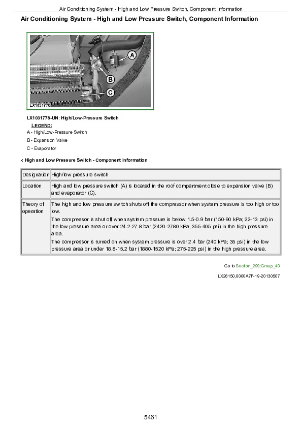
  Air-Conditioning System….133
  Tips On Using the Air-Conditioning System….134
  Storage Rack….135
  Additional Storage Area….136
  Dome Light….137
  Adjust the Steering Wheel….138
  Beacon Light….139
  Install Monitor….140
  Sockets….141
  Multiple Power-Outlet Socket Strip (If Equipped)….143
  Service Socket (CAN Bus)….144
  Cigarette Lighter and Ashtray….145
  ISOBUS Socket….146
  Open Windows….147
  Opening Sun Roof (Option)….148
  Routing Cables Through the Window….149
Section 30: Break-In Period….150
  After the First 4 and 8 Hours of Operation….151
  Within the First 100 Hours of Operation….153
  After the First 100 Hours of Operation….154
Section 35: Prestarting Checks….156
  Prestarting Checks….156
  Comply with Operator's Manuals of Implement Manufacturers….160
Section 40: Operating the Engine….642
  Important Information Regarding the Engine….642
  Start the Engine….642
  Cold-Weather Starting Aids….165
  Coolant Heater….166
  Starting the Engine With a Slave Battery….167
  Engines with Turbocharger….168
  Engine Protection….169
  Towing the Tractor….465
  Parking the Tractor….171
  Stopping the Engine….642
  Battery Cut-Off Switch (if equipped)….173
Section 42: Exhaust Cleaning System….174
  Exhaust Filter Cleaning, General Information….175
  Exhaust Cleaning System, Information for Operator….176
  Access the Engine Menu on the Digital Display….178
  Passive Exhaust Filter Cleaning….179
  Automatic Exhaust Filter Cleaning….180
  Exhaust Filter Cleaning with Tractor Parked….182
  Exhaust Filter, Service Cleaning….187
Section 45: Operating the Tractor — General….188
  Reduce Fuel Consumption….190
  Select Correct Travel Speed….193
  Notes on Changing to a Different Size of Tire….194
  Travel Speed Tables….195
  Travel Speeds, PowrQuad™ PLUS Transmission for 30 km/h (16/16) – Tires with SRI 750 and 800….196
  Travel Speeds, PowrQuad™ PLUS Transmission for 30 km/h (16/16) – Tires with SRI 825….198
  Travel Speeds, PowrQuad™ PLUS Transmission for 40 km/h (16/16) – Tires with SRI 700 and 800….200
  Travel Speeds, PowrQuad™ PLUS Transmission for 40 km/h (16/16) – Tires with SRI 825….202
  Travel Speeds, PowrQuad™ PLUS Transmission for 40 km/h (24/24) – Tires with SRI 700 and 725….204
  Travel Speeds, PowrQuad™ PLUS Transmission for 40 km/h (24/24) – Tires with SRI 750 and 775….206
  Travel Speeds, PowrQuad™ PLUS Transmission for 40 km/h (24/24) – Tires with SRI 800 and 825….208
  Travel Speeds, AutoQuad™ PLUS Transmission for 40 km/h (24/24) – Tires with SRI 700 and 725….210
  Travel Speeds, AutoQuad™ PLUS Transmission for 40 km/h (24/24) – Tires with SRI 750 and 775….212
  Travel Speeds, AutoQuad™ PLUS Transmission for 40 km/h (24/24) – Tires with SRI 800 and 825….214
  Travel Speeds, AutoQuad™ PLUS Transmission with EcoShift for 40 km/h (24/24) – Tires with SRI 700 and 725….216
  Travel Speeds, AutoQuad™ PLUS Transmission with EcoShift for 40 km/h (24/24) – Tires with SRI 750 and 775….218
  Travel Speeds, AutoQuad™ PLUS Transmission with EcoShift for 40 km/h (24/24) – Tires with SRI 800 and 825….220
  Engage Front-Wheel Drive….222
  Tractors with TLS Front Axle….224
  Engage Creeper Transmission….225
  Engage Differential Lock….226
  Hydraulic Foot Brakes….227
  Emergency and Park Brake System….229
  Hydraulic Trailer Brakes….230
  Trailer Air Brakes….231
  Park the Tractor….233
  Chock Block….234
Section 47: Operating the Tractor — PowrQuad™ PLUS….235
  Shifting the PowrQuad™ PLUS Transmission….236
  PowrQuad™ PLUS Transmission — Settings….239
Section 48: Operating the Tractor — AutoQuad™ PLUS….242
  Shifting the AutoQuad™ PLUS Transmission….243
  AutoQuad Plus Transmission — Settings….248
Section 50: Hitch….251
  Hitch Control….252
  Hitch – Maximum Lifting Force….254
  Hitch Remote Control….255
  Hitch – Lift Limit….256
  Hitch – Transporting Mounted Implements….257
  Hitch – Hitch Dampening….258
  Hitch – Adjust Rate of Implement Drop….259
  Hitch – Adjust the Rate of Lift….260
  Hitch – Adjust Working Depth….261
  Hitch – Load/Depth Adjustment….262
  Hitch – Using Draft Control….264
  Hitch – Float Position….266
  Hitch – Direct Control….267
  Front Hitch….268
  Three-Point Hitch….274
  Flat Steel Draft Links….275
  Telescopic Draft Links….276
  Quick-Coupling (Hook-Type) Draft Links….277
  Attach Three-Point Hitch Mounted and Drawn Implements….280
  Leveling the Implement….282
  Center Link….283
  Center Link Positions….284
  Quick-Coupling (Hook-Type) Center Link….285
  Lift Links….287
  Adjust for Vertical Float….289
  Sway Blocks (If Equipped)….290
  Stabilizer Bar….291
  Stabilizing System (If Equipped)….292
  Draft Link, Categories 2 and 3N — Adjust Spreading Dimension….293
Section 51: iTEC™ Basic — Intelligent Total Equipment Control….295
  iTEC™ Basic – Operating the Intelligent Total Equipment Control….296
Section 55: Power Take-Off….298
  PTO Guard….299
  Operating Instructions….301
  PTO Options….303
  PTO Speeds….304
  Front PTO….305
  Operating PTOs….306
  Select Standard Speed of Rear PTO….308
  Operating the Rear PTO by Fender Control….310
  Connect an Implement to the Rear PTO….312
Section 60: Ballast….314
  Selection of Weights….315
  Ballasting Rear Wheels….316
  Measuring Rear Wheel Slip….317
  Wheel Weights….318
  Filling Tires With Liquid Ballast….319
  Draining the Tires….320
  Attach the Pick-Up Weight to the Front Hitch….321
  Pre-Assembling the Pick-Up Weight….322
  Attaching to Rear Hitch….325
  Attaching to Basic Weight….327
  Weight in the Three-Point Hitch….330
  Install Front Weights….331
Section 65: Wheels, Tires….332
  General Wheel, Tire, and Tread Guidelines….334
  Changing to a Different Tire Size….336
  Change Wheels Safely….337
  Tires on Front Wheels….339
  Checking and Adjusting Toe-In….340
  Check Toe-In….341
  Adjust Toe-In (Tractors with Front-Wheel Drive Axle)….343
  Adjust Toe-In – Adjustable Front Axle without Front-Wheel Drive….344
  Adjustable Front Axle without Front-Wheel Drive – Tighten Axle Bolts and Wheels Bolts….345
  Adjustable Front Axle without Front-Wheel Drive – Adjust Tread Widths….346
  Adjustable Front Axle without Front-Wheel Drive – Tread Widths without Axle Extensions….349
  Instructions for Front-Wheel Tread Adjustment with Rims for 2, 8 and 16 Positions….350
  Front-Wheel Tread Adjustment with Rims for 2 Positions….352
  Front-Wheel Tread Adjustment with Rims for 8 Positions….356
  Front-Wheel Tread Adjustment with Rims for 16 Positions….359
  Adjust the Fixed Fenders….365
  Adjust the Pivoting Fenders….368
  Fender Settings….371
  Front Axle – Adjust Steering Stop….378
  Instructions for Rear Wheel Tread Adjustment with Rims for 2, 8 and 16 Positions – Flanged Axle….383
  Rear Wheel Tread Adjustment with Rims for 2 Positions – Flanged Axle….385
  Rear Wheel Tread Adjustment with Rims for 8 Positions – Flanged Axle….388
  Rear Wheel Tread Adjustment with Rims for 16 Positions – Flanged Axle….389
  Service Tires Safely….395
  Tire Combinations – Tractors without Front-Wheel Drive Axle….396
  Tire Combinations – Tractors with Front-Wheel Drive Axle….397
  Calculate Tire Combinations (Graphic)….401
  Calculate Tire Combination….402
  Tire Pressures….406
  Tire Inflation Pressure Guidelines….407
  Front Wheels – Recommended Pressures, Bias Single Front Tires (Two-Wheel Drive)….408
  Front Wheels – Recommended Pressures, Group 42….409
  Front Wheels – Recommended Pressures, Group 42 (Continued)….411
  Front Wheels – Recommended Pressures, Group 43….413
  Front Wheels – Recommended Pressures, Group 43 (Continued)….415
  Rear Wheels – Recommended Pressures, Group 47….417
  Rear Wheels – Recommended Pressures, Group 47 (Continued)….421
  Rear Wheels – Recommended Pressures, Group 47 (Continued)….421
Section 70: Additional Equipment — Hydraulic System….641
  Selective Control Valves….424
  Selective Control Valves – Pressure Adjustment on 450 Series….425
  Levers for Mechanical Selective Control Valves….426
  Additional Functions for Mechanical Selective Control Valves….428
  Selective Control Valves – Couplers….429
  Selective Control Valves – Hose Unions….430
  Selective Control Valves – Maximum Permissible Oil Withdrawal….431
  Selective Control Valves – Oil Withdrawal with Hydrostatic Drive (with PC Hydraulic System)….433
  Selective Control Valves – Oil Withdrawal with Hydrostatic Drive (with PFC Hydraulic System)….434
  Additional Oil Reservoir….435
  Pressure-Free Return Circuit….436
  Mechanical Multi-Function Lever with Front-Loader Dampening….437
Section 71: Additional Equipment — Other….439
  Drawbar….440
  Proper Use of Drawbar….441
  Locking the Height-Adjustable Trailer Hitch….453
  Locking the Hitch Pins….443
  Front Loader Implements – Front Loader Brackets for Loaders H310 and H340….446
  Front Jaw Hitch….448
  Tow Hitch (Piton-Fix/Ball-Type)….450
  Height-Adjustable Trailer Hitch….453
  Remote Control (If Equipped)….455
  Hydraulic Pick-Up Hitch (Mechanically Actuated)….456
  Lockable Tank Filler Cap….459
Section 75: Transport….460
  Driving on Public Roads….461
  Towing Loads and Transporting with Ballast….463
  Transporting the Tractor….464
  Towing the Tractor….465
  Freeing a Mired Machine….466
Section 80: Fuel, Lubricants, Hydraulic Oil and Coolant….467
  John Deere Break-In™ Plus Engine Oil….468
  Engine Oil and Filter Service Intervals—Interim Tier 4 and Stage III B Engines….469
  Transmission and Hydraulic Oil….470
  Front-Wheel Drive Axle Oil….472
  Grease….474
  Mixing of Lubricants….475
  Lubricant Storage….476
  Alternative and Synthetic Lubricants….477
  John Deere COOL-GARD™ II Coolant Extender….478
  Heavy Duty Diesel Engine Coolant….479
  Supplemental Coolant Additives….480
  Operating in Warm Temperature Climates….481
  Testing Diesel Engine Coolant….482
  Storing Fuel….483
  Handling and Storing Diesel Fuel….485
  Diesel Fuel….485
  Minimizing the Effect of Cold Weather on Diesel Engines….487
  Lubricity of Diesel Fuel….489
  Biodiesel Fuel….490
  Testing Diesel Fuel….492
  Oilscan™ and CoolScan™….493
Section 85: Lubrication and Periodic Service….517
  Scope of This Manual….495
  Service Tractor Safely….496
  Observe Service Intervals….501
  Safe Maintenance and Cleaning….498
  Using High Pressure Washers….499
  Lubricate All Lubricating Points….622
  Service Intervals….501
  General Instructions Regarding the Condition of the Tractor….502
  Open the Hood….503
  Open Service Doors….504
  Access to Battery….505
  Access to Fuses….506
  Jack Up the Tractor – Lifting Points….508
  Important Instructions Regarding Alternator….511
  Service After the First 100 Hours….512
  Service As Required….513
  Check/Replace Hydraulic Hoses….514
  Other Service Jobs….515
  Note Regarding the Service Interval for Engine Coolant….612
  Periodic Service….517
  Service (Daily / Every 10, 250 and 500 Hours)….518
  Service (Every 750, 1000, 1500 Hours, Annually and Every 2000 Hours)….521
  Service (Every 2 Years, Every 3000, 4500, 6000 and 10000 Hours)….522
Section 90: Service / Daily or Every 10 Hours….523
  Check Brakes….524
  Check the Lights….525
  Clean Dust-Unloading Valve….526
  Clean the Radiator, Condenser and Area Surrounding the Engine….642
  Check Coolant Level….529
  Air Brake System – Check for Condensed Water….530
  Check Transmission/Hydraulic Oil Level….531
  Check Engine Oil Level….532
  Check the Fuel Filters….533
  Lubricate Front Hitch….534
  Lubricate the Front Axle and U.j. Shafts….535
  Lubricate Hitch Jaw….537
  Lubricate the Three-Point Hitch….538
  Lubricating the Pick-Up Hitch….555
Section 95: Service / Every 250 Hours….540
  Checking Neutral Start Circuit….541
  Service the Fuel Tank….542
  Front-Wheel Drive Axle – Check Oil Level in Axle Housing….543
  Front-Wheel Drive Axle – Check Oil Level in Final Drives….544
  Front PTO – Check Oil Level….545
  Check Air Intake Hoses….546
  Front Axle without Front-Wheel Drive – Tighten Screws….547
  Tighten Wheel Bolts and Wheel Weights….548
  Front Loader Bracket – Tighten Screws on H310 and H340 Loaders….550
  Front Hitch – Tighten the Screws….551
  Drawbar – Tighten the Screws….552
  Height-Adjustable Trailer Hitch – Tighten the Screws….553
  Ball-Type Tow Hitch with Forced Steering System – Tighten the Screws….554
  Pick-Up Hitch….555
  Front Axle without Front-Wheel Drive – Lubricate the Grease Fittings….556
  Lubricate Pivoting Fenders….557
  Rear PTO, Lubricate Stub Shaft Support….558
  Check the Manually-Operated Trailer Hitch for Wear….559
  Check the Manually-Operated Hitch for Wear (Italy and Spain Only)….561
  Check the Remote-Controlled Trailer Hitch for Wear….563
  Trailer Hitch, Check the Guide Rails….566
  Check for Wear at Tow Hitch (Piton Fix)….567
  Check for Wear at Ball-Type Tow Hitch….568
  Check the Drawbar for Wear….569
  Check Tow Hook on Pick-Up Hitch for Wear….571
  Change Activated Carbon Filters….573
Section 100: Service / Every 500 Hours….574
  Change Engine Oil….575
  Engine – Change the Oil Filter….577
  Change the Fuel Filters….578
  Lubricate the Rear Axle….579
  Engine – Check Drive Belt for Wear….580
  Check Engine Ground Connection….581
  Check the Cab Ground Connection….582
Section 105: Service / Every 750 Hours….583
  Replace Transmission/Hydraulic Oil Filters….584
  Front PTO – Change Oil Filter (if equipped)….585
Section 110: Service / Once Every Year….586
  Check the Seat Belt….587
  Test Engine Coolant Using Test Strips – 4-Cylinder Engines….588
  Inspect Hydraulic Hoses….590
  Other Annual Service Jobs….591
Section 115: Service / Every 1500 Hours or 2 Years….592
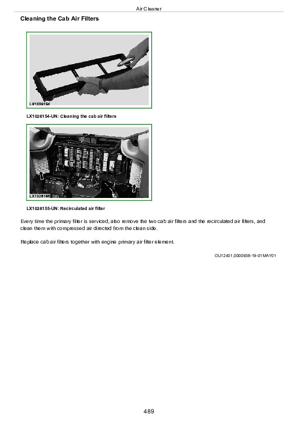
  Change Cab Air Filters and Recirculation Air Filters….593
  Change the Engine Air Cleaner….597
  Engine – Change Filter of Oil Separator in Crankcase Vent….599
  Changing Oil in Front-Wheel Drive Axle and Final Drives….600
  Change Oil In Front-Wheel Drive Axle Housing….601
  Change Oil in Front-Wheel Drive Final Drives….602
  Change Transmission/Hydraulic Oil and Oil Filter….603
  Front PTO – Change Oil and Oil Filter (if equipped)….606
  Air brake system – Change air-drier cartridge….607
Section 117: Service / Every 4500 Hours….608
  Engine Air Cleaner – Change the Secondary Element….609
Section 120: Service / Every 6000 Hours….611
  Note Regarding the Service Interval for Engine Coolant….612
  Change the Coolant – 4-Cylinder Engines….613
Section 125: Service / As Required….616
  Clean Cab Air Filters….617
  Bleed Air from Fuel System….621
  Lubricate All Lubricating Points….622
  Operator's Seat….623
  Starter Motor….624
  Replace Diesel Particulate Filter (DPF)….625
  Replace the Drive Belt….626
  Starter Relays….629
  Fuse and Relay of Electrical Starting Aid….630
  Fuse and Relays of Battery Cut-Off Switch (BBO)….631
  Fuses (PLB)….632
  Fuses and Relays (PSB)….634
  Fuses and Relays (LCS) and (FRM), General Information – Tractors with Cab….636
  Fuses and Relays (LCS) and (FRM)….638
Section 130: Troubleshooting….640
  Hydraulic System….641
  Engine….642
  Electrical System….699
Section 135: Diagnostic Trouble Codes and Customization….645
  Operation and Entering the Diagnostic Addresses with Digital Display (Customer Level)….646
  AIC – Control Software….649
  BLC – Control Software….650
  CCU – Control Software….652
  ECU – Control Software….653
  EIC – Control Software….657
  FCC – Control Software….658
  HCC – Control Software….659
  OIC – Control Software….660
  PTF – Control Software….661
  PTQ – Control Software….662
  TEI – Control Software….663
  RPT – Control Software….664
  SFA – Control Software….665
  TEC – Control Software….666
  TIQ – Control Software….667
Section 140: Storage….668
  Storage for a Long Period….669
  Removing Tractor from Storage….670
Section 145: Specifications….671
  Dimensions – 6090MC to 6110MC Tractors, Without Front-Wheel Drive Axle….673
  Dimensions – 6090MC to 6110MC Tractors, With Front-Wheel Drive Axle….675
  Dimensions – 6090RC to 6110RC Tractors, With Front-Wheel Drive Axle….677
  Engine – 6090MC to 6110MC Tractors….679
  Engine – 6090RC to 6110RC Tractors….680
  PTO Power Output – 6090MC to 6110MC Tractors….682
  PTO Power Output – 6090RC to 6110RC Tractors….683
  Transmission – 6090MC to 6110MC Tractors….684
  Transmission – 6090RC to 6110RC Tractors….685
  Hitch – 6090MC to 6110MC Tractors….686
  Hitch – 6090RC to 6110RC Tractors….687
  Hydraulic System – 6090MC to 6110MC….688
  Hydraulic System – 6090RC to 6110RC….689
  Oil Withdrawal – 6090MC to 6110MC Tractors….690
  Oil Withdrawal – 6090RC to 6110RC Tractors….691
  Loads and Weights….692
  How to Calculate Maximum Permissible Download on Trailer Hitch….694
  Towed Mass….696
  How to Calculate Permissible Mass….697
  Vibration….698
  Electrical System….699
  Capacities – 6090MC to 6110MC Tractors….700
  Capacities – 6090RC to 6110RC Tractors….701
  Sound Level….702
  Permissible Front Axle Load in Relation to Tires (Normal Operation) – 6090MC to 6110MC Tractors, Without Front-Wheel Drive….703
  Permissible Front Axle Load in Relation to Tires (Front Loader Operation) – 6090MC to 6110MC Tractors, Without Front-Wheel Drive….704
  Permissible Front Axle Load in Relation to Tires (Normal Operation) – 6090MC, 6100MC, 6090RC and 6100RC Tractors, With Front-Wheel Drive….705
  Permissible Front Axle Load in Relation to Tires (Front Loader Operation) – 6090MC, 6100MC, 6090RC and 6100RC Tractors, With Front-Wheel Drive….709
  Permissible Front Axle Load in Relation to Tires (Normal Operation) – 6110MC and 6110RC Tractors, With Front-Wheel Drive….713
  Permissible Front Axle Load in Relation to Tires (Front Loader Operation) – 6110MC and 6110RC Tractors, With Front-Wheel Drive….717
  Permissible Rear Axle Load in Relation to Tires – 6090MC, 6100MC, 6090RC and 6100RC Tractors….721
  Permissible Rear Axle Load in Relation to Tires – 6110MC and 6110RC Tractors….725
  Unified Inch Bolt and Screw Torque Values….728
  Metric Bolt and Screw Torque Values….730
  Safety Note Regarding the Subsequent Installation of Electrical and Electronic Appliances and/or Components….732
Section 150: Serial Numbers….733
  Type Plates….734
  Plate for Product Identification and Serial Numbers of Components….735
  Plate for Product Identification Number….737
  Engine Serial Number….738
  Transmission Serial Number….739
  Front-Wheel Drive Serial Number….740
  Serial Number of Operator's Cab….741
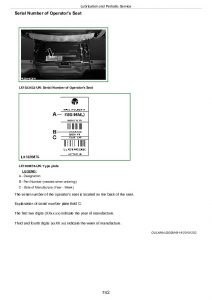
  Serial Number of Operator's Seat….742
  Sub-Assembly Serial Numbers….743
Section 155: Glossary….745
  Glossary….745

John Deere Tractors 6090MC, 6100MC, 6110MC, 6090RC, 6100RC and 6110RC Operator’s Manual (OMAL216252)


INSTANT DOWNLOAD


Posted on

John Deere Tractors Models 6090MC, 6090RC, 6100MC, 6100RC, 6110MC, 6110RC Repair Service Manual (TM406619)


INSTANT DOWNLOAD


Complete Repair Technical Manual for John Deere Tractors 6090MC, 6090RC, 6100MC, 6100RC, 6110MC, 6110RC, with  workshop information to maintain, repair, and rebuild like professional mechanics.

John Deere 2WD or MFWD Tractors 6090MC, 6100MC, 6110MC, 6090RC, 6100RC & 6110RC (Worldwide Edition) workshop technical manual (repair) includes:
* Numbered table of contents easy to use so that you can find the information you need fast.
* Detailed sub-steps expand on repair procedure information
* Numbered instructions guide you through every repair procedure step by step.
* Notes, cautions and warnings throughout each chapter pinpoint critical information.
* Bold figure number help you quickly match illustrations with instructions.
* Detailed illustrations, drawings and photos guide you through every procedure.
* Enlarged inset helps you identify and examine parts in detail.

tm406619 English- Tractors 6090MC – 6110MC,6090RC – 6110RC Repair – (Worldwide Edition) Technical Manual.pdf
tm406611 Bulgarian – Трактори 6090MC – 6110MC, 6090RC – 6110RC Ремонт -: (Световна версия)
tm406616 Czech – Traktory 6090MC – 6110MC, 6090RC – 6110RC Opravy -: (Celosvětové vydání)
tm406618 Dutch – Tractoren 6090MC – 6110MC, 6090RC – 6110RC repareren -: (Wereldwijde uitgave)
tm406622 Finnish – Traktorit 6090MC – 6110MC, 6090RC – 6110RC, korjaus -: (Maailmanlaajuinen painos)
tm406625 Latvian-lettish – Traktoru 6090MC – 6110MC, 6090RC – 6110RC remonts -: (Starptautisks izdevums)
tm406626 Lithuanian – Traktorių 6090MC – 6110MC, 6090RC – 6110RC remontas -: (Tarptautinis leidinys)
tm406628 French – Tracteurs 6090MC – 6110MC, 6090RC – 6110RC Remise en état -: (Édition mondiale)
tm406629 German – Traktoren 6090MC – 6110MC, 6090RC – 6110RC Reparatur -: (Weltweite Ausgabe)
tm406635 Hungarian – 6090MC – 6110MC, 6090RC – 6110RC Traktorok Javítás -: (Egész világon érvényes kiadás)
tm406639 Italian – Riparazione dei trattori 6090MC – 6110MC, 6090RC – 6110RC -: (Edizione universale)
tm406654 Portuguese – Tratores 6090MC – 6110MC, 6090RC – 6110RC – Reparação -: (Edição Mundial)
tm406658 Romanian – Repararea tractoarelor 6090MC – 6110MC, 6090RC – 6110RC -: (Ediţie mondială)
tm406667 Swedish – Reparation av traktorer 6090MC – 6110MC, 6090RC – 6110RC -: (Världsupplaga)
tm406674 Danish – Traktor 6090MC – 6110MC, 6090RC – 6110RC reparation -: (Global udgave)
tm406676 Slovak – Traktory 6090MC – 6110MC, 6090RC – 6110RC oprava -: (Celosvetové vydanie)
tm406678 Norwegian – Traktorer 6090MC – 6110MC, 6090RC – 6110RC, reparasjon -: (Global versjon)
tm406680 Turkish – Traktörler 6090MC – 6110MC, 6090RC – 6110RC Onarım -: (Dünya Çapındaki Sürüm)
tm406682 Slovenian – Traktorji 6090MC – 6110MC, 6090RC – 6110RC Popravila -: (Izvedba za vse celine in države)
tm4066a5 Croatian – Traktori 6090MC – 6110MC, 6090RC – 6110RC Popravak -: (Svjetsko izdanje)
tm111119 English – JDPS Master Tool Manual -: (Worldwide Edition) Technical Manual
tm112219 English – GreenStar™ 3 2630 Display Technical Manual
tm117919 English – StarFire™ 3000 Technical Manual
tm123119 English – 4640 Universal Display Technical Manual
tm135419 English – StarFire™ 6000, 6000HA, and StarFire™ 6000 Integrated Receiver Technical Manual

Total Pages: 1,675 pages
File Format: PDF (PC/Mac/Android/Kindle/iPhone/iPad; bookmarked, ToC, Searchable, Printable)
Language: English etc.

MAIN SECTIONS
Foreword
   Safety
      Safety
   General
      General Information – Specifications
      General Information – Tests and Adjustments
      General Information – Predelivery Inspection
   Engine
      Engine – Removal and Installation of Components
   Fuel, Air-Intake, Cooling, and Exhaust System
      Fuel System
      Air Intake System
      Cooling System
      Exhaust System
   Electrical System
      Electrical System – Connectors
      Electrical System – Charging Circuit
      Electrical System – Starter Circuit
      Electrical System – Headlights
   Electronic Control Units
      Removal and Installation of Control Units
      Terminating Resistors, Removal and Installation
   Drive Train (without Transmission)
      Drive Train (without Transmission) – Removal and Installation of Components
      Drive Train (without Transmission) – U.J. Shafts and Torsion Dampers
      Drive Train (without Transmission) – Mechanical Front-Wheel Drive
      Drive Train (without Transmission) – Differential
      Drive Train (without Transmission) – Hydraulic Pump Drive
      Drive Train (without Transmission) – Final Drives
      Drive Train (without Transmission) – Rear PTO Options
      Drive Train (without Transmission) – Front PTO
      Drive Train (without Transmission) – Front Implement Drive
   PowrQuad™ Transmission
      PowrQuad™ Transmission – Removal and Installation of Components
      PowrQuad™ Transmission – Transmission Shift Control
      PowrQuad™ Transmission – PowrQuad™ Module
      PowrQuad™ Transmission – Creeper Transmission
      PowrQuad™ Transmission – Option Transmission
      PowrQuad™ Transmission – Range Transmission
   Steering
      Steering – Hydrostatic Steering
   Brakes
      Brakes – Brake Valve
      Brakes – Rear Brakes
      Brakes – Hydraulic Trailer Brake
      Brakes – Air-Brake System
      Brakes – Park Brake
   Hydraulic System
      Hydraulic System – General Information
      Hydraulic System – Controls
      Hydraulic System – Oil Filter, Additional Oil Reservoir, Charge Pump, and Hydraulic Pump
      Hydraulic System – Priority 1 to 3 Control Blocks
      Hydraulic System – Rear Hitch
      Hydraulic System – Selective Control Valves (SCVs) and Couplers
      Hydraulic System – Independent Control Valves (ICVs)
   Machine-Specific Systems
      Machine-Specific Systems – Removal and Installation of Components
      Machine-Specific Systems – Main Frame
      Machine-Specific Systems – Fenders, Front Wheels, and Rear Wheels
      Machine-Specific Systems – Trailer Hitch and Swinging Drawbar
      Machine-Specific Systems – Hydraul. Pick-Up Hitch
   Suspension Systems
      Suspension Systems – Suspended Front-Wheel Drive Axle
   Operator’s Cab
      Removal and Installation of Components
      Operator’s Cab – Operation and Control Devices
      Operator’s Cab – Air-Conditioning System
      Operator’s Cab – Seats
      Operator’s Cab – Operator’s Cab
   Special Tools
      General Information

tm406619 – Tractors 6090MC – 6110MC,6090RC – 6110RC Repair -: (Worldwide Edition)

Table of Contents

Foreword

Section 05: Safety

Group 05: Safety Measures

General Information – Safety – Summary of References

Recognize Safety Information

Understand Signal Words

Follow Safety Instructions

Prevent Machine Runaway

Operating the Tractor Safely

Operating the Loader Tractor Safely

Passenger Seat

Use Safety Lights and Devices

Towing Trailers/Implements Safely (Mass)

Use Caution On Slopes and Uneven Terrain

Freeing a Mired Machine

Avoid Backover Accidents

Handle Fluids Safely—Avoid Fires

Handling Batteries Safely

Prepare for Emergencies

Avoid High-Pressure Fluids

Service Cooling System Safely

Remove Paint Before Welding or Heating

Avoid Heating Near Pressurized Fluid Lines

Work In Ventilated Area

Avoid Contact with Agricultural Chemicals

Handle Agricultural Chemicals Safely

Stay Clear of Rotating Drivelines

Wear Protective Clothing

Protect Against Noise

Practice Safe Maintenance

Avoid Hot Exhaust

Exhaust Filter Cleaning

Clean Exhaust Filter Safely

Read Operator Manuals for ISOBUS Implements

Use Steps and Handholds Correctly

Use Seat Belt Properly

Park Machine Safely

Use Proper Lifting Equipment

Construct Dealer-Made Tools Safely

Support Machine Properly

Work in Clean Area

Illuminate Work Area Safely

Service Machines Safely

Service Accumulator Systems Safely

Service Tires Safely

Use Proper Tools

Service Front-Wheel Drive Tractor Safely

Avoid Eye Contact With Radar

Keep ROPS Installed Properly

Replace Safety Signs

Replace Safety Signs

Dispose of Waste Properly

Live With Safety

Safety Measures on Electronic Control Units

Servicing Electronic Control Units

Welding Near Electronic Control Units

Keep Electronic Control Unit Connectors Clean

Safety Instructions for Replacing a Halogen Bulb

Safety Instructions for Replacing Xenon (HID) Bulbs and Ballast Units

Section 10: General Information

Group 05: General Information – Specifications

Specifications – Summary of References

Engine Specifications

PTO Power Output

Capacities

Air Intake System

Electrical System

Hydraulic System

Clutch Operation

PowrQuad PLUS™ Transmission

Differential

Differential Lock

Final Drives

Front-Wheel Drive

FWD Axle with TLS

Cab Suspension

Hydraulic Brakes

Auxiliary Brake

Park Lock

Hitch

Immobilizer

Front Hitch

Ground Travel Speeds

Front and Rear Wheels

Dimensions and Weights

Handling and Storing Diesel Fuel

Diesel Fuel

Minimizing the Effect of Cold Weather on Diesel Engines

Biodiesel Fuel

Lubricity of Diesel Fuel

Diesel Engine Break-In Oil

John Deere Break-In™ Plus Engine Oil

Transmission and Hydraulic Oil

Oil for Front-Wheel Drive Axle

Heavy Duty Diesel Engine Coolant

Supplemental Coolant Additives

Grease

Oil Filters

Mixing of Lubricants

Lubricant Storage

Operating in Warm Temperature Climates

Alternative and Synthetic Lubricants

Unified Inch Bolt and Screw Torque Values

Metric Bolt and Screw Torque Values

Hydraulic system inch fitting torques

Hydraulic system metric fitting torques

Product Identification and Component Serial Number Plate

Plate for Product Identification Number

Engine Serial Number

Transmission Serial Number

Front-Wheel Drive Serial Number

Operator’s Cab Serial Number

Operator’s seat serial number

Subassembly Serial Numbers

Group 10: General Information – Tests and Adjustments

Tests and Adjustments – Summary of References

Using High-Pressure Washers

Preliminary Engine Test

Visual Inspection of the Fuel System

Check the Fuel Filter

Check the Function of the Fuel Transfer Pump

Bleeding the Fuel System

Primary Air Cleaner Element, Removal and Installation

Check the Secondary (Safety) Element

Drain Coolant

Check Transmission/Hydraulic System Oil Level

Group 15: General Information – Predelivery Inspection

Predelivery Inspection

Section 20: Engine

Group 00: Engine – Removal and Installation of Components

Engine – Removal and Installation of Components, Summary of References

Engine – Removal and Installation of Components, Special Tools

Engine – Removal and Installation of Components, Repair Specifications

Remove the Engine, Preliminary Work

Remove the Engine

Install Engine

Install the Engine, Additional Work

Engine Mounting

Replace the Engine Mountings, Preliminary Work

Replace the Front Engine Mountings

Replace the Rear Engine Mounting

Replace the Engine Mountings, Further Work

Section 30: Fuel, Air-Intake, Cooling and Exhaust Systems

Group 10: Fuel System

Fuel System – Summary of References

Electric Conductivity of the Fuel Hoses

Fuel Tank, Removal and Installation

Fuel Level Sensor, Removal and Installation

Bleeding the Fuel System

Group 15: Air Intake System

Air Intake System – Summary of References

Visual Inspection of the Air Intake System

Primary Air Cleaner Element, Removal and Installation

Check the Secondary (Safety) Element

Group 20: Cooling System

Cooling System – Summary of References

Open the Hood

Hood, Removal and Installation

Cooler Package, Removal and Installation

Radiator, Removal and Installation

Replace the Drive Belt

Routing of Drive Belt

Automatic Belt Tensioner, Removal and Installation

Group 30: Exhaust System

Exhaust System – Summary of References

Exhaust Filter — Handling and Disposal of Ash from the Diesel Particulate Filter

Exhaust Cleaning System, Important Information

Exhaust System to Top Right, Removal and Installation

Section 40: Electrical System

Group 05: Electrical System – Connectors

Electrical System – Connectors, Summary of References

CRIMP SNAP IN Connectors

General

Using high-pressure washers

Strip Wire Ends

Install Electrical Terminal

WEATHER PACK Connectors

METRI PACK Connector with Terminal Lock at the Rear

METRI PACK Connector with Terminal Lock at the Front

METRI PACK Connectors

Connectors for Electronic Control Units

Connector

CRIMP SNAP IN Connectors

KOSTAL Connectors

DEUTSCH Connectors

Individual Terminals

Bosch™ Connectors

Repair DEUTSCH™ Implement Connectors

Repair Molex™ Connectors

Repair SUMITOMO™ Connectors

Repair YAZAKI™ Connectors

Group 10: Electrical System – Charging Circuit

Electrical System – Charging Circuit, Summary of References

Electrical System – Disconnect the Electrical Circuit

Electrical System – Remove and Install Battery

Electrical System – Alternator Removal and Installation

Group 15: Electrical System – Starter Motor Circuit

Electrical System – Starter Circuit, Summary of References

Electrical System – Starter Removal and Installation

Group 20: Electrical System – Headlights

Electrical System – Lights, Summary of References

General information

Electrical System – Adjust Headlights

Adjusting the Lights on the Cab Frame

Safety Instructions for Replacing a Halogen Bulb

Safety Instructions for Replacing Xenon (HID) Bulbs and Ballast Units

Section 45: Electronic Control Units

Group 05: Removal and Installation of Control Units

Electronic Control Units – Summary of References

Instructions when Replacing a Control Unit

Central Control Unit – Removal and Installation

Instrument Unit – Removal and Installation

Front Chassis Control Unit – Removal and Installation

Immobilizer Control Unit – Removal and Installation

Group 10: Terminating Resistors – Removal and Installation

Terminating Resistors – Summary of References

Terminating Resistor A002 in Instrument Unit

CAN Bus Terminating Resistor A010 (CAN Bus – Vehicle)

CAN BUS Terminating Resistor A053 (CAN BUS – Implement)

A131 – CAN BUS Terminating Resistor (Engine CAN Bus)

Section 50A: Drive Train (without Transmission)

Group 00: Drive Train (without Transmission) – Removal and Installation of Components

Drive train (without transmission) – Removal and installation of components, Summary of references

Drivetrain (without Transmission) – Special Tools

Drivetrain (without Transmission) – Repair Specifications

Drain Transmission/Hydraulic Oil

Fill with Transmission/Hydraulic Oil

Remove the Final Drives

Install the Final Drives

Rear PTO Removal

Install the Rear PTO

Remove Front PTO

Installing of the front PTO

Group 10: Drivetrain (without Transmission) – Universal-Jointed Shafts and Torsion Dampers

Drive Train (without Transmission) – U.J. Shafts and Torsion Dampers, Summary of References

U-Jointed Shafts and Torsion Dampers – Repair Specifications

U.J. Shafts and Torsion Dampers – Removing the U.J. Shaft (MFWD)

Universal-joint shafts and torsion dampers – Reconditioning the u.j. shaft (MFWD)

U.J. Shafts and Torsion Dampers – Installing the U.J. Shaft (MFWD)

U.J. Shafts and Torsion Dampers – Remove the Engine U.J. Shaft

Universal-Joint Shafts and Torsion Dampers – Installing the Engine Universal-Joint shafts

Universal-Joint Shafts and Torsion Dampers – Removing the Torsion Dampers

Universal-Joint Shafts and Torsion Dampers – Replacing the Torsion Damper Bearing

Universal-Jointed Shafts and Torsion Dampers – Installing the Torsion Damper

Group 15: Drivetrain (without Transmission) – Mechanical Front-Wheel Drive

Drive Train (without Transmission) – Mechanical Front-Wheel Drive, Summary of References

Mechanical Front-Wheel Drive – Special Tools

Mechanical Front-Wheel Drive – Repair Specifications

Mechanical Front-Wheel Drive – Reconditioning the MFWD Solenoid Valve

Mechanical front-wheel drive – Sectional view

Mechanical Front Wheel Drive – Exploded View

Removing the Mechanical Front-Wheel Drive

Mechanical front-wheel drive – Removing the FWD clutch

Mechanical Front-Wheel Drive – Repair the Front-Wheel Drive Clutch

Mechanical Front-Wheel Drive – Installing the FWD Clutch

Mechanical front-wheel drive – Adjusting axial play of output driveshaft

Installing the Mechanical Front-Wheel Drive

Group 20: Drivetrain (without Transmission) – Differential

Drive Train (without Transmission) – Differential, Summary of References

Differential – Special Tools

Differential – Repair Specifications

Differential – Handling KJD10672 – Lifting tool for differential

Differential – Replacing wheel speed sensor

Differential – Replacing Solenoid Valve for Differential Lock

Differential – Sectional view

Differential – Exploded view

Removing the differential

Recondition the Differential

Install Differential

Differential – Adjusting the Tapered Roller Bearing and Backlash

Group 25: Drive Train (without Transmission) – Hydraulic Pump Drive

Drive Train (without Transmission) – Hydraulic Pump Drive, Summary of References

Hydraulic Pump Drive – Special Tools

Hydraulic Pump Drive – Repair Specifications

Hydraulic Pump Drive – Sectional View

Hydraulic Pump Drive – Exploded View

Remove Hydraulic Pump Drive

Installing the Hydraulic Pump Drive

Adjusting the Hydraulic Pump Drive

Hydraulic Pump Drive – Check and Adjust the Backlash of the Pump Drive Pinion

Group 30: Drivetrain (without Transmission) – Final Drives

Drive Train (without Transmission) – Final Drives, Summary of References

Final Drives – Special Tools

Final Drives – Repair Specifications

Final Drives – Sectional View

Exploded View of Final Drives

Disassemble the Final Drives

Reconditioning the Final Drives

Assemble the Final Drives

Final Drives – Checking and Adjusting Rolling Drag Torque

Group 35: Drivetrain (without Transmission) – Rear PTO Options

Drive Train (without Transmission) – Rear PTO Options, Summary of References

Rear PTO Options – Special Tools

Rear PTO Options – Repair Specifications

Rear PTO Options – Replacing the Output Shaft Seal Ring (540 rpm)

Rear PTO Options – Replacing the Output Shaft Seal Ring

Rear PTOs – Replacing the O-ring for reversible PTO shaft

Rear PTOs – Sectional view

Rear PTOs – exploded view

Rear PTO Options – Removing the PTO Clutch

Rear PTO Options – Reconditioning the PTO Clutch

Rear PTOs – Reconditioning the PTO brake

Rear PTO Options – Installing the PTO Clutch

Rear PTO Options – Removing the PTO Drive Train

Rear PTO Options – Reconditioning the Output Shaft

Rear PTO Options – Reconditioning the Countershaft

Rear PTOs – Reconditioning the PTO shifter

Rear PTO Options – Install the PTO Drive Train

Rear PTOs – Removing the PTO gear transmission (reversible)

Rear PTOs – Reconditioning the output driveshaft (reversible)

Rear PTOs – Reconditioning the countershaft (reversible)

Rear PTOs – Installing the PTO gear transmission (reversible)

Rear PTOs – Adjusting the tapered roller bearing of the output driveshaft (540 rpm)

Rear PTO Options – Adjusting the Tapered Roller Bearing of the Countershaft

Rear PTO Options – Adjusting the Tapered Roller Bearing of the Bearing Support

Rear PTO Options – Reconditioning the PTO Shaft Spline Identifier

Rear PTO Options – Removing the Modulating Valve

Rear PTO Options – Reconditioning the Modulating Valve

Rear PTO Options – Installing the Modulating Valve

Rear PTOs – Reconditioning Y04 solenoid valve for rear PTO

Rear PTOs – Replacing B06 sensor for rear PTO speed

Rear PTOs – Reconditioning the oil sight glass

Group 40: Drivetrain (without Transmission) – Front PTO

Drive train (without transmission) – Front PTO, Summary of references

Front PTO – Repair Specifications

Front PTO – Sectional View

Front PTO – Exploded view

Front PTO – Changing the Oil Filter

Disassembling the Front PTO

Assemble Front PTO

Front PTO – Replacing the front PTO speed sensor

Front PTO – Replacing the front PTO proportional solenoid valve

Front PTO – Replacing the Oil Cooler

Group 45: Drivetrain (without Transmission) – Front Implement Drive

Drive Systems – Front Implement Drive, Summary of References

Front Implement Drive – General Information

Front Implement Drive – Repair Specifications

Front Implement Drive – Exploded View

Removing the Front Implement Drive

Reconditioning the Front Implement Drive

Installing the Front Implement Drive

Section 50C: PowrQuad™ Transmission

Group 00: PowrQuad™ Transmission – Removal and Installation of Components

PowrQuad™ Transmission – Removal and Installation of Components, Summary of References

PowrQuad™ Transmission – Installation and Removal of Components, Special Tools

PowrQuad™ Transmission – Removal and Installation of Components, Repair Specifications

PowrQuad™ Plus transmission, Removal and installation

AutoQuad™ Plus transmission, Removal and installation

Remove the PowrQuad™ Transmission – Preliminary Work

Remove the PowrQuad™ Transmission

Install the PowrQuad™ Transmission

Remove the Creeper or Option Transmissions

Install the Creeper or Option Transmissions

Remove the Range Transmission

Install the Range Transmission

Group 10: PowrQuad™ Transmission – Transmission Shift Unit

PowrQuad™ Transmission – Transmission Shift Controls, Summary of References

PowrQuad™ Transmission – Check and Adjust the Shift Unit and Park Lock

PowrQuad™ Transmission – Recondition the Selector Grip for PowrQuad™ PLUS and AutoQuad™ PLUS

PowrQuad™ Transmission – Remove the Shift Unit

PowrQuad™ Transmission – Repair the Shift Unit

PowrQuad™ Transmission – Install the Shift Unit

PowrQuad™ Transmission – Remove the Clutch Actuation Mechanism

PowrQuad™ Transmission – Repair the Clutch Actuation Mechanism

PowrQuad™ Transmission – Install the Clutch Actuation Mechanism

Group 15: PowrQuad™ Transmission – PowrQuad™ Module

PowrQuad™ Transmission – PowrQuad™ Module, Summary of References

PowrQuad™ Transmission – Special Tools, Summary of References

PowrQuad™ Transmission – Repair Specifications

PowrQuad™ Transmission – Transmission Components

PowrQuad™ Transmission – Replacing the Temperature Sensor and Pressure Switches

PowrQuad™ Transmission – Remove and Install the Oil Filter Housing

PowrQuad™ Transmission – Replacing the Oil Filter Housing

PowrQuad™ Transmission – Replacing Seal Ring for Transmission Input Shaft

PowrQuad™ Transmission – Remove and Install the Front Valve Housing

PowrQuad™ Transmission – Remove and Install the Valves in the Front Valve Housing

PowrQuad™ Transmission – Removing and Installing the Front Transmission Cover

PowrQuad™ Transmission – Removing and Installing the Valves in the Front Transmission Cover

PowrQuad™ Transmission – Remove and Install the Shift Valve Housing

PowrQuad™ Transmission – Remove and Install Valves in Shift Valve Housing

PowrQuad™ Transmission – Remove the Transmission Oil Pump

PowrQuad™ Transmission – Repair the Transmission Oil Pump

PowrQuad™ Transmission – Installing the Transmission Oil Pump

PowrQuad™ Transmission – Removing the Gear-Shift Planetary Drive.

PowrQuad™ Transmission – Repair the Gear-Shift Planetary Drive

PowrQuad™ Transmission – Install the Gear-Shift Planetary Drive

PowrQuad™ Transmission – Removing the B1 Brake Housing

PowrQuad™ Transmission – Reconditioning the B1 Brake

PowrQuad™ Transmission – Installing the B1 Brake Housing

PowrQuad™ Transmission – Removing the B2-B3 Brake Housing

PowrQuad™ Transmission – Reconditioning the B2 Brake

PowrQuad™ Transmission – Reconditioning the B3 Brake

PowrQuad™ Transmission – Installing the B2-B3 Brake Housing

PowrQuad™ Transmission – Removing the C4 Clutch

PowrQuad™ Transmission – Recondition the C4 Clutch

PowrQuad™ Transmission – Installing the C4 Clutch

PowrQuad™ Transmission – Removing the Reverse Brake

PowrQuad™ Transmission – Repair the Reverse Brake

PowrQuad™ Transmission – Installing the Reverse Brake

PowrQuad™ Transmission – Removing the Forward Clutch with Planetary Drive (Travel Direction)

PowrQuad™ Transmission – Recondition the Forward Clutch with Planetary Drive (Travel Direction)

PowrQuad™ Transmission – Installing Forward Clutch with Planetary Drive (Travel Direction)

PowrQuad™ Transmission – Replacing the Clutch Carriers for C4 Clutch and Forward Clutch

PowrQuad™ Transmission – Replace the Transmission Output Shaft and Rear PTO Drive Shaft

Group 20: PowrQuad™ Transmission – Creeper Transmission

PowrQuad™ Transmission – Reconditioning the Creeper Transmission, Summary of References

PowrQuad™ Transmission – Creeper Transmission – Repair Specifications

PowrQuad™ Transmission – Reconditioning the Creeper Transmission

PowrQuad™ Transmission – Creeper Transmission – Reconditioning the Shift Cover

Group 25: PowrQuad™ Transmission – Option Transmission

PowrQuad™ Transmission – Reconditioning the Option Transmission, Summary of References

PowrQuad™ Transmission – Option Transmission – Repair Specifications

PowrQuad™ Transmission – Reconditioning the Option Transmission

Group 30: PowrQuad™ Transmission – Range Transmission

PowrQuad™ Transmission – Range Transmission – Reconditioning, Summary of References

PowrQuad™ Transmission – Repair Specifications

PowrQuad™ Transmission – Range Transmission – Sectional View

PowrQuad™ Transmission – Reconditioning the Range Transmission

PowrQuad™ Transmission – Assembling the Range Transmission

PowrQuad™ Transmission – Reconditioning the Shift Cover

PowrQuad™ Transmission – B104 – Replacing the Transmission Output Speed Sensor

Section 60A: Steering system

Group 10: Steering – Hydrostatic Steering

Steering – Hydrostatic Steering, Summary of References

Hydrostatic Steering – Special Tools, Summary of References

Hydrostatic Steering – Repair Specifications

Hydrostatic Steering – Disconnect/Connect the Steering or Brake Hoses

Hydrostatic Steering – Removing the Steering Wheel

Hydrostatic Steering – Installing the Steering Wheel

Hydrostatic Steering – Removing Trim Panels of Steering Column

Hydrostatic Steering – Installing Trim Panels of Steering Column

Hydrostatic Steering – Removing and Installing Steering Column

Hydrostatic Steering – Exploded View of Steering Column

Hydrostatic Steering – Removing the Steering Unit

Hydrostatic Steering – Exploded View of Steering Unit

Hydrostatic Steering – Installing the Steering Unit

Section 60B: Brakes

Group 10: Brakes – Brake Valve

Brakes – Brake Valve, Summary of References

Brake Valve – Special Tools, Summary of References

Brake Valve – Repair Specifications

Brake Valve – Disconnecting/Connecting Steering or Brake Hoses

Brake Valve, Exploded View

Remove Foot Brake Valve

Install Foot Brake Valve

Group 15: Brakes – Rear Brakes

Brakes – Rear Brakes, Summary of References

Rear Brakes – Special Tools, Summary of References

Rear Brakes – Specifications

Rear Brakes – Exploded View

Remove the Rear Brakes

Install the Rear Brakes

Rear Brakes – Check Brake Pistons for Return Movement and Leakage

Group 20: Brakes – Hydraulic Trailer Brake

Brakes – Hydraulic Trailer Brake, Summary of References

Hydraulic Trailer Brake – Repair Specifications

Hydraulic Trailer Brake – Repair Instructions

Hydraulic Trailer Brake – Change the Trailer Brake Valve

Hydraulic Trailer Brake – Replacing the Coupler

Group 25: Brakes – Air Brake System

Brakes – Air-brake system, Summary of references

Air Brake System – Special Tools, Summary of References

Air Brake System – Repair Specifications

Air Brake System – Safety Instructions

Air Brake System – Installing the Compressed-Air Hoses

Air Brake System – Replace the Compressor

Air Brake System – Reconditioning the Compressor

Air-Brake System – Replacing the Compressed-Air Tank

Air-Brake System – Replacing the Trailer Control Valve (for Dual-Line Brakes)

Air-brake system – Replacing the trailer control valve (for single-line brakes)

Air Brake System – Change the Coupling Ends

Group 30: Brakes – Park Brake

Brakes – Park Brake, Summary of References

Park Brake – Special Tools, Summary of References

Park brake – Repair specifications

Park Brake, Exploded View

Park Brake – Removing the Control Lever

Removing the Park Brake

Installing the park brake

Park Brake – Installing the Control Lever

Park Brake – Replace the Brake Cable

Section 70: Hydraulic System

Group 05: Hydraulic System – General Information

Hydraulic System – General Information, Summary of References

Hydraulic System – General Safety and Repair Information

Group 10: Hydraulic System – Controls

Hydraulic System – Recondition the Controls, Summary of References

Repair Specifications

Selective Control Valves (M-SCVs) – Removing and Installing the Actuating Elements

Selective Control Valves (M-SCV) – Adjusting the Control Cable

Removing and Installing the Multi-Function Lever (on Shift Console) for M-ICVs

Adjusting the Multi-Function Lever (on Shift Console) for M-ICVs

Group 15: Hydraulic System – Oil Filter, Additional Oil Reservoir, Charge Pump, and Hydraulic Pump

Hydraulic System – Oil Filter, Additional Oil Reservoir, Charge Pump and Hydraulic Pump, Summary of References

Repair Specifications

F1 – Removal and Installation of the Hydraulic Oil Filter

F5 – Recondition Hydraulic Oil Filter

Removing the P3 and P4 – Hydraulic Pump (PC Hydraulic System)

Removing the G52 – Mounting Plate with Lube Oil Valve (PC Hydraulic System)

Removing and Installing the V20 – Lube Oil Valve (PC Hydraulic System)

Installing the G52 – Mounting Plate with Lube Oil Valve (PC Hydraulic System)

Installing the P3 and P4 – Hydraulic Pump (PC Hydraulic System)

Removing and Installing the P1 and P5 – Charge Oil Pump (PFC Hydraulic System)

Removing and Installing the V10 – Lube Oil Valve (PFC Hydraulic System)

Removing and Installing the R6 – Additional Oil Reservoir (PFC Hydraulic System)

R2 – Oil Reservoir, Hydraulic Pump (PFC Hydraulic System)

G1 – PFC Hydraulic System – Hydraulic Pump, Remove and Install the Pressure-and-Flow Regulator

Removing and Installing the P2 and P6 – Hydraulic Pump (PC Hydraulic System)

Group 20: Hydraulic System – Priority 1 to 3 Control Blocks

Hydraulic System – Repair the Priority 1 to 3 Control Blocks, Summary of References

Reconditioning the Priority 1 to 3 Control Blocks – Special Tools, Summary of References

Repair Specifications

Remove and Install G37 – Priority Valve (PC Hydraulic System)

Recondition G37 – Priority Valve (PC Hydraulic System)

Remove and Install the G2 – Priority 1 Control Block (PFC Hydraulic System)

Reconditioning G2 – Priority 1 Control Block (PFC Hydraulic System)

Removing and Installing the G11, G44, and G45 – Control block with or without Priority 2 (PFC Hydraulic System)

Reconditioning G11 – Priority 2 Control Block (PFC Hydraulic System)

Repair G44 – Control Block (without Priority 2) (PFC Hydraulic System)

Repair G45 – Control Block (without Priority 2) (PFC Hydraulic System)

Removing and Installing the G53 – Priority 3 Control Block (PFC Hydraulic System)

Reconditioning G53 – Priority 3 Control Block (PFC Hydraulic System)

Group 25: Hydraulic System – Rear Hitch

Hydraulic System – Repair the Rear Hitch, Summary of References

Reconditioning the Rear Hitch – Special Tools, Summary of References

Other Material

Repair Specifications

Removing and Installing the M008 – Stepper Motor (Hitch Valve)

Removing and Installing the G38 and G16 – Hitch Valve

Reconditioning the G38 – Hitch Valve (Rear Hitch) (PC Hydraulic System)

Reconditioning the G16 – Hitch Valve (Rear Hitch) (PFC Hydraulic System)

Removing and Installing the B021 – Position Sensor and Toothed Segment (Rear Hitch)

Removing and Installing the Rockshaft (Rear Hitch)

Removing and Installing the C11 and C12 – Lift Cylinders (Rear Hitch)

Reconditioning the C11 and C12 – Lift Cylinders (Rear Hitch)

B019 and B020 – Remove and Install Draft Sensors and Draft Link Bearing Pins (Rear Hitch)

Rear Hitch – Recondition the Hydraulic Center Link (HCL)

Group 30: Hydraulic System – Selective Control Valves (SCVs) and Couplers

Repair the Selective Control Valves (SCVs) and Couplers – Summary of References

Repair Specifications

Removing and Installing the Selective Control Valves (SCVs)

Reconditioning the G17 – Selective Control Valves (M-SCV 100)

Reconditioning the G18 – Selective Control Valves (M-SCV 200)

Reconditioning the G27 – Selective Control Valves (M-SCV 450)

J5 and J6 – Recondition the Couplers (SCV)

Group 35: Hydraulic System – Independent Control Valves (ICVs)

Repair the Independent Control Valves (ICV) – Summary of References

Repair Specifications

Removing and Installing the G24, G25, and G26 – Independent Control Valves (M-ICV)

Reconditioning the G24, G25, and G26 – Independent Control Valves (M-ICV)

Section 80A: Machine-Specific Systems

Group 00: Machine-Specific Systems – Removal and Installation of Components

Machine-specific systems – Removal and installation of components, Summary of references

Machine-Specific Systems – Special Tools

Machine-Specific Systems – Repair Specifications

Remove the Axle, Preliminary Work

Remove Suspended Front-Wheel Drive Axle

Install Suspended Front-Wheel Drive Axle

Remove the Front-Wheel Drive Axle

Installing the Front-Wheel Drive Axle

Remove Front Axle

Install the Front Axle

Removing the front hitch

Installing the front hitch

Remove the Front Axle Support, Preliminary Work

Remove the Front Axle Support for Suspended Front-Wheel Drive Axle

Remove the Front Axle Support for Front-Wheel Drive Axle

Remove Front Axle Support at Front Axle

Installing the Front Axle Support

Install Front Axle Support, Additional Work

Group 10: Machine-Specific Systems – Main Frame

Machine-Specific Systems – Main Frame, Summary of References

Main Frame – Repair Specifications

Main Frame and Attachments

Group 15: Machine-Specific Systems – Fenders, Front Wheels, and Rear Wheels

Machine-specific systems – Front wheels, rear wheels, and fender, Summary of references

Front Wheels, Rear Wheels and Fenders – Special Tools

Front wheels, rear wheels, and fenders – Repair specifications

Front wheels, rear wheels, and fenders – Pivoting front fender

Front wheels, rear wheels, and fenders – Removing a front wheel

Front wheels, rear wheels, and fenders – Reconditioning a front rim

Front wheels, rear wheels, and fenders – Installing a front wheel

Front wheels, rear wheels, and fenders – Removing the rear wheels (with flanged axle)

Front wheels, rear wheels, and fenders – Reconditioning the rear rim (with flanged axle)

Front wheels, rear wheels, and fenders – Installing the rear wheels (with flanged axle)

Front wheels, rear wheels, and fenders – Removing the rear wheels (with rack-and-pinion axle)

Front wheels, rear wheels, and fenders – Reconditioning the rear rim (with rack-and-pinion axle)

Front wheels, rear wheels, and fenders – Installing the rear wheels (with rack-and-pinion axle)

Front wheels, rear wheels, and fenders – Installing the reinforced rear wheel

Group 20: Machine-Specific Systems – Trailer Hitch and Drawbar

Machine-Specific Systems – Trailer Hitch and Swinging Drawbar, Summary of References

Repair Specifications

Check the Manually-Operated Hitch for Wear

Check the Manually-Operated Hitch for Wear (Italy and Spain Only)

Check the Remote-Controlled Trailer Hitch for Wear

Trailer Hitch, Checking the Guide Rails

Checking the Tow-Hook for Wear

Checking the Hitch Ball for Wear

Check Drawbar for Wear

Removing and Installing the Center Link Bracket

Removing and Installing the Guide Rails

Reconditioning the Automatic Trailer Hitch

Remote Control for Automatic Trailer Hitch

Reconditioning the Height-Adjustable Trailer Hitch (Italy and Spain Only)

Drawbar

Swinging Drawbar with Pick-Up Hitch

Tightening Torques on High-Clearance Drawbar

Adjusting the High-Clearance Drawbar

Adjusting the Holding Tab

Attaching Safety Decals on the Swinging Drawbar

Group 25: Machine-Specific Systems – Hydraul. Wagon Hitch

Machine-Specific Systems – Hydraulic Pick-Up Hitch, Summary of References

Pick-Up Hitch – Specifications

Hydraulic Pick-Up Hitch — General Safety and Repair Information

Check Tow Hook on Pick-Up Hitch for Wear

Removing and Installing the Pick-Up Hitch

Pick-Up Hitch – Exploded View

Pick-Up Hitch – Control Lever and Lift Links

Pick-Up Hitch – Hydraulic Parts

Pick-Up Hitch – Recondition the Retainer Spring

Pick-Up Hitch – Recondition the Latch Housing

Pick-Up Hitch – Recondition the Hydraulic Cylinder

Section 80B: Suspension Systems

Group 10: Suspension Systems – Suspended Front-Wheel Drive Axle

Suspension Systems – Suspended Front-Wheel Drive Axle, Summary of References

Suspension Systems – Special Tools, Summary of References

Repair Specifications

Relieving Hydraulic System Pressure

Removing/Installing the Oscillation Limiter

Remove the Panhard Link

Install the Panhard Link

Removing and Installing Linkage

Removing Position Sensor of Suspended Front-Wheel Drive Axle

Reconditioning Position Sensor of Suspended Front-Wheel Drive Axle

Installing Position Sensor of Suspended Front-Wheel Drive Axle

Remove Hydraulic Cylinder

Recondition the Hydraulic Cylinder

Install Hydraulic Cylinders

Remove the Control Block

Recondition the Valves in the Control Block

Install the Control Block

Remove and Install Accumulator

Reconditioning the Accumulator

Remove and Recondition the Bearing Support

Install the Bearing Support

Section 90: Operator’s Cab

Group 00: Removal and Installation of Components

Operator’s Cab – Installation and Removal of Components, Summary of References

Operator’s Cab – Installation and Removal of Components, Special Tools

Operator’s Cab – Installation and Removal of Components, Repair Specifications

Tilt the Operator’s Cab Upward and Downward – Special Tools

Tilt the Operator’s Cab Upward

Tilt Operator’s Cab Downward

Remove Operator’s Cab

Install Operator’s Cab

Removing the Operator’s Platform

Installing the Operator’s Platform

Testing and Adjusting Shift Units

Group 10: Operator’s Cab – Operation and Control Devices

Operator’s Cab – Controls and Instruments, Summary of References

Controls and Instruments – Replacing an Ignition Key with Chip (Immobilizer)

Group 15: Operator’s Cab – Air-Conditioning System

Operator’s Cab – Air-Conditioning System, Summary of References

Air-Conditioning System – Special Tools, Summary of References

Air-Conditioning System – Repair Specifications

Air Conditioning System – Observing AC Hose Torques

Air Conditioning System – Safety at Work

Air Conditioning System – Storage of Refrigerant Containers

Air Conditioning System – Important

Air-Conditioning System – Service Work

Air Conditioning System – Preventive Maintenance

Air-Conditioning System – Test with Air Conditioning Service Unit

Air-Conditioning System – Air-Conditioning Service Unit, Filling with Refrigerant Oil

Air conditioning system – Instructions for starting up the DENSO air conditioning compressor

Air-Conditioning System – Leak Test

Air-Conditioning System – Removing the Compressor

Air conditioning system – Checking level in the compressor

Air-Conditioning System – Disassembling the Magnetic Clutch

Air Conditioning System – Checking the Clutch Hub Clearance

Air-Conditioning System – Install Compressor

Air-Conditioning System – Remove and Install Condenser

Air-Conditioning System – Remove and Install Receiver-Drier

Air-Conditioning System – Remove and Install Evaporator with Expansion Valve

Air-Conditioning System – Replace Expansion Valve

Air-Conditioning System – Arrangement of Condensation Drain Hoses

Air-Conditioning System – Remove and Install Blower Motor

Air-Conditioning System – Remove and Install Blower Motor Resistors

Air-Conditioning System – Remove and Install Recirculation Air Filter

Air-Conditioning System – Remove and Install Heater Valve

Air-Conditioning System – Adjust Heater Valve Bowden Cable

Air-Conditioning System – Remove and Install Thermostat Switch

Air-Conditioning System – Adjust Thermostat Switch Bowden Cable

Air-Conditioning System – Remove and Install High/Low-Pressure Switch

Air-Conditioning System – Remove and Install Control Console for Ventilation System

Group 30: Operator’s Cab – Seats

Operator’s Cab – Seat, Summary of References

Seat Tools — Summary of References

Repair Specifications

Other Material

General Information on Seat Repairs

Air Comfort Seat MSG95GL, Removal and Installation

Air Comfort Seat MSG95GL, Boot Removal and Installation

Air Comfort Seat MSG95GL – Removal and Installation of Compressor

Air Comfort Seat MSG95GL – Air Spring Removal and Installation

Air Comfort Seat MSG95GL – Seat Suspension Removal and Installation

Air Comfort Seat MSG95GL, Vehicle Connection Harness, Removal and Installation

Air Comfort Seat MSG95GL – Seat Suspension Harness, Removal and Installation

Air Comfort Seat MSG95GL – Actuation for Height Adjustment Removal and Installation

Air Comfort Seat MSG95GL, Check and Adjust the Bowden Cables for Height Adjustment

Air Comfort Seat MSG95GL, Removal and Installation of Bowden Cable for Height Adjustment Downward

Air Comfort Seat MSG95GL, Removal and Installation of Bowden Cable for Height Adjustment Upward

Air Comfort Seat MSG95GL, Level Control Removal and Installation

Air Comfort Seat MSG95GL – Adjust Level Control (Micro-Switch, Vent Valve)

Air Comfort Seat MSG95GL – Air Hoses Removal and Installation

Air Comfort Seat MSG95GL – Air Distributor Removal and Installation

Instructional Seat, Seat Belt Removal and Installation

Group 35: Operator’s Cab – Operator’s Cab

Operator’s Cab, Summary of References

Special Tools – Summary of References

Remove and Install the Cab Frame

Cab Mounting Torques

Windshield, Removal and Installation

Rear Window, Removal and Installation

Adjust Windshield and Rear Window Contact Pressure

Sun Roof, Removal and Installation

Adjust the Door Lock

Cab Door, Removal and Installation

Shift Console Trim Panel, Removal and Installation

Inner Roof Trim, Removal and Installation

Section 300: Special Tools

Group 05: General Information

Special Tools – General Information

John Deere Tractors Models 6090MC, 6090RC, 6100MC, 6100RC, 6110MC, 6110RC Repair Service Manual (TM406619)


INSTANT DOWNLOAD


Posted on

John Deere Tractors Models 6090MC, 6090RC, 6100MC, 6100RC, 6110MC, 6110RC Diagnostics Technical Manual (TM406519)

INSTANT DOWNLOAD


Complete Diagnosis & Tests Technical Manual with electrical wiring diagrams for John Deere 6090MC, 6090RC, 6100MC, 6100RC, 6110MC, 6110RC Tractors, with all the shop information to maintain, diagnose, and rebuild like professional mechanics.

John Deere European Tractors 6090MC, 6100MC, 6110MC, 6090RC, 6100RC, 6110RC (Worldwide Edition) workshop Diagnosis & Tests technical manual includes:
* Numbered table of contents easy to use so that you can find the information you need fast.
* Detailed sub-steps expand on repair procedure information
* Numbered instructions guide you through every repair procedure step by step.
* Troubleshooting and electrical service procedures are combined with detailed wiring diagrams for ease of use.
* Notes, cautions and warnings throughout each chapter pinpoint critical information.
* Bold figure number help you quickly match illustrations with instructions.
* Detailed illustrations, drawings and photos guide you through every procedure.
* Enlarged inset helps you identify and examine parts in detail.

TM406519 English – 6090MC, 6100MC, 6110MC, 6090RC, 6100RC, 6110RC Tractors Diagnosis – (Worldwide Edition) Technical Manual.pdf
tm406511 Bulgarian – Диагностика на трактори 6090MC, 6100MC, 6110MC, 6090RC, 6100RC, 6110RC -: (Световна версия)
tm406516 Czech – Diagnostika traktorů 6090MC, 6100MC, 6110MC, 6090RC, 6100RC, 6110RC -: (Celosvětové vydání)
tm406518 Dutch – Tractoren 6090MC, 6100MC, 6110MC, 6090RC, 6100RC, 6110RC diagnose -: (Wereldwijde uitgave)
tm406522 Finnish – Traktorien 6090MC, 6100MC, 6110MC, 6090RC, 6100RC ja 6110RC diagnostiikka -: (Maailmanlaajuinen painos)
tm406525 Latvian-lettish – Traktoru 6090MC, 6100MC, 6110MC, 6090RC, 6100RC, 6110RC diagnostika -: (Starptautisks izdevums)
tm406526 Lithuanian – Traktorių 6090MC, 6100MC, 6110MC, 6090RC, 6100RC, 6110RC diagnostika -: (Tarptautinis leidinys)
tm406528 French – Diagnostics, tracteurs 6090MC, 6100MC, 6110MC, 6090RC, 6100RC, 6110RC -: (Édition mondiale)
tm406529 German – Traktoren 6090MC, 6100MC, 6110MC, 6090RC, 6100RC, 6110RC Diagnose -: (Weltweite Ausgabe)
tm406535 Hungarian – Traktorok 6090MC, 6100MC, 6110MC, 6090RC, 6100RC, 6110RC diagnosztika -: (Egész világon érvényes kiadás)
tm406539 Italian – Diagnosi trattori 6090MC, 6100MC, 6110MC, 6090RC, 6100RC, 6110RC -: (Edizione universale)
tm406554 Portuguese – Diagnósticos dos Tratores 6090MC, 6100MC, 6110MC, 6090RC, 6100RC e 6110RC -: (Edição Mundial)
tm406558 Romanian – Diagnosticarea tractoarelor 6090MC, 6100MC, 6110MC, 6090RC, 6100RC, 6110RC -: (Ediţie mondială)
tm406567 Swedish – Traktor 6090MC, 6100MC, 6110MC, 6090RC, 6100RC, 6110RC, felsökning -: (Världsupplaga)
tm406574 Danish – Traktor 6090MC, 6100MC, 6110MC, 6090RC, 6100RC, 6110RC Fejlsøgning -: (Global udgave)
tm406576 Slovak – Traktory 6090MC, 6100MC, 6110MC, 6090RC, 6100RC, 6110RC Diagnostika -: (Celosvetové vydanie)
tm406578 Norwegian – Traktorer 6090MC, 6100MC, 6110MC, 6090RC, 6100RC, 6110RC diagnose -: (Global versjon)
tm406580 Turkish – 6090MC, 6100MC, 6110MC, 6090RC, 6100RC, 6110RC Traktörler için Diyagnostik -: (Dünya Çapındaki Sürüm)
tm406582 Slovenian – Traktorji 6090MC, 6100MC, 6110MC, 6090RC, 6100RC, 6110RC Diagnostika -: (Izvedba za vse celine in države)
tm4065a5 Croatian – Dijagnostika traktora 6090MC, 6100MC, 6110MC, 6090RC, 6100RC, 6110RC -: (Svjetsko izdanje)

Total Pages: 5,554pages
File Format: PDF (PC/Mac/Android/Kindle/iPhone/iPad; bookmarked, ToC, Searchable, Printable)
Language: English etc.

MAIN SECTIONS
 Foreword
   General
      Safety
      General References
   Diagnostic Trouble Codes
      AIC Control Software
      BLC Control Software
      CCU Control Software
      CRU Control Software
      ECU Control Software
      EIC Control Software
      FCC Control Software
      HCC Control Software
      OIC Control Software
      PDU Control Software
      PTF Control Software
      PTQ Control Software
      RPT Control Software
      SFA Control Software
      SMB Control Software
      TEC Control Software
      TEI Control Software
      TIQ Control Software
      VTV Control Software
   Observable Symptoms and System Diagnostics
      Engine
      Fuel, Air Intake, and Cooling Systems
      Electrical System
      Electronic Control Units
      Drive Train (without Transmission)
      PowrQuad™ Transmission
      Steering
      Brakes
      Hydraulic System
      Machine-Specific Systems
      Suspension Systems
      Operator’s Cab
   Engine
      Exhaust Aftertreatment System, Theory of Operation
      Tests and Adjustments
   Fuel, Air Intake, and Cooling Systems
      General Information
      Fuel System, Theory of Operation
      Air Intake System, Theory of Operation
      Cooling System, Theory of Operation
      Cold-Weather Starting System, Theory of Operation
      Fuel, Air Intake, and Cooling Systems – Tests and Adjustments
   Fuel, Air Intake, and Cooling Systems – Component Information
      Fuel System, Component Information
      Cooling System, Component Information
      Charge Air Circuit, Component Information
      Cold-Weather Starting System, Component Information
   Electrical System
      Summary of References
      Operational schematics
      50AA – Starter Motor and Charging Circuit
      50AC – External Cold Start Aid
      50BA – Lights
      50BB – Flood Lights
      50BC – Dome Light
      50BD – Turn-Signal Lights
      50CA – Operator’s Seat
      50CB – Acoustic Alarms
      50CC – Windshield and Rear Window Wipers
      50CD – Heater/Ventilation/Air-Conditioning System
      50CE – Sockets
      50CF – Radio
      50CH – Accessories (General Information)
      50EA – TEC Control Software and Implement CAN Bus
      50FA – Electronic Engine Control
      50FB – Immobilizer
      50FC – Fuel System
      50GA – PowrQuad™ Transmission
      50GH – Differential Lock
      50GI – Front-Wheel Drive
      50GJ – Rear PTO
      50GK – Front PTO
      50GL – Brakes
      50HA – Rear Hitch
      50HD – Suspended Front-Wheel Drive Axle
      50IA – Display
      50JA – CAN Bus Systems
      50X – Ground Connections
   Electronic Control Units
      Electronic Control Units – General Information
      Electronic Control Units – Interactive Tests and Calibrations
      Electronic Control Units – Information on Programming
      Electronic Control Units – Theory of Operation
      Electronic Control Units – Diagnostic Schematics
      Electronic Control Units – Component Information
      Electronic Control Units – Tests and Adjustments
      Immobilizer Control Unit
      AIC Control Software
      BLC Control Software
      CCU Control Software
      ECU Control Software
      EIC Control Software
      FCC Control Software
      HCC Control Software
      OIC Control Software
      PDU Control Software
      PTF Control Software
      PTQ Control Software
      RPT Control Software
      SFA Control Software
      SMB Control Software
      TEC Control Software
      TEI Control Software
      TIQ Control Software
      VTV Control Software
   Electrical Connectors, Wiring Harnesses and Components
      Summary of Electrical Components and Harnesses
      Electrical Components – Assemblies
      Electrical Components – Sensors
      Electrical Components – Various Devices and Equipment
      Electrical Components – Protective Equipment
      Electrical Components – Power Supply and Alternator
      Electrical Components – Control and Signal Devices
      Electrical Components – Relays
      Electrical Components – Electrical Motors
      Electrical Components – Resistors
      Electrical Components – Switches
      Electrical Components – Diodes
      Electrical Components – Wiring Harnesses
      Connector
      Ground Points
      Electrical Components – Solenoid Valves and Solenoids
      Electrical Components – Other
   Drive Train (without Transmission)
      Drive Train (without Transmission) – Operational Checks
      Drive Train (without Transmission) – Theory of Operation
      Drive Train (without Transmission) – Tests and Adjustments
   PowrQuad™ Transmission
      PowrQuad™ Transmission – General Information
      PowrQuad™ Transmission – Operational Checks
      PowrQuad™ Transmission – Theory of Operation
      PowrQuad™ Transmission – Schematics
      PowrQuad™ Transmission – Tests and Adjustments
   Drive Train – Component Information
      Drive Train (without Transmission) – Component Information
      PowrQuad™ Transmission – Component Information
   Steering
      Steering – General Information
      Steering – Operational Checks
      Steering – Theory of Operation
      Steering – Schematics
      Steering – Tests and Adjustments
   Brakes
      Brakes – General Information
      Brakes – Operational Checks
      Brakes – Theory of Operation
      Brakes – Schematics
      Brakes – Tests and Adjustments
   Steering and Brakes – Component Information
      Steering – Component Information
      Brakes – Component Information
   Hydraulic System
      Hydraulic System – General Information
      Hydraulic System – Operational Checks
      Hydraulic System – Theory of Operation
      Oil Filter, Additional Oil Reservoir, Charge Pump and Hydraulic Pump – Theory of Operation
      Rear Hitch – Theory of Operation
      Front Hitch – Theory of Operation
      Selective Control Valves (SCVs) – Theory of Operation
      Independent Control Valves (ICVs) – Theory of Operation
      Hydraulic System – Schematics
      Hydraulic System – Tests and Adjustments
   Hydraulic System – Component Information
      Hydraulic System – Component Information
   Machine-Specific Systems
      Machine-Specific Systems – Operational Checks
      Machine-Specific Systems – Tests and Adjustments
   Suspension Systems
      Suspension Systems – Operational Checks
      Suspended Front-Wheel Drive Axle – Theory of Operation
      Suspended Front-Wheel Drive Axle – Schematics
      Suspended Front-Wheel Drive Axle – Tests and Adjustments
   Suspension Systems – Component Information
      Suspended Front-Wheel Drive Axle – Component Information
   Operator’s Cab
      Operator’s Cab – Operational Checks
      Operator’s Cab – Theory of Operation
      Operator’s Cab – Tests and Adjustments
   Operator’s Cab – Component Information
      Air Conditioning System – Component Information
   Special Tools
      General Information

tm406519 – 6090MC, 6100MC, 6110MC, 6090RC, 6100RC, 6110RC Tractors Diagnosis -: (Worldwide Edition)

Table of Contents

Foreword

Section 210: General Information

Group 05: Safety Measures

General Information – Safety – Summary of References

Recognize Safety Information

Understand Signal Words

Follow Safety Instructions

Prevent Machine Runaway

Operating the Tractor Safely

Operating the Loader Tractor Safely

Passenger Seat

Use Safety Lights and Devices

Towing Trailers/Implements Safely (Mass)

Use Caution On Slopes and Uneven Terrain

Freeing a Mired Machine

Avoid Backover Accidents

Handle Fluids Safely—Avoid Fires

Handling Batteries Safely

Prepare for Emergencies

Avoid High-Pressure Fluids

Service Cooling System Safely

Remove Paint Before Welding or Heating

Avoid Heating Near Pressurized Fluid Lines

Work In Ventilated Area

Avoid Contact with Agricultural Chemicals

Handle Agricultural Chemicals Safely

Stay Clear of Rotating Drivelines

Wear Protective Clothing

Protect Against Noise

Practice Safe Maintenance

Avoid Hot Exhaust

Exhaust Filter Cleaning

Clean Exhaust Filter Safely

Read Operator Manuals for ISOBUS Implements

Use Steps and Handholds Correctly

Use Seat Belt Properly

Park Machine Safely

Use Proper Lifting Equipment

Construct Dealer-Made Tools Safely

Support Machine Properly

Work in Clean Area

Illuminate Work Area Safely

Service Machines Safely

Service Accumulator Systems Safely

Service Tires Safely

Use Proper Tools

Service Front-Wheel Drive Tractor Safely

Avoid Eye Contact With Radar

Keep ROPS Installed Properly

Replace Safety Signs

Replace Safety Signs

Dispose of Waste Properly

Live With Safety

Safety Measures on Electronic Control Units

Servicing Electronic Control Units

Welding Near Electronic Control Units

Keep Electronic Control Unit Connectors Clean

Safety Instructions for Replacing a Halogen Bulb

Safety Instructions for Replacing Xenon (HID) Bulbs and Ballast Units

Group 10: General References

General Information – General References, Summary of References

Trademarks

Hydraulic Designators

Electrical Designators

General Information – Inch Bolt and Cap Screws, Torque Values

General Information – Metric Bolt and Cap Screws, Torque Values

General Information – Hydraulic System Inch Fittings, Torque Values

General Information – Hydraulic System Metric Fittings, Torque Values

General Information – Electrical System, Component Identification Table

General Information – Electrical System, How to Read a Diagnostic Schematic

General Information – Electrical System, Lead Numbers and Color Codes

General Information – Electrical System, Symbols in Schematic, Wiring and Harness Diagrams

General Information – Electrical System, Check the Connectors

General Information – Electrical System, Approach to Tabular Diagnostic Procedures

General Information – Electrical System, Troubleshooting Unsolved Problems

General Information – Electrical System, Worksheet for Circuit/Harness Test

General Information – Electrical System, Visual Check

General – Electrical System, Faults and Circuit Tests

General – Electrical System, Test for Open Circuit under Load

General Information – Electrical System, Seven-Step Test Procedure

General Information – Hydraulic System, Symbols in Circuit Diagrams

General – Regions and Country Versions

Section 211: Diagnostic Trouble Codes

Group AIC: AIC Control Software

AIC 000158.03 – Supply Voltage (ELX) Too High

AIC 000158.04 – Supply Voltage (ELX) Too Low

AIC 000168.03 – Supply Voltage Too High

AIC 000168.04 – Supply Voltage Too Low

AIC 000628.02 – Control Software Internal Fault

AIC 000628.12 – Control Software Internal Fault

AIC 000629.12 – Control Software Internal Fault

AIC 003509.03 – Sensor Supply Voltage #1 Too High

AIC 003509.04 – Sensor Supply Voltage #1 Too Low

AIC 003509.06 – Sensor Supply Voltage #1, Current Too High

AIC 003510.03 – Sensor Supply Voltage #2 Too High

AIC 003510.04 – Sensor Supply Voltage #2 Too Low

AIC 003510.06 – Sensor Supply Voltage #2, Current Too High

AIC 176865.02 – Remote Control Switch for Rear PTO, Malfunction

AIC 520257.02 – Auto Mode Switch Fault

AIC 520285.02 – Position Feedback Unit Fault

AIC 520285.03 – Position Feedback Unit Voltage Too High

AIC 520285.11 – Position Feedback Unit Fault

AIC 520286.02 – Quick Raise/Lower Switch Fault

AIC 520286.04 – Quick Raise/Lower Switch Voltage Too Low

AIC 520286.11 – Quick Raise/Lower Switch Fault

AIC 520602.02 – Switch for Gear Selector, Auto Mode and Clutch, Fault

AIC 520602.03 – Switch for Gear Selector, Auto Mode and Clutch, Voltage Too High

AIC 520602.04 – Switch for Gear Selector, Auto Mode and Clutch, Voltage Too Low

AIC 520602.11 – Switch for Gear Selector, Auto Mode and Clutch Out of Range

AIC 520870.02 – Configuration Data Fault, Internal Fault

AIC 520871.02 – Configuration Data Fault, Internal Fault

AIC 520872.02 – Configuration Data Fault, Internal Fault

AIC 522189.02 – iTEC™ Basic Switch Fault

AIC 522189.03 – iTEC™ Basic Switch Voltage Too High

AIC 522189.04 – iTEC™ Basic Switch Voltage Too Low

AIC 522189.11 – iTEC™ Basic Switch Fault

AIC 522546.02 – Switch for Gear Selector, Auto Mode and Clutch, Fault

AIC 522549.02 – Switch for Gear Selector, Auto Mode and Clutch, Fault

AIC 523343.02 – Additional Switch on Multi-Function Lever, Fault

AIC 523343.03 – Additional Switch on Multi-Function Lever, Voltage Too High

AIC 523343.04 – Additional Switch on Multi-Function Lever, Voltage Too Low

AIC 523670.02 – Speed Control Lever Voltage Out of Range

AIC 523670.11 – Speed Control Lever Fault

AIC 523671.07 – Right-Hand Reverser Fault

AIC 523671.13 – Right-Hand Reverser Not Calibrated

AIC 523745.02 – Switch for iTEC™ Basic Program Selection, Fault

AIC 523745.03 – iTEC™ Basic Switch Voltage Too High

AIC 523745.04 – iTEC™ Basic Switch Voltage Too Low

AIC 523745.11 – iTEC™ Basic Switch Fault

AIC 523775.02 – Multi-Function Lever (E-ICV), Fault

AIC 523776.02 – Transport Lock Switch (E-ICV), Fault

AIC 523776.11 – Transport Lock Switch (E-ICV), Fault

AIC 523804.02 – Multi-Function Lever (E-ICV), Left-Right Axis, Signal Out of Range

AIC 523804.03 – Multi-Function (E-ICV) Lever, Left-Right Axis, Voltage Too High

AIC 523804.04 – Multi-Function (E-ICV) Lever, Left-Right Axis, Voltage Too Low

AIC 523805.02 – Multi-Function Lever (E-ICV), Fore-Aft Axis, Signal Out of Range

AIC 523805.03 – Multi-Function Lever (E-ICV), Fore-Aft Axis, Voltage Too High

AIC 523805.04 – Multi-Function Lever (E-ICV), Fore-Aft Axis, Voltage Too Low

AIC 523953.02 – Sensor Unit for Speed Control Lever, Signal Out of Range

AIC 523953.03 – Sensor Unit for Speed Control Lever, Voltage Too High

AIC 523953.04 – Sensor Unit for Speed Control Lever, Voltage Too Low

AIC 523954.11 – Sensor Unit for Speed Control Lever (Speed Wheel), Output Signals do Not Match

AIC 523971.03 – Depth-Setting Potentiometer Voltage Too High

AIC 523971.04 – Depth-Setting Potentiometer Voltage Too Low

AIC 523971.13 – Depth-Setting Potentiometer Not Calibrated

AIC 524017.31 – Reverse Drive Lever Supply Voltage Faulty

AIC 524019.31 – Reverse Drive Lever, Faulty Signal from Neutral Switch

AIC 524020.31 – INFORMATION FOR OPERATOR: Reverse Drive Lever is in the Position for Forward or Reverse Travel During Start-up Procedure

AIC 524021.31 – Reverse Drive Lever Switches Actuated Simultaneously

AIC 524096.02 – Hand Throttle Potentiometer (AutoPowr™/IVT™ Transmission), Voltage Ratio Between Channel 1 and Channel 2 Not Correct

AIC 524096.03 – Hand Throttle Potentiometer Voltage Too High

AIC 524096.04 – Hand Throttle Potentiometer Voltage Too Low

AIC 524212.02 – Position Feedback Unit Faulty

AIC 524212.03 – Position Feedback Unit Voltage Too High

AIC 524212.04 – Position Feedback Unit Voltage Too Low

AIC 524212.11 – Quick Raise/Lower Switch Fault

AIC 524216.02 – Front PTO Switch Fault

AIC 524222.02 – APS Switch Faulty

AIC 524222.03 – APS Switch Voltage Too High

AIC 524222.04 – APS Switch Voltage Too Low

AIC 524222.11 – APS Switch Fault

AIC 524224.02 – Rear PTO Switch Fault

Group BLC: BLC Control Software

BLC 000628.02 – Control Software Internal Fault

BLC 000629.12 – Control Software Internal Fault

BLC 000630.02 – Control Software Internal Fault

BLC 000630.13 – Control Software Internal Fault

BLC 000630.31 – Control Software Internal Fault

BLC 000920.03 – Acoustic Alarm Voltage Too High

BLC 000920.06 – Acoustic Alarm Current Too High

BLC 001871.09 – Incorrect CAN BUS Message, Information from TEC Control Software

BLC 001871.19 – Incorrect CAN BUS Message, Implement Sends Error Message

BLC 001871.31 – CAN BUS Message Cannot Be Received, Information from Implement

BLC 001877.06 – Implement Switch, Current Too High

BLC 001877.09 – CAN BUS Message Cannot Be Received, Information from HCC Control Software

BLC 001877.19 – Hitch Control Fault

BLC 001877.31 – Hitch Control Fault

BLC 002000.09 – Incorrect CAN BUS Message, Information from ECU Control Unit

BLC 002007.09 – Incorrect CAN Bus Message, Information from RPT Control Software

BLC 002035.09 – Incorrect CAN BUS Message, Information from HCC Control Software

BLC 002036.09 – Incorrect CAN BUS Message, Information from PTF Control Software

BLC 002049.09 – Incorrect CAN Bus Message, Information from OIC Control Software

BLC 002050.06 – BLC Control Software Current Too High

BLC 002071.09 – Incorrect CAN BUS Message, Information from CCU Control Software

BLC 002140.09 – Incorrect CAN Bus Message, Information from AIC Control Software

BLC 002145.09 – Incorrect CAN BUS Message, Information from FCC Control Software

BLC 002240.09 – Incorrect CAN BUS Message, Information from TEC Control Software

BLC 002348.03 – High-Beam Headlights, External Voltage

BLC 002348.05 – High-Beam Headlights, Current Too Low

BLC 002348.06 – High-Beam Headlights, Current Too High

BLC 002350.03 – Low-Beam Headlights, External Voltage

BLC 002350.05 – Low-Beam Headlights, Current Too Low

BLC 002350.06 – Low-Beam Headlights, Current Too High

BLC 002352.03 – Low-Beam Headlights on Cab Frame, External Voltage

BLC 002352.05 – Low-Beam Headlights on Cab Frame, Current Too Low

BLC 002352.06 – Low-Beam Headlights on Cab Frame, Current Too High

BLC 002354.03 – Front Corner Worklights, External Voltage

BLC 002354.05 – Front Corner Worklights, Current Too Low

BLC 002354.06 – Front Corner Worklights, Current Too High

BLC 002358.03 – Worklights on Cab Frame or High-Beam Headlights on Cab Frame, External Voltage

BLC 002358.05 – Worklights on Cab Frame or High-Beam Headlights on Cab Frame, Current Too Low

BLC 002358.06 – Worklights on Cab Frame or High-Beam Headlights on Cab Frame, Current Too High

BLC 002360.03 – Worklight on Rear of Fender, External Voltage

BLC 002360.05 – Worklights on Rear Fenders, Current Too Low

BLC 002360.06 – Worklights on Rear Fenders, Current Too High

BLC 002362.03 – Inner Worklights on Rear of Roof, External Voltage

BLC 002362.05 – Inner Worklights on Rear of Roof, Current Too Low

BLC 002362.06 – Inner Worklights on Rear of Roof, Current Too High

BLC 002382.03 – Clearance Light, License Plate Light or Tail Light, External Voltage

BLC 002382.05 – Clearance Light, License Plate Light or Tail Light, Current Too Low

BLC 002382.06 – Clearance Light, License Plate Light or Tail Light, Current Too High

BLC 002396.03 – Inner Worklights on Front of Roof, External Voltage

BLC 002396.05 – Inner Worklights on Front of Roof, Current Too Low

BLC 002396.06 – Inner Worklights on Front of Roof, Current Too High

BLC 002398.03 – Outer Worklights on Front of Roof, External Voltage

BLC 002398.05 – Outer Worklights on Front of Roof, Current Too Low

BLC 002398.06 – Outer Worklights on Front of Roof, Current Too High

BLC 002407.03 – Outer Worklights on Rear of Roof, External Voltage

BLC 002407.05 – Outer Worklights on Rear of Roof, Current Too Low

BLC 002407.06 – Outer Worklights on Rear of Roof, Current Too High

BLC 520490.03 – Implement Voltage Supply, External Voltage

BLC 520490.06 – Implement Supply Voltage, Current Too High

BLC 520491.03 – Supply Voltage for a Control Unit on Implement, External Voltage

BLC 520491.06 – Supply Voltage for a Control Unit on Implement, Current Too High

BLC 522876.19 – Incorrect CAN BUS Message, Implement Sends Error Message

BLC 522876.31 – CAN BUS Message Cannot Be Received, Information from Implement

BLC 524259.00 – Main Control Unit Temperature Too High

BLC 524259.15 – Main Control Unit Temperature Too High

BLC 524259.16 – Main Control Unit Temperature Too High

Group CCU: CCU Control Software

CCU 000084.04 – Wheel Speed Sensor Voltage Too Low

CCU 000084.05 – Wheel Speed Sensor, Open Circuit

CCU 000096.03 – Fuel Level Sensor Voltage Too High

CCU 000096.04 – Fuel Level Sensor Voltage Too Low

CCU 000096.17 – INFORMATION FOR OPERATOR: Fuel Level Too Low

CCU 000126.16 – Transmission Oil Filter Restricted

CCU 000158.03 – Control Software, Supply Voltage (ELX) Too High

CCU 000158.04 – Control Software, Supply Voltage (ELX) Too Low

CCU 000177.00 – INFORMATION FOR OPERATOR: Transmission Oil Temperature Very High

CCU 000177.03 – Transmission Oil Temperature Sensor Voltage Too High

CCU 000177.04 – Transmission Oil Temperature Sensor Voltage Too Low

CCU 000177.16 – INFORMATION FOR OPERATOR: Transmission Oil Temperature High

CCU 000177.19 – Transmission Oil Temperature Sensor Fault

CCU 000190.09 – CAN BUS Message Cannot Be Received, Information from ECU Control Software

CCU 000190.19 – Engine Speed Sensor Fault

CCU 000190.31 – Engine Speed Sensor Fault

CCU 000191.09 – Incorrect CAN Bus Message, CAN Message from PTQ Control Software

CCU 000191.19 – Transmission Output Speed Fault

CCU 000191.31 – Transmission Output Speed Fault

CCU 000237.02 – VIN Information Mismatch

CCU 000237.14 – VIN Information, System Deactivated

CCU 000237.31 – VIN Information Incorrect

CCU 000247.09 – Incorrect CAN Bus Message, CAN Message from ECU Control Software

CCU 000247.19 – Operating Hours Fault

CCU 000247.31 – Operating Hours Fault

CCU 000628.02 – Control Software Internal Fault

CCU 000629.12 – Control Software Internal Fault

CCU 000630.14 – Control Software Internal Fault

CCU 000639.12 – Vehicle CAN Bus (500 kBd), High Error Rate

CCU 000639.14 – Vehicle CAN Bus (500 kBd), Very High Error Rate

CCU 000746.31 – Differential Lock Solenoid Valve Fault

CCU 001058.03 – Pressure Switch for Air Brake System, Voltage Too High

CCU 001058.04 – Pressure Switch for Air Brake System, Voltage Too Low

CCU 001058.16 – INFORMATION FOR OPERATOR: Pressure Switch for Air-Brake System Is Not Activated (Pressure Too High)

CCU 001058.18 – INFORMATION FOR OPERATOR: Pressure Switch for Air Brake System Is Not Active (Pressure Too Low)

CCU 001069.02 – INFORMATION FOR OPERATOR: Tire Circumference Not or Incorrectly Calibrated

CCU 001231.12 – Implement CAN Bus, High Error Rate

CCU 001231.14 – Implement CAN Bus, Very High Error Rate

CCU 001865.09 – Incorrect CAN Bus Message, Information from OIC Control Software

CCU 001865.19 – Incorrect CAN Bus Message, Information from OIC Control Software

CCU 002000.09 – Incorrect CAN Bus Message, Information from ECU Control Software

CCU 002003.09 – Incorrect CAN Bus Message, Information from PTQ Control Software

CCU 002005.09 – Incorrect CAN Bus Message, Information from TIQ Control Software

CCU 002049.09 – Incorrect CAN Bus Message, Information from OIC Control Software

CCU 002139.09 – Incorrect CAN Bus Message, Information from CSM Control Software

CCU 002145.09 – Incorrect CAN Bus Message, Information from FCC Control Software

CCU 002221.09 – Incorrect CAN Bus Message, Information from PLC Control Software

CCU 003510.03 – 5-Volt Supply Voltage, Voltage Too High

CCU 003510.04 – 5-Volt Supply Voltage, Voltage Too Low

CCU 003510.06 – 5-Volt Supply Voltage, Current Too High

CCU 520870.02 – Control Software Internal Fault

CCU 522580.09 – CAN Bus Message Cannot Be Received, Information from OIC Control Software

CCU 522580.19 – Front-Wheel Drive Switch, Fault

CCU 522580.31 – Front-Wheel Drive Switch, Fault

CCU 522763.09 – CAN Bus Message Cannot Be Received, Information from FCC Control Software

CCU 522763.19 – Reverse Drive Lever Fault

CCU 522763.31 – Reverse Drive Lever Fault

CCU 523652.02 – Main Control Unit Connected to Wrong Wiring Harness Connector

CCU 523666.03 – Control Software, Supply Voltage (BAT) Too High

CCU 523666.04 – Control Software, Supply Voltage (BAT) Too Low

CCU 523689.09 – Incorrect CAN Bus Message, CAN Message from OIC Control Software

CCU 523689.11 – Differential Lock Switch Fault

CCU 523689.19 – Differential Lock Switch Fault

CCU 523689.31 – Differential Lock Switch Fault

CCU 523769.31 – Front-Wheel Drive Switch, Fault

CCU 524157.09 – Incorrect CAN Bus Message, CAN Message from OIC Control Software

CCU 524157.19 – Right Brake Pedal Signal Fault

CCU 524157.31 – Right Brake Pedal Signal Fault

CCU 524162.09 – Incorrect CAN Bus Message, CAN Message from OIC Control Software

CCU 524162.19 – Left Brake Pedal Signal Fault

CCU 524162.31 – Left Brake Pedal Signal Fault

CCU 524191.02 – INFORMATION FOR OPERATOR: Air Brake System Fault

CCU 524191.03 – Air Brake System Solenoid Valve Voltage Too High

CCU 524191.05 – Air Brake System Solenoid Valve Voltage Too Low

CCU 524191.06 – Air Brake System Solenoid Valve Current Too High

CCU 524191.19 – INFORMATION FOR OPERATOR: Air Brake System Fault

CCU 524194.09 – Incorrect CAN Bus Message, CAN Message from PTQ Control Software

CCU 524194.19 – CAN Bus Message Regarding Direction of Travel, Fault

CCU 524194.31 – CAN Bus Message Regarding Direction of Travel, Fault

CCU 524218.09 – Incorrect CAN Bus Message, CAN Message from OIC Control Software

CCU 524218.19 – Park Lock Fault

CCU 524218.31 – Park Lock Fault

CCU 524235.02 – Front-Wheel Drive Fault

CCU 524235.31 – Front-Wheel Drive Solenoid Valve Fault

Group CRU: CRU Control Software

CRU 000168.03 – Control Software, Supply Voltage (BAT) Too High

CRU 000168.04 – Control Software, Supply Voltage (BAT) Too Low

CRU 000237.02 – VIN Information, Mismatch

CRU 000639.12 – Vehicle CAN Bus (500 kBd), High Error Rate

CRU 520194.02 – VIN Information, Mismatch

CRU 520772.12 – Control Software, Internal Fault

CRU 521156.12 – XM Satellite Radio, Fault

CRU 521780.06 – USB Connection, Current Too High

CRU 522453.12 – Control Software, Internal Fault

CRU 524259.00 – CD Drive, Temperature Too High

CRU 524259.31 – Radio, Temperature Too High

Group ECU: ECU Control Software

ECU 000027.03 – EGR Valve Position Signal Out of Range High

ECU 000027.04 – EGR Valve Position Signal Out of Range Low

ECU 000027.07 – EGR Valve Desired and Actual Position Mismatch

ECU 000084.31 – Wheel Speed Sensor, Fault

ECU 000094.03 – Low-Pressure Fuel Signal Out of Range High

ECU 000094.04 – Low-Pressure Fuel Signal Out of Range Low

ECU 000094.16 – Low-Pressure Fuel Signal Moderately High

ECU 000094.17 – Low-Pressure Fuel Signal Slightly Low

ECU 000094.18 – Low-Pressure Fuel Signal Moderately Low

ECU 000097.00 – Water-In-Fuel Level Extremely High

ECU 000097.03 – Water-In-Fuel Signal Voltage Out of Range High

ECU 000097.04 – Water-In-Fuel Signal Out Of Range Low

ECU 000097.16 – Water-In-Fuel Level Moderately High

ECU 000100.01 – Engine Oil Pressure Signal Extremely Low

ECU 000100.02 – Engine Oil Pressure is not Zero with Engine Stopped

ECU 000100.03 – Engine Oil Pressure Signal Out of Range High

ECU 000100.04 – Engine Oil Pressure Signal Out of Range Low

ECU 000100.18 – Engine Oil Pressure Signal Moderately Low

ECU 000101.00 – Crankcase Pressure Signal Extremely High

ECU 000101.03 – Crankcase Pressure Signal Out of Range High

ECU 000101.04 – Crankcase Pressure Signal Out of Range Low

ECU 000101.06 – Crankcase Pressure Signal Out of Range High

ECU 000101.16 – Engine Crankcase Pressure Moderately High

ECU 000102.00 – Manifold Air Pressure Signal Extremely High

ECU 000102.03 – Manifold Air Pressure Signal Out of Range High

ECU 000102.04 – Manifold Air Pressure Signal Out of Range Low

ECU 000102.07 – Manifold Air Pressure Signal In Range Invalid

ECU 000102.16 – Manifold Air Pressure Signal Moderately High

ECU 000105.00 – Manifold Temperature Signal Extremely High

ECU 000105.03 – Manifold Temperature Signal Out of Range High

ECU 000105.04 – Manifold Temperature Signal Out of Range Low

ECU 000105.15 – Manifold Temperature Signal Slightly High

ECU 000105.16 – Manifold Temperature Signal Moderately High

ECU 000107.00 – Air Cleaner Pressure Differential Extremely High

ECU 000107.15 – Air Cleaner Pressure Differential Slightly High

ECU 000107.16 – Air Cleaner Pressure Differential Moderately High

ECU 000107.31 – Air Filter Pressure Differential Incorrect

ECU 000108.02 – Barometric Pressure Signal Invalid

ECU 000108.07 – Barometric Pressure Signal Mismatch

ECU 000110.00 – Engine Coolant Temperature Signal Extremely High

ECU 000110.03 – Engine Coolant Temperature Signal Out of Range High

ECU 000110.04 – Engine Coolant Temperature Signal Out of Range Low

ECU 000110.15 – Engine Coolant Temperature Signal Slightly High

ECU 000110.16 – Engine Coolant Temperature Signal Moderately High

ECU 000110.17 – Engine Coolant Temperature Signal Slightly Low

ECU 000152.12 – Control Software, Internal Fault

ECU 000152.14 – Control Software, Internal Fault

ECU 000152.16 – Control Software, Internal Fault

ECU 000157.01 – Fuel Rail Pressure Signal Extremely Low

ECU 000157.03 – Fuel Rail Pressure Signal Out of Range High

ECU 000157.04 – Fuel Rail Pressure Signal Out of Range Low

ECU 000157.16 – Fuel Rail Pressure Signal Moderately High

ECU 000157.17 – Fuel Rail Pressure Signal Slightly Low

ECU 000157.18 – Fuel Rail Pressure Signal Moderately Low

ECU 000158.01 – ECU, Supply Voltage (ELX) Extremely Low

ECU 000158.04 – ECU, Supply Voltage (ELX) Too Low

ECU 000158.12 – Engine Control Unit Power Down Error

ECU 000158.17 – Engine Control Unit, Internal Voltage Incorrect

ECU 000158.31 – Ignition Switch, Fault

ECU 000160.02 – Wheel Speed Sensor Signal Invalid

ECU 000168.01 – Unswitched Battery Voltage Extremely Low

ECU 000168.16 – Unswitched Battery Voltage Moderately High

ECU 000168.17 – Unswitched Battery Power Too Low (Engine Speed above 1500 rpm)

ECU 000168.18 – Unswitched Battery Voltage Moderately Low

ECU 000174.00 – Fuel Temperature Signal Extremely High

ECU 000174.03 – Fuel Temperature Signal Out of Range High

ECU 000174.04 – Fuel Temperature Signal Out of Range Low

ECU 000174.16 – Fuel Temperature Signal Moderately High

ECU 000189.00 – Engine Speed Derate Condition Exists

ECU 000189.31 – Engine Speed Derate Condition Exists

ECU 000190.00 – Engine Speed Extremely High

ECU 000190.16 – Engine Speed Moderately High

ECU 000237.02 – VIN Information, Mismatch

ECU 000237.13 – VIN Information, Option Code Invalid

ECU 000237.31 – VIN Information, Incorrect

ECU 000412.00 – EGR Temperature Signal Extremely High

ECU 000412.03 – EGR Temperature Signal Out of Range High

ECU 000412.04 – EGR Temperature Signal Out of Range Low

ECU 000412.15 – EGR Temperature Signal Slightly High

ECU 000412.16 – EGR Temperature Signal Moderately High

ECU 000611.03 – Injector Drive #1 Shorted to Voltage Source

ECU 000611.04 – Injector Drive #1 Shorted to Ground

ECU 000612.03 – Injector Drive #2 Shorted to Voltage Source

ECU 000612.04 – Injector Drive #2 Shorted to Ground

ECU 000628.12 – Control Software, Internal Fault

ECU 000629.11 – ECU Binary Input Error

ECU 000629.12 – ECU EEPROM Error

ECU 000629.13 – ECU Boot Block Error

ECU 000636.02 – Camshaft Speed Signal Invalid

ECU 000636.05 – Camshaft Position Sensor Circuit Has High Resistance

ECU 000636.06 – Camshaft Position Sensor Circuit Has Low Resistance

ECU 000636.08 – Camshaft Speed Signal Missing

ECU 000636.10 – Camshaft Speed Signal Rate of Change Abnormal

ECU 000637.02 – Crankshaft Speed Signal Invalid

ECU 000637.05 – High Resistance in Crankshaft Speed Circuit

ECU 000637.06 – Low Resistance in Crankshaft Speed Circuit

ECU 000637.07 – Camshaft Speed and Crankshaft Speed Signals Out of Sync

ECU 000637.08 – Crankshaft Speed Signal Missing

ECU 000637.10 – Crankshaft Position Signal Rate of Change Abnormal

ECU 000641.00 – Exhaust Throttle Actuator Temperature Extremely High

ECU 000641.05 – High Resistance in Exhaust Throttle Actuator Drive Circuit

ECU 000641.06 – Low Resistance in Exhaust Throttle Actuator Drive Circuit

ECU 000641.07 – VGT Actuator Learn Error

ECU 000641.09 – Exhaust Throttle Actuator Loss of Communication

ECU 000641.12 – Exhaust Throttle Actuator Internal Error

ECU 000641.13 – Exhaust Throttle Actuator Calibration Error

ECU 000641.16 – Exhaust Throttle Actuator Temperature Slightly High

ECU 000641.31 – Exhaust Throttle Actuator Supply Voltage Fault

ECU 000651.00 – Maximum Pulse Duration of Injector #1 Incorrect

ECU 000651.01 – Minimum Pulse Duration of Injector #1 Incorrect

ECU 000651.02 – Injector #1 Part Number Data Invalid

ECU 000651.05 – Injector #1 Circuit Has High Resistance

ECU 000651.06 – Injector #1 Circuit Has Low Resistance

ECU 000651.13 – Injector #1 Calibration Fault

ECU 000651.18 – Injector #1 Not Responding

ECU 000652.00 – Maximum Pulse Duration of Injector #2 Incorrect

ECU 000652.01 – Minimum Pulse Duration of Injector #2 Incorrect

ECU 000652.02 – Injector #2 Part Number Data Invalid

ECU 000652.05 – Injector #2 Circuit Has High Resistance

ECU 000652.06 – Injector #2 Circuit Has Low Resistance

ECU 000652.13 – Injector #2 Calibration Fault

ECU 000652.18 – Injector #2 Not Responding

ECU 000653.00 – Maximum Pulse Duration of Injector #3 Incorrect

ECU 000653.01 – Minimum Pulse Duration of Injector #3 Incorrect

ECU 000653.02 – Injector #3 Part Number Data Invalid

ECU 000653.05 – Injector #3 Circuit Has High Resistance

ECU 000653.06 – Injector #3 Circuit Has Low Resistance

ECU 000653.13 – Injector #3 Calibration Fault

ECU 000653.18 – Injector #3 Not Responding

ECU 000654.00 – Maximum Pulse Duration of Injector #4 Incorrect

ECU 000654.01 – Minimum Pulse Duration of Injector #4 Incorrect

ECU 000654.02 – Injector #4 Part Number Data Invalid

ECU 000654.05 – Injector #4 Circuit Has High Resistance

ECU 000654.06 – Injector #4 Circuit Has Low Resistance

ECU 000654.13 – Injector #4 Calibration Fault

ECU 000654.18 – Injector #4 Not Responding

ECU 000676.03 – Relay for Electric Starting Aid, Current Too High

ECU 000676.05 – Relay for Electric Starting Aid, Current Too Low

ECU 000676.06 – Cold Start Aid Drive Circuit Has Low Resistance

ECU 000676.14 – Cold Start Aid Relay Signal Not Received When Expected

ECU 000676.31 – Cold Start Aid Relay Signal Received When Not Expected

ECU 000695.19 – Unapproved Engine Speed Request

ECU 000970.31 – Engine Start Fault

ECU 000971.31 – External Derate Commanded

ECU 001110.31 – Engine Protection Shutdown

ECU 001069.31 – Tire Size Error

ECU 001136.00 – ECU Temperature Signal Extremely High

ECU 001136.02 – ECU Temperature Signal Invalid

ECU 001136.16 – ECU Temperature Signal Moderately High

ECU 001172.12 – Intake Air Temperature Error

ECU 001176.07 – Intake Air Pressure Mismatch

ECU 001176.12 – Intake Air Pressure Error

ECU 001180.00 – Calculated VGT Turbine Inlet Temperature Extremely High

ECU 001180.16 – Calculated VGT Turbine Inlet Temperature Moderately High

ECU 001209.03 – Exhaust Manifold Pressure Signal Out of Range High

ECU 001209.04 – Exhaust Manifold Pressure Signal Out of Range Low

ECU 001209.07 – Exhaust Manifold Pressure Mismatch

ECU 001321.05 – Engine Starter Solenoid Lockout Relay Circuit Has High Resistance

ECU 001321.06 – Engine Starter Solenoid Lockout Relay Circuit Has Low Resistance

ECU 001321.16 – Engine Starter Engaged for Too Long

ECU 001321.31 – Engine Speed Zero with Starter Solenoid Energized

ECU 001322.31 – Engine Misfires Detected

ECU 001347.01 – Suction Control Valve Sticking and Fuel Rail Pressure Extremely Low

ECU 001347.03 – High Voltage in Circuit of Suction Control Valve

ECU 001347.05 – Suction Control Valve Circuit Has High Resistance

ECU 001347.06 – Suction Control Valve Circuit Has Low Resistance

ECU 001347.07 – Fuel Pressure of Suction Control Valve Deviates

ECU 001347.16 – Suction Control Valve Sticking and Fuel Rail Pressure Moderately High

ECU 001347.18 – Suction Control Valve Sticking and Fuel Rail Pressure Slightly Low

ECU 001569.31 – Engine in Derate Condition

ECU 002003.09 – Incorrect CAN BUS Message, Information from PTQ Control Software

ECU 002006.09 – Incorrect CAN Bus Message, Information from EIC Control Software

ECU 002006.14 – Control Software, Internal Fault

ECU 002006.19 – Control Software, Internal Fault

ECU 002040.09 – Incorrect CAN Bus Message, Information from EIC Control Software

ECU 002071.09 – Incorrect CAN BUS Message, Information from CCU Control Software

ECU 002630.00 – Charge Air Cooler Outlet Temperature Signal Extremely High

ECU 002630.03 – Charge Air Cooler Outlet Temperature Signal Out of Range High

ECU 002630.04 – Charge Air Cooler Outlet Temperature Signal Out of Range Low

ECU 002630.15 – Charge Air Cooler Outlet Temperature Signal Slightly High

ECU 002630.16 – Charge Air Cooler Outlet Temperature Signal Moderately High

ECU 002790.16 – Calculated Outlet Temperature Moderately High

ECU 002791.05 – EGR Valve Drive Circuit Fault

ECU 002791.06 – EGR Valve Drive Circuit Has Low Resistance

ECU 002791.07 – EGR Valve Desired and Actual Position Mismatch During a Learn

ECU 002791.13 – EGR Valve Calibration Error

ECU 002795.07 – Exhaust Throttle Desired and Actual Position Mismatch

ECU 002795.31 – VGT Actuator Fault

ECU 002797.03 – Injector High Voltage Supply #1 Out of Range High

ECU 002797.05 – Injector High Voltage Supply #1 Circuit Has High Resistance

ECU 002797.06 – Injector High Voltage Supply #1 Circuit Has Low Resistance

ECU 002798.03 – Injector High Voltage Supply #2 Out of Range High

ECU 002798.05 – Injector High Voltage Supply #2 Circuit Has High Resistance

ECU 002798.06 – Injector High Voltage Supply #2 Circuit Has Low Resistance

ECU 003246.00 – DPF Outlet Temperature Extremely High

ECU 003246.12 – DPF Outlet Temperature Error

ECU 003251.00 – DPF Differential Pressure Signal Not Responding

ECU 003251.02 – DPF Differential Pressure Signal Invalid

ECU 003251.03 – DPF Differential Pressure Signal Out of Range High

ECU 003251.04 – DPF Differential Pressure Signal Out of Range Low

ECU 003251.07 – DPF Differential Pressure Signal Mismatch

ECU 003353.31 – Alternator, Fault

ECU 003465.00 – Exhaust Throttle Actuator Temperature Extremely High

ECU 003465.05 – Exhaust Throttle Actuator Drive Circuit Has High Resistance

ECU 003465.06 – Exhaust Throttle Actuator Drive Circuit Has Low Resistance

ECU 003465.07 – Exhaust Throttle Actuator Learn Error

ECU 003465.09 – Exhaust Throttle Actuator Loss of Communication

ECU 003465.12 – Exhaust Throttle Actuator Internal Error

ECU 003465.13 – Exhaust Throttle Actuator Calibration Error

ECU 003465.16 – Exhaust Throttle Actuator Temperature Moderately High

ECU 003465.31 – Exhaust Throttle Actuator Supply Voltage Fault

ECU 003509.03 – Sensor Supply #1 Voltage Out of Range High

ECU 003509.04 – Sensor Supply #1 Voltage Out of Range Low

ECU 003510.03 – Sensor Supply #2 Voltage Out of Range High

ECU 003510.04 – Sensor Supply #2 Voltage Out of Range Low

ECU 003511.03 – Sensor Supply Voltage 3 Out of Range High

ECU 003511.04 – Sensor Supply Voltage 3 Out of Range Low

ECU 003512.03 – Sensor Supply #4 Voltage Out of Range High

ECU 003512.04 – Sensor Supply #4 Voltage Out of Range Low

ECU 003513.03 – Sensor Supply #5 Voltage Out of Range High

ECU 003514.03 – Sensor Supply #6 Voltage Out of Range High

ECU 003514.04 – Sensor Supply #6 Voltage Out of Range Low

ECU 003597.01 – Injector High Voltage Supply Extremely Low

ECU 003673.31 – Exhaust Throttle Actuator Desired and Actual Position Mismatch

ECU 003711.14 – Regeneration Not Possible, Exhaust Temperature Fault

ECU 003711.31 – Regeneration Not Possible, Exhaust Temperature Too Low

ECU 003719.00 – Calculated Soot Level Extremely High

ECU 003719.10 – Calculated Soot Loading Rate of Change Abnormal

ECU 003719.13 – Excessive DPF Recovery Attempts

ECU 003719.14 – Calculated Soot Level Extremely High

ECU 003719.15 – Calculated Soot Level Slightly High

ECU 003719.16 – Calculated Soot Level Moderately High

ECU 003720.15 – Calculated Ash Level Slightly High

ECU 003720.16 – Calculated Ash Level Moderately High

ECU 003936.00 – Calculated Unintended Combustibles in DPF Extremely High

ECU 003936.15 – Calculated Unintended Combustibles in DPF Slightly High

ECU 003936.16 – Calculated Unintended Combustible In DPF Moderately High

ECU 004490.12 – Intake Air Humidity Error

ECU 004765.00 – DOC Inlet Temperature Extremely High

ECU 004765.12 – DOC Inlet Temperature Error

ECU 004766.12 – DOC Outlet Temperature Error

ECU 004766.16 – DOC Outlet Temperature Moderately High

ECU 004766.17 – DOC Outlet Temperature Slightly Low

ECU 004766.18 – DOC Outlet Temperature Moderately Low

ECU 004795.13 – Exhaust Filter Calibration Fault

ECU 004795.31 – DPF Missing

ECU 005018.00 – Calculated Unintended Combustibles in DOC Extremely High

ECU 005018.15 – Calculated Unintended Combustibles in DOC Slightly High

ECU 005018.16 – Calculated Unintended Combustibles in DOC Moderately High

ECU 005125.03 – Sensor Supply #7 Voltage Out of Range High

ECU 005125.04 – Sensor Supply #7 Voltage Out of Range Low

ECU 005126.03 – Sensor Supply #8 Voltage Out of Range High

ECU 005126.04 – Sensor Supply #8 Voltage Out of Range Low

ECU 005127.03 – Sensor Supply #9 Voltage Out of Range High

ECU 005127.04 – Sensor Supply #9 Voltage Out of Range Low

ECU 005298.01 – DOC Efficiency Extremely Low

ECU 005298.18 – DOC Efficiency Moderately Low

ECU 055010.31 – Illegal ECU Structure

ECU 520629.31 – Control Software, Internal Fault

ECU 520956.05 – Relay for Battery Cut-Off Relay, Current Too Low

ECU 520956.06 – Relay for Battery Cut-Off Relay, Current Too High

ECU 521192.11 – Engine Shutdown, Time-Out

ECU 521214.09 – Incorrect CAN Bus Message, Information from EIC Control Software

ECU 521214.14 – VIN Information, Mismatch

ECU 522494.09 – Intake Air Sensor Communication Error

ECU 522495.09 – Exhaust Filter Temperature Module Loss of Communication

Group EIC: EIC Control Software

EIC 000628.02 – Control software internal fault

EIC 000628.12 – Control Software, Internal Fault

EIC 000630.13 – Control Software, Internal Fault

EIC 001237.31 – Immobilizer key identification fault

EIC 002000.09 – Incorrect CAN BUS message, Information from ECU control software

EIC 002007.09 – Incorrect CAN BUS message, Information from RPT control software

EIC 002029.09 – Incorrect CAN BUS message, Information from immobilizer control unit

EIC 002029.12 – Immobilizer Control Unit Information Error

EIC 002140.09 – Incorrect CAN BUS message, Information from AIC control software

EIC 003695.14 – Automatic exhaust filter cleaning deactivated

EIC 003719.15 – Automatic exhaust filter cleaning not completed

EIC 003719.16 – Calculated Soot Level Extremely High

EIC 521192.12 – VIN information, Mismatch

EIC 521192.13 – VIN information, Mismatch

EIC 521214.11 – Immobilizer, Malfunction

EIC 521214.31 – Memory information invalid

EIC 521321.09 – Incorrect CAN BUS message, Information from immobilizer

EIC 521321.12 – Immobilizer key unknown

EIC 521322.07 – Faulty immobilizer antenna

EIC 521322.31 – Immobilizer key chip fault

EIC 523702.14 – VIN information, Mismatch

EIC 523702.31 – Memory information invalid

Group FCC: FCC Control Software

FCC 000158.00 – Instrument Unit, Supply Voltage (ELX) Too High

FCC 000158.01 – Instrument Unit, Supply Voltage (ELX) Too Low

FCC 000158.17 – Instrument Unit, Supply Voltage (ELX) Too Low

FCC 000158.18 – Instrument Unit, Supply Voltage (ELX) Too Low

FCC 000168.18 – Instrument Unit, Supply Voltage (BAT) Too Low

FCC 000237.02 – VIN Information, Mismatch

FCC 000237.14 – VIN Information, System Disabled

FCC 000237.31 – VIN Information, Incorrect

FCC 000444.03 – Control Software, Supply Voltage (BAT) Too High

FCC 000444.04 – Control Software, Supply Voltage (BAT) Too Low

FCC 000628.02 – Control software internal fault

FCC 000629.12 – Control software internal fault

FCC 000630.02 – Control software internal fault

FCC 000630.12 – Control software internal fault

FCC 000639.12 – 500 kBd vehicle CAN BUS, high error rate

FCC 000639.14 – CAN BUS – vehicle (500 kBd), Very high error rate

FCC 002003.09 – Incorrect CAN Bus Message, Information from PTQ Control Software

FCC 002005.09 – Incorrect CAN BUS message, Information from TIQ control software

FCC 002145.06 – Control Software FCC, Current Too High

FCC 002368.05 – Left Turn-Signal Light on Implement, Current Too Low

FCC 002368.06 – Left Turn-Signal Light on Implement, Current Too High

FCC 002370.05 – Right Turn-Signal Light on Implement, Current Too Low

FCC 002370.06 – Right Turn-Signal Light on Implement, Current Too High

FCC 002825.13 – Incorrect CAN BUS message, Information from PTQ control software

FCC 002825.31 – Forward/reverse lever, Malfunction

FCC 002826.31 – Forward/reverse lever, Malfunction

FCC 002828.31 – Reverse drive lever, power-zero switch, move switch and either the forward or reverse switch are activated simultaneously for too long a period.

FCC 002829.31 – Reverse drive lever, park lock switch, and neutral switch or power zero switch are activated simultaneously for too long a period

FCC 002863.02 – Switch for windshield and rear window wipers, Fault at windshield

FCC 002865.02 – Switch for windshield and rear window wipers, Malfunction at rear window

FCC 002872.02 – Light Switch, Fault

FCC 002876.02 – Turn-Signal Lever, Fault

FCC 003353.31 – Alternator, Fault

FCC 520917.05 – Left Turn-Signal Light, Current Too Low

FCC 520917.06 – Left Turn-Signal Light, Current Too High

FCC 520918.05 – Right Turn-Signal Light, Current Too Low

FCC 520918.06 – Right Turn-Signal Light, Current Too High

FCC 522122.31 – Incorrect CAN BUS message, Information from PTA or PTQ control software

FCC 522123.31 – Incorrect CAN BUS message, Information from PTA or PTQ control software

FCC 522124.31 – Incorrect CAN BUS message, Information from PTA or PTQ control software

FCC 522125.31 – Incorrect CAN BUS message, Information from PTA or PTQ control software

FCC 522358.31 – Incorrect CAN BUS message, Information from PTA or PTQ control software

FCC 524020.31 – INFORMATION FOR OPERATOR: Forward/reverse lever not in neutral position during start-up

FCC 524022.31 – Forward/reverse lever, Malfunction

FCC 524264.02 – Incorrect CAN BUS message, Information from PTQ control software

Group HCC: HCC Control Software

HCC 000158.03 – Control Software, Supply Voltage (ELX) Too High

HCC 000158.04 – Control Software, Supply Voltage (ELX) Too Low

HCC 000168.03 – Control Software, Supply Voltage (BAT) Too High

HCC 000168.04 – Control Software, Supply Voltage (BAT) Too Low

HCC 000190.02 – INFORMATION FOR OPERATOR: Engine speed too low during the calibration

HCC 000444.03 – Control Software, Supply Voltage (BAT on Pin J4) Too High

HCC 000444.04 – Control Software, Supply Voltage (BAT on Pin J4) Too Low

HCC 000629.12 – Control Software, Internal Error

HCC 000630.13 – Control Software Not or Incorrectly Calibrated

HCC 000639.14 – Vehicle CAN Bus (500 kBd), Very High Error Rate

HCC 001638.02 – INFORMATION FOR OPERATOR: Transmission Oil Temperature Too Low During Calibration

HCC 001873.03 – Hitch Position Sensor, Voltage Too High

HCC 001873.04 – Hitch Position Sensor, Voltage Too Low

HCC 001873.11 – Hitch position sensor, Metering range too small

HCC 001873.13 – Hitch position sensor not or incorrectly calibrated

HCC 001873.31 – Hitch Position Sensor, Fault

HCC 001881.03 – Draft Sensor, Voltage Too High

HCC 001881.04 – Draft Sensor, Voltage Too Low

HCC 001881.13 – Draft Sensor Out of Range

HCC 002049.09 – Incorrect CAN Bus Message, Information from OIC Control Software

HCC 002071.09 – Incorrect CAN BUS Message, Information from CCU Control Software

HCC 002139.09 – Incorrect CAN BUS Message, Information from CSM Control Software

HCC 002140.09 – Incorrect CAN Bus Message, Information from AIC Control Software

HCC 002152.09 – Incorrect CAN Bus Message, Information from HV1 Control Software

HCC 002602.18 – INFORMATION FOR OPERATOR: Low transmission oil level

HCC 003509.03 – 5-volt supply voltage, Voltage too high

HCC 003509.04 – 5-volt supply voltage, Voltage too low

HCC 003509.06 – 5-volt supply voltage, Current too high

HCC 520870.02 – Control Software, Internal Fault

HCC 520871.02 – Control Software, Internal Fault

HCC 521000.02 – Switch for Hitch Remote Control (Right/Left), Fault

HCC 521000.09 – Incorrect CAN Bus Message, Information from Switch for Hitch Remote Control (Right/Left) from OIC Control Software

HCC 521000.31 – Switch for Hitch Remote Control (Right/Left), Fault

HCC 521001.02 – Stepper Motor for Hitch (Raise Valve), Disrupted Signal during Calibration

HCC 521001.03 – Stepper Motor for Hitch (Raise Valve), Voltage Too High

HCC 521001.04 – Stepper Motor for Hitch (Raise Valve), Voltage Too Low

HCC 521001.05 – Stepper Motor for Hitch (Raise Valve), Current Too Low

HCC 521001.06 – Stepper Motor for Hitch (Raise Valve), Current Too High

HCC 521001.07 – Stepper Motor for Hitch (Raise Valve), Fault

HCC 521001.11 – Stepper Motor for Hitch (Raise Valve), Fault

HCC 521001.13 – Stepper Motor for Hitch (Raise Valve) Not Calibrated

HCC 521002.02 – Stepper Motor for Hitch (Lower Valve), Disrupted Signal during Calibration

HCC 521002.03 – Stepper Motor for Hitch (Lower Valve), Voltage Too High

HCC 521002.04 – Stepper Motor for Hitch (Lower Valve), Voltage Too Low

HCC 521002.05 – Stepper Motor for Hitch (Lower Valve), Current Too Low

HCC 521002.06 – Stepper Motor for Hitch (Lower Valve), Current Too High

HCC 521002.07 – Stepper Motor for Hitch (Lower Valve), Fault

HCC 521002.11 – Stepper Motor for Hitch (Lower Valve), Fault

HCC 521002.13 – Stepper Motor for Hitch (Lower Valve) Not Calibrated

HCC 522390.09 – Incorrect CAN Bus Message, Information from Implement

HCC 522390.11 – Tractor-Implement Automation™, Fault

HCC 523652.02 – Control Unit Connected to Wrong Wiring Harness Connector

HCC 523701.05 – Stepper Motor for Hitch (Coil 1), Open Circuit

HCC 523701.06 – Stepper Motor for Hitch (Coil 1), Current Too High

HCC 523703.03 – Draft Sensor (Right), Voltage Too High

HCC 523703.04 – Draft Sensor (Right), Voltage Too Low

HCC 523703.13 – Draft Sensor (Right) Out of Range

HCC 523714.31 – Solenoid Valve for Draft Link Stabilizer (No-Float Position), Fault

HCC 523715.31 – Solenoid Valve for Draft Link Stabilizer (Float Position), Fault

HCC 523751.05 – Stepper Motor for Hitch (Coil 2), Open Circuit

HCC 523751.06 – Stepper Motor for Hitch (Coil 2), Current Too High

HCC 523832.03 – Rate-of-Drop Potentiometer, Voltage Too High

HCC 523832.04 – Rate-of-Drop Potentiometer, Voltage Too Low

HCC 523832.13 – Rate-of-Drop Potentiometer, Out of Range

HCC 523833.03 – Raise Limit Potentiometer, Voltage Too High

HCC 523833.04 – Raise Limit Potentiometer, Voltage Too Low

HCC 523833.13 – Raise Limit Potentiometer, Out of Range

HCC 523834.03 – Depth-Setting Potentiometer, Voltage Too High

HCC 523834.04 – Depth-Setting Potentiometer, Voltage Too Low

HCC 523834.13 – Depth-Setting Potentiometer Not Calibrated

HCC 523834.31 – Depth-setting potentiometer, Malfunction

HCC 523842.03 – Sensitivity Potentiometer of Rear Hitch, Voltage Too High

HCC 523842.04 – Sensitivity Potentiometer of Rear Hitch, Voltage Too Low

HCC 523842.13 – Sensitivity Potentiometer of Rear Hitch Out of Range

HCC 523843.02 – Quick Raise/Lower Switch and Switch for Remote Control of Rear Hitch, Fault

HCC 523843.15 – Quick Raise/Lower Switch Out of Valid Range

HCC 523843.31 – Quick Raise/Lower Switch, Fault

HCC 523910.02 – Control Software, Internal Fault

HCC 523950.13 – Sensor for the Hitch Position is Out of Valid Range

HCC 523952.31 – Rear hitch control lever, Malfunction

HCC 524212.02 – Regulator of the depth control, Malfunction

HCC 524212.09 – Incorrect CAN BUS Message, Information from AIC Control Software

HCC 524212.15 – Depth control regulator is outside of valid range.

HCC 524212.19 – Incorrect CAN Bus Message, Information from Depth Control Regulator of Rear Hitch from AIC Control Software

HCC 524212.31 – Regulator of the depth control, Malfunction

Group OIC: OIC Control Software

OIC 000091.02 – Accelerator pedal potentiometer, Voltages at channel 1 and channel 2 not in the correct ratio

OIC 000091.03 – Accelerator pedal potentiometer, Voltage at channel 1 too high

OIC 000091.04 – Accelerator pedal potentiometer, Voltage at channel 1 too low

OIC 000158.03 – Control Software, Supply Voltage (ELX) Too High

OIC 000158.04 – Control Software, Supply Voltage (ELX) Too Low

OIC 000168.03 – Control Software, Supply Voltage Too High

OIC 000168.04 – Control Software, Supply Voltage Too Low

OIC 000237.02 – VIN information, Mismatch

OIC 000237.14 – VIN information, System disabled

OIC 000237.31 – VIN information, Incorrect

OIC 000628.02 – Control software internal fault

OIC 000628.12 – Control software internal fault

OIC 000629.12 – Control software internal fault

OIC 000639.12 – Vehicle CAN Bus (500 kBd), Very High Error Rate

OIC 000639.14 – CAN BUS – vehicle (500 kBd), Very high error rate

OIC 001504.08 – Operator presence switch active too long, Time-out

OIC 002348.03 – High-Beam Headlights, Voltage Too High

OIC 002348.04 – High-Beam Headlights, Voltage Too Low

OIC 003509.03 – 5-Volt Supply Voltage #1, Voltage Too High

OIC 003509.04 – 5-Volt Supply Voltage #1 Voltage Too Low

OIC 003509.06 – 5-Volt Supply Voltage #1, Current Too High

OIC 003510.03 – 5-Volt Supply Voltage #2, Voltage Too High

OIC 003510.04 – 5-Volt Supply Voltage #2, Voltage Too Low

OIC 003510.06 – 5-Volt Supply Voltage #2, Current Too High

OIC 003511.03 – 5-Volt Supply Voltage #3, Voltage Too High

OIC 003511.04 – 5-Volt Supply Voltage #3, Voltage Too Low

OIC 003511.06 – 5-Volt Supply Voltage #3, Current Too High

OIC 003597.03 – Supply Voltage (ELX) for Control Unit, Voltage Too High

OIC 003597.04 – Supply Voltage (ELX) for Control Unit, Voltage Too Low

OIC 003597.06 – Supply Voltage (ELX) for Control Unit, Current Too High

OIC 003598.03 – Supply Voltage #2 for Control Unit, Voltage Too High

OIC 003598.04 – Supply Voltage #2 for Control Unit, Voltage Too Low

OIC 003598.06 – Supply Voltage #2 for Control Unit, Current Too High

OIC 520870.02 – Control software internal fault

OIC 520872.02 – Control software internal fault

OIC 520965.03 – CAN BUS Terminating resistor, CAN BUS voltage too high

OIC 520965.04 – CAN BUS Terminating resistor, CAN BUS voltage too low

OIC 520965.06 – CAN BUS Terminating resistor, CAN BUS current too high

OIC 523677.02 – Clutch switch on range-shift lever, Internal fault

OIC 523677.03 – Clutch switch on range-shift lever, Voltage too high

OIC 523677.04 – Clutch switch on range-shift lever, Voltage too low

OIC 523677.07 – Clutch switch on range-shift lever, Fault

OIC 523690.03 – Switch for remote control of rear hitch (right/left), Voltage too low

OIC 523690.04 – Switch for remote control of rear hitch (right/left), Voltage too low

OIC 523758.03 – Right switch for remote control of rear PTO, Voltage too high

OIC 523758.04 – Right switch for remote control of rear PTO, Voltage too low

OIC 523759.03 – Left switch for remote control of rear PTO, Voltage too high

OIC 523759.04 – Left switch for remote control of rear PTO, Voltage too low

OIC 523839.02 – Park Brake, Fault

OIC 523839.13 – Park brake, not calibrated

OIC 524032.31 – INFORMATION FOR OPERATOR: Forward/reverse lever, Malfunction

OIC 524173.02 – Clutch pedal potentiometer, Voltages at channel 1 and channel 2 not within valid range

OIC 524173.03 – Clutch pedal potentiometer channel 1, Voltage too high

OIC 524173.04 – Clutch pedal potentiometer channel 1, Voltage too low

OIC 524173.07 – Clutch pedal depressed while there is a malfunction at the clutch pedal switch

Group PDU: PDU Control Software

PDU 000628.02 – Control software internal fault

PDU 000628.12 – Control Software Internal Fault

PDU 000630.02 – Control Software, Internal Error

PDU 000630.11 – Control software internal fault

PDU 000639.12 – 500 kBd vehicle CAN BUS, high error rate

PDU 000639.14 – CAN BUS – vehicle (500 kBd), Very high error rate

PDU 002000.09 – Incorrect CAN Bus Message, Information from ECU Control Software

PDU 002005.09 – Incorrect CAN BUS message, Information from TIQ control software

PDU 002006.09 – Incorrect CAN Bus Message, Information from EIC Control Software

PDU 002007.09 – Incorrect CAN Bus Message, Information from RPT Control Software

PDU 002020.09 – Incorrect CAN BUS Message, Information from SFA Control Software

PDU 002035.09 – Incorrect CAN Bus Message, Information from HCC Control Software

PDU 002036.09 – Incorrect CAN Bus Message, Information from PTF Control Software

PDU 002049.09 – Incorrect CAN Bus Message, Information from OIC Control Software

PDU 002050.09 – Incorrect CAN BUS message, Information from BLC control software

PDU 002071.09 – Incorrect CAN Bus Message, Information from CCU Control Software

PDU 002076.09 – Incorrect CAN BUS Message, Information from RCU Control Software

PDU 002140.09 – Incorrect CAN Bus Message, Information from AIC Control Software

PDU 002145.09 – Incorrect CAN BUS message, Information from FCC control software

Group PTF: PTF Control Software

PTF 000084.09 – CAN BUS message cannot be received, information from CCU control software

PTF 000084.19 – Wheel speed sensor, Malfunction

PTF 000084.31 – Wheel speed sensor, Malfunction

PTF 000158.03 – Control Software, Supply Voltage (ELX) Too High

PTF 000158.04 – Control Software, Supply Voltage (ELX) Too Low

PTF 000168.03 – Control Software, Supply Voltage (BAT) Too High

PTF 000168.04 – Control Software, Supply Voltage (BAT) Too Low

PTF 000186.01 – Front PTO speed sensor, Overload protection activated

PTF 000186.04 – Front PTO speed sensor, Voltage too low

PTF 000186.05 – Front PTO speed sensor, Open circuit

PTF 000186.15 – INFORMATION FOR OPERATOR: Front PTO Speed Sensor, Speed Too High After Shutting Off the Front PTO

PTF 000186.17 – INFORMATION FOR OPERATOR: Front PTO Speed Sensor, Speed Too Low After Switching On the Front PTO

PTF 000190.09 – CAN BUS message cannot be received, Information from ECU control software

PTF 000190.19 – Engine speed sensor, Malfunction

PTF 000190.31 – Engine speed sensor, Malfunction

PTF 000628.02 – Control software internal fault

PTF 000630.13 – Control Software Internal Fault

PTF 001504.09 – CAN BUS message cannot be received, Information from OIC control software

PTF 001504.19 – Operator presence switch, Malfunction

PTF 001504.31 – Operator presence switch, Malfunction

PTF 001893.31 – INFORMATION FOR OPERATOR: Front PTO switch was on when engine was started

PTF 002000.09 – Incorrect CAN BUS message, Information from ECU control software

PTF 002049.09 – Incorrect CAN BUS message, Information from OIC control software

PTF 002071.09 – Incorrect CAN BUS message, Information from CCU control software

PTF 002139.09 – Incorrect CAN BUS message, Information from CSM control software

PTF 002140.09 – Incorrect CAN BUS message, Information from AIC control software

PTF 002238.09 – Incorrect CAN BUS message, Information from SMV control software

PTF 520870.02 – Control software internal fault

PTF 520871.02 – Control software internal fault

PTF 520872.02 – Control software internal fault

PTF 522011.02 – OIC control software, Malfunction

PTF 522011.09 – Incorrect CAN BUS message, Information from OIC control software

PTF 522011.19 – OIC control software, Malfunction

PTF 522011.31 – OIC control software, Malfunction

PTF 522390.09 – Incorrect CAN Bus Message, Information from Implement

PTF 522390.11 – Tractor-Implement Automation™, Fault

PTF 523665.03 – Control Software, Supply Voltage (BAT) Too High

PTF 523665.04 – Control Software, Supply Voltage (BAT) Too Low

PTF 523904.31 – INFORMATION FOR OPERATOR: Operator presence switch not activated while front PTO is engaged

PTF 523905.04 – Front PTO Solenoid Valve, Voltage Too Low

PTF 523905.05 – Front PTO Solenoid Valve, Current Too Low

PTF 523905.14 – Front PTO Solenoid Valve, Voltage Too High

PTF 523905.15 – Front PTO Solenoid Valve, Current Too High

PTF 523905.17 – Front PTO Solenoid Valve, Open Circuit

PTF 524216.02 – Front PTO Switch, Malfunction

PTF 524216.09 – Incorrect CAN BUS message, Information from OIC control software

PTF 524216.19 – Front PTO switch, Malfunction

PTF 524216.31 – Front PTO switch, Malfunction

Group PTQ: PTQ Control Software

PTQ 000084.07 – Wheel speed detected during transmission calibration, Malfunction

PTQ 000084.14 – Wheel Speed Sensor, Fault

PTQ 000127.01 – Transmission Oil Pressure Out of Range Low

PTQ 000127.03 – Transmission oil pressure switch, Voltage too high

PTQ 000127.04 – Transmission oil pressure switch, Voltage too low

PTQ 000168.01 – Control Software, Supply Voltage (BAT) Too Low

PTQ 000168.18 – Control Software, Supply Voltage (BAT) Too Low

PTQ 000190.18 – INFORMATION FOR OPERATOR: Engine speed too low

PTQ 000191.00 – Transmission speed too high during calibration

PTQ 000191.17 – Transmission speed too low

PTQ 000628.02 – Control software internal fault

PTQ 000628.12 – Control Software Internal Fault

PTQ 000630.02 – Stored calibration values, Internal fault

PTQ 000630.13 – Transmission System Not Calibrated

PTQ 000630.14 – Stored calibration values out of valid range

PTQ 000734.05 – Forward solenoid valve, Current too low

PTQ 000734.06 – Forward solenoid valve, Current too high

PTQ 000735.05 – Reverse solenoid valve, current too low

PTQ 000735.06 – Reverse solenoid valve, Current too high

PTQ 000736.05 – Gear selector solenoid valve K1, Current too low

PTQ 000736.06 – Gear selector solenoid valve K1, Current too high

PTQ 000737.05 – Gear selector solenoid valve K2, Current too low

PTQ 000737.06 – Gear selector solenoid valve K2, Current too high

PTQ 002000.09 – Incorrect CAN BUS message, Information from ECU control software

PTQ 002005.09 – Incorrect CAN BUS message, Information from TIQ control software

PTQ 002005.12 – Incorrect CAN BUS message, Information from TIQ control software

PTQ 002145.09 – Incorrect CAN BUS message, Information from FCC control software

PTQ 002824.02 – Reverse Drive Lever, Not-Neutral Switch, Out of Range

PTQ 522150.14 – INFORMATION FOR OPERATOR: Engine overload protection

PTQ 522847.05 – Transmission enable proportional solenoid valve, Current too low

PTQ 522847.06 – Transmission enable proportional solenoid valve, Current too high

PTQ 523677.14 – INFORMATION FOR OPERATOR: Clutch Switch on Range Shift Lever Deactivated

PTQ 523677.31 – INFORMATION FOR OPERATOR: Clutch Switch on Range Shift Lever Deactivated, Operator Not Present

PTQ 523953.02 – Reverse drive lever out of range

PTQ 523961.07 – Forward/reverse lever, Malfunction

PTQ 523966.31 – Tractor in “come home” mode – INFORMATION FOR OPERATOR: Forward/reverse lever in position for neutral or park

PTQ 524173.03 – Clutch pedal potentiometer channel 1, Voltage too high

PTQ 524173.04 – Clutch Pedal Potentiometer, Channel 1, Voltage Too Low

PTQ 524230.03 – Transmission Enable Proportional Solenoid Valve, Voltage Too High

PTQ 524230.04 – Transmission Enable Proportional Solenoid Valve, Voltage Too Low

PTQ 524230.05 – Transmission enable proportional solenoid valve, Current too low

PTQ 524230.06 – Transmission enable proportional solenoid valve, Current too high

PTQ 524234.03 – Transmission enable sensor, Voltage too high

PTQ 524234.04 – Transmission enable sensor, Voltage too low

PTQ 524254.02 – Transmission Enable Signal, Internal Fault

PTQ 524267.16 – Average engagement time of forward clutch, Out of range high

Group RPT: RPT Control Software

RPT 000084.09 – CAN BUS message cannot be received, information from CCU control software

RPT 000084.19 – Wheel speed sensor, Malfunction

RPT 000084.31 – Wheel speed sensor, Malfunction

RPT 000158.03 – Control Software, Supply Voltage (ELX) Too High

RPT 000158.04 – Control Software, Supply Voltage (ELX) Too Low

RPT 000177.09 – CAN BUS message cannot be received, Information from PTA control software

RPT 000177.19 – Transmission Oil Temperature Sensor, Fault

RPT 000177.31 – Transmission Oil Temperature Sensor, Fault

RPT 000186.04 – Rear PTO speed sensor, Voltage too low

RPT 000186.05 – Rear PTO speed sensor, Open circuit

RPT 000186.15 – INFORMATION FOR OPERATOR: Rear PTO Speed Sensor, Speed Too High After Shutting Off the Rear PTO

RPT 000186.17 – INFORMATION FOR OPERATOR: Rear PTO Speed Sensor, Speed Too Low After Switching On the Rear PTO

RPT 000190.09 – CAN BUS message cannot be received, Information from ECU control software

RPT 000190.19 – Engine speed sensor, Malfunction

RPT 000190.31 – Engine speed sensor, Malfunction

RPT 000628.02 – Control software internal fault

RPT 000630.13 – Control Software Not or Incorrectly Calibrated

RPT 001504.09 – CAN BUS message cannot be received, Information from OIC control software

RPT 001504.19 – Operator presence switch, Malfunction

RPT 001504.31 – Operator presence switch, Malfunction

RPT 001883.31 – Rear PTO speed too high

RPT 001890.03 – PTO shaft spline identifier switch, Voltage too high

RPT 001890.04 – PTO shaft spline identifier switch, Voltage too low

RPT 001890.31 – PTO shaft spline identifier switch, Malfunction

RPT 001894.31 – INFORMATION FOR OPERATOR: Rear PTO switch was on when engine was started

RPT 002000.09 – Incorrect CAN BUS message, Information from ECU control software

RPT 002003.09 – Incorrect CAN BUS message, Information from PTA/PTQ control software

RPT 002049.09 – Incorrect CAN BUS message, Information from OIC control software

RPT 002071.09 – Incorrect CAN BUS message, Information from CCU control software

RPT 002139.09 – Incorrect CAN BUS message, Information from CSM control software

RPT 002140.09 – Incorrect CAN BUS message, Information from AIC control software

RPT 002238.09 – Incorrect CAN BUS message, Information from SMV control software

RPT 002240.09 – Incorrect CAN BUS message, Information from TEC control software

RPT 002818.31 – INFORMATION FOR OPERATOR: Operator presence switch not activated

RPT 520870.02 – Control software internal fault

RPT 520871.02 – Control software internal fault

RPT 520872.02 – Control software internal fault

RPT 522011.02 – OIC control software, Malfunction

RPT 522011.09 – Incorrect CAN BUS message, Information from OIC control software

RPT 522011.19 – OIC control software, Malfunction

RPT 522011.31 – OIC control software, Malfunction

RPT 522390.09 – Incorrect CAN Bus Message, Information from Implement

RPT 522390.11 – Tractor-Implement Automation™, Fault

RPT 523666.03 – Control software, Supply voltage (BAT) too high

RPT 523666.04 – Control software, Supply voltage (BAT) too low

RPT 523749.31 – INFORMATION FOR OPERATOR: Load at rear PTO too high

RPT 523908.09 – Incorrect CAN BUS message, Information from OIC control software

RPT 523908.14 – INFORMATION FOR OPERATOR: Remote control switch for rear PTO is activated

RPT 523908.19 – Remote control switch for rear PTO, Malfunction

RPT 523908.31 – Remote control switch for rear PTO, Malfunction

RPT 524218.09 – Incorrect CAN BUS message, Information from PTQ control software

RPT 524218.19 – Park position signal, Malfunction

RPT 524218.31 – Park position signal, Malfunction

RPT 524224.02 – Rear PTO switch, Malfunction

RPT 524224.09 – Incorrect CAN BUS message, Information from OIC control software

RPT 524224.19 – Rear PTO switch, Malfunction

RPT 524224.31 – Rear PTO switch, Malfunction

RPT 524252.04 – Rear PTO Solenoid Valve, Voltage Too Low

RPT 524252.05 – Rear PTO Solenoid Valve, Current Too Low

RPT 524252.14 – Rear PTO Solenoid Valve, Voltage Too High

RPT 524252.15 – Rear PTO Solenoid Valve, Current Too High

RPT 524252.17 – Rear PTO Solenoid Valve, Open Circuit

Group SFA: SFA Control Software

SFA 000084.15 – Wheel Speed Detected During Calibration

SFA 000084.19 – CAN BUS Message, Wheel Speed Signal is Incorrect

SFA 000158.03 – Front Chassis Control Unit, Supply Voltage (ELX) Too High

SFA 000158.04 – Front Chassis Control Unit, Supply Voltage (ELX) Too Low

SFA 000168.03 – Front Chassis Control Unit, Supply Voltage (BAT) Too High

SFA 000168.04 – Front Chassis Control Unit, Supply Voltage (BAT) Too Low

SFA 000190.17 – Incorrect CAN BUS message, Engine speed too low

SFA 000190.19 – Incorrect CAN BUS message, Engine speed is not detected

SFA 000237.02 – VIN Information Mismatch

SFA 000237.14 – VIN Information, System Deactivated

SFA 000237.31 – VIN Information Incorrect

SFA 000628.12 – Control software internal fault

SFA 000629.12 – Control software internal fault

SFA 000639.12 – Vehicle CAN BUS, Internal fault

SFA 000639.14 – Vehicle CAN BUS, Very high error rate

SFA 001865.19 – Incorrect CAN BUS message, Ignition switch status incorrect

SFA 001881.19 – Incorrect CAN BUS message, Draft Sensor from HCC control software

SFA 002000.09 – Incorrect CAN BUS message, Information from ECU control software

SFA 002035.09 – Incorrect CAN BUS message, Information from HCC control software

SFA 002049.09 – Incorrect CAN BUS message, Information from OIC control software

SFA 002071.09 – Incorrect CAN BUS message, Information from CCU control software

SFA 003509.03 – 5-volt supply voltage to sensor for suspended front-wheel drive axle, Voltage too high

SFA 003509.04 – 5-volt supply voltage to sensor for suspended front-wheel drive axle, Voltage too low

SFA 003509.06 – 5-volt supply voltage to sensor for suspended front-wheel drive axle, Current too high

SFA 520870.02 – Control software internal fault

SFA 520870.13 – Suspended front-wheel drive axle, Malfunction during calibration

SFA 520871.02 – Control software internal fault

SFA 520871.13 – Control software internal fault

SFA 520892.02 – Control software internal fault

SFA 523368.02 – Control software internal fault

SFA 523666.03 – Supply Voltage of Front Chassis Control Unit, Voltage Too High

SFA 523666.04 – Supply Voltage of Front Chassis Control Unit, Voltage Too Low

SFA 523847.03 – Solenoid valve for pressure build-up of the suspended front-wheel drive axle, Voltage too high

SFA 523847.05 – Solenoid valve for pressure build-up of the suspended front-wheel drive axle, Current too low

SFA 523847.06 – Solenoid valve for pressure build-up of the suspended front-wheel drive axle, Current too high

SFA 523948.03 – Solenoid valve for lowering the suspended front-wheel drive axle, Voltage too high

SFA 523948.05 – Solenoid valve for lowering the suspended front-wheel drive axle, Current too low

SFA 523948.06 – Solenoid valve for lowering the suspended front-wheel drive axle, Current too high

SFA 523949.03 – Solenoid valve for raising the suspended front-wheel drive axle, Voltage too high

SFA 523949.05 – Solenoid valve for raising the suspended front-wheel drive axle, Current too low

SFA 523949.06 – Solenoid valve for raising the suspended front-wheel drive axle, Current too high

SFA 523951.02 – Calibration of the suspended front-wheel drive axle, Front-wheel drive axle moves in wrong direction

SFA 523951.10 – Calibration of suspended front-wheel drive axle, Malfunction

SFA 523951.13 – Suspended front-wheel drive axle not calibrated

SFA 523951.14 – Suspended front-wheel drive axle not calibrated

SFA 523951.15 – Pressure reduction during calibration of suspended front-wheel drive axle, Bottom position not reached

SFA 523964.03 – Solenoid valve for suspended front-wheel drive axle pressure reduction, Voltage too high

SFA 523964.05 – Solenoid valve for pressure reduction of the suspended front-wheel drive axle, Current too low

SFA 523964.06 – Solenoid valve for pressure reduction of the suspended front-wheel drive axle, Current too high

SFA 523965.31 – Activation of manual mode failed

SFA 523974.02 – Pressure changes in the wrong direction (while testing the oil pressure sensor of the suspended front-wheel drive axle)

SFA 523974.03 – Sensor for oil pressure of the suspended front-wheel drive axle, Voltage too high

SFA 523974.04 – Sensor for oil pressure of the suspended front-wheel drive axle, Voltage too low

SFA 523974.14 – Required standard pressure could not be achieved

SFA 523974.16 – Required Minimum Pressure Could Not Be Achieved

SFA 523974.18 – Required maximum pressure could not be achieved

SFA 523975.03 – Suspended front-wheel drive axle all the way down, Voltage too high (during calibration)

SFA 523975.04 – Suspended front-wheel drive axle all the way up, Voltage too low (during calibration)

SFA 523975.13 – Suspended front-wheel drive axle in level position, Voltage is not within specification (during calibration)

SFA 523976.03 – Sensor for position of the suspended front-wheel drive axle, Voltage too high

SFA 523976.04 – Sensor for position of the suspended front-wheel drive axle, Voltage too low

SFA 523976.31 – INFORMATION FOR OPERATOR: Suspended Front-Wheel Drive Axle Does Not Reach Level Position in Required Time

SFA 524055.02 – Front chassis control unit – internal memory, Fault

SFA 524157.19 – Incorrect CAN BUS message, Status of right brake pedal from OIC control software

SFA 524162.19 – Incorrect CAN BUS message, Status of left brake pedal from OIC control software

SFA 524198.02 – Front chassis control unit, Internal fault

Group SMB: SMB Control Software

SMB 001873.09 – Incorrect CAN BUS message, Information from HCC control software

SMB 520870.02 – Control software internal fault

Group TEC: TEC Control Software

TEC 000628.12 – Control software internal fault

TEC 000629.12 – Control software internal fault

TEC 000630.02 – Control software internal fault

TEC 000630.14 – Control software internal fault

TEC 000639.12 – 500 kBd vehicle CAN BUS, high error rate

TEC 000639.14 – CAN BUS – vehicle (500 kBd), Very high error rate

TEC 001231.12 – CAN BUS – implement, High error rate

TEC 001231.14 – CAN BUS – implement, Very high error rate

TEC 522550.14 – No ISO-compatible implement connected to CAN BUS attachment

Group TEI: TEI Control Software

TEI 000628.12 – Control software internal fault

TEI 000629.12 – Control software internal fault

TEI 000630.02 – Control software internal fault

TEI 000630.14 – Control software internal fault

TEI 000639.12 – 500 kBd vehicle CAN BUS, high error rate

TEI 000639.14 – CAN BUS – vehicle (500 kBd), Very high error rate

TEI 001231.12 – CAN BUS – implement, High error rate

TEI 001231.14 – CAN BUS – implement, Very high error rate

TEI 522550.14 – No ISO-compatible implement connected to CAN BUS attachment

Group TIQ: TIQ Control Software

TIQ 000190.01 – Engine speed out of range low

TIQ 000525.07 – Commanded Transmission Shift, Fault

TIQ 000628.02 – Control software internal fault

TIQ 000628.12 – Control software internal fault

TIQ 001745.14 – CAN BUS fault, Driving of vehicle is limited

TIQ 002000.09 – Incorrect CAN BUS message, Information from ECU control software

TIQ 002003.09 – Incorrect CAN BUS message, Information from PTQ control software

TIQ 002006.09 – Incorrect CAN BUS message, Information from EIC control software

TIQ 002007.09 – Incorrect CAN BUS message, Information from RPT control software

TIQ 002020.09 – Incorrect CAN BUS message, Information from SFA control software

TIQ 002035.09 – Incorrect CAN BUS message, Information from HCC control software

TIQ 002036.09 – Incorrect CAN BUS message, Information from PTF control software

TIQ 002049.09 – Incorrect CAN BUS message, Information from OIC control software

TIQ 002071.09 – Incorrect CAN BUS message, Information from CCU control software

TIQ 002140.09 – Incorrect CAN BUS message, Information from AIC control software

TIQ 002145.09 – Incorrect CAN BUS message, Information from FCC control software

TIQ 002820.31 – INFORMATION FOR OPERATOR: Operator presence switch not activated

TIQ 520870.02 – Control software internal fault

TIQ 520871.02 – Control software internal fault

TIQ 520959.14 – INFORMATION FOR OPERATOR: No valid signal from operator presence switch during shifting

TIQ 522149.14 – Reduced ground speed, Malfunction

TIQ 522149.31 – INFORMATION FOR OPERATOR: Reduced ground speed

TIQ 522390.09 – Incorrect CAN BUS message, Information from implement

TIQ 523677.14 – INFORMATION FOR OPERATOR: Declutch Switch On Range-Shift Lever Activated/Not Activated

TIQ 523922.31 – INFORMATION FOR OPERATOR: Park brake engaged but vehicle is moving

TIQ 523961.07 – Park lock, Malfunction

TIQ 523966.31 – Tractor in “come home” mode – INFORMATION FOR OPERATOR: Forward/reverse lever in position for neutral or park

TIQ 524020.31 – INFORMATION FOR OPERATOR: Forward/reverse lever is in the position for forward or reverse travel during start-up procedure

TIQ 524254.03 – Transmission enable circuit, Voltage too high

TIQ 524254.04 – Transmission enable circuit, Voltage too low

TIQ 524277.00 – INFORMATION FOR OPERATOR: Engine speed too high for downshifting

TIQ 524279.31 – INFORMATION FOR OPERATOR: Operator Presence Switch Not Activated While Transmission Is In Neutral

Group VTV: VTV Control Software

VTV 000630.02 – Control software internal fault

VTV 000630.11 – Control software internal fault

VTV 000639.12 – Vehicle CAN Bus (500 kBd), High Error Rate

VTV 000916.14 – INFORMATION FOR OPERATOR: Service interval

Section 212: Observable Symptoms and System Diagnostics

Group 20: Engine

Engine Does not Crank

Engine Cranks But Will Not Start

Problems with the Engine Speed

Group 30: Fuel, Air Intake, and Cooling Systems

Problems with the Fuel System

Problems with the Air Intake System

Problems with the Cooling System

Group 40: Electrical System

Problems with the Charging Circuit

Problems with the Cigarette Lighter

Problems with the Operator’s Seat

Problems with the Horn

Problems with Backup Alarm

Problems with Dome Light or Access-Step Light

Problems with the Beacon Light

Problems with the Windshield Wiper

Problems with the Rear Window Wiper

Group 45: Electronic Control Units

Reset Problem with Service Interval

Diagnostic Mode Cannot be Entered or Connection Problems with Service ADVISOR™

Control Unit(s) not Displayed

Problems When Programming Control Units

VIN Security Fault Diagnosis

Problems with Vehicle CAN BUS (500 kBd)

Problems with Implement CAN BUS

Group 50A: Drive Train (without Transmission)

Problem with Rear PTO

Problem with Front PTO

Problems with the Front-Wheel Drive

Group 50D: PowrQuad™ Transmission

Problems with the PowrQuad™ PLUS Transmission

Problems with the Reverse Drive Lever with the PowrQuad™ PLUS Transmission

PowrQuad™ Transmission – Vehicle Does Not Reach the Max. Speed

PowrQuad™ Transmission – Problem with the Gears and Their Modulation

Group 60A: Steering system

Problems with Steering

Group 60B: Brakes

Problems with Brakes

Problems with Hydraulic Trailer Brake

Problems with Air Brake System

Group 70: Hydraulic System

Problem with Hitch

Problem with PFC Hydraulic System (M-SCV)

Group 80A: Machine-Specific Systems

Problems with Pick-Up Hitch

Group 80B: Suspension Systems

Problems with Suspended Front-Wheel Drive Axle

Group 90: Operator’s Cab

Problems with the Fan

Problems with the Air-Conditioning System

Section 220: Engine

Group 20: Aftertreatment, Theory of Operation

Exhaust Aftertreatment, Theory of Operation – Summary of References

Exhaust Aftertreatment, Theory of Operation

Group 50: Tests and Adjustments

Engine – Tests and Adjustments, Summary of References

Engine – Measure PTO Power Output

Section 230: Fuel, Air Intake, and Cooling Systems

Group 05: General Information

Fuel, Air Intake and Cooling Systems – General Information, Summary of References

Fuel, Air Intake and Cooling Systems – General Information

Fuel, Air Intake and Cooling Systems – Explanation of Checks

Fuel, Air Intake and Cooling Systems – Safety Measures

Group 20A: Fuel System, Theory of Operation

Fuel System – Summary of References

Fuel System, Theory of Operation

Group 20B: Air Intake System, Theory of Operation

Air Intake System – Theory of Operation, Summary of References

Air Intake System, Theory of Operation

Group 20C: Cooling System, Theory of Operation

Cooling System – Summary of References

Cooling System – Coolant Circuit, Theory of Operation

Group 20E: Cold-Weather Starting System, Theory of Operation

Cold-weather starting system – Operation, Summary of references

Cold-Weather Starting System – Coolant Preheater, Theory of Operation

Cold-Weather Starting System – Transmission Oil Preheater, Theory of Operation

Group 50: Fuel, Air Intake, and Cooling Systems – Tests and Adjustments

Fuel, Air Intake and Cooling Systems – Tests and Adjustments, Summary of References

Specifications

Fuel, Air Intake and Cooling Systems – Special Tools, Summary of References

Fuel system – Check fuel transfer pump

Cooling System – Fill/Bleed the System

Cooling System – Leak Test

Cooling System – Check Viscous Fan Drive

Section 239: Fuel, Air Intake, and Cooling Systems – Component Information

Group 40A: Fuel System, Component Information

Fuel System – Component Information, Summary of References

Fuel System – Fuel Cooler, Component Information

Fuel System – Fuel Filter, Component Information

Fuel system – Fuel transfer pump, Component information

Group 40C: Cooling System, Component Information

Cooling System – Component Information, Summary of References

Cooling System – Radiator, Component Information

Cooling System – Viscous Fan Drive, Component Information

Group 40D: Charge Air Circuit, Component Information

Charge air circuit – Component information, Summary of references

Charge air circuit – Charge air cooler, Component information

Group 40E: Cold Start System, Component Information

Cold-weather starting system – Component information, Summary of references

Cold-Weather Starting System – Coolant Preheater, Component Information

Cold-Weather Starting System – Transmission Oil Preheater, Component Information

Section 240: Electrical System

Group 05: Summary of References

Functional Schematics, Summary of References

Group 20: Electrical System – Theory of Operation

Intelligent Power Management, Theory of Operation

Group 30A: 30A – Electrical Equipment – Diagnostic Plans

30A – Electrical System – Summary of Diagnostic Schematics

Group 50AA: 50AA – Starter Motor and Charging Circuit

50AA – Starting Motor and Charging Circuit, Summary of References

50AA – Battery Cut-Off Switch, Diagnostic Schematic

50AA – Starter Motor, Diagnostic Schematic

50AA – Power Supply to Accessories and Electronics, Diagnostic Schematic

50AA – Alternator, Diagnostic Schematic

50AA – Voltage Supply (0012), Diagnostic Schematic

50AA – Central Voltage Supply, Diagnostic Schematic

G001 – Battery, Circuit Test

G002 – Alternator, Circuit Test

K01LCS/01 – Relay for Power Supply to Electronics (ELX1), Circuit Test

K01LCS/02 – Relay for Power Supply to Electronics (ELX2), Circuit Test

K02LCS/01 – Relay for Power Supply to Accessories (ACC)

K02LCS/02 – Diode for Power Supply to Electronics

K002 – Starter Relay 1, Circuit Test

K003 – Starter Relay 2, Circuit Test

K056 – Battery Cut-Off Relay, Circuit Test

K057 – Relay for Battery Cut-Off Switch, Circuit Test

M001 – Starting Motor, Circuit Test

R050 – Resistor for Battery Cut-Off Switch, Circuit Test

S001 – Key Switch, Circuit Test

S126 – Battery Cut-Off Switch, Circuit Test

Group 50AC: 50AC – External Cold Start Aid

50AC – External Cold Start Aids, Summary of References

50AC – External Cold-Weather Starting Aids, Operational Schematic

External Cold-Weather Starting Aids, Circuit Test

Group 50BA: 50BA – Lights

50BA – Lights, Summary of References

50BA – Parking Lights, Diagnostic Schematic

50BA – Headlights, Diagnostic Schematic

E003 – Left Clearance Light (ECE), Circuit Test

E004 – Right Clearance Light, Circuit Test

E007 – Left Headlight on Cab Frame, Circuit Test

E008 – Right Headlight on Cab Frame, Circuit Test

E013 – Left Tail Light, Circuit Test

E014 – Right Tail Light, Circuit Test

E021 – License Plate Light, Circuit Test

E030 – Console Light, Circuit Test

E074-L – Left Low-Beam Headlight, Circuit Test

E074-R – Right Low-Beam Headlight, Circuit Test

E075-L – Left High-Beam Headlight, Circuit Test

E075-R – Right High-Beam Headlight, Circuit Test

S009 – Light Switch, Circuit Test

S011-2 – Switch for Headlights on Cab Frame, Circuit Test

X120-1F – Connector of Light for Air-Brake Pressure Gauge, Circuit Test

Group 50BB: 50BB – Worklights

50BB – Worklights, Summary of References

50BB – Flood Lights on Front of Roof, Diagnostic Schematic

50BB – Flood Lights on Rear of Roof, Diagnostic Schematic

50BB – Front Corner Flood Lights, Diagnostic Schematic

50BB – Flood Lights on Cab Frame, Diagnostic Schematic

E009-L – Left Front Corner Worklight, Circuit Test

E009-R – Right Front Corner Worklight, Circuit Test

E011-1L – Left Inner Worklight on Rear of Roof, Circuit Test

E011-1R – Right Inner Worklight on Rear of Roof, Circuit Test

E011-2L – Left Outer Worklight on Rear of Roof, Circuit Test

E011-2R – Right Outer Worklight on Rear of Roof, Circuit Test

E018-1L – Left Inner Worklight on Front of Roof, Circuit Test

E018-1R – Right Inner Worklight on Front of Roof, Circuit Test

E018-2L – Left Outer Worklight on Front of Roof, Circuit Test

E018-2R – Right Outer Worklight on Front of Roof, Circuit Test

E020-L – Left Worklight on Cab Frame, Circuit Test

E020-R – Right Worklight on Cab Frame, Circuit Test

S011-1 – Switch for Worklights on Cab Frame, Circuit Test

S059 – Switch for Front Corner Worklights, Circuit Test

S092-1 – Switch for Inner and Outer Worklights on Front of Roof, Circuit Test

S092-2 – Switch for Inner and Outer Worklights on Rear of Roof, Circuit Test

S092-3 – Switch for Inner or Outer Worklights on Front of Roof, Circuit Test

S092-4 – Switch for Outer Worklights on Rear of Roof, Circuit Test

Group 50BC: 50BC – Dome Light

50BC – Dome Light, Summary of References

50BC – Dome Light and Access Step Light, Diagnostic Schematic

Dome Light and Access Step Light (Cab), Circuit Test

Group 50BD: 50BD – Turn-Signal Lights

50BD – Turn-Signal Lights, Summary of References

50BD – Turn-Signal Lights, Diagnostic Schematic

H034 – Left Front Turn-Signal Light, Circuit Test

H035 – Left Rear Turn-Signal Light, Circuit Test

H042 – Right Front Turn-Signal Light, Circuit Test

H043 – Right Rear Turn-Signal Light, Circuit Test

S062 – Hazard Warning Light Switch, Circuit Test

S147 – Turn-Signal Lever, Circuit Test

Group 50CA: 50CA – Operator’s Seat

50CA – Operator’s Seat, Summary of References

50CA – Operator’s Seat with Compressor and Heater, Diagnostic Schematic

50CA – Operator Presence Switch, Diagnostic Schematic

A029 – Seat with Compressor and Heater, Circuit Test

S040 – Operator Presence Switch, Circuit Test

Group 50CB: 50CB – Acoustic Alarms

50CB – Acoustic Alarms, Summary of References

50CB – Horn, Diagnostic Schematic

50CB – Backup Alarm, Diagnostic Schematic

50CB – Acoustic Alarm, Diagnostic Schematic

Horn, Circuit Test

Backup Alarm, Circuit Test

Acoustic Alarm, Circuit Test

Group 50CC: 50CC – Windshield and Rear Window Wipers

50CC – Windshield and Rear Window Wipers, Summary of References

50CC – Windshield Wiper, Diagnostic Schematic

50CC – Rear Window Wiper, Diagnostic Schematic

K026 – Intermittent Wipe Relay for Windshield Wiper, Circuit Test

M003 – Windshield Wiper Motor, Circuit Test

M004 – Rear Window Wiper Motor, Circuit Test

M005 – Windshield Washer Pump, Circuit Test

M006 – Rear Window Washer Pump, Circuit Test

S015 – Windshield Wiper Switch, Circuit Test

S016-1 – Windshield Washer Switch, Circuit Test

S120 – Rear Window Wiper and Washer Switch, Circuit Test

Group 50CD: 50CD – Heater/Ventilation/Air-Conditioning System

50CD – Heater/Ventilation/Air-Conditioning System, Summary of References

50CD – Heater/Ventilation/Air-Conditioning System, Diagnostic Schematic

Heater/Ventilation/Air-Conditioning System, Circuit Test

M007 – Blower Motor, Circuit Test

M010 – Blower Motor, Circuit Test

S014 – Blower Switch, Circuit Test

R018 – Blower Resistor, Circuit Test

Group 50CE: 50CE – Sockets

50CE – Sockets, Summary of References

50CE – 3-Terminal Power Outlet Socket, Diagnostic Schematic

50CE – Connector for Accessories, Diagnostic Schematic

50CE – Signal Socket, Diagnostic Schematic

50CE – 7-Terminal Power Outlet Sockets, Diagnostic Schematic

50CE – Service Socket, Diagnostic Schematic

X005 – 7-Terminal Power Outlet Socket (ECE) at Rear, Circuit Test

X006F – Connector of 3-Terminal Power Outlet Socket, Circuit Test

X037F-1 – Connector of Front Loader, Circuit Test

X037F-3 – Connector for Accessories, Circuit Test

X132 – Signal Socket, Circuit Test

X304 – 3-Terminal Power Outlet Socket Strip, Circuit Test

X571 – Service Socket (CAN Bus), Circuit Test

X883F – 7-Terminal Power Outlet Socket (ECE) at Front, Circuit Test

Group 50CF: 50CF – Radio

50CF – Radio, Summary of References

50CF – Radio, Summary of References

50CF – Radio, Diagnostic Schematic

50CF – Radio (Retrofit ECE), Diagnostic Schematic

A005 – Left Front Speaker, Circuit Test

A006 – Right Front Speaker, Circuit Test

A141 – Audio Interface (USB), Circuit Test

W023 – Radio Antenna, Circuit Test

Group 50CH: 50CH – Accessories (General Information)

50CH – Accessories (General Information), Summary of References

50CH – iTEC™ Basic Switch, Diagnostic Schematic

50CH – Beacon Light, Diagnostic Schematic

50CH – Cigarette Lighter, Diagnostic Schematic

Beacon Light, Circuit Test

E005 – Cigarette Lighter, Circuit Test

S043 – iTEC™ Basic Switch, Circuit Test

Group 50EA: 50EA – TEC Control Software and Implement CAN Bus

50EA – TEC Control Software and Implement CAN Bus, Summary of References

50EA – Front Implement Sockets, Diagnostic Schematic

50EA – Rear Implement Sockets, Diagnostic Schematic

50EA – Socket for GreenStar™ Display, Diagnostic Schematic

50EA – Implement CAN Bus Socket in Cab, Diagnostic Schematic

50EA – StarFire™ iTC Receiver, Diagnostic Schematic

50EA – GreenStar™ Display (GSD4) and Implement Switch, Diagnostic Schematic

50EA – GreenStar™ Display (GSD2/3) and Implement Switch, Diagnostic Schematic

A051 – GreenStar™ Mobile Processor, Circuit Test

A052 – StarFire™ iTC Receiver, Circuit Test

A090 – Rear Implement Socket, Circuit Test

A091 – Front Implement Socket, Circuit Test

P019 – GreenStar™ Display (GSD4), Circuit Test

P030 – GreenStar™ Display (GSD2/3), Circuit Test

K068 – Relay for Power Supply to Implements (Power Supply to Components), Circuit Test

K069 – Relay for Power Supply to Implements (Power Supply to Implement Control Units), Circuit Test

X574 – Connector of Implement Switch, Circuit Test

X689 – Connector of Power Supply for External Display, Circuit Test

X888 – Implement CAN Bus Socket in Cab, Circuit Test

X978 – Socket for GreenStar™ Display (C Post), Circuit Test

Group 50FA: 50FA – Electronic Engine Control

50FA – Electronic Engine Control, Summary of References

50FA – Electronic Engine Control, Diagnostic Schematic

50FA – Hand Throttle, Accelerator Pedal, and Cruise Control, Diagnostic Schematic

50FA – Electrical Starting Aid, Diagnostic Schematic

50FA – Fuel System, Diagnostic Schematic

50FA – Air Intake System, Diagnostic Schematic

50FA – Exhaust System, Diagnostic Schematic

50FA – Aftertreatment System, Diagnostic Schematic

A019 – Cruise Control Potentiometer, Circuit Test

B079 – Accelerator Pedal Potentiometer, Circuit Test

B096-1 – Hand Throttle Potentiometer, Circuit Test

K046/K067 – Relay for Electrical Starting Aid, Circuit Test

R036 – Heating Element for Electrical Starting Aid, Circuit Test

R037 – Resistor for Monitoring the Heating Element of the Electrical Starting Aid, Circuit Test

Group 50FB: 50FB – Immobilizer

50FB – Immobilizer, Summary of References

50FB – Immobilizer, Diagnostic Schematic

Immobilizer, Test

W28 – Immobilizer Antenna, Circuit Test

Group 50FC: 50FC – Fuel System

50FC – Fuel System, Summary of References

50FC – Fuel System, Diagnostic Schematic

B176 – Fuel Level Sensor, Circuit Test

K02LCS/03 – Relay for Fuel Pump and Fuel Preheater, Circuit Test

M031 – Fuel Pump, Circuit Test

R002 – Heating Element of Fuel Preheater, Circuit Test

Group 50GA: 50GA – PowrQuad™ Transmission

50GA – PowrQuad™ Transmission, Summary of References

50GA – Solenoid Valves, Diagnostic Schematic

50GA – Sensors, Diagnostic Schematic

50GA – Switches, Diagnostic Schematic

50GA – Reverse Drive Lever, Diagnostic Schematic

A082 – Reverse Drive Lever, Circuit Test

B007 – Transmission Oil Filter Pressure Switch, Circuit Test

B031 – Transmission Oil Pressure Switch, Circuit Test

B035 – Wheel Speed Sensor, Circuit Test

B039 – Ground Speed Sensor (Radar), Circuit Test

B060 – Transmission Oil Temperature Sensor, Circuit Test

B065 – Clutch Pedal Potentiometer, Circuit Test

B104 – Transmission Output Speed Sensor (PowrQuad™ Transmission), Circuit Test

B105 – Enable Pressure Sensor, Circuit Test

B144 – Auto Mode Potentiometer, Circuit Test

K01/04 – Come-Home Connector, Circuit Test

S037 – Gear Selector Switch, Auto Mode and Clutch, Circuit Test

S072 – Clutch Pedal Switch, Circuit Test

S114 – Park Lock Switch, Circuit Test

S125-1 – Gear Selector Switch (Range-Shift Lever), Circuit Test

S171 – Mechanical Multi-Function Lever (M-ICV), Circuit Test

Y033 – Forward Solenoid Valve, Circuit Test

Y036 – Reverse Solenoid Valve, Circuit Test

Y038 – Proportional Solenoid Valve for Transmission Enable, Circuit Test

Y039 – Gear Selector Solenoid Valve K2, Circuit Test

Y040 – Gear Selector Solenoid Valve K1, Circuit Test

Group 50GH: 50GH – Differential Lock

50GH – Differential Lock, Summary of References

50GH – Differential Lock, Diagnostic Schematic

S022 -Differential Lock Switch, Circuit Test

Y005 – Differential Lock Solenoid Valve, Circuit Test

Group 50GI: 50GI – Front-Wheel Drive

50GI – Front-Wheel Drive, Summary of References

50GI – Front-Wheel Drive, Diagnostic Schematic

S005 – Front-Wheel Drive Switch with Auto Function, Circuit Test

Y003 – Front-Wheel Drive Solenoid Valve, Circuit Test

Group 50GJ: 50GJ – Rear PTO

50GJ – Rear PTO, Summary of References

50GJ – Rear PTO for 6RC Series Tractors, Diagnostic Schematic

50GJ – Rear PTO for 6MC Series Tractors, Diagnostic Schematic

B006 – Rear PTO Speed Sensor, Circuit Test

S021 – Rear PTO Switch, Circuit Test

S044 – Left Remote Control Switch for Rear PTO, Circuit Test

S045 – Rear PTO Preselector Switch, Circuit Test

S121 – Right Remote Control Switch for Rear PTO, Circuit Test

Y004 – Solenoid Valve for Rear PTO, Circuit Test

Y081 – Proportional Solenoid Valve for Rear PTO, Circuit Test

Group 50GK: 50GK – Front PTO

50GK – Front PTO, Summary of References

50GK – Front PTO, Diagnostic Schematic

B058 – Front PTO Speed Sensor, Circuit Test

S006 – Front PTO Switch, Circuit Test

Y001 – Solenoid Valve for Front PTO, Circuit Test

Group 50GL: 50GL – Brakes

50GL – Brakes, Summary of References

50GL – Brakes, Diagnostic Schematic

Brake Lights, Circuit Test

B005 – Switch for Park Brake Indicator Light, Circuit Test

S002 – Left Brake Pedal Switch, Circuit Test

S003 – Right Brake Pedal Switch, Circuit Test

Group 50HA: 50HA – Rear Hitch

50HA – Rear Hitch, Summary of References

50HA – Rear Hitch, Diagnostic Schematic

B019 – Right Draft Sensor, Circuit Test

B020 – Left Draft Sensor, Circuit Test

B021 – Rear Hitch Position Sensor, Circuit Test

B026 – Rear Hitch Sensitivity Potentiometer, Circuit Test

B027 – Position Feedback Unit, Circuit Test

M008 – Stepper Motor for Hitch, Circuit Test

S023 – Right Remote Control Switch for Rear Hitch, Circuit Test

S068 – Left Remote Control Switch for Rear Hitch, Circuit Test

Group 50HD: 50HD – Suspended Front-Wheel Drive Axle

50HD – Suspended Front-Wheel Drive Axle, Summary of References

50HD – Suspended Front-Wheel Drive Axle, Diagnostic Schematic

B053 – Suspended Front-Wheel Drive Axle Position Sensor, Circuit Test

B167 – Suspended Front-Wheel Drive Axle Oil Pressure Sensor, Circuit Test

Y066 – Suspended Front-Wheel Drive Axle Lower Solenoid Valve, Circuit Test

Y067 – Suspended Front-Wheel Drive Axle Raise Solenoid Valve, Circuit Test

Y068 – Solenoid Valve for Suspended Front-Wheel Drive Axle Pressure Reduction, Circuit Test

Y069 – Solenoid Valve for Suspended Front-Wheel Drive Axle Pressure Build-up, Circuit Test

Group 50HH: 50HH – Front Loader

50HH – Front Loader, Summary of References

50HH – Front Loader, Mechanical Multi-Function Lever (DURA), Diagnostic Schematic

S171 – Mechanical Multi-Function Lever (DURA), Circuit Test

Group 50IA: 50IA – Display

50IA – Display, Summary of References

Group 50JA: 50JA – CAN Bus Systems

50JA – CAN Bus Systems, Summary of References

50JA – CAN Bus Systems, Summary of References

50JA CAN Bus Systems, Diagnostic Schematic

50JA – Vehicle CAN Bus, Diagnostic Schematic

50JA – Implement CAN Bus, Diagnostic Schematic

50JA – Engine CAN Bus, Diagnostic Schematic

CAN Communication Fault Checks

CAN Bus Check – Vehicle (500 kBd)

Check of the Implement CAN Bus

CAN Bus Check – Engine

Group 50X: 50X – Ground Connections

50X – Ground Connections, Summary of References

XGND1A, Diagnostic Schematic

XGND5A, Diagnostic Schematic

XGND9, Diagnostic Schematic

XGND10, Diagnostic Schematic

XGND11, Diagnostic Schematic

XGND40, Diagnostic Schematic

XGND43A, Diagnostic Schematic

XGND51H, Diagnostic Schematic

XGND55, Diagnostic Schematic

XGND56, Diagnostic Schematic

XGND64, Diagnostic Schematic

XGND65, Diagnostic Schematic

XGND72, Diagnostic Schematic

XGND74, Diagnostic Schematic

Group 50ZZ: 50ZZ – Electronic Control Units

50ZZ – Electronic Control Units – Summary of References

Front Chassis Control Unit, Test

Front Chassis Control Unit, Power Supply Circuit and Ground Circuit, Diagnostic Schematic

Front Chassis Control Unit, Test of Power Supply Circuit and Ground Circuit

Front Chassis Control Unit, Test of 5-Volt Supply Voltage Circuit, Diagnostic Schematic

Front Chassis Control Unit, Test of 5-V Supply Voltage Circuit

Engine Control Unit, Test

Engine Control Unit, Power Supply Circuit and Ground Circuit, Diagnostic Schematic

Engine Control Unit, Test of Power Supply Circuit and Ground Circuit

Engine Control Unit, Test of 5-Volt Supply Voltage Circuit, Diagnostic Schematic

Engine Control Unit, Test of 5-Volt Supply Voltage Circuit

Main Control Unit, Test

Main Control Unit, Test of Power Supply Circuit and Ground Circuit, Diagnostic Schematic

Main Control Unit, Test of Power Supply Circuit and Ground Circuit

Main Control Unit, Test of 5-Volt Supply Voltage Circuit (Drive Strategy), Diagnostic Schematic

Main Control Unit, Test of 5-Volt Supply Voltage Circuit (Hitch), Diagnostic Schematic

Main Control Unit, Test of 5-Volt Supply Voltage Circuit

Main Control Unit, Test of 12-Volt Supply Voltage Circuit (ELX Output)

Main Control Unit, Test of 12-Volt Supply Voltage Circuit (ELX Output), Diagnostic Schematic

Instrument Unit, Test

Instrument Unit, Test of Power Supply Circuit and Ground Circuit, Diagnostic Schematic

Instrument Unit, Test of Power Supply Circuit and Ground Circuit

Immobilizer Control Unit, Test

Immobilizer Control Unit, Test of Power Supply Circuit and Ground Circuit, Diagnostic Schematic

Immobilizer Control Unit, Test of Power Supply Circuit and Ground Circuit

Radio Control Unit, Test

Radio Control Unit, Test of Power Supply Circuit and Ground Circuit

Circuit for Wake-up Signal, Diagnostic Schematic

Section 245: Electronic Control Units

Group 05: Electronic Control Units – General Information

Electronic Control Units – General Information, Summary of References

Operation and Entering the Diagnostic Addresses with Digital Display (Customer Level)

Operation and Entering the Diagnostic Addresses with Digital Display (Service Level)

Reset Service Intervals

Navigation in Calibration Addresses

Display and Clear Diagnostic Trouble Codes with Digital Display

Exhaust Filter Service Cleaning (General)

Procedure for Dealing with Diagnostic Trouble Codes

Group 10B: Electronic Control Units – Interactive Tests and Calibrations

Electronic Control Units – Interactive Tests and Calibrations, Summary of References

Procedure in the Event of Problems with Interactive Calibrations

Procedure in the Event of Problems with Interactive Tests

General – Interactive Test, Control Unit Information and Input Addresses

AIC – Interactive Calibration, Hitch Control Potentiometers

ECU – Interactive Tests

EIC – Interactive Test, Engine Power Test

SFA – Interactive Test, Suspended Front-Wheel Drive Axle Oil Pressure Sensor Test

ECU – Interactive Calibrations

HCC – Interactive Calibration, Calibration of Hitch

PTQ – Interactive Calibration, Calibration of PowrQuad™ Transmission

RPT – Interactive Calibration, Calibration of Rear PTO

SFA – Interactive Calibration, Calibration of Suspended Front-Wheel Drive Axle

Calibrate Radar

Group 10C: Electronic Control Units – Information on Programming

Electronic Control Units – Information on Programming Electronic Control Units, Summary of References

Important Notes on Programming

Information on Control Units (Control Software) for Programming

Programming Control Units

Download Tractor-Specific Software Information

Programming Control Units with Software Bundles

Procedure in the Event of a Programming Problem

Procedure in the Event of a Problem Programming VIN Control Units

VIN Security Fault Diagnosis

Software Server Update

Group 20: Electronic Control Units – Theory of Operation

Systems, Theory of Operation, Summary of References

Immobilizer Control Unit, Theory of Operation

AIC Control Software, Theory of Operation

BLC Control Software, Theory of Operation

CCU Control Software, Theory of Operation

ECU Control Software, Theory of Operation

EIC Control Software, Theory of Operation

FCC Control Software, Theory of Operation

HCC Control Software, Theory of Operation

OIC Control Software, Theory of Operation

PDU Control Software, Theory of Operation

PTF Control Software, Theory of Operation

PTQ Control Software, Theory of Operation

RPT Control Software, Theory of Operation

SFA Control Software, Theory of Operation

SMB Control Software, Theory of Operation

TEC Control Software, Theory of Operation

TEI Control Software, Theory of Operation

TIQ Control Software, Theory of Operation

VTV Control Software, Theory of Operation

Group 30: Electronic Control Units – Diagnostic Schematics

Electronic Control Units – Diagnostic Schematics, Summary of References

Front Chassis Control Unit, Power Supply Circuit and Ground Circuit, Diagnostic Schematic

Front Chassis Control Unit, Test of 5-Volt Supply Voltage Circuit, Diagnostic Schematic

Engine Control Unit, Power Supply Circuit and Ground Circuit, Diagnostic Schematic

Engine Control Unit, Test of 5-Volt Supply Voltage Circuit, Diagnostic Schematic

Main Control Unit, Test of Power Supply Circuit and Ground Circuit, Diagnostic Schematic

Main Control Unit, Test of 5-Volt Supply Voltage Circuit (Drive Strategy), Diagnostic Schematic

Main Control Unit, Test of 5-Volt Supply Voltage Circuit (Hitch), Diagnostic Schematic

Main Control Unit, Test of 12-Volt Supply Voltage Circuit (ELX Output), Diagnostic Schematic

Instrument Unit, Test of Power Supply Circuit and Ground Circuit, Diagnostic Schematic

Immobilizer Control Unit, Test of Power Supply Circuit and Ground Circuit, Diagnostic Schematic

Circuit for Wake-up Signal, Diagnostic Schematic

Group 40: Electronic Control Units – Component Information

Electronic Control Units – Component Information, Summary of References

Front Chassis Control Unit

Engine Control Unit

Immobilizer Control Unit

Main Control Unit

Instrument Unit

Group 50: Electronic Control Units – Tests and Adjustments

Electronic Control Units – Tests and Adjustments, Summary of References

Front Chassis Control Unit, Test

Front Chassis Control Unit, Test of Power Supply Circuit and Ground Circuit

Front Chassis Control Unit, Test of 5-V Supply Voltage Circuit

Engine Control Unit, Test

Engine Control Unit, Test of Power Supply Circuit and Ground Circuit

Engine Control Unit, Test of 5-Volt Supply Voltage Circuit

Main Control Unit, Test

Main Control Unit, Test of Power Supply Circuit and Ground Circuit

Main Control Unit, Test of 5-Volt Supply Voltage Circuit

Main Control Unit, Test of 12-Volt Supply Voltage Circuit (ELX Output)

Instrument Unit, Test

Instrument Unit, Test of Power Supply Circuit and Ground Circuit

Immobilizer Control Unit, Test

Immobilizer Control Unit, Test of Power Supply Circuit and Ground Circuit

Radio Control Unit, Test

Radio Control Unit, Test of Power Supply Circuit and Ground Circuit

Group Immobilizer: Immobilizer Control Unit

Immobilizer Control Unit, Summary of References

Immobilizer Control Unit, Summary of Addresses

Immobilizer Control Unit – Summary of Calibration and Input Addresses

Group AIC: AIC Control Software

AIC Control Software, Summary of References

AIC Control Software – Summary of Addresses

AIC Control Software – Summary of Calibration and Input Addresses

AIC 002 – Control Software Beep Mode

AIC 021 – Hand Throttle Potentiometer, Voltage at Channel 1

AIC 028 – Depth-Setting Potentiometer, Calibration

AIC 050 – Depth-Setting Potentiometer, Voltage

AIC 051 – Depth-Setting Potentiometer – Calibrated Upper Stop, Voltage

AIC 052 – Depth-Setting Potentiometer – Calibrated Lower Stop, Voltage

AIC 053 – Quick Raise/Lower Switch, Voltage

AIC 060 – Rear PTO Switch, Status

AIC 061 – Front PTO Switch, Status

AIC 070 – Remote Control Switch for Rear PTO, Status

AIC 071 – Switches for Worklights and iTEC™ Basic, Status

AIC 072 – Depth-Setting Potentiometer – Lower Stop, Voltage

AIC 073 – Depth-Setting Potentiometer – Upper Stop, Voltage

AIC 074 – Potentiometer for Depth-Setting Rate-of-Drop, Voltage

AIC 075 – Potentiometer for Auto Mode, Voltage

AIC 076 – Cruise Control Potentiometer, Voltage

AIC 090 – 5-Volt Supply Voltage

AIC 091 – Supply Voltage (ELX)

AIC 105 – Hitch Calibration Mode, Configuration

AIC 113 – Worklights and iTEC™ Basic, Configuration

AIC 211 – Configuration Data, Part Number (Part 3)

AIC 212 – Configuration Data, Version Number (Part 3)

AIC 225 – Configuration Data of Main Control Software, Part Number (Part 1)

AIC 226 – Configuration Data of Main Control Software, Version Number (Part 1)

AIC 229 – EOL Parameters of Main Control Software, Part Number (Part 1)

AIC 230 – EOL Parameters of Main Control Software, Version Number (Part 1)

AIC 233 – Main Control Software, Part Number

AIC 234 – Main Control Software, Version Number

Group BLC: BLC Control Software

BLC Control Software – Summary of References

BLC Control Software – Summary of Addresses

BLC Control Software – Summary of Calibration and Input Addresses

BLC 002 – Beep Mode of Control Software

BLC 014 – Supply Voltage (ELX)

BLC 015 – Supply Voltage (BAT)

BLC 016 – Supply Voltage (BAT)

BLC 017 – Temperature of Main Control Unit

BLC 018 – Left Low-Beam Headlight, Display in Amps and Status

BLC 019 – Right Low-Beam Headlight, Display in Amps and Status

BLC 020 – Left and Right High-Beam Headlights, Display in Amps and Status

BLC 021 – Output for Left Low-Beam Headlight on Cab Frame, Current and Status

BLC 022 – Output for Right Low-Beam Headlight on Cab Frame, Current and Status

BLC 023 – Output for Left and Right High-Beam Headlights on Cab Frame, Left and Right Worklights on Cab Frame, Current and Status

BLC 024 – Output for Left and Right Worklights (Inner) on Front of Roof, Current and Status

BLC 025 – Output for Left Outer Worklight on Front of Roof, Current and Status

BLC 026 – Output for Right Outer Worklight on Front of Roof, Current and Status

BLC 027 – Output for Left and Right Worklights (Inner) on Rear of Roof, Current and Status

BLC 028 – Output for Left Outer Worklight on Rear of Roof, Current and Status

BLC 029 – Output for Right Outer Worklight on Rear of Roof, Current and Status

BLC 030 – Output for Worklights (Right and Left) on Rear Fender, Display in Amps and Status

BLC 032 – Left Front Corner Worklight, Display in Amps and Status

BLC 033 – Right Front Corner Worklight, Display in Amps and Status

BLC 034 – Voltage Supply for Socket (Implement CAN Bus or Implement Control Unit), Display in Amps and Status

BLC 035 – Voltage Supply for Socket (Implement CAN Bus), Display in Amps and Status

BLC 036 – Output for Acoustic Alarm, Display in Amps and Status

BLC 037 – Output for Left Clearance Light (ECE) and Right Tail Light, Current and Status

BLC 038 – Output for Right Clearance Light (ECE) and Left Tail Light, Current and Status

BLC 040 – Switched Voltage Supply for Socket (Implement CAN Bus), Display in Amps and Status

BLC 045 – Control Software Input Current, Display in Amps

BLC 050 – Headlights on Cab Frame, Configuration

BLC 051 – Front Corner Worklights, Configuration

BLC 052 – Worklights on Front Roof (Cab), Worklights on Front Fender (Open Operator’s Station), Configuration

BLC 053 – Worklights on Rear of Roof, Configuration

BLC 054 – Worklights on Cab Frame, Configuration

BLC 055 – Time Setting at Acoustic Alarm, Configuration

BLC 056 – Address for Factory Use Only, Configuration

BLC 057 – Switched Voltage Supply for Socket (Implement CAN Bus), Configuration

BLC 058 – Implement Socket, Configuration

BLC 059 – Remote Control Switch for Rear PTO, Configuration

BLC 070 – Voltage Threshold for Forced Shut-Off of Lighting, Configuration

BLC 071 – Forced Shut-Off of Lighting After Voltage Falls Below Threshold, Configuration

BLC 072 – On-Time of Egress Lighting After Ignition Off, Configuration

BLC 073 – On-Time of Egress Lighting With Ignition On and Engine Off, Configuration

BLC 075 – Forced Shut-Off of Worklights, Configuration

BLC 076 – Address for Factory Use Only, Configuration

BLC 099 – Stored Maximum Temperature of Control Unit

BLC 102 – Information on Temperature of Main Control Unit (below – 40 °C), Display in %

BLC 103 – Information on Temperature of Main Control Unit (from – 39 °C to 24 °C), Display in %

BLC 104 – Information on Temperature of Main Control Unit (from 25 °C to 50 °C), Display in %

BLC 105 – Information on Temperature of Main Control Unit (from 51 °C to 69 °C), Display in %

BLC 106 – Information on Temperature of Main Control Unit (from 70 °C to 84 °C), Display in %

BLC 107 – Information on Temperature of Main Control Unit (from 85 °C to 104 °C), Display in %

BLC 108 – Information on Temperature of Main Control Unit (above 105 °C), Display in %

BLC 245 – Number of CAN Bus Off Retries (Vehicle CAN Bus (500 kBd))

BLC 246 – CAN Bus Off Intervals (Vehicle CAN Bus (500 kBd))

Group CCU: CCU Control Software

CCU Control Software – Summary of References

CCU Control Software – Summary of Addresses

CCU Control Software – Summary of Calibration and Input Addresses

CCU 002 – Control Software Beep Mode

CCU 003 – Wheel Speed Signal and Radar Speed Signal, Status

CCU 004 – Fuel Level Sensor, Voltage

CCU 005 – Implement Switch, Status

CCU 006 – Differential Lock Switch, Status

CCU 007 – Sensor for Transmission Oil Filter and Sensor for Transmission Oil Pressure, Status

CCU 008 – Transmission Oil Temperature Sensor, Voltage

CCU 009 – Hydraulic Oil Filter Sensor, Status

CCU 010 – Front-Wheel Drive Buttons, Status

CCU 022 – Front-Wheel Drive, Configuration

CCU 026 – Transmission Oil Monitoring, Configuration

CCU 028 – Transmission Oil Temperature Sensor

CCU 030 – Wheel Speed Sensor, Configuration

CCU 032 – Back-up Alarm, Status

CCU 056 – Tire Size, Configuration

CCU 060 – Ground Speed Sensor (Radar), Configuration

CCU 062 – Wheel Speed Signal

CCU 064 – Ground Speed

CCU 065 – Address for Factory Use Only, Configuration

CCU 075 – Implement Switch, Configuration

CCU 083 – Maximum Approved Tire Index (SRI) for Rear Wheel, Status

CCU 084 – Minimum Approved Tire Index (SRI) for Rear Wheel, Status

CCU 085 – Tire Index (SRI) of Mounted Rear Wheel, Status

CCU 089 – Tire Index (SRI) of Mounted Front Wheel, Status

CCU 097 – Low Fuel Level Acoustic Alarm, Configuration

CCU 099 – Automatic Deletion of Diagnostic Trouble Codes, Configuration

CCU 245 – Number of CAN Bus Off Retries (Vehicle CAN Bus (500 kBd)), Configuration

CCU 246 – CAN Bus Off Intervals (Vehicle CAN Bus (500 kBd)), Configuration

Group ECU: ECU Control Software

ECU Control Software, Summary of References

ECU Control Software, Summary of Addresses

ECU Control Software, Summary of Calibration and Input Addresses

ECU 002 – Control Software Beep Mode

ECU 007 – Supply Voltage (BAT)

ECU 008 – Supply Voltage (IGN)

ECU 009 – Sensor Supply Voltage 1

ECU 010 – Sensor Supply Voltage 2

ECU 011 – Sensor Supply Voltage 3

ECU 012 – Crankshaft Speed Sensor

ECU 013 – Camshaft Speed Sensor (Pump Position)

ECU 059 – Harness Test, Configuration

ECU 081 – Sensor Supply Voltage 6

ECU 082 – Sensor Supply Voltage 7

ECU 083 – Sensor Supply Voltage 8

ECU 141 – Supply Voltage (ELX), Status

ECU 150 – Electrical Starting Aid Relay, Status

ECU 200 – Engine Model Number

ECU 201 – Engine Serial Number

ECU 223 – EOL Parameters, Part Number (Part 2)

ECU 225 – Configuration Data of Main Control Software, Part Number (Part 1)

ECU 227 – Control Unit Bootblock Program, Part Number

ECU 229 – EOL Parameters of Main Control Software, Part Number (Part 1)

ECU 233 – Main Control Software, Part Number

ECU 235 – Control Unit, Part Number

ECU 236 – Control Unit, Serial Number

ECU 237 – Control Unit Software Package, Part Number

ECU 251 – John Deere Product Identification Number (PIN) of Current Vehicle

Group EIC: EIC Control Software

EIC Control Software, Summary of References

EIC Control Software, Summary of Addresses

EIC Control Software, Summary of Calibration and Input Addresses

EIC 040 – Exhaust Filter Service Cleaning Enable, Configuration

EIC 041 – Automatic Exhaust Filter Cleaning, Configuration

EIC 050 – Hand Throttle Potentiometer, Percent

EIC 051 – Accelerator Pedal Potentiometer, Percent

EIC 052 – Calculated Engine Speed of Hand Throttle Potentiometer

EIC 053 – Calculated Engine Speed of Accelerator Pedal Potentiometer

EIC 058 – Requested Engine Speed

EIC 059 – Engine Speed Sensor

EIC 060 – Engine Operating Hours

EIC 061 – Vehicle Operating Hours

EIC 070 – Power Boost (IPM), EOL Status

EIC 075 – Power Boost (IPM Rear PTO), Status

EIC 080 – Power Boost (IPM Travel Speed), Status

EIC 100 – Immobilizer Key (Currently Active ID)

EIC 101 – Key for Immobilizer (Programmed ID for Key Number 1)

EIC 102 – Key for Immobilizer (Programmed ID for Key Number 2)

EIC 103 – Key for Immobilizer (Programmed ID for Key Number 3)

EIC 104 – Key for Immobilizer (Programmed ID for Key Number 4)

EIC 105 – Key for Immobilizer (Programmed ID for Key Number 5)

EIC 106 – Manual Identification of Key for Immobilizer, Configuration

EIC 110 – Number of Keys Programmed for the Immobilizer

EIC 111 – Key for Immobilizer (Currently Active Key Number)

EIC 112 – Security Code of Immobilizer, Status

EIC 113 – Detected CAN Bus Speed of Immobilizer Control Unit, Status

EIC 114 – Immobilizer Control Unit, Error Message

EIC 115 – Immobilizer Control Unit, Part Number

EIC 116 – Immobilizer Control Unit, Software Version Number

EIC 180 – Activation of Cruise Control, Configuration

EIC 181 – Cruise Control, Configuration

EIC 182 – Activation of Power Boost (IPM), Configuration

EIC 183 – Exhaust Filter Cleaning, Configuration

EIC 213 – EOL Parameters, Part Number (Part 3)

EIC 214 – EOL Parameters, Version Number (Part 3)

EIC 217 – Configuration Data, Part Number (Part 2)

EIC 218 – Configuration Data, Version Number (Part 2)

EIC 219 – Configuration Data of Control Unit Bootblock Program, Part Number

EIC 220 – Configuration Data of Control Unit Bootblock Program, Version Number

EIC 221 – Control Software, Part Number

EIC 222 – Control Software, Version Number

EIC 223 – EOL Parameters, Part Number (Part 2)

EIC 224 – EOL Parameters, Version Number (Part 2)

EIC 225 – Configuration Data of Main Control Software, Part Number (Part 1)

EIC 226 – Configuration Data of Main Control Software, Version Number (Part 1)

EIC 227 – Control Unit Bootblock Program, Part Number

EIC 228 – Control Unit Bootblock Program, Software Version Number

EIC 231 – Operating System Software, Part Number

EIC 232 – Operating System Software, Version Number

EIC 233 – Main Control Software, Part Number

EIC 234 – Main Control Software, Version Number

EIC 235 – Control Unit, Part Number

EIC 236 – Control Unit, Serial Number

EIC 237 – Control Unit Software Package, Part Number

EIC 238 – Control Unit Software Package, Version Number

EIC 245 – Number of CAN Bus Off Retries (Vehicle CAN Bus (500 kBd)), Configuration

EIC 246 – CAN Bus Off Intervals (Vehicle CAN Bus (500 kBd)), Configuration

EIC 251 – John Deere Product Identification Number (PIN) of Current Vehicle

Group FCC: FCC Control Software

FCC Control Software – Summary of References

FCC Control Software – Summary of Addresses

FCC Control Software – Summary of Calibration and Input Addresses

FCC 002 – Control Software Beep Mode

FCC 005 – Reverse Drive Lever, Status

FCC 006 – Reverse Drive Lever Neutral Switch Position, Status and Voltage

FCC 007 – Reverse Drive Lever Reverse Switch Position, Status and Voltage

FCC 008 – Turn-Signal Switch, Status

FCC 009 – Light Switch, Status

FCC 010 – High-Beam Switch, Wake-up Signal and ELX Supply Voltage, Status

FCC 011 – Front Windshield Wiper Switch, Status

FCC 012 – Rear Window Wiper Switch, Status

FCC 013 – Supply Voltage (BAT)

FCC 014 – Supply Voltage (ELX)

FCC 015 – Reverse Drive Lever, Status

FCC 016 – Output for Left Turn-Signal Light on Cab Frame (ECE) or on Front of Roof (SAE), Current and Status

FCC 017 – Output for Right Turn-Signal Light on Cab Frame (ECE) or on Front of Roof (SAE), Current and Status

FCC 018 – Supply Voltage (BAT), Current and Status

FCC 036 – Output for Left Turn-Signal Light (Trailer Socket), Current and Status

FCC 037 – Output for Right Turn-Signal Light (Trailer Socket), Current and Status

FCC 048 – Output for Left Turn-Signal Light on Rear of Fender, Current and Status

FCC 049 – Output for Right Turn-Signal Light on Rear of Fender, Current and Status

FCC 050 – Transmission Type, Configuration

FCC 051 – Reverse Drive Lever, Configuration

FCC 052 – Turn-Signal Lever, Configuration

FCC 053 – Light Switch, Configuration

FCC 054 – High-Beam Switch, Configuration

FCC 055 – Address for Factory Use Only, Configuration

FCC 056 – Address for Factory Use Only, Configuration

FCC 057 – Address for Factory Use Only, Configuration

FCC 058 – Hazard Warning Light Switch, Configuration

FCC 059 – Address for Factory Use Only, Configuration

FCC 060 – Turn-Signal Lights, Configuration

FCC 061 – Address for Factory Use Only, Configuration

FCC 062 – Trailer Turn-Signal Lights, EOL Configuration

FCC 063 – Self-Cancelation of Turn Signal Lights, EOL Configuration

FCC 066 – Rear PTO Remote Control, EOL Configuration

FCC 067 – Alternator Pre-Excitation, EOL Configuration

FCC 245 – Number of CAN Bus Off Retries (Vehicle CAN Bus (500 kBd)), Configuration

FCC 246 – CAN Bus Off Intervals (Vehicle CAN Bus (500 kBd)), Configuration

Group HCC: HCC Control Software

HCC Control Software – Summary of References

HCC Control Software – Summary of Addresses

HCC Control Software – Summary of Calibration and Input Addresses

HCC 002 – Control Software Beep Mode

HCC 004 – Hitch Position, Voltage

HCC 005 – Right Draft Sensor, Voltage

HCC 006 – Left Draft Sensor, Voltage

HCC 007 – Remote Control Switch for Hitch, Status

HCC 013 – 5-Volt Supply Voltage

HCC 014 – Supply Voltage (ELX)

HCC 015 – Supply Voltage (BAT)

HCC 016 – Internal Supply Voltage to Control Software

HCC 019 – Transmission Oil Temperature

HCC 020 – Hitch, Calibration

HCC 021 – Hitch, Configuration

HCC 022 – Rear Hitch Operator Command, Status

HCC 023 – Activation of Stepper Motor for Hitch, Display in %

HCC 024 – Rear Hitch Raise Rate Gain, Configuration

HCC 025 – Left Draft Sensor (Voltage with No Load on Draft Link), Configuration

HCC 026 – Right Draft Sensor or Load Control Shaft (Voltage with No Load on Draft Link), Configuration

HCC 027 – Rear Hitch Draft Sensor Gain, Configuration

HCC 028 – Hitch Position (Upper Stop), Voltage

HCC 029 – Hitch Position (Lower Stop), Voltage

HCC 050 – Activation of Hitch Stepper Motor, Display in Increments

HCC 053 – Maximum Activation of Hitch Stepper Motor for Opening of Raise Valve, Display in Increments

HCC 054 – Ascertained Deadband for Raise Valve of Rear Hitch During Calibration (Raise), Display in Increments

HCC 055 – Ascertained Deadband for Lower Valve of Rear Hitch During Calibration (Lower), Display in Increments

HCC 080 – Lift Cylinder Speed, Status

HCC 087 – Rear Hitch Slip, Display in %

HCC 088 – Threshold Value for Rear Hitch Slip, Display in %

HCC 091 – Hitch Dampening, Configuration

HCC 093 – Gain for Lowering Speed during Quick Lowering of the Hitch, Configuration

HCC 211 – Configuration Data, Part Number (Part 3)

HCC 212 – Configuration Data, Version Number (Part 3)

HCC 217 – Configuration Data, Part Number (Part 2)

HCC 218 – Configuration Data, Version Number (Part 2)

HCC 219 – Configuration Data of Control Unit Bootblock Program, Part Number

HCC 220 – Configuration Data of Control Unit Bootblock Program, Version Number

HCC 221 – Control Software, Part Number

HCC 222 – Control Software, Version Number

HCC 225 – Configuration Data of Main Control Software, Part Number (Part 1)

HCC 226 – Configuration Data of Main Control Software, Version Number (Part 1)

HCC 227 – Control Unit Bootblock Program, Part Number

HCC 228 – Control Unit Bootblock Program, Software Version Number

HCC 231 – Operating System Software, Part Number

HCC 232 – Operating System Software, Version Number

HCC 233 – Main Control Software, Part Number

HCC 234 – Main Control Software, Version Number

HCC 235 – Control Unit, Part Number

HCC 236 – Control Unit, Serial Number

HCC 237 – Control Unit Software Package, Part Number

HCC 238 – Control Unit Software Package, Version Number

HCC 245 – Number of CAN Bus Off Retries (Vehicle CAN Bus (500 kBd)), Configuration

HCC 246 – CAN Bus Off Intervals (Vehicle CAN Bus (500 kBd)), Configuration

HCC 251 – John Deere Product Identification Number (PIN) of Current Vehicle

Group OIC: OIC Control Software

OIC Control Software – Summary of References

OIC Control Software – Summary of Addresses

OIC Control Software – Summary of Calibration and Input Addresses

OIC 002 – Control Software Beep Mode

OIC 004 – Brake Pedal Switch (PowrQuad™-Transmission), Status

OIC 005 – Differential Lock Switch, Status

OIC 006 – Right Remote Control Switch for Rear PTO, Status

OIC 007 – Left Remote Control Switch for Rear PTO, Status

OIC 008 – Control Software Initialization, Status

OIC 009 – Remote Control Switch for Hitch (Raise), Status

OIC 010 – Supply Voltage (ELX), Status

OIC 011 – Remote Control Switch for Hitch (Lower), Status

OIC 015 – Declutch Switch on Range-Shift Lever and Park Brake, Status

OIC 016 – Front-Wheel Drive, Status

OIC 017 – Park Lock Switch and Declutch Switch on Range Shift Lever, Status

OIC 019 – Switch for Gear Selector, Auto Mode and Clutch, Status

OIC 020 – Switch for Gear Selector, Auto Mode and Clutch, Frequency

OIC 021 – Come-Home Connector, Operator Presence Switch and Key Switch, Status

OIC 030 – ELX Driver, Status

OIC 031 – Control Software Initialization Drive, Status

OIC 032 – CAN Bus Signal Driver, Status

OIC 050 – Clutch Pedal Potentiometer (Channel 1), Voltage

OIC 051 – Clutch Pedal Potentiometer (Channel 2), Voltage

OIC 053 – Accelerator Pedal Potentiometer (Channel 1), Voltage

OIC 054 – Accelerator Pedal Potentiometer (Channel 2), Voltage

OIC 055 – Left Brake Pedal Sensor, Voltage

OIC 056 – Right Brake Pedal Sensor, Voltage

OIC 057 – Supply Voltage (ELX)

OIC 058 – Supply Voltage (BAT)

OIC 059 – 5-Volt Supply Voltage 1 (ActiveSeat™)

OIC 060 – 5-Volt Supply Voltage 2 (Hitch Sensor)

OIC 061 – 5-Volt Supply Voltage 3 (Clutch, Brake, Accelerator Pedal)

OIC 063 – Sensor Current 1 (ActiveSeat™)

OIC 064 – Sensor Current 2 (Hitch Sensor)

OIC 065 – Sensor Current 3 (Clutch, Brake, Accelerator Pedal)

OIC 066 – Declutch Switch on Range Shift Lever (PowrQuad™ Transmission), Voltage

OIC 067 – Ratio in Percent between System Voltage and Voltage of Declutch Switch on Range Shift Lever

OIC 072 – Clutch Pedal Sensor, Minimum Voltage

OIC 073 – Clutch Pedal Sensor, Maximum Voltage

OIC 074 – Accelerator Pedal Sensor, Minimum Voltage

OIC 075 – Accelerator Pedal Sensor, Maximum Voltage

OIC 076 – Left Brake Pedal, Minimum Voltage

OIC 077 – Left Brake Pedal, Maximum Voltage

OIC 078 – Right Brake Pedal, Minimum Voltage

OIC 079 – Right Brake Pedal, Maximum Voltage

OIC 080 – Supply Voltage 2, Status

OIC 103 – Park Brake, Status

OIC 104 – Rear Window Wiper Shut-Off Switch, Status

OIC 106 – Transmission Type, Status

OIC 107 – Remote Control Switch for Hitch, Status

OIC 109 – Remote Control Switch for Rear PTO, Status

OIC 110 – Operator Presence Switch (Status)

OIC 111 – Key Switch, Status

OIC 112 – Key Switch, Status

OIC 113 – Connector for Come-Home Function, Status

OIC 114 – PowrQuad™ Transmission, Status

OIC 115 – Accelerator Pedal, Status

OIC 116 – Foot Brake, Status

OIC 117 – Transfer of Transmission Information, Status

OIC 118 – Clutch Pedal, Status

OIC 119 – Differential Lock, Status

OIC 120 – Reverse Brake Signal, Status

OIC 121 – General Brake Setting, Status

OIC 122 – Clutch Pedal Switch, Status

OIC 123 – Brake Assist for Mechanical Front-Wheel Drive, Status

OIC 124 – Auto Mode for Mechanical Front-Wheel Drive, Status

OIC 211 – Configuration Data, Part Number (Part 3)

OIC 212 – Configuration Data, Version Number (Part 3)

OIC 217 – Configuration Data, Part Number (Part 2)

OIC 218 – Configuration Data, Version Number (Part 2)

OIC 219 – Configuration Data of Control Unit Bootblock Program, Part Number

OIC 220 – Configuration Data of Control Unit Bootblock Program, Version Number

OIC 221 – Control Software, Part Number

OIC 222 – Control Software, Version Number

OIC 223 – EOL Parameters, Part Number (Part 2)

OIC 224 – EOL Parameters, Version Number (Part 2)

OIC 225 – Configuration Data of Main Control Software, Part Number (Part 1)

OIC 226 – Configuration Data of Main Control Software, Version Number (Part 1)

OIC 227 – Control Unit Bootblock Program, Part Number

OIC 228 – Control Unit Bootblock Program, Software Version Number

OIC 231 – Operating System Software, Part Number

OIC 232 – Operating System Software, Version Number

OIC 233 – Main Control Software, Part Number

OIC 234 – Main Control Software, Version Number

OIC 235 – Control Unit, Part Number

OIC 236 – Control Unit, Serial Number

OIC 237 – Control Unit Software Package, Part Number

OIC 238 – Control Unit Software Package, Version Number

OIC 245 – Number of CAN Bus Off Retries (Vehicle CAN Bus (500 kBd)), Configuration

OIC 246 – CAN Bus Off Intervals (Vehicle CAN Bus (500 kBd)), Configuration

OIC 251 – John Deere Product Identification Number (PIN) of Current Vehicle

Group PDU: PDU Control Software

PDU Control Software – Summary of References

PDU Control Software – Summary of Addresses

PDU Control Software – Summary of Configuration and Calibration Addresses

PDU 002 – Control Software Beep Mode

PDU 004 – Supply Voltage (ELX)

PDU 020 – Country Settings, Configuration

PDU 021 – Adjustment of Units on Display, Configuration

PDU 022 – Adjustment of Brightness of Indicator Lights, Configuration

PDU 023 – Adjustment of Brightness of Instrument Lighting, Configuration

PDU 024 – Speed Selection, Configuration

PDU 245 – Number of CAN Bus Off Retries (Vehicle CAN Bus (500 kBd)), Configuration

PDU 246 – CAN Bus Off Intervals (Vehicle CAN Bus (500 kBd)), Configuration

Group PTF: PTF Control Software

PTF Control Software – Summary of References

PTF Control Software – Summary of Addresses

PTF Control Software – Summary of Calibration and Input Addresses

PTF 002 – Control Software Beep Mode

PTF 003 – Supply Voltage (BAT)

PTF 005 – Front PTO Switch, Status

PTF 006 – Front PTO Solenoid Valve Driver, Status

PTF 007 – Front PTO Solenoid Valve Supply Line, Current

PTF 009 – Front PTO Solenoid Valve Return Line, Current

PTF 010 – Front PTO Speed Sensor, Voltage

PTF 012 – Operator Presence, Status

PTF 019 – Control Software Operational State, Status

PTF 021 – Fill Pulse Time for Front PTO, Configuration

PTF 022 – Level of Current Correction for Front PTO

PTF 023 – Front PTO Calibration, Status

PTF 025 – Country Selection, EOL Configuration

PTF 026 – Transmission Options, EOL Configuration

PTF 027 – Operator Presence Signal, EOL Configuration

PTF 030 – Front PTO Type, EOL Configuration

PTF 045 – iTEC™ Basic, EOL Configuration

PTF 046 – Tractor-Implement Automation™, EOL Configuration

PTF 080 – Tractor-Implement Automation™ Enable, Status

PTF 081 – Tractor-Implement Automation™ Error Messages (Front PTO)

PTF 247 – Model Designation of Current Vehicle, Configuration

PTF 248 – Serial Number of Current Vehicle, Configuration

Group PTQ: PTQ Control Software

PTQ Control Software – Summary of References

PTQ Control Software – Summary of Addresses

PTQ Control Software – Summary of Calibration and Input Addresses

PTQ Control Software – Fine-Tuning

PTQ 002 – Control Software Beep Mode with Speed Sensors

PTQ 003 – Control Software Beep Mode without Speed Sensors

PTQ 004 – Transmission Output Speed Sensor, Status

PTQ 006 – Enable Pressure Sensor, Status

PTQ 007 – Reverse Drive Lever, Status

PTQ 009 – Come-Home Connector, Operator Presence Switch and Operating Mode, Status

PTQ 010 – Reverse Drive Lever Not-Neutral Switch, Voltage

PTQ 011 – Clutch Pedal Potentiometer, Status

PTQ 012 – Clutch Pedal Switch, Status

PTQ 014 – Transmission Output Speed Sensor, Speed

PTQ 015 – Enable Pressure Sensor, Status

PTQ 016 – Engine Speed Modulation During a Direction Change, Configuration

PTQ 017 – Engine Speed Modulation During Startup, Configuration

PTQ 018 – Clutch Modulation at Low Engine Speed, Configuration

PTQ 021 – Proportional Solenoid Valve for Transmission Enable, Commanded Current

PTQ 022 – Enable Pressure Sensor, Pressure

PTQ 031 – Transmission Oil Pressure Switch, Pressure

PTQ 033 – System Pressure, Status

PTQ 035 – Value for Other Hydraulic Oil, Configuration

PTQ 036 – Transmission Oil Temperature Sensor, Temperature

PTQ 037 – Hydraulic Oil Type, Configuration

PTQ 038 – Transmission Calibration

PTQ 039 – Transmission Calibration Values, Status

PTQ 040 – Forward Clutch Fill Pressure, Configuration

PTQ 041 – Reverse Brake Fill Pressure, Configuration

PTQ 042 – Forward Clutch Fill Time, Configuration

PTQ 043 – Reverse Brake Fill Time, Configuration

PTQ 048 – Operator Presence Switch, Configuration

PTQ 060 – Test Mode of Gear Selector Solenoid Valves

PTQ 061 – Gear Selector Solenoid Valves, Current

PTQ 062 – Test Mode of Solenoid Valves for Forward Clutch and Reverse Brake

PTQ 063 – Solenoid Valves for Forward Clutch and Reverse Brake, Current

PTQ 064 – Test Mode of Enable Pressure Solenoid Valve

PTQ 065 – Enable Pressure Solenoid Valve, Current

PTQ 066 – Enable Pressure Sensor, Pressure

PTQ 067 – Enable Pressure Sensor, Voltage

PTQ 134 – Transmission Shaft, Configuration

PTQ 169 – Declutch Switch on Range Shift Lever, Status

PTQ 199 – Keep Customer Settings when Reprogramming, Configuration

PTQ 217 – Configuration Data, Part Number (Part 2)

PTQ 218 – Configuration Data, Version Number (Part 2)

PTQ 219 – Configuration Data of Control Unit Bootblock Program, Part Number

PTQ 220 – Configuration Data of Control Unit Bootblock Program, Version Number

PTQ 221 – Control Software, Part Number

PTQ 222 – Control Software, Version Number

PTQ 223 – EOL Parameters, Part Number (Part 2)

PTQ 224 – EOL Parameters, Version Number (Part 2)

PTQ 225 – Configuration Data of Main Control Software, Part Number (Part 1)

PTQ 226 – Configuration Data of Main Control Software, Version Number (Part 1)

PTQ 227 – Control Unit Bootblock Program, Part Number

PTQ 228 – Control Unit Bootblock Program, Software Version Number

PTQ 231 – Operating System Software, Part Number

PTQ 232 – Operating System Software, Version Number

PTQ 233 – Main Control Software, Part Number

PTQ 234 – Main Control Software, Version Number

PTQ 235 – Control Unit, Part Number

PTQ 236 – Control Unit, Serial Number

PTQ 237 – Control Unit Software Package, Part Number

PTQ 238 – Control Unit Software Package, Version Number

PTQ 245 – Number of CAN Bus Off Retries (Vehicle CAN Bus (500 kBd)), Configuration

PTQ 246 – CAN Bus Off Intervals (Vehicle CAN Bus (500 kBd)), Configuration

PTQ 251 – John Deere Product Identification Number (PIN) of Current Vehicle

Group RPT: RPT Control Software

RPT Control Software – Summary of References

RPT Control Software – Summary of Addresses

RPT Control Software – Summary of Calibration and Input Addresses

RPT 002 – Control Software Beep Mode

RPT 003 – Supply Voltage (BAT)

RPT 005 – Rear PTO Switch, Status

RPT 006 – Activation of Rear PTO Solenoid Valve, Status

RPT 007 – Rear PTO Solenoid Valve (Supply), Current

RPT 009 – Rear PTO Solenoid Valve (Ground), Current

RPT 010 – Rear PTO Speed Sensor, Voltage

RPT 011 – PTO Shaft Spline Identifier Switch, Voltage

RPT 012 – Operator Presence Switch, Status

RPT 013 – Right and Left Remote Control Switches for Rear PTO, Status

RPT 014 – Rear PTO Speed

RPT 019 – Control Software Operational State, Status

RPT 020 – Rear PTO, Calibration

RPT 021 – Fill Pulse Time for Rear PTO, Configuration

RPT 022 – Level of Current Correction for Rear PTO

RPT 023 – Rear PTO Calibration, Status

RPT 025 – Country Selection, EOL Configuration

RPT 026 – Transmission Options, EOL Configuration

RPT 027 – Operator Presence Switch, EOL Configuration

RPT 029 – Tractor Series, EOL Configuration

RPT 030 – Allocation of Rear PTOs by Model, EOL Configuration

RPT 031 – Allocation of Rear PTO Clutch by Tractor Model, EOL Configuration

RPT 032 – Number of Available Rear PTO Speeds, EOL Configuration

RPT 034 – With 2 Rear PTO Speeds (540 /1000), EOL Configuration

RPT 035 – With 3 Rear PTO Speeds (540 /540E /1000 or 540E /1000 /1000E), EOL Configuration

RPT 040 – Power-Assisted Shifting of Rear PTO (PAPTOS), EOL Configuration

RPT 041 – PTO Shaft Spline Identifier Switch, EOL Configuration

RPT 042 – Power Boost at Rear PTO

RPT 043 – Remote Control Switches for Rear PTO, EOL Configuration

RPT 044 – Rear PTO Cruise Control, EOL Configuration

RPT 045 – iTEC™ Basic, EOL Configuration

RPT 060 – Auto-Neutral Function of Rear PTO, Configuration

RPT 070 – Intelligent Rear PTO, Configuration

RPT 080 – Enabling of Tractor-Implement Automation, Status

RPT 081 – Fault Messages of Tractor-Implement Automation (Rear PTO)

RPT 245 – Number of CAN Bus Off Retries (Vehicle CAN Bus (500 kBd)), Configuration

RPT 246 – CAN Bus Off Intervals (Vehicle CAN Bus (500 kBd)), Configuration

Group SFA: SFA Control Software

SFA Control Software – Summary of References

SFA Control Software – Summary of Addresses

SFA Control Software – Summary of Calibration and Input Addresses

SFA 002 – Control Software Beep Mode

SFA 003 – Supply Voltage (BAT)

SFA 004 – 5-Volt Supply Voltage

SFA 005 – Suspended Front-Wheel Drive Axle Position Sensor, Voltage

SFA 006 – Suspended Front-Wheel Drive Axle Oil Pressure Sensor, Voltage

SFA 007 – Suspended Front-Wheel Drive Axle Solenoid Valves, Status

SFA 010 – Suspended Front-Wheel Drive Axle Raise Solenoid Valve, Current

SFA 011 – Suspended Front-Wheel Drive Axle Lower Solenoid Valve, Current

SFA 012 – Solenoid Valve for Suspended Front-Wheel Drive Axle Pressure Build-up, Current

SFA 013 – Solenoid Valve for Suspended Front-Wheel Drive Axle Pressure Reduction, Current

SFA 015 – Suspended Front-Wheel Drive Axle Oil Pressure Sensor, Pressure

SFA 020 – Suspended Front-Wheel Drive Axle Position Sensor, Calibration

SFA 021 – Suspended Front-Wheel Drive Axle, Calibration

SFA 022 – Suspended Front-Wheel Drive Axle Position Sensor and Bleeding the System, Calibration

SFA 023 – Suspended Front-Wheel Drive Axle Oil Pressure Sensor Test

SFA 024 – Relieve Pressure in the Hydraulic System of the Suspended Front-Wheel Drive Axle

SFA 030 – Suspended Front-Wheel Drive Axle Position Sensor – Upper Stop, Voltage

SFA 031 – Suspended Front-Wheel Drive Axle Position Sensor – Center Position, Voltage

SFA 032 – Suspended Front-Wheel Drive Axle Position Sensor – Lower Stop, Voltage

SFA 033 – Voltage at Maximum Pressure on Suspended Front-Wheel Drive Axle Oil Pressure Sensor

SFA 034 – Maximum Pressure on Suspended Front-Wheel Drive Axle Oil Pressure Sensor

SFA 035 – Voltage at Minimum Pressure on Suspended Front-Wheel Drive Axle Oil Pressure Sensor

SFA 036 – Minimum Pressure on Suspended Front-Wheel Drive Axle Oil Pressure Sensor

SFA 080 – Draft Sensors Present/Not Present, Configuration

SFA 211 – Configuration Data, Part Number (Part 3)

SFA 212 – Configuration Data, Version Number (Part 3)

SFA 217 – Configuration Data, Part Number (Part 2)

SFA 218 – Configuration Data, Version Number (Part 2)

SFA 219 – Configuration Data of Control Unit Bootblock Program, Part Number

SFA 220 – Configuration Data of Control Unit Bootblock Program, Version Number

SFA 221 – Control Software, Part Number

SFA 222 – Control Software, Version Number

SFA 223 – EOL Parameters, Part Number (Part 2)

SFA 224 – EOL Parameters, Version Number (Part 2)

SFA 233 – Main Control Software, Part Number

SFA 234 – Main Control Software, Version Number

SFA 235 – Control Unit, Part Number

SFA 236 – Control Unit, Serial Number

SFA 237 – Control Unit Software Package, Part Number

SFA 238 – Control Unit Software Package, Version Number

SFA 245 – Number of CAN Bus Off Retries (Vehicle CAN Bus (500 kBd)), Configuration

SFA 246 – CAN Bus Off Intervals (Vehicle CAN Bus (500 kBd)), Configuration

SFA 251 – John Deere Product Identification Number (PIN) of Current Vehicle

Group SMB: SMB Control Software

SMB Control Software – Summary of References

SMB Control Software – Summary of Addresses

SMB 090 – Rear Hitch Threshold Value for Switching ON the Rear PTO Automatically, Configuration

SMB 091 – Rear Hitch Threshold Value for Switching OFF the Rear PTO Automatically, Configuration

SMB 245 – Number of CAN Bus Off Retries (Vehicle CAN Bus (500 kBd)), Configuration

SMB 246 – CAN Bus Off Intervals (Vehicle CAN Bus (500 kBd)), Configuration

Group TEC: TEC Control Software

TEC Control Software, Summary of References

TEC Control Software, Summary of Addresses

TEC Control Software – Summary of Calibration and Input Addresses

TEC 002 – Control Software Beep Mode

TEC 005 – Vehicle CAN Bus (500 kBd), Signal Voltage (CAN -)

TEC 006 – Vehicle CAN Bus (500 kBd), Signal Voltage (CAN +)

TEC 007 – Implement CAN Bus, Signal Voltage (CAN -)

TEC 008 – Implement CAN Bus, Signal Voltage (CAN +)

TEC 009 – Supply Voltage (BAT)

TEC 015 – Input Signals, Status

TEC 016 – Output Signals, Status

TEC 031 – Lighting Options 1 of the Implement Worklights, Configuration

TEC 032 – Lighting Options 2 of the Implement Worklights, Configuration

TEC 033 – Lighting Options 3 of the Implement Worklights, Configuration

TEC 034 – Lighting Options 4 of the Implement Worklights, Configuration

TEC 040 – Display of Available Implements

TEC 067 – Travel Speed Control, Status

TEC 068 – Front-Wheel Drive Control, Status

TEC 069 – Differential Lock Control, Status

TEC 070 – Ground Speed Sensor (Radar), Configuration

TEC 071 – Rear Hitch, Configuration

TEC 072 – Rear PTO, Configuration

TEC 073 – Front PTO, Configuration

TEC 075 – Transmission Control, Status

TEC 076 – Field Cruise Control, Status

TEC 077 – Travel Strategy Control, Status

TEC 107 – Transmission Oil Temperature Shown on GS2 Series GreenStar™ Display, Configuration

TEC 111 – Transmission Type, Configuration

TEC 113 – Creeper Speed, Configuration

TEC 145 – Number of CAN Bus Off Retries (Implement CAN Bus), Configuration

TEC 146 – CAN Bus Off Intervals (Implement CAN Bus), Configuration

TEC 245 – Number of CAN Bus Off Retries (Vehicle CAN Bus (500 kBd)), Configuration

TEC 246 – CAN Bus Off Intervals (Vehicle CAN Bus (500 kBd)), Configuration

Group TEI: TEI Control Software

TEI Control Software – Summary of References

TEI Control Software – Summary of Addresses

TEI Control Software – Summary of Calibration and Input Addresses

TEI 002 – Control Software Beep Mode

TEI 005 – Vehicle CAN Bus (500 kBd), Signal Voltage (CAN -)

TEI 006 – Vehicle CAN Bus (500 kBd), Signal Voltage (CAN +)

TEI 007 – Implement CAN Bus, Signal Voltage (CAN -)

TEI 008 – Implement CAN Bus, Signal Voltage (CAN +)

TEI 009 – Supply Voltage (BAT)

TEI 015 – Input Signals, Status

TEI 016 – Output Signals, Status

TEI 031 – Lighting Options 1 of the Implement Worklights, Configuration

TEI 032 – Lighting Options 2 of the Implement Worklights, Configuration

TEI 033 – Lighting Options 3 of the Implement Worklights, Configuration

TEI 034 – Lighting Options 4 of the Implement Worklights, Configuration

TEI 040 – Display of Available Implements

TEI 067 – Travel Speed Control, Status

TEI 068 – Front-Wheel Drive Control, Status

TEI 069 – Differential Lock Control, Status

TEI 070 – Ground Speed Sensor (Radar), Configuration

TEI 071 – Rear Hitch, Configuration

TEI 072 – Rear PTO, Configuration

TEI 073 – Front PTO, Configuration

TEI 075 – Transmission Control, Status

TEI 076 – Field Cruise Control, Status

TEI 077 – Travel Strategy Control, Status

TEI 107 – Transmission Oil Temperature Shown on GS2 Series GreenStar™ Display, Configuration

TEI 111 – Transmission Type, Configuration

TEI 113 – Creeper Speed, Configuration

TEI 145 – Number of CAN Bus Off Retries (Implement CAN Bus), Configuration

TEI 146 – CAN Bus Off Intervals (Implement CAN Bus), Configuration

TEI 245 – Number of CAN Bus Off Retries (Vehicle CAN Bus (500 kBd)), Configuration

TEI 246 – CAN Bus Off Intervals (Vehicle CAN Bus (500 kBd)), Configuration

Group TIQ: TIQ Control Software

TIQ Control Software – Summary of References

TIQ Control Software – Summary of Addresses

TIQ Control Software – Summary of Calibration and Input Addresses

TIQ 002 – Control Software Beep Mode

TIQ 014 – Transmission Shaft, Speed

TIQ 026 – Automatic Shift Points, Configuration

TIQ 029 – Engine Integrated Shifting, Configuration

TIQ 135 – Transmission Functions, Configuration

TIQ 136 – Automatic Gear Selection at Start-up, Configuration

TIQ 156 – Automatic Shifting in Reverse Travel, Configuration

TIQ 157 – Parameters for Automatic Speed Matching, Configuration

TIQ 158 – Value for Automatic Downshifting in Power Mode, Configuration 1

TIQ 160 – Value for Automatic Upshifting in Power Mode, Configuration 2

TIQ 162 – Value for Automatic Downshifting in ECO Mode, Configuration 1

TIQ 164 – Value for Automatic Upshifting in ECO Mode, Configuration 2

TIQ 167 – Declutch Switch on Range-Shift Lever Present/Not Present, Configuration

TIQ 168 – Declutch Switch on Range-Shift Lever, Configuration

TIQ 199 – Keep Customer Settings when Reprogramming, Configuration

TIQ 217 – Configuration Data, Part Number (Part 2)

TIQ 218 – Configuration Data, Version Number (Part 2)

TIQ 219 – Configuration Data of Control Unit Bootblock Program, Part Number

TIQ 220 – Configuration Data of Control Unit Bootblock Program, Version Number

TIQ 221 – Control Software, Part Number

TIQ 222 – Control Software, Version Number

TIQ 223 – EOL Parameters, Part Number (Part 2)

TIQ 224 – EOL Parameters, Version Number (Part 2)

TIQ 225 – Configuration Data of Main Control Software, Part Number (Part 1)

TIQ 226 – Configuration Data of Main Control Software, Version Number (Part 1)

TIQ 227 – Control Unit Bootblock Program, Part Number

TIQ 228 – Control Unit Bootblock Program, Software Version Number

TIQ 231 – Operating System Software, Part Number

TIQ 232 – Operating System Software, Version Number

TIQ 233 – Main Control Software, Part Number

TIQ 234 – Main Control Software, Version Number

TIQ 235 – Control Unit, Part Number

TIQ 236 – Control Unit, Serial Number

TIQ 237 – Control Unit Software Package, Part Number

TIQ 238 – Control Unit Software Package, Version Number

TIQ 245 – Number of CAN Bus Off Retries (Vehicle CAN Bus (500 kBd)), Configuration

TIQ 246 – CAN Bus Off Intervals (Vehicle CAN Bus (500 kBd)), Configuration

TIQ 247 – Model Designation of Current Vehicle

TIQ 248 – Serial Number of Current Vehicle

TIQ 251 – John Deere Product Identification Number (PIN) of Current Vehicle

Group VTV: VTV Control Software

VTV Control Software – Summary of References

VTV Control Software – Summary of Addresses

VTV Control Software – Summary of Calibration and Input Addresses

VTV 022 – Adjustment of Brightness for Backlighting, Configuration

VTV 023 – Contrast, Configuration

VTV 045 – Service Interval, Configuration

Section 249: Electrical Connectors, Wiring Harnesses, and Components

Group 40: Summary of Electrical Components and Harnesses

Summary of Electrical Components, Summary of References

Summary of Wiring Harnesses, Summary of References

Summary of Fuses and Relays

Summary of Connectors, Summary of References

Summary of Ground Points, Summary of References

Group 40A: Electrical Components – Assemblies

A001 – Front Chassis Control Unit, Component Information

A002 – Instrument Unit, Component Information

A005 – Left Front Speaker, Component Information

A006 – Right Front Speaker, Component Information

A010 – CAN Bus Terminating Resistor (Vehicle CAN Bus), Component Information

A011 – Main Control Unit, Component Information

A029 – Seat with Compressor and Heater, Component Information

A051 – GreenStar™ Mobile Processor, Component Information

A052 – StarFire™ ITC receiver, component information

A053 – CAN Bus Terminating Resistor (Implement CAN Bus), Component Information

A082 – Reverse Drive Lever, Component Information

A090 – Rear Implement Socket, Component Information

A091 – Front Implement Socket, Component Information

A129 – Engine Control Unit, Component Information

A131 – CAN Bus Terminating Resistor (Engine CAN Bus), Component Information

A133 – Immobilizer Control Unit, Component Information

A140 – Radio, Component Information

A141 – Audio Interface, Component Information

P019 – GreenStar™ Display (GSD4), Component Information

P030 – GreenStar™ Display (GS2/3), Component Information

Group 40B: Electrical Components – Sensors

A019 – Cruise Control Potentiometer, Component Information

B006-1 – Rear PTO Speed Sensor, Component Information

B007 – Transmission Oil Filter Pressure Switch, Component Information

B014 – A/C Thermostat Switch, Component Information

B015 – Pressure Switch for Refrigerant Pressure, Component Information

B019 – Right Draft Sensor, Component Information

B020 – Left Draft Sensor, Component Information

B021 – Rear Hitch Position Sensor, Component Information

B026 – Rear Hitch Sensitivity Potentiometer, Component Information

B027 – Position Feedback Unit, Component Information

B031 – Transmission Oil Pressure Switch, Component Information

B035-1 – Wheel Speed Sensor, Component Information

B039 – Ground Speed Sensor (Radar), Component Information

B049 – Backup Alarm Pressure Switch, Component Information

B053 – Sensor for Position of Suspended Front-Wheel Drive Axle, Component Information

B058 – Front PTO Speed Sensor, Component Information

B060 – Transmission Oil Temperature Sensor, Component Information

B065 – Clutch Pedal Potentiometer, Component Information

B079 – Accelerator Pedal Potentiometer, Component Information

B096-1 – Hand Throttle Potentiometer, Component Information

B104 – Transmission Output Speed Sensor (PowrQuad™ Transmission), Component Information

B105 – Enable Pressure Sensor, Component Information

B121 – Water-in-Fuel Sensor, Component Information

B137 – Fuel Rail Pressure Sensor, Component Information

B144 – Auto Mode Potentiometer, Component Information

B167 – Suspended Front-Wheel Drive Axle Oil Pressure Sensor, Component Information

B176 – Fuel Level Sensor, Component Information

B191 – Low-Pressure Fuel Pressure Sensor, Component Information

B192 – Exhaust Manifold Pressure Sensor, Component Information

B193 – Manifold Air Pressure Sensor, Component Information

B196 – DPF Differential Pressure Sensor, Component Information

B198 – Fuel Temperature Sensor, Component Information

B200 – Intake Air Sensor, Component Information

B201 – Exhaust Filter Temperature Module, Component Information

B202 – Crankshaft Speed Sensor, Component Information

B203 – Camshaft Speed Sensor, Component Information

B204 – Charge Air Cooler Outlet Temperature Sensor, Component Information

B205 – Manifold Air Temperature Sensor, Component Information

B206 – EGR Temperature Sensor, Component Information

B207 – Coolant Temperature Sensor, Component Information

B208 – Engine Oil Pressure Sensor, Component Information

B245 – Crankcase Pressure Sensor, Component Information

Group 40E: Electrical Components – Miscellaneous Devices and Equipment

E003 – Left Clearance Light (ECE), Component Information

E004 – Right Clearance Light (ECE), Component Information

E005 – Cigarette Lighter, Component Information

E007 – Left Headlight on Cab Frame, Component Information

E008 – Right Headlight on Cab Frame, Component Information

E009-L – Left Front Corner Flood Light, Component Information

E009-R – Right Front Corner Flood Light, Component Information

E011-1L – Left Inner Worklight on Rear of Roof, Component Information

E011-1R – Right Inner Worklight on Rear of Roof, Component Information

E011-2L – Left Outer Worklight on Rear of Roof, Component Information

E011-2R – Right Outer Worklight on Rear of Roof, Component Information

E013 – Left Tail Light, Component Information

E014 – Right Tail Light, Component Information

E018-1L – Left Inner Worklight on Front of Roof, Component Information

E018-1R – Right Inner Worklight on Front of Roof, Component Information

E018-2L – Left Outer Worklight on Front of Roof, Component Information

E018-2R – Right Outer Worklight on Front of Roof, Component Information

E020-L – Left Worklight on Cab Frame, Component Information

E020-R – Right Worklight on Cab Frame, Component Information

E021-1 – Left License Plate Light, Component Information

E021-2 – Right License Plate Light, Component Information

E029 – Dome Light, Component Information

E030 – Console Light, Component Information

E074-L – Left Low-Beam Headlight, Component Information

E074-R – Right Low-Beam Headlight, Component Information

E075-L – Left High-Beam Headlight, Component Information

E075-R – Right High-Beam Headlight, Component Information

H087-1 – Right Access Step Light, Component Information

H087-2 – Left Access Step Light, Component Information

Group 40F: Electrical Components – Protective Equipment

F037PLB – Main Fuse (PLB), Component Information

F01PLB – Fuses (PLB), Component Information

F01FRM – Fuses (FRM), Component Information

F03LCS to F04LCS – Fuses (LCS), Component Information.

F030 – Fuse for Electrical Starting Aid, Component Information

F031BBO – Fuse (BBO), Component Information

F035PSB to F036PSB – Fuses (PSB), Component Information

Group 40G: Electrical Components – Power Supply and Alternator

G001 – Battery, Component Information

G002 – Alternator, Component Information

Group 40H: Electrical Components – Monitoring and Signaling Devices

Acoustic Alarm, Component Information

E027-1 – Left Beacon Light, Component Information

E027-2 – Right Beacon Light, Component Information

H001 – Horn, Component Information

H032 – Left Brake Light, Component Information

H033 – Right Brake Light, Component Information

H034 – Left Front Turn-Signal Light (ECE), Component Information

H035 – Left Rear Turn-Signal Light, Component Information

H042 – Right Front Turn-Signal Light (ECE), Component Information

H043 – Right Rear Turn-Signal Light, Component Information

H067 – Backup Alarm, Component Information

Group 40K: Electrical Components – Relays

10/20 A Relay, Component Information

20/40 A Relay, Component Information

70 A Relay, Component Information

Battery cut-off relay, component information

Come-Home Connector, Component Information

K01LCS to K05LCS – Relays (LCS), Component Information

K002 – Starter Relay 1, Component Information

K003 – Starter Relay 2, Component Information

K026 – Intermittent Wipe Relay for Windshield Wiper, Component Information

K028 – Backup Alarm Relay, Component Information

K056 – Battery Cut-Off Relay, Component Information

K057 – Relay for Battery Cut-Off Switch, Component Information

K060 – Relay for Implement CAN Bus Socket in Cab, Component Information

K046/K067 – Relay for Electrical Starting Aid, Component Information

K068PSB to K069PSB – Relays (PSB), Component Information

Group 40M: Electrical Components – Electrical Motors

M001 – Starting Motor, Component Information

M002 – A/C Compressor Clutch, Component Information

M003 – Windshield Wiper Motor, Component Information

M004 – Rear Window Wiper Motor, Component Information

M005 – Windshield Washer Pump, Component Information

M006 – Rear Window Washer Pump, Component Information

M007 – Fan Motor, Component Information

M008 – Stepper Motor for Hitch, Component Information

M010 – Fan Motor, Component Information

M031 – Fuel Pump, Component Information

M036 – Exhaust Throttle Actuator, Component Information

Y104 – EGR Valve Actuator, Component Information

Group 40R: Electrical Components – Resistors

R002-3 – Heating Element of Fuel Preheater, Component Information

R018 – Fan Resistor, Component Information

R036 – Heating Element for Electrical Starting Aid, Component Information

R037 – Resistor for Monitoring the Heating Element of the Electrical Starting Aid, Component Information

R050 – Resistor for Battery Cut-Off Switch, Component Information

Group 40S: Electrical Components – Switches

B005 – Switch for Park Brake Indicator Light, Component Information

B028-3 – Left Dome Light Switch, Component Information

S001 – Key Switch, Component Information

S002 – Left Brake Pedal Switch, Component Information

S003 – Right Brake Pedal Switch, Component Information

S005 – Front-Wheel Drive Switch with Auto Function, Component Information

S006 – Front PTO Switch, Component Information

S009 – Light Switch, Component Information

S011-1 – Switch for Flood Lights on Cab Frame, Component Information

S011-2 – Switch for Headlights on Cab Frame, Component Information

S014 – Fan Switch, Component Information

S015 – Windshield Wiper Switch, Component Information

S016-1 – Windshield Washer Switch, Component Information

S021 – Rear PTO Switch, Component Information

S022 – Differential Lock Switch, Component Information

S023 – Right Remote Control Switch for Rear Hitch, Component Information

S028 – Switch for A/C Compressor Clutch, Component Information

S036-1 – Beacon Light Switch, Component Information

S037 – Switch for Gear Selector, Auto Mode and Clutch, Component Information

S040 – Operator Presence Switch, Component Information

S042 – Backup Alarm Switch, Component Information

S043 – iTEC™ Basic Switch, Component Information

S044 – Left Remote Control Switch for Rear PTO, Component Information

S045 – Rear PTO Preselector Switch, Component Information

S059 – Switch for Front Corner Worklights, Component Information

S062 – Hazard Warning Light Switch, Component Information

S068 – Left Remote Control Switch for Rear Hitch, Component Information

S072 – Clutch Pedal Switch, Component Information

S092-1 – Switch for Inner and Outer Flood Lights on Front of Roof, Component Information

S092-2 – Switch for Inner and Outer Worklights on Rear of Roof, Component Information

S092-3 – Switch for Outer Flood Lights on Front of Roof, Component Information

S092-4 – Switch for Outer Worklights on Rear of Roof, Component Information

S114 – Park Lock Switch, Component Information

S120 – Rear Window Wiper and Washer Switch, Component Information

S121 – Right Remote Control Switch for Rear PTO, Component Information

S125-1 – Gear Selector Switch (Range-Shift Lever), Component Information

S126 – Battery Cut-Off Switch, Component Information

S147 – Turn-Signal Lever, Component Information

S171 – Mechanical Multi-Function Lever (M-ICV), Component Information

Group 40V: Electrical Components – Diodes

1/3 A Diode, Component Information

K02LCS – Relays / Diodes (LCS), Component Information

Group 40W: Electrical Components – Wiring Harnesses

General Information

W001/1: Wiring Harness for Cab Voltage Supply

W011/1: Wiring Harness for Voltage Supply

W011/2: Wiring Harness for Voltage Supply with Battery Cut-Off Switch (Chassis)

W012/1: Wiring Harness for Battery Cut-Off Switch and Access Step Light (Cab)

W012/2: Wiring Harness with Jumper Connector (Tractors without Battery Cut-Off Switch) (Cab)

W013/1: Wiring Harness for Battery Cut-Off Switch (Connection Harness)

W021/1: Wiring Harness for 3-Terminal Power Outlet Socket (ECE)

W022/1: Wiring Harness for 3-Terminal Power Outlet Socket (Adapter)

W023/1: Wiring Harness for 3-Terminal Power Outlet Socket (Socket Strip)

W031/1: Wiring Harness for 7-Terminal Power Outlet Socket (ECE) at Rear

W032/1: Wiring Harness for 7-Terminal Power Outlet Socket (ECE) at Front

W033/1: Wiring Harness for 7-Terminal Power Outlet Socket (ECE) at Front (Adapter)

W034/1: Wiring Harness for Signal Socket

W101/1: Hood Wiring Harness

W102/1: Hood Wiring Harness (Adapter)

W111/1: Wiring Harness for Lights on Cab Frame

W121/1: Wiring Harness for Worklights on Roof

W131/1: Wiring Harness for License Plate Light

W201/1: Cab Wiring Harness

W221/1: Cab Roof Wiring Harness

W241/1: Wiring Harness for Clutch Pedal Sensor Unit

W261/1: Wiring Harness for Switch for Park Brake Indicator Light

W401/1: Wiring Harness for Rear Implement Socket

W411/1: GreenStar™ Wiring Harness (Cab Roof)

W421/1: Wiring Harness for Implement CAN Bus Socket in Cab

W502/1: Engine Wiring Harness (Left Side of Engine)

W503/1: Engine Wiring Harness (Right Side of Engine)

W511/1: Engine Wiring Harness (Connecting Wiring Harness)

W531/1: Engine Wiring Harness (Exhaust System)

W601/1: Transmission Wiring Harness

W701/1: Wiring Harness for Suspended Front-Wheel Drive Axle

W711/1: Wiring Harness for Front PTO

W721/1: Wiring Harness for Backup Alarm

W722/1: Wiring Harness for Backup Alarm (Adapter for Transmission)

W751/1: Wiring Harness for M-ICV Control Elements

W901/1: Wiring Harness for Windshield Wiper Switch with Intermittent Wipe Relay

W911/1: Wiring Harness for Windshield Wiper Motor with Hinged Windshield

W951/1: Wiring Harness for Audio Interface

Group 40X: Connector

X002 – Connection point between harnesses W511 and W711

X003 – Connection point between harnesses W201 and W751

X020 – Connection Point between Harnesses W201 and W901

X037 – Connection Point between Harnesses W201 and W721 or W751

X037F – Connector of Front Loader

X037F-1 – Connector of Front Loader

X037F-3 – Connector for Accessories

X039 – Connection point between harnesses W201 and W901

X039 – Connection point between harnesses W221 and W911

X113 – Connection point between harnesses W221 and W131

X120-1F – Connector of Light for Air-Brake Pressure Gauge

X178-1 – Connection Point between Harnesses W722 and W721

X205 – Connection point between harnesses W511 and W701

X234 – Connection point between harnesses W033 and W032

X239 – Connection Point between Harnesses W201 and W021 or W022

X239-2 – Connection Point between Harnesses W022 and W021

X239-3 – Connection Point between Harnesses W022 and W021

X239-3 – Connection Point between Harnesses W201 and W023

X305F – Connector for Radiator Ground Connection

X315 – Connection point between harnesses W201 and W261

X322 – Connection point between harnesses W201 and W241

X430 – Connection point between harnesses W601 and W201

X433-1 – Connection Point between Harnesses W221 and W121

X433-2 – Connection Point between Harnesses W221 and W121

X434-1 – Connection Point between Harnesses W221 and W121

X434-2 – Connection Point between Harnesses W221 and W121

X442 – Connection point between harnesses W221 and W111

X443 – Connection point between harnesses W221 and W111

X473 – Connection point between harnesses W201 and W001

X500 – Connection point between harnesses W601 and W201

X535 – Connection point between harnesses W201 and W421

X543 – Connection point between harnesses W601 and W401

X547 – Connection point between harnesses W511 and W011

X574F – Connector of Implement Switch

X591 – Adapter Connector for Implement CAN Bus

X624F – Terminal with Ring for Heat Exchanger Ground Connection

X689F – Connector of Power Supply for External Display

X697 – Connection point between harnesses W012 and W013

X697-1 – Connection Point between Harnesses W013 and W011

X781 – Connection Point between Harnesses W201 and W221

X782 – Connection point between harnesses W511 and W201

X801 – Connection point between harnesses W511 and W012

X880 – Connection point between harnesses W201 and W034

X1002 – Connection point between harnesses W421 and W411

X1053 – Connection point between harnesses W503 and W531

X1080 – Connection point between harnesses W502 and W511

X1206 – Connection point between harnesses W503 and W502

X1207 – Connection point between harnesses W503 and W502

X1233 – Connection point between harnesses W511 and W102

X1233-2 – Connection Point between Harnesses W102 and W101

X1235 – Connection Point between Harnesses W601 and W031 or W033

X1235-1 – Connection Point between Harnesses W033 and W031

X1272 – Connection point between harnesses W511 and W012

Group 40XGND: Ground Points

XGND1A – Ground Point

XGND5A – Ground Point

XGND9 – Ground Point

XGND10 – Ground Point

XGND11 – Ground Point

XGND40 – Ground Point

XGND43A – Ground Point

XGND51H – Ground Point

XGND55 – Ground Point

XGND56 – Ground Point

XGND64 – Ground Point

XGND65 – Ground Point

XGND72 – Ground Point

XGND73 – Ground Point

XGND74 – Ground Point

X624 – Ground Point

Group 40Y: Electrical Components – Solenoid Valves and Solenoids

Y001 – Front PTO Solenoid Valve, Component Information

Y003 – Front-Wheel Drive Solenoid Valve, Component Information

Y004 – Rear PTO Solenoid Valve, Component Information

Y005 – Differential Lock Solenoid Valve, Component Information

Y033 – Forward Solenoid Valve, Component Information

Y036 – Reverse Solenoid Valve, Component Information

Y038 – Proportional Solenoid Valve for Transmission Enable, Component Information

Y039 – Gear Selector Solenoid Valve K2, Component Information

Y040 – Gear Selector Solenoid Valve K1, Component Information

Y044 – Suction Control Valve, Component Information

Y047 – Injection Valves on 4-Cylinder Engines (Y082, Y083, Y084, Y085), Component Information

Y066 – Solenoid Valve for Lowering the Suspended Front-Wheel Drive Axle, Component Information

Y067 – Solenoid Valve for Raising the Suspended Front-Wheel Drive Axle, Component Information

Y068 – Solenoid Valve for Suspended Front-Wheel Drive Axle Pressure Reduction, Component Information

Y069 – Solenoid Valve for Suspended Front-Wheel Drive Axle Pressure Build-Up, Component Information

Y081 – Proportional Solenoid Valve for Rear PTO, Component Information

Y082 – Injection Valve for Cylinder 1 (4-Cylinder Engines), Component Information

Y083 – Injection Valve for Cylinder 2 (4-Cylinder Engines), Component Information

Y084 – Injection Valve for Cylinder 3 (4-Cylinder Engines), Component Information

Y085 – Injection Valve for Cylinder 4 (4-Cylinder Engines), Component Information

Group 40Z: Electrical Components – Other

W023 – Radio Antenna, Component Information

W028 – Antenna for Immobilizer, Component Information

X005 – 7-Terminal Power Outlet Socket (ECE) at Rear, Component Information

X006 – 3-Terminal Power Outlet Socket, Component Information

X132 – Signal Socket, Component Information

X304 – 3-Terminal Power Outlet Socket Strip, Component Information

X571 – Service Socket (CAN Bus), Component Information

X883 – 7-Terminal Power Outlet Socket (ECE) at Front, Component Information

X888 – Implement CAN Bus Socket in Cab, Component Information

X978 – Socket for GreenStar™ Display (B Post), Component Information

Section 250A: Drive Train (without Transmission)

Group 10: Drive Train (without Transmission) – Operational Checks

Drive Systems – Operational Checks, Summary of References

Operational Checks – General Checks

Group 20: Drive Train (without Transmission) – Theory of Operation

Drive Train (without Transmission) – Theory of Operation, Summary of References

Mechanical Front-Wheel Drive, Layout and Theory of Operation

Front-Wheel Drive – Cooling and Lubrication

Front-Wheel Drive – Oil Flows and Power Flows

Differential – Layout and Theory of Operation

Differential – Power Flows

Differential – Oil Flows

Hydraulic Pump Drive – Layout and Theory of Operation

Final Drives – Layout and Theory of Operation

Rear PTO Options – Layout and Theory of Operation

Rear PTO Options – Solenoid Valve and Modulating Valve for Rear PTO

Rear PTO Options – PTO Clutch and PTO Brake

Rear PTO Options – Lube Cut-Off Valve

Rear PTO Options – 540 rpm Power Flow

Rear PTO Options – 540/1000 rpm Power Flows

Rear PTO Options – 540/540E/1000 rpm Power Flows

Front PTO for European Tractors – Layout and Theory of Operation

Group 50: Drive Train (without Transmission) – Tests and Adjustments

Drive Train (without Transmission) – Tests and Adjustments, Summary of References

Drive Train (without Transmission) – Special Tools

Drive Train (without Transmission) – Repair Specifications

Drive Train (without Transmission) – System Check

Drive Train (without Transmission) – Checking the Front-Wheel Drive

Drive Train (without Transmission) – Checking the Differential Lock

Drive Train (without Transmission) – Checking the Rear PTO

Drive Train (without Transmission) – Checking the Front PTO

Drive Train (without Transmission) – Test Result Table

Section 250C: PowrQuad™ Transmission

Group 05: PowrQuad™ Transmission – General Information

PowrQuad™ Transmission – General Information, Summary of References

PowrQuad™ Transmission – Preliminary Checks

Group 10: PowrQuad™ Transmission – Operational Checks

PowrQuad™ Transmission – Operational Checks, Summary of References

PowrQuad™ Transmission – Operational Check

Group 20: PowrQuad™ Transmission – Theory of Operation

PowrQuad™ Transmission – Theory of Operation, Summary of References

PowrQuad™ Transmission – Layout and Theory of Operation

PowrQuad™ Transmission – PowrQuad™ Module, Layout

PowrQuad™ Transmission – PowrQuad™ Module, Sectional and 3D View

PowrQuad™ Transmission – PowrQuad™ Module, Pneumatic Pump

PowrQuad™ Transmission – PowrQuad™ Module, Transmission Oil Pump

PowrQuad™ Transmission – PowrQuad™ Module, Description of Valves and Components

PowrQuad™ Transmission – Overview of the Transmission Versions

PowrQuad™ Transmission – Shift the PowrQuad™ PLUS Transmission

PowrQuad™ Transmission – PowrQuad™ PLUS Transmission, Settings

PowrQuad™ Transmission – Shift the AutoQuad™ PLUS Transmission

PowrQuad™ Transmission – AutoQuad™ PLUS Transmission, Settings

PowrQuad™ Transmission – Clutch Actuation

PowrQuad™ Transmission – Range Transmission, Park Lock

PowrQuad™ Transmission – Range Transmission, Layout

PowrQuad™ Transmission – Range Transmission, Power Flows

PowrQuad™ Transmission – Creeper Transmission, Theory of Operation

PowrQuad™ Transmission – Creeper Transmission, Power Flow

Group 30: PowrQuad™ Transmission – Schematics

PowrQuad™ Transmission – Schematics, Summary of References

PowrQuad™ Transmission – Hydraulic Diagram for Electrically Actuated PowrQuad™ Module

PowrQuad™ Transmission – PowrQuad™ Module, Pressure-Regulating Valve and Filter By-Pass Valve (including Hydraulic Diagram)

PowrQuad™ Transmission – Cooling with Electrically Actuated PowrQuad™ Module (including Hydraulic Diagram)

PowrQuad™ Transmission – Theory of Operation of Forward/Reverse Modulation for Electrically Actuated PowrQuad™ Module (incl. Hydraulic Schematic)

PowrQuad™ Transmission – Gear-to-Gear Modulation with Element Engagement Chart (incl. Hydraulic Schematic)

Group 50: PowrQuad™ Transmission – Tests and Adjustments

PowrQuad™ Transmission – Tests and Adjustments, Summary of References

PowrQuad™ Transmission – Special Tools, Summary of References

PowrQuad™ Transmission – System Check

PowrQuad™ Transmission – System Pressure Test

PowrQuad™ Transmission – Lube Oil Pressure Test

PowrQuad™ Transmission – Cooling Oil Control Test

PowrQuad™ Transmission – Forward Clutch Test

PowrQuad™ Transmission – Reverse Brake Test

PowrQuad™ Transmission – B1 Brake Test

PowrQuad™ Transmission – B2 Brake Test

PowrQuad™ Transmission – B3 Brake Test

PowrQuad™ Transmission – C4 Clutch Test

PowrQuad™ Transmission – Adjust System Pressure

PowrQuad™ Transmission – Test Result Table

PowrQuad™ Transmission – Operational Check of the Air Pump

PowrQuad™ Transmission – Check and Adjust the Shift Mechanism/Linkage and the Park Lock

Section 259: Drive Train – Component Information

Group 40A: Drive Train (without Transmission) – Component Information

Drive Systems – Component Information, Summary of References

Front-Wheel Drive – Summary of Sensors and Solenoid Valves

Differential – Summary of Sensors and Solenoid Valves

Rear PTO Options – Summary of Sensors and Solenoid Valves

Group 40C: PowrQuad™ Transmission – Component Information

PowrQuad™ Transmission – Component Information, Summary of References

PowrQuad™ Transmission – PowrQuad™ Module, Summary of Valve and Sensor Locations

Section 260A: Steering system

Group 05: Steering – General Information

Steering – General Information, Summary of References

Steering – Preliminary Checks

Group 10: Steering – Operational Checks

Steering – Operational Checks, Summary of References

Safety Measures, Operational Checks

Steering, Operational Checks

Group 20: Steering – Theory of Operation

Steering – Theory of Operation, Summary of References

Hydrostatic Steering – Description

Hydrostatic Steering, Theory of Operation

Hydrostatic Steering – Oil Flow

Hydrostatic Steering – LAGU Steering Units, Theory of Operation

Group 30: Steering – Schematics

Steering – Schematics, Summary of References

Steering – LAGU Steering Units, Hydraulic Schematic

Group 50: Steering – Tests and Adjustments

Steering – Tests and Adjustments, Summary of References

Steering – Special Tools, Summary of References

Steering – Specifications

Steering – Test Procedure

Steering – System Check

Steering – Connect the SensoControl Testing Equipment

Steering – Check the Steering Unit

Section 260B: Brakes

Group 05: Brakes – General Information

Brakes – General Information, Summary of References

Preliminary Checks – Brakes

Brake Valve with Front-Wheel Drive and Disk Brake, Layout

Group 10: Brakes – Operational Checks

Brakes – Operational Checks, Summary of References

Safety Measures, Operational Checks

Brakes, Operational Checks

Group 20: Brakes – Theory of Operation

Brakes – Theory of Operation, Summary of References

Two-Stage Brake Valve, Theory of Operation

Rear Brakes – Layout and Theory of Operation

Hydraulic Trailer Brake – Layout and Theory of Operation

Air Brake System – Layout and Theory of Operation

Park Brake – Layout and Theory of Operation

Group 30: Brakes – Schematics

Brakes – Schematics, Summary of References

Brake Valve, Hydraulic Schematic

Hydraulic Trailer Brake, Hydraulic Schematic

Air-Brake System, Schematic

Group 50: Brakes – Tests and Adjustments

Brakes – Tests and Adjustments, Summary of References

Brakes – Special Tools, Summary of References

Brakes – Specifications

Brakes – Test Procedure

Brakes – System Check

Brakes – Connect the SensoControl Testing Equipment

Check Brake System

Bleed Brakes

Adjust Brake Pedals and Brake Switch

Check the Trailer Brake Valve

Check Air-Brake System

Check Air Brake System for Leaks

Check Coupling End (Supply)

Check Coupling End (Brake)

Check Dual-Line Brake

Check Single-Line Brake

Checking and Adjusting Park Brake Neutral

Section 269: Steering and Brakes – Component Information

Group 40A: Steering – Component Information

Steering – Component Information, Summary of References

Hydrostatic Steering – Steering Units

Hydrostatic Steering – LAGU Steering Units

Group 40B: Brakes – Component Information

Brakes – Component Information, Summary of References

Hydraulic Trailer Brake – Transmission Ratio, Component Information

Hydraulic Trailer Brake – Quick Coupler with Shut-Off Valve, Component Information

Air Brake System – Compressor, Component Information

Air Brake System – Compressed-Air Tank, Component Information

Air-Brake System – Trailer Control Valve (Dual-Line Brake), Component Information

Air-Brake System – Trailer Control Valve (Single-Line Brake), Component Information

Air Brake System – Coupling Ends, Component Information

Section 270: Hydraulic System

Group 05: Hydraulic System – General Information

Hydraulic System – General Information, Summary of References

Hydraulic System – Safety Measures for Hydraulic Checks

Hydraulic System – Summary of Abbreviations

Group 10: Hydraulic System – Operational Checks

Hydraulic System – Operational Checks, Summary of References

Hydraulic System – Load Check

Rear Hitch – Remote Control, Operational Check

Selective Control Valves (M-SCVs) – Operational Checks

Group 20: Hydraulic System – Theory of Operation

Hydraulic System – Theory of Operation, Summary of References

PC Hydraulic System – General Operation

PFC Hydraulic System – General Operation

Group 20A: Oil Filter, Additional Oil Reservoir, Charge Pump and Hydraulic Pump – Theory of Operation

Oil Filter, Additional Oil Reservoir, Charge Pump and Hydraulic Pump – Theory of Operation, Summary of References

F5 – Hydraulic Oil Filter, Theory of Operation (Hydraulic System)

G52 – Mounting Plate with Lube Oil Valve, Theory of Operation (PC Hydraulic System)

P3 and P4 – Hydraulic Pump, Theory of Operation (PC Hydraulic System)

R6 – Additional Oil Reservoir (14 L; 3.7 U.S. gal), Theory of Operation (PFC Hydraulic System)

P1 – Charge Pump, Theory of Operation (PFC Hydraulic System)

P2 – Hydraulic Pump, Theory of Operation (PFC Hydraulic System)

P2 – Hydraulic Pump, Operating Modes (PFC Hydraulic System)

Group 20B: Rear Hitch – Theory of Operation

Rear Hitch – Theory of Operation, Summary of References

Hitch Control – Theory of Operation (Rear Hitch)

G38 – Hitch Valve, Theory of Operation (Rear Hitch) (PC Hydraulic System)

G16 – Hitch Valve, Theory of Operation (Rear Hitch) (PFC Hydraulic System)

B021 – Position Sensor, Theory of Operation (Rear Hitch)

B019 and B020 – Draft Sensor, Theory of Operation (Rear Hitch)

Direct Actuation (Rear Hitch)

Control Elements (Rear Hitch)

Group 20C: Front Hitch – Theory of Operation

Front Hitch – Theory of Operation, Summary of References

Front Hitch – Theory of Operation

Group 20D: Selective Control Valves (SCVs) – Theory of Operation

Selective Control Valves (SCVs) – Theory of Operation, Summary of References

G17 – Selective Control Valve (M-SCV 100), Theory of Operation

G18 – Selective Control Valve (M-SCV 200), Theory of Operation

G27 – Selective Control Valve (M-SCV 450), Theory of Operation

Group 20E: Independent Control Valves (ICVs) – Theory of Operation

Independent Control Valves (ICVs) – Theory of Operation, Summary of References

G24, G25 and G26 – Independent Control Valve (M-ICV) – Theory of Operation

Group 30: Hydraulic System – Schematics

Hydraulic System – Schematics, Summary of References

PC Hydraulic System – General Hydraulic Schematics

PFC Hydraulic System – General Hydraulic Schematics

Group 50: Hydraulic System – Tests and Adjustments

Hydraulic System – Tests and Adjustments, Summary of References

Hydraulic System – Special Tools, Summary of References

PC Hydraulic System – Test Result Table for Hydraulic System

PFC Hydraulic System – Test Result Table for Hydraulic System

Hydraulic System – Heat Up the Hydraulic Oil

PC Hydraulic System – Oil Pressure Test Ports

PC Hydraulic System – System Check

PC Hydraulic System – Checking the System Oil Pressure

PC Hydraulic System – Priority Circuit 1, Check the LS Oil Pressure for Steering

PC Hydraulic System – Priority Circuit 3, Checking the Oil Pressure

PC Hydraulic System – Hydraulic Pump, Check the Delivery Rate

PC Hydraulic System – Check Lube Oil Pressure

PFC Hydraulic System – Test Ports for Oil Pressure

PFC Hydraulic System – System Check

PFC Hydraulic System – Check Max. LS Pressure

PFC Hydraulic System – Check and Adjust the System Oil Pressure

PFC Hydraulic System – Check and Adjust the Pressure Differential

PFC Hydraulic System – Priority Circuit 1, Check the LS Oil Pressure for Steering

PFC Hydraulic System – Priority Circuit 2, Check the Oil Pressure

PFC Hydraulic System – Priority Circuit 3, Check the Oil Pressure

PFC Hydraulic System – Hydraulic Pump, Check the Delivery Rate

PFC Hydraulic System – Check the Charge and Lube Oil Pressure

Hydraulic System – Selective Control Valve (M-SCV 450), Adjusting the Automatic Release of Detent

Hydraulic System – Selective Control Valves (SCVs), Check the Couplers for Leaks

Hydraulic System – Check the Hitch Valve and the Stepper Motor

Hydraulic System – Hitch Valve, Center the Stepper Motor

Hydraulic System – Hitch Valve, Check for Leaks

Hydraulic System – Hitch Valve, Rough Adjustment of the Raise and Lower Valves

Hydraulic System – Hitch, Check the Position Sensor

Hydraulic System – Hitch, Check and Adjust Draft Sensors

Section 279: Hydraulic System – Component Information

Group 40: Hydraulic System – Component Information

Hydraulic System – Component Information, Summary of References

Hydraulic Block – Summary of Components (PC Hydraulic System)

Hydraulic Block – Summary of Components (PFC Hydraulic System)

F1 – Hydraulic Oil Primary Filter, Component Information (Hydraulic System)

F5 – Hydraulic Oil Filter – Component Information (Hydraulic System)

G52 – Mounting Plate with Lube Oil Valve, Component Information (PC Hydraulic System)

P3 – Hydraulic Pump, Component Information (PC Hydraulic System)

P4 – Hydraulic Pump, Component Information (PC Hydraulic System)

G39 – Supply Block (TLS), Component Information (PC Hydraulic System)

G37 – Priority Valve, Component Information (PC Hydraulic System)

P1 and P5 – Charge Pump, Component Information (PFC Hydraulic System)

P2 and P6 – Hydraulic Pump, Component Information (PFC Hydraulic System)

G2 – Priority 1 Control Block, Component Information (PFC Hydraulic System)

G11 – Priority 2 Control Block, Component Information (PFC Hydraulic System)

G44 – Control Block (without Priority 2), Component Information (PFC Hydraulic System)

G45 – Control Block (without Priority 2), Component Information (PFC Hydraulic System)

G53 – Priority 3 Control Block, Component Information (PFC Hydraulic System)

G23 – PB Housing with Connections (P, LS, R) for External Control Valves, Component Information (Hydraulic System)

Section 280A: Machine-Specific Systems

Group 10: Machine-Specific Systems – Operational Checks

Machine-Specific Systems – Operational Checks, Summary of References

Pick-Up Hitch – Operational Checks

Group 50: Machine-Specific Systems – Tests and Adjustments

Machine-Specific Systems – Tests and Adjustments, Summary of References

Specifications

Adjust the Lift Links

Adjust Guide Stop

Adjusting the Locking Pin

Section 280B: Suspension Systems

Group 10: Suspension Systems – Operational Checks

Suspension Systems – Operational Checks, Summary of References

Suspension Systems – Operational Checks

Group 20: Suspended Front-Wheel Drive Axle – Theory of Operation

Suspended Front-Wheel Drive Axle – Theory of Operation, Summary of References

Suspended front-wheel drive axle – Operation (PFC hydraulic system)

Suspended front-wheel drive axle – Operation (PC hydraulic system)

Suspended Front-Wheel Drive Axle – Level Control, Description

Group 30: Suspended Front-Wheel Drive Axle – Schematics

Suspended Front-Wheel Drive Axle – Schematics, Summary of References

Suspended Front-Wheel Drive Axle – Hydraulic Diagram (PFC System), Suspension Function

Suspended Front-Wheel Drive Axle – Hydraulic Diagram (PFC System), Raising Function

Suspended Front-Wheel Drive Axle – Hydraulic Diagram (PFC System), Lowering Function

Suspended Front-Wheel Drive Axle – Hydraulic Diagram (PC System), Suspension Function

Suspended Front-Wheel Drive Axle – Hydraulic Diagram (PC System), Raising Function

Suspended Front-Wheel Drive Axle – Hydraulic Diagram (PC System), Lowering Function

Group 50: Suspended Front-Wheel Drive Axle – Tests and Adjustments

Suspended Front-Wheel Drive Axle – Tests and Adjustments, Summary of References

Suspended Front-Wheel Drive Axle – Special Tools, Summary of References

Suspended Front-Wheel Drive Axle – Specifications

Suspended Front-Wheel Drive Axle – System Check

Suspended Front-Wheel Drive Axle – Check and Adjust the Nitrogen Precharge

Suspended Front-Wheel Drive Axle – Test Result Table

Section 289: Suspension Systems – Component Information

Group 40: Suspended Front-Wheel Drive Axle – Component Information

Suspended Front-Wheel Drive Axle – Component Information, Summary of References

Suspended Front-Wheel Drive Axle – Summary of Components

Suspended Front-Wheel Drive Axle – Position Sensor of Suspended Front-Wheel Drive Axle, Component Information

Suspended Front-Wheel Drive Axle – Control Block (PFC Hydraulic System), Component Information

Suspended Front-Wheel Drive Axle – Control Block (PC Hydraulic System), Component Information

Suspended Front-Wheel Drive Axle – Hydraulic Cylinder and Accumulator, Component Information

Suspended Front-Wheel Drive Axle – SFA Control Software, Component Information

Section 290: Operator’s Cab

Group 10: Operator’s Cab – Operational Checks

Operator’s Cab – Operational Checks, Summary of References

Air Conditioning System, Operational Checks

Air Comfort Seat MSG95, Operational Checks

Group 20: Operator’s Cab – Theory of Operation

Operator’s cab – Operation, Summary of references

Air Conditioning System, Theory of Operation

Group 50: Operator’s Cab – Tests and Adjustments

Operator’s Cab – Tests and Adjustments, Summary of References

Operator’s Cab – Special Tools, Summary of References

Operator’s Cab – Repair Data

Operator’s Cab – Air Conditioning System, Safety at Work

Operator’s Cab – System Check

Air conditioning system – Storage of refrigerant containers

Air Conditioning System – Important

Air-Conditioning System – Service Work

Air Conditioning System – Preventive Maintenance

Air-Conditioning System – Test with Air Conditioning Service Unit

Air-Conditioning System – System Check

Air Conditioning System – Pressure Deviations

Air Comfort Seat MSG95 – Diagnostics

Air Comfort Seat MSG95 – Compressor Operational Check

Air Comfort Seat MSG95 – System Leak Test

Section 299: Operator’s Cab – Component Information

Group 40: Air-Conditioning System – Component Information

Air Conditioning System – Component Information, Summary of References

Air Conditioning System – Summary of Components

Air Conditioning System – Compressor, Component Information

Air-Conditioning System – Condenser, Component Information

Air Conditioning System – Receiver-Drier, Component Information

Air Conditioning System – Expansion Valve, Component Information

Air Conditioning System – Thermostat Switch, Component Information

Air Conditioning System – Heater Valve, Component Information

Air Conditioning System – Evaporator, Component Information

Air Conditioning System – High and Low Pressure Switch, Component Information

Air Conditioning System – Temperature Control and Compressor Switch, Component Information

Section 300: Special Tools

Group 05: General Information

Special Tools – General Information

John Deere Tractors 6090MC, 6090RC, 6100MC, 6100RC, 6110MC, 6110RC Diagnosis and Tests Service Technical Manual (TM406519)


INSTANT DOWNLOAD


Posted on

John Deere 6030 Tractor Repair Service Manual + Operator’s Manual (TM1052 OMR55943)

INSTANT DOWNLOAD


Complete service repair manual with eletrical wiring diagrams for John Deere 6030 Row-Crop Tractor, with all the service information to maintain, diagnose, repair, rebuild like professional mechanics.

John Deere 6030 Tractor workshop service repair manual includes:
* Numbered table of contents easy to use so that you can find the information you need fast.
* Detailed sub-steps expand on repair procedure information
* Numbered instructions guide you through every repair procedure step by step.
* Troubleshooting and electrical service procedures are combined with detailed wiring diagrams for ease of use.
* Notes, cautions and warnings throughout each chapter pinpoint critical information.
* Bold figure number help you quickly match illustrations with instructions.
* Detailed illustrations, drawings and photos guide you through every procedure.
* Enlarged inset helps you identify and examine parts in detail.

TM1052 English – John Deere 6030 Tractor Technical Manual.pdf
OMR55943 English – John Deere 6030 Tractor Operator’s Manual.pdf

PRODUCT DETAILS:
Total Pages: 298 pages
File Format: PDF (bookmarked, ToC, Searchable, Printable, high quality)
Language: English

TABLE OF CONTENTS
SECTION 10 – GENERAL
Group 5 – General Tractor Specifications
Group 10 – Predelivery, Delivery, and After-Sale Services
Group 15 – Tune-Up and Adjustment
Group 20 – Lubrication
Group 25 – Separation
Group 30 – Specifications and Special Tools
SECTION 20 – ENGINE
Group 5 – General Information, Diagnosis, and Tests
Group 10 – Cylinder- Head, Valve Train and Camshaft
Group 15 – Cylinder Block, Liners, Pisto s, and Rods
Group 20 – Crankshaft, Main Bearings, and Flywheel
Group 25 – Lubrication System
Group 30 – Cooling System
Group 35 – Specifications and Special Tools
SECTION 30 – FUEL SYSTEM
Group 5 – Diagnosing Malfunctions
Group 10 – Air Intake System
Group 15 – Diesel Fuel System
Group 20 – Control Linkage
Group 25 – Specifications and Special Tools
SECTION 40 – ELECTRICAL SYSTEM
Group 5 – Information and Wiring Diagrams
Group 10 – Motorola Charging Circuit
Group 15 – Delcotron Charging Circuit
Group 20 – Delco-Remy Starting Circuit
Group 22 – John Deere Starting Circuit
Group 25 – Lighting and Accessory Circuits
Group 30 – Specifications and Special Tools
SECTION 50 – POWER TRAIN
Group 5 – Clutch
Group 10 – Syncro-Range Transmission
Group 15 – Differential
Group 20 – Final Drive
Group 25 – Power Take-Off
Group 30 – Specifications and Special Tools
SECTION 60 – STEERING AND BRAKES
Group 5 – General Information
SECTION 70 – HYDRAULIC SYSTEM
Group 5 – General Information, Diagnosis, and Tests
Group 10 – Reservoir, Filters, Valves, and Oil Cooler
Group 15 – Hydraulic Pumps
Group 20 – Power Steering
Group 25 – Power Brakes
Group 30 – Rockshaft and Implement Hitches
Group 35 – Selective Control Valve, Breakaway – Couplers, and Remote Cylinders
Group 40 – Specifications and Special Tools
SECTION 80 – MISCELLANEOUS
Group 5 – Front Axle

John Deere 6030 Tractor Repair Service Manual + Operator’s Manual (TM1052 OMR55943)


INSTANT DOWNLOAD


Posted on

John Deere 6020, 6120, 6220, 6320, 6420, 6420S Tractors Operator’s Manual (OMAL152760)

INSTANT DOWNLOAD


Complete Operator’s Manual for John Deere 6020, 6120, 6220, 6320, 6420 and 6420s Tractors, with all the technical information to maintain and operate like professional mechanics.

OMAL152760 English – John Deere 6020, 6120, 6220, 6320, 6420 and 6420s Tractors Operator’s Manual.pdf
omal152759 German – Traktoren 6020, 6120, 6220, 6320, 6420 und 6420S
omal152761 French – Tracteurs 6020, 6120, 6220, 6320, 6420 et 6420S ( – 398790)
omal152763 Swedish – Traktorer 6020, 6120, 6220, 6320, 6420 och 6420S
omal152764 Norwegian – Traktorer 6020, 6120, 6220, 6320, 6420 og 6420S
omal152765 Danish – Traktorer 6020, 6120, 6220, 6320, 6420 og 6420S
omal152766 Finnish – Traktorit 6020, 6120, 6220, 6320, 6420 ja 6420S
omal152767 Italian – Trattori 6020, 6120, 6220, 6320, 6420 e 6420S
omal152768 Dutch – Trekkers 6020, 6120, 6220, 6320, 6420 en 6420S
omal152769 Portuguese – Tratores 6020, 6120, 6220, 6320, 6420 e 6420S
omal152770 Greek – 6020, 6120, 6220, 6320, 6420, 6420S
omal152771 Hungarian – Traktorok 6020, 6120, 6220, 6320, 6420 es 6420S
omal152772 Slovenian – Traktorji 6020, 6120, 6220, 6320, 6420 in 6420S
omal152773 Lithuanian – VALDYMO INSTRUKCIJA Traktoriai 6020,6120,6220,6320,6420 ir 6420S
omal153300 Croatian – Traktori 6020, 6120, 6220, 6320, 6420 I 6420S
omal153301 Czech – Traktory 6020, 6120, 6220, 6320, 6420 a 6420S
omal153302 Icelandic – Drattarvelar 6020, 6120, 6220, 6320, 6420 og 6420S
omal153303 Turkish – Kullanc El Kitab 6520,6620,6820,6920 ve 6920S Traktörler
omal153305 Latvian-lettish – Traktori 6520, 6620, 6820, 6920 un 6920S
omal153592 Arabic – 6420S, 6420, 6320, 6220, 6120, 6020
omal154740 Hebrew – 6420Si, 6420, 6320, 6220, 6120, 6020
omal156835 Polish – Ciagniki 6020, 6120, 6220, 6320, 6420 i 6420S
omal156836 Romanian – MANUALUL OPERATORULUI Tractoare 6020,6120,6220,6320,6420 si 6420S
omal157712 Estonian – Traktorid 6020, 6120, 6220, 6320, 6420 ja 6420S
omal157715 Slovak – Traktory 6020, 6120, 6220, 6320, 6420 a 6420S
omal152775 English – 6520, 6620, 6820, 6920 and 6920S Tractors ( -382763) Operator’s Manual
omal152774 German – Traktoren 6520, 6620, 6820, 6920 und 6920S ( -382763)
omal152776 French – Tracteurs 6520, 6620, 6820, 6920 et 6920S
omal152778 Swedish – Traktorer 6520, 6620, 6820, 6920 och 6920S
omal152779 Norwegian – 6520, 6620, 6820, 6920 og 6920S Traktorer
omal152780 Danish – 6520, 6620, 6820, 6920 og 6920S Traktorer
omal152781 Finnish – Traktorit 6520, 6620, 6820, 6920 ja 6920S
omal152782 Italian – Trattori 6520, 6620, 6820, 6920 e 6920S
omal152783 Dutch – Trekkers 6520, 6620, 6820, 6920 en 6920S
omal152784 Portuguese – Tratores 6520, 6620, 6820,6920 e 6920S
omal152785 Greek – 6520, 6620, 6820, 6920, 6920S
omal152786 Croatian – PRIRUCNIK ZA RUKOVANJE Traktori 6520,6620,6820,6920 I 6920S
omal152787 Czech – NÁVOD K POUŽÍVÁNÍTraktory 6520,6620,6820,6920 a 6920S
omal152788 Hungarian – KEZELÉSI UTASÍTÁSTraktorok 6520,6620,6820,6920 és 6920S
omal152789 Bulgarian – РЪКОВОДСТВО ЗА ЕКСПЛОАТАЦИЯ Трактори 6520,6620,6820,6920 и 6920S
omal152790 Polish – INSTRUKCJA OBSŁUGI Cagniki 6520,6620,6820,6920 I 6920S
omal152791 Slovenian – Traktorji 6520, 6620, 6820, 6920 in 6920S
omal152792 Latvian-lettish – Traktoriai 6520, 6620, 6820, 6820 ir 6920S
omal153304 Icelandic – NOTENDAHANDBÓK Dráttarvélar 6520,6620,6820,6920 og 6920S
omal153594 Arabic – Tractor 6820, 6620, 6520, 6920S 6920
omal156055 Estonian – Traktorid 6520, 6620, 6820, 6920 ja 6920S
omal157722 Romanian – Tractoare 6520, 6620, 6820, 6920 si 6920S
omal157724 Slovak – Traktory 6520, 6620, 6820, 6920 a 6920S
omal158535 Chinese – 操作手册6520、6620、6820、6920和6920S型拖拉机
omal152794 English – SE Tractors 6020, 6120, 6220, 6320 and 6420 Operator’s Manual
omal152793 German – SE Traktoren 6020, 6120, 6220, 6320 und 6420
omal152795 French – Tracteurs SE 6020, 6120, 6220, 6320 et 6420 ( – 398790)
omal152797 Swedish – SE-traktorer 6020, 6120, 6220, 6320 och 6420
omal152798 Norwegian – SE traktorer 6020, 6120, 6220, 6320 og 6420
omal152799 Danish – SE traktorer 6020, 6120, 6220, 6320 og 6420
omal152800 Finnish – SE-traktorit 6020, 6120, 6220, 6320 ja 6420
omal152801 Italian – Trattori SE 6020, 6120, 6220, 6320 e 6420
omal152802 Dutch – SE-modellen 6020, 6120, 6220, 6320 en 6420
omal152803 Portuguese – Tratores SE 6020, 6120, 6220, 6320 e 6420
omal152804 Swedish – BIBΛIOXEIPIΣTH TρακτέρSE6020,6120,6220,6320 και6420 (Κωδικός σειρας -398790)
omal152805 Czech – NÁVOD K POUŽÍVÁNÍ Traktory SE 6020,6120,6220,6320 a 6420 (Výrobní èíslo -398790)
omal152806 Hungarian – KEZELÉSI UTASÍTÁS 6020,6120,6220,6320 és 6420 SE-traktorok
omal152812 Norwegian – SE Traktorer 6520
omal152813 Danish – Traktorer Serie 6520
omal152815 Italian – Trattori SE 6520
omal152816 Dutch – SE-Trekkers 6520
omal152817 Portuguese – Tratores 6520 SE
omal152818 Greek – BIBΛIO XEIPIΣTH Tρακτέρ 6520 SE
omal155269 Polish – INSTRUKCJA OBSŁUGI Ciągniki SE 6520
omal156838 Croatian – PRIRUČNIK ZA RUKOVANJE 6520 SE Traktori
omal157720 Slovenian – NAVODILO ZA UPRAVLJANJE 6520 SE-Traktorji
omal157721 Estonian – KASUTUSJUHEND SE traktorid 6520
omal161236 Lithuanian – VALDYMO INSTRUKCIJA Traktoriai 6520 SE
omal152808 English – 6520 and 6620 SE Tractors Operator’s Manual
omal152807 German – SE-Traktoren 6520
omal152809 French – Tracteurs SE 6520
omal152814 Finnish – SE-6520 Traktorit
omal155902 Romanian – MANUALUL OPERATORULUI Tractoarele SE 6020, 6120, 6220, 6320 si 6420 (Numarul de serie -398790)
omal156242 Czech – NÁVOD K POUŽÍVÁNÍ Traktory SE 6520
omal159773 English – Operator’s Manual for tractor models 6520, 6620, 6820, 6920 and 6920S (from serial number 382764)
omal159772 German – Traktoren 6520, 6620, 6820, 6920 und 6920S (382764 – )
omal159774 French – Tracteurs 6520, 6620, 6820, 6920 et 6920S (382764 – )
omal159780 Italian – Trattori 6520, 6620, 6820, 6920 e 6920S 382764 (382764 – )
omal159782 Portuguese – Tratores 6520, 6620, 6820, 6920 e 6920S (382764 – )
omal159783 Greek – BIBΛIO XEIPIΣTH Tρακτέρ 6520,6620,6820,6920 και 6920S (Αριθός πλαισίου 382764- )
omal159784 Croatian – PRIRUČNIK ZA RUKOVANJE Traktori 6520,6620,6820,6920 i 6920S (Serijski br. 382764- )
omal159785 Czech – NÁVOD K POUŽÍVÁNÍ Traktory 6520,6620,6820,6920 a 6920S (Výrobní číslo 382764- )
omal159786 Hungarian – KEZELÉSI UTASÍTÁS 6520,6620,6820,6920 és 6920S Traktorok (Alvázszám 382764- )
omal159787 Bulgarian – Трактори6520, 6620, 6820,6920 и 6920S -: (Eвропейска версия)
omal159788 Polish – INSTRUKCJA OBSŁUGI Ciągniki 6520,6620,6820,6920 i 6920S (Nr. seryjny 382764- )
omal159789 Slovenian – NAVODILO ZA UPRAVLJANJE Traktorji 6520,6620,6820,6920 in 6920S (Serijska št. 382764- )
omal159790 Lithuanian – VALDYMO INSTRUKCIJA 6520,6620,6820,6920 and 6920S Tratoriai (serijinis Nr. 382764 – )
omal159791 Turkish – Kullanc El Kitab 6520,6620,6820,6920 ve 6920S Traktörler (Seri numaras 382764- )
omal159792 Icelandic – NOTENDAHANDBÓK 6520,6620,6820,6920 og 6920S dráttarvélar (Raðnúmer 382764- )
omal159793 Latvian-lettish – EKSPLUATĀCIJAS INSTRUKCIJA Traktori 6520,6620,6820,6920 un 6920S (Sērijas numurs 382764- )
omal159797 Romanian – Tractoare6520, 6620,6820,6920 şi 6920S -: (Versiunea europeană)
omal159798 Estonian – KASUTUSJUHEND Traktorid 6520,6620,6820,6920 ja 6920S
omal159799 Slovak – Traktory6520, 6620,6820, 6920 a 6920S -: (Európska verzia)
omal163873 Serbian – PRIRUČNIK ZA RUKOVAOCA 6520, 6620, 6820, 6920 I 6920S Traktori (Serijski broj 382764 – )
omal159776 Swedish – INSTRUKTIONSBOK Traktorer 6520, 6620, 6820, 6920 och 6920S
omal159794 Arabic – ( -382764) Sﻞﻴﻐﺸﺘﻟا تﺎﻤﻴﻠﻌﺕ تاراﺮﺠﻟا 6520 ،6620 ،6820 ، 6920
omal161979 English – 6020, 6120, 6220, 6320, 6420 and 6420S Tractors (Serial No. 398791- ) Operator’s Manual
omal161997 Arabic – ( -398791) 6420S, 6420, 6320, 6220, 6120, 6020 تاراﺮﺠﻟا
omal162013 English – 6020, 6120, 6220, 6320 and 6420 SE-Tractors (398791- ) Operator’s Manual
omal162038 English – 6520 and 6620 SE Tractors (382764 – ) Operator’s Manual
omal162041 Swedish – INSTRUKTIONSBOK SE-traktorer 6520 och 6620 (382764- ) Operator’s Manual
omal164753 English – John Deere ISOBUS Display Operator’s Manual
ommn10043 English – 6215, 6220, 6415 and 6420 Tractors Operator’s Manual

PRODUCT DETAILS:
Total Pages: 645 pages
File Format: PDF (Internal Links, Bookmarked, Table of Contents, Searchable, Printable, high quality)
Language: English

TABLE OF CONTENTS
Section 00: Identification View…..16
Identification Views…..17
Section 05: Safety…..19
Recognize Safety Information…..21
Understand Signal Words…..22
Follow Safety Instructions…..23
Prevent Machine Runaway…..24
Use Seat Belt Properly (If Equipped)…..25
Work In Ventilated Area…..26
Driving the Tractor Safely…..27
Operating the Tractor Safely…..29
Keep Riders Off Machine…..31
Parking and Leaving the Tractor…..32
Avoid Eye Contact With Radar…..33
Handle Fuel Safely-Avoid Fires…..34
Prepare for Emergencies…..35
Wear Protective Clothing…..36
Avoid Contact with Pesticides…..122
Stay Clear of Rotating Drivelines…..38
Use Safety Lights and Devices…..39
Safely Transporting the Tractor…..386
Tow Loads Safely…..41
Freeing a Mired Machine…..42
Practice Safe Maintenance…..43
Remove Paint Before Welding or Heating…..44
Avoid Heating Near Pressurized Fluid Lines…..45
Avoid High-Pressure Fluids…..46
Avoid Opening High-Pressure Fuel System…..47
Store Attachments Safely…..48
Service Cooling System Safely…..49
Retighten Wheel Nuts…..50
Prevent Acid Burns…..51
Support Machine Properly…..53
Service Front-Wheel Drive Tractor Safely…..54
Service Tires Safely…..55
Dispose of Waste Properly…..56
Special Features on Tractors with AutoPowr Drive Unit…..210
AutoPowr – Operating on Hillsides in Slippy Conditions…..211
Section 10: Safety Decals…..59
Pictorial Safety Signs…..60
Operator’s Manual…..61
Riders…..62
Rockshaft Remote Control…..241
Radar Sensor…..64
Compressed Air Tank for Trailer Brake…..65
Pick-Up Hitch…..449
Keep Wheel Retaining Bolts Tight…..67
Section 15: Controls and Instruments…..68
Vehicle controls…..69
PTO and Creeper Controls…..71
Attachment Controls…..72
Heater and Air-Conditioning Controls…..73
Operating the Digital Display…..74
Indicator Lights and Displays (Tractors without Operator’s Cab) – Version I…..75
Indicator Lights and Displays (Tractors without Operator’s Cab) – Version II…..78
Indicator Lights and Displays (Tractors with Operator’s Cab)…..83
Performance Monitor…..91
Data Entry Mode…..93
Operating Touch Pad Switches…..94
Operation and Calibration…..95
Wheel Slip (3)…..97
Vehicle Speed (6)…..99
Service (8)…..101
Backlight Brightness-Cab Displays…..68
Adjusting Backlight-Performance Monitor…..91
Section 20: Lights…..104
Lights (Tractors with Cab)…..105
Lights (Tractors without Cab)…..106
Xenon Worklights…..107
H4 Farm Headlights…..108
Light Switches (Tractors with Cab)…..109
Light Switches (Tractors without Cab)…..110
Operating the Hazard Warning Light Switch…..111
Switches for Turn Signal Lights and Horn (Tractors with Cab)…..112
Switches for Turn Signal Lights and Horn (Tractors without Cab)…..113
Worklight Switches (Tractors with Cab)…..114
Worklight Switches (Tractors without Cab)…..115
Seven-Terminal Trailer Socket…..116
Section 25: Open Operator’s Station and Cab…..118
Roll-Over Protective Structure…..119
Operating the Foldable ROPS…..120
Seat Belt…..121
Avoid Contact with Pesticides…..122
Clean Vehicle of Hazardous Pesticides…..124
Comfort Seat…..125
Super Comfort Seat…..126
Air Comfort Seat…..128
Opening Windows…..130
Windshield Wiper and Washer System…..131
Fan and Air Louvers…..133
Heater…..135
Air-Conditioning System…..136
Tips On Using the Air-Conditioning System…..137
Cooling a Drink Can…..138
Storage Rack…..139
Dome Light…..140
Rear-View Mirror Control Switch (If Equipped)…..141
Adjusting the Steering Wheel…..142
Beacon Light…..143
Adjusting the Height of Access Step…..144
Cool Box…..145
Installing the Monitor…..146
Power Outlet Sockets…..148
Multiple Power-Outlet Socket Strip…..150
Cigarette Lighter and Ashtray…..151
Section 30: Break-In Period…..152
After the First 4 and 8 Hours of Operation…..153
Within the First 100 Hours of Operation…..155
After the First 100 Hours of Operation…..156
Section 35: Prestarting Checks…..158
Prestarting Checks…..158
Section 40: Operating the Engine…..594
Starting the Engine With a Slave Battery…..161
Starting the Engine…..594
Cold-Weather Starting Aids…..164
Electrical Starting Aid…..165
Coolant Heater…..166
Starting With a Booster Battery…..167
Fuel Preheater…..168
Engine Warm-Up Period…..169
Engines with Turbocharger…..170
Special Features of the 6420S Tractor…..171
Special Features on Tractors with Electronic Injection Pump…..172
Towing the Tractor…..387
Parking the Tractor (Tractors Without AutoPowr)…..174
Parking the Tractor (Tractors With AutoPowr)…..175
Stopping the Engine…..594
Battery Cut-Off Switch (If Equipped)…..177
Chock Block…..178
Section 45: Operating the Tractor…..179
Reduce Fuel Consumption…..180
Select Correct Ground Travel Speed…..184
Travel speeds, SyncroPlus Transmission (12/4)…..186
Travel Speeds, Power Reverser Transmission (16/16)…..189
Shifting SYNCROPLUS SYNCROPLUS is a trademark of Deere & Company. / Power Reverser…..179
Shift Lever Positions…..192
Travel Speeds, PowrQuad Transmission (16/16)…..195
Travel Speeds, PowrQuad/PowrQuad PlusTransmission (24/24*)…..179
Travel Speeds, PowrQuad Plus Transmission (24/24*)…..179
Shifting the PowrQuad Transmission…..597
Shift Lever Positions, PowrQuad Transmission…..597
Shifting the PowrQuad Plus Transmission (Version I)…..205
Shifting the PowrQuad Plus Transmission (Version II)…..207
Shifting the AutoQuad II Transmission…..597
Special Features on Tractors with AutoPowr Drive Unit…..210
AutoPowr – Operating on Hillsides in Slippy Conditions…..211
AutoPowr -Starting in Cold Weather…..212
AutoPowr Operation…..213
AutoPowr Come-Home Mode…..221
Towing an AutoPowr-Equipped Tractor…..222
Engaging Creeper Transmission…..597
Engaging Front Wheel Drive…..224
Tractors With TLS Front Axle…..225
Engaging Differential Lock…..226
Hydraulic Foot Brakes…..227
Hydraulic Trailer Brakes…..228
Air Brakes on Trailer…..229
Section 50: Rockshaft and Three-Point Hitch…..254
Rockshaft Control…..232
Operation and Function of Headland Management System HMS II (If Equipped)…..234
Rockshaft Remote Control…..241
Height Adjustment…..242
Transporting Mounted Implements…..243
Hitch Dampening…..244
Adjusting Rate of Implement Drop…..245
Rate of Lift Adjustment…..246
Depth Adjustment…..247
Load/Depth Adjustment…..248
1 Depth Control…..249
2-4 Mixed Control…..250
5 Load Control…..251
Float Position…..252
Direct Actuation…..253
Three-Point Hitch…..254
Flat Steel Draft Links…..255
Telescopic Draft Links…..256
Quick-Coupling (Hook-Type) Draft Links…..257
Attaching Three-Point Hitch Mounted And Drawn Implements…..259
Leveling the Implement…..260
Center Link Adjustment…..261
Center Link Positions…..262
Lift Links…..263
Adjusting for Vertical Float…..264
Sway Blocks (If Equipped)…..265
Stabilizer Chain (If Equipped)…..266
Stabilizer Bar…..267
Stabilizing System (If Equipped)…..268
Adjusting Spreading Dimension…..269
Section 55: Power Take-Off…..271
PTO Guard…..272
Operating Instructions…..273
PTO Options…..274
PTO Speeds…..275
Front PTO…..276
Operating Power Take-Offs…..277
Operating the PTO by Remote Control…..280
Reversing Rear PTO Shafts…..282
Changing Speed of Shiftable Rear PTO…..284
Attaching PTO-Driven Equipment…..286
Section 60: Ballast…..287
Selecting Ballast…..288
Ballasting Rear Wheels…..289
Measuring Rear Wheel Slip…..290
Installing Weights on Flanged Axle…..291
Installing Weights on Rack-and-Pinion Axle…..292
Filling Tires With Liquid Ballast…..293
Draining the Tires…..294
Pre-Assembling the Pick-Up Weight…..295
Attaching to Three-Point Hitch (Rear-End Attachment)…..298
Attaching to Basic Weight…..300
Attaching to Three-Point Hitch (Front-End Attachment)…..303
With Weight in Three-Point Hitch…..304
Installing Front Weights…..305
Section 65: Wheel Tread, Tires…..307
Use of Dual Wheels (easy-to-attach)…..308
Adjustable Front Axle (Tractors Without Front Wheel Drive)…..309
Adjusting Front Wheel Tread…..310
Checking Front Wheel Toe-In…..311
Adjusting Front Wheel Toe-In…..325
Changing Wheels Safely…..313
Front Wheel Tread Adjustment (Tractors With Front Wheel Drive)…..314
New Tire Designations…..315
Adjusting Front Wheel Tread with Reversible Wheel Rims…..316
Adjusting Front Wheel Tread with Adjustable Rims (8-position)…..317
Adjusting Front Wheel Tread with Adjustable Rims (16-position)…..319
Limiting Front Wheel Steering Angle…..321
Tighten Front Wheel Attaching Nuts…..323
Check Front Wheel Toe-In…..324
Adjusting Front Wheel Toe-In…..325
Adjusting the Fender…..326
Fender Positions…..328
Rear Wheel Tread Adjustment with Flanged Axle (8-Position)…..330
Position of Rims and Wheel Disks…..334
Tread Widths…..335
Rear Wheel Tread Adjustment with Flanged Axle (16-Position)…..333
Position of Rims and Wheel Disks…..334
Tread Widths…..335
Adjusting Wheel Tread With Rack-And-Pinion Axle…..336
Positions of Rims and Wheel Disks with Rack-and-Pinion Axle…..339
Tread Widths with Standard Rack-and-Pinion Axle…..340
Tire Pressures…..342
Mounting Tires…..343
Tire Combinations (up to 40 km/h; 25 mph)…..344
Tire Combinations (up to 50 km/h; 31 mph)…..347
Section 70: Additional Equipment…..351
Selective Control Valves…..352
Adjustment of Pressure Limit at Selective Control Valves (300 Series)…..353
Levers for Mechanical Selective Control Valves…..355
Levers for Electronic Selective Control Valves…..357
Additional Functions of the Electronic Selective Control Valves…..358
Multi-Function Lever (Electrical)…..362
Rate of Cylinder Operation…..363
Couplers…..364
Hose Unions…..365
Maximum Permissible Oil Withdrawal…..366
Oil Withdrawal With Hydraulic Motor…..367
Power Beyond Couplers…..368
Pressure-Free Return Circuit…..369
Additional Oil Reservoir…..370
Power Beyond Application Valve…..371
Remote Hydraulic Cylinder…..372
Bleeding the Cylinder…..373
Adjustable Drawbar…..374
Lengthwise Adjustment of Drawbar…..375
Tool Bar for 3-Point Hitch…..376
Front Jaw Hitch…..377
Swinging Trailer Hitch…..378
Height-Adjustable Trailer Hitch…..379
Remote Control (If Equipped)…..381
Pick-Up Hitch…..449
Lockable Tank Filler Cap…..384
Section 75: Transport…..385
Transporting the Tractor…..386
Towing the Tractor…..387
Manual Park Lock Release (Tractors with AutoPowr)…..388
Driving on Public Roads…..392
Section 80: Fuel, Lubricants, Hydraulic Oil and Coolant…..393
Diesel Fuel…..394
Handling and Storing Diesel Fuel…..395
Diesel Engine Break-In Oil…..396
Diesel Engine Oil (Engine Serial Number up to 799999)…..397
Diesel Engine Oil (Engine Serial Number from 800000)…..398
Transmission and Hydraulic Oil…..400
Front Wheel Drive Axle Oil…..401
Grease…..403
Oil Filters…..404
Lubricant Storage…..405
Mixing of Lubricants…..406
Diesel Engine Coolant…..407
Operating in Warm Temperature Climates…..408
Alternative and Synthetic Lubricants…..409
Section 85: Lubrication and Periodic Service…..412
Using High Pressure Washers…..411
Lubrication and Periodic Service…..412
Opening the Hood…..413
Access to Battery…..414
Access to Fuses…..503
Important Instructions Regarding Alternator…..416
Daily or Every 10 Hours…..417
After the First 100 Hours…..418
Every 250 Hours…..419
Every 500 Hours…..420
Every 750 Hours…..421
Once Every Year…..422
Every 1000 Hours…..423
Every 1500 Hours or Every Two Years…..424
Every 2000 Hours…..425
Every 3000 Hours or Every 3 Years…..426
As Required…..427
Every 10 Years…..428
Every 10000 Hours…..429
Section 90: Service / Daily or Every 10 Hours…..430
Checking Engine Oil Level…..431
Checking the Fuel Filter…..492
Checking and Draining the Compressed Air Trailer Brake System…..434
Checking on Lights…..435
Other Service Jobs…..436
Section 95: Service / Every 250 Hours…..437
Servicing the Fuel Tank…..438
Checking Transmission/Hydraulic System Oil Level…..439
Checking Electrolyte Level of Battery…..440
Lubricating Front Axle and Wheels (Tractors without Front-Wheel Drive)…..441
Lubricating Front Axle and U.J. Shafts (Tractors with Front-Wheel Drive)…..442
Checking Oil Level in MFWD Axle Housing…..443
Checking Oil Level in MFWD Final Drives…..444
Checking Brake Operation…..445
Lubricating the Three-Point Hitch…..446
Lubricate Hitch Jaw…..447
Lubricating the Pick-Up Hitch…..449
Pick-Up Hitch…..449
Checking the Neutral Start Circuit…..450
Wheel Retaining Bolts…..454
Section 100: Service / Every 500 Hours…..456
Changing Engine Oil…..457
Changing Engine Oil Filter Element…..459
Changing the Fuel Filter…..460
Lubricating Rear Axle Bearings…..461
Air Intake Hoses…..462
Checking Engine Ground Connection…..463
Section 105: Service / Every 750 Hours…..464
Check Engine Speeds…..465
Replacing Transmission/Hydraulic System Filter Elements…..466
Changing the Filter on the Front PTO (If Equipped)…..467
Changing Oil in Final Drives (Front-Wheel Drive Axle with Brake)…..468
Section 110: Service / Once Every Year…..469
Checking Seat Belt…..470
Section 115: Service / Every 1500 Hours or 2 Years…..471
Changing Oil in Front-Wheel Drive Axle and Final Drives…..472
Changing Oil In Front-Wheel Drive Axle Housing…..473
Changing Oil In Front-Wheel Drive Final Drives…..474
Changing Transmission/Hydraulic Oil (Tractors with AutoPowr)…..475
Changing Transmission/Hydraulic Oil (Tractors NOT Equipped with AutoPowr)…..477
Changing the Oil at the Front PTO (If Equipped)…..479
Section 120: Service / Every 3000 Hours or 3 Years…..480
Changing Coolant…..481
Section 125: Service / As Required…..483
Air Cleaner…..484
Cleaning the Primary Filter Element…..485
Cleaning a Dusty Element…..486
Secondary (Safety) Element…..487
Installation…..488
Cleaning the Cab Air Filters…..489
Keeping the Radiator Screen Clean…..490
Air Conditioning System Not Cooling Correctly…..491
Checking the Fuel Filter…..492
Bleeding the Fuel System (Tractors NOT Equipped with Electronic Injection Pump)…..494
Bleeding the Fuel System (Tractors Equipped with VP44 Injection Pump)…..495
Bleeding the Fuel System (Tractors Equipped with DE10 Injection Pump)…..496
Bleeding the Fuel System (Tractors Equipped with HPCR System)…..497
Lubricate All Lubricating Points…..498
Operator’s Seat…..499
Prevent Battery Explosions…..500
Battery – Checking Specific Gravity…..501
Starter Motor…..502
Fuses…..503
Fuse and Relay Boxes on Tractors without Operator’s Cab…..508
Fuse and Relay Boxes on Tractors with Operator’s Cab but without AutoPowr…..511
Fuse and Relay Boxes on Tractors with Operator’s Cab and AutoPowr…..522
Replacing the Drive Belt…..533
Section 130: Troubleshooting…..536
Hydraulic System…..598
Engine…..594
Electrical System…..601
Section 135: Diagnostic Trouble Codes…..541
What the Diagnostic Trouble Codes Mean…..542
Customization…..543
General Operating Instructions and Entering Program Mode…..544
Calling up Addresses and Diagnostic Trouble Codes…..552
Diagnostic Trouble Codes on Basic Control Unit / Hitch Control Unit (BCU)…..565
Diagnostic Trouble Codes on Basic Informator (BIF)…..568
Diagnostic Trouble Codes on Engine Control Unit (ECU)…..569
Diagnostic Trouble Codes on Electronic PowrQuad Controller (EPC)…..574
Diagnostic Trouble Codes on Park Lock Controller (PLC)…..576
Diagnostic Trouble Codes on Performance Monitor (PrF)…..577
Diagnostic Trouble Codes on Control Unit for Suspended Front Axle with TLS and Suspended Cab (SFA)…..578
Diagnostic Trouble Codes on E-ICV and E-SCV Controller (SIC)…..580
Diagnostic Trouble Codes on Transmission Control Unit (TCU)…..583
Diagnostic Trouble Codes on User Interface Controller (UIC)…..587
Section 140: Storage…..590
Storage for Long Period…..591
Removing Tractor From Storage…..592
Section 145: Specifications…..593
Engine…..594
PTO Power Output…..596
Transmission…..597
Hydraulic System…..598
Loads and Weights…..599
Towable Loads…..600
Electrical System…..601
Capacities…..602
Sound Level…..603
Load Capacity of Tires, Front Axle Load…..604
Load Capacity of Tires, Rear Axle Load…..606
Load Capacity of Tires With Front Loader…..607
Declaration of Conformity…..608
Safety Note Regarding the Subsequent Installation of Electrical and Electronic Appliances and/or Components…..609
Section 150: Serial Numbers…..610
Type Plates…..611
Product Identification Number…..612
Engine Serial Number…..613
Transmission Serial Number…..614
FWD Axle Serial Number…..615
Section IBC: John Deere Service Keeps You On The Job…..616
John Deere Parts…..617
The Right Tools…..618
Well-Trained Technicians…..619
Prompt Service…..620

John Deere 6020, 6120, 6220, 6320, 6420 and 6420s Tractors Operator’s Manual (OMAL152760)


INSTANT DOWNLOAD