Posted on

John Deere 5430i Chemical Application Vehicle with Demountable Crop Sprayer Operator’s Manual (OMWZ54301)


INSTANT DOWNLOAD


Complete service Operator’s Manual for John Deere 5430i Chemical Application Vehicle with Demountable Crop Sprayer, with all the technical information to maintain  and operate.

OMWZ54301 – 5430i Chemical Application Vehicle with Demountable Crop Sprayer Operator’s Manual.pdf
omwz54321 English – 5430i Chemical Application Vehicle and Demountable Crop Sprayer Operator’s Manual
omwz54300 German – Fahrzeug 5430izur Ausbringung von Chemikalien mit abnehmbarer Feldspritze
sbwz054301 English – 5430i Chemical Application Vehicle with Demountable Crop Sprayer SERVICE RECORD
omwzw13336 English – 5430i Chemical Application Vehicle and Demountable Crop Sprayer Operator’s Manual
sbwz0543013 Czech – Vozidlo pro aplikaci chemických látek s odnímatelným postřikovačem 5430i

PRODUCT DETAILS:
Total Pages: 672 pages
File Format: PDF (Internal Links, Bookmarked, Table of Contents, Searchable, Printable, high quality)
Language: English

TABLE OF CONTENTS
Section 00: Identification Views….17
  Identification View….18
Section 01: Introduction to the Machine….19
  Standard Machine and Options….20
  Accessories….21
  Auxiliary Equipment/Information….22
Section 05: Safety….23
  Admissible Use….25
  Recognize Safety Information….26
  Understand Signal Words….27
  Follow Safety Instructions….28
  Prevent Machine Runaway….167
  Use Seat Belt Properly….30
  Driving the Vehicle Safely….31
  Operate Safely….33
  Remove Paint Before Welding or Heating….34
  Avoid Heating Near Pressurized Fluid Lines….35
  Work In Ventilated Area….36
  Keep Riders Off Machine….37
  Handle Fuel Safely—Avoid Fires….38
  Prepare for Emergencies….39
  Wear Protective Clothing….40
  Protect Against Noise….41
  Prevent Acid Burns….445
  Chemical Safety….44
  Respiratory Protection….46
  Avoid Contact with Pesticides….48
  Clean Vehicle of Hazardous Chemicals, Including Pesticides….629
  Prevent Development of Micro Organisms….51
  Danger Symbols….52
  Non-Permissible Use….53
  Operators….54
  Working Area….55
  Skin Protection….56
  Maintenance of Means of Personal Protection….84
  Tractor Cab….58
  Use Safety Lights and Devices….59
  Transport Safely….60
  Safety During Maintenance Work….61
  Service Drive Belts Safely….62
  Avoid High-Pressure Fluids….63
  Do Not Open High-Pressure Fuel System….64
  Prevent Hydraulic System Contamination….65
  Service Cooling System Safely….66
  Service Accumulator Systems Safely….67
  Service Tires Safely….419
  Dispose of Waste Properly….69
  Replace Safety Signs….70
Section 10: Safety Decals….71
  Pictorial Safety Signs….72
  User Documentation….73
  Turn Off the Engine….74
  Transport Position….75
  Spray Boom Locking….76
  Danger of Poisoning….77
  Passengers….78
  Engine Compartment Hot Surface….79
  Spray Boom Dangers Areas….80
  Clean Water….81
  Spray Boom Hinge Points….82
  Platform Ladder Movement….83
  Personal Protection….84
  Dangerous Substances….85
  Steering and Tread Adjust….86
  Spray Boom Movement Range….88
  Risk of Explosion….89
  Solution System Maximum Working Pressure….90
Section 15: Transport….91
  Driving on Public Road….92
  Transport Lock Switch….93
  Towing The Sprayer….472
  Wheel Chocks….467
  Public Road Trailer Lights Connection (Option)….96
Section 20: Controls and Instruments….98
  Vehicle Controls….99
  Multi-Function Lever….100
  CommandARM™….102
  Controls at Dashboard….103
  Key Switch….115
  GreenStar 2 System™….106
  Switches at B-Post….109
  Secondary Brake Switch….138
  Controls at Cab Floor….111
  Heater and Air-Conditioning Controls….112
Section 25: Operator's Cab….113
  Key Switch….115
  Adjusting the Steering Wheel….116
  Outside Mirror Control Switch….117
  Operating the Horn….118
  Operating the Hazard Warning Light Switch….119
  Operating Turn Signals….120
  Head Lights….121
  Dome Light….122
  Beacon Lights and Transport Lock Switch….123
  Working Lights….124
  Flood Lights….125
  Steering Mode Switch….126
  Boom Select Switch….128
  IBS Index Boom Section Buttons….129
  Spray System Master ON/OFF Switch….130
  Left-hand and Right-hand Edge Nozzle Switches – If Equipped….131
  Tread Adjust Switch….132
  Ladder Switch….133
  Solution Pump Switch….134
  Agitation Switch….135
  Foam Marker Switch….136
  Brake Pedal….137
  Secondary Brake Switch….138
  Speed Range Switch….139
  Throttle….140
  Wiper Switch….141
  Sockets….142
  Service ADVISOR SERVICE ADVISOR is a trademark of Deere & Company Socket….113
  Fan and Air Louvers….145
  Heater….146
  Air-Conditioning System….147
  Opening Windows….148
  Storage Rack….149
  Additional Storage Area….150
  Operator's Seat….612
  Instructional Seat….152
  Seat Belts….153
Section 35: Break-in Period….154
  Break-In Checks—First 100 Hours….154
Section 40: Prestarting Checks….157
  Prestarting Checks….157
  Checking Coolant Level….160
  Checking Hydrostatic and Hydraulic Oil Level….536
  Filling Fuel Tank….162
  Check Tires For Damage And Correct Inflation Pressure—Daily….434
  Lubricating Suspension Assemblies….544
  Drain Moisture from On-Board Air Tank—Daily….165
Section 45: Operating the Machine….166
  Prevent Machine Runaway….167
  Starting the Engine….168
  Cold Weather Starting….171
  Warming the Engine….172
  Idling Engine….173
  Operating the Engine….174
  Using Warning Lights….175
  Driving the Machine….176
  Operating in the Field….178
  Reverse Hydro Boost….181
  Operating Traction Control (Optional)….182
  Operating IBS….183
  Reduce Travel Speed….185
  Verify Proper Operation of Parking Brake….187
  Driving Introduction….188
  Parking the Machine….190
  Battery Cut-Off Switch….191
Section 50: GreenStar 2 Sprayer Control System….192
  Display — Theory of Operation….194
  Front of Display….209
  Back of Display….209
  Display Control….198
  Display Secondary Navigation….199
  Data Card….200
  Power Up….202
  Selecting a Desired Input Field with Display Control….203
  Input Fields….204
  ISO Standard Icons….206
  Message Center….207
  Display….209
  StarFire iTC….211
  GreenStar2 Pro….213
  SETTINGS softkey….216
  DIAGNOSTICS softkey….217
  Layout Manager….219
  Application Screen Layout – General Information….225
  Sprayer – Main….227
  Vehicle Status – Indicators….233
  Boost Mode….234
  Liquid Pressure Regulation….236
  Spray Boom Sections Enable and Disable….237
  Job Settings….238
  Job 1 (Tab)….239
  Job 2 (Tab)….241
  BoomTrac Pro (Tab) – Option….243
  Solution Command System (SCS)….246
  Tank Filling (SCS)….247
  System Rinse (SCS)….248
  Settings (SCS)….250
  Nozzle Calculator….252
  Automatic Tread Adjustment – Option….254
  Wind Speed – Option….257
  Machine Settings….259
  Vehicle (Tab)….260
  Sprayer (Tab)….262
  Tank Settings – Sprayer (Tab)….265
  Alarm Setup – Sprayer (Tab)….267
  Nozzle Presets – Sprayer (Tab)….269
  Outer Nozzle Presets – Sprayer (Tab)….271
  Boom (Tab)….273
  Calibrations Softkey [A]….193
  Performance Data….279
  Actual (Tab)….280
  Field (Tab)….281
  Total (Tab)….282
  Info (Tab)….283
Section 55: Wet system….284
  Function Diagram — Single Diaphragm Pump….286
  Function Diagram — Single Diaphragm Pump with Circulation….288
  Function Diagram — Single Diaphragm Pump and Centrifugal Pump….290
  Function Diagram — Single Diaphragm Pump and Centrifugal Pump with Circulation….292
  Function Diagram — Twin Diaphragm Pumps….294
  Function Diagram — Twin Diaphragm Pumps with Circulation….296
  Pressure Circulation Option….298
  Avoid Contact with Chemicals, Including Pesticides….300
  Solution Control Compartment — Overview….302
  Solution Command System (SCS) Panel….304
  Solution Tank….306
  Filling Opening….307
  Liquid Level Indicator (Solution Tank)….308
  Digital Tank Level Indicator….309
  Agitation….310
  Chemical Eductor….311
  Rinsing Empty Containers….313
  Agitation (Primary) Pressure Regulator….314
  Pressure and Flow Measurement….315
  Pressure Filter….316
  Electrical Boom Section Valves….317
  Hand Washing Tank….318
  Rinse Water Tank….319
  Solution Tank Rinsing Nozzles….321
  Solution Tank Rinsing….322
  Protective Clothing Locker….323
  Chemical Transport Compartment….324
  Pressure Circulation System….325
  Suction Filter….326
  Solution Tank Transfer Connection….327
  Solution Pump Recommendations….328
  Replacing Nozzles….329
  Checking and Replacing Worn Nozzles….330
  Calibrating Nozzles….331
  Filling Rinse Water Tank….332
  Filling Solution Tank without Using Fill Connection….333
  Filling Solution Tank with Solution Pump Option….334
  Filling Solution Tank with Centrifugal Pump Option….338
  Filling Solution Tank with External Pump….342
  Agitation of Solution Tank Contents….345
  Draining Solution Tank….346
  System Rinse….348
  Wash Brush Option….351
Section 60: Spray Booms….353
  Spray Boom….354
  Boom Folding – General….356
  Automatic Boom Folding….358
  Manual Boom Folding….361
  Boom Maintenance Mode….364
  Asymmetric Boom Folding….365
  Variable Geometry….368
  Boom Tilt Correction….369
  Cleaning BoomTrac Sensors….371
  Nozzle Body Cleaning….372
Section 65: Working with the Machine….373
  Nozzle Selection….374
  Adjusting the Nozzle Output….376
  Spray Volume Table….377
  Spraying with Liquid Fertilizers….382
  Field Spraying Nozzle Output with Liquid Fertilizers….385
  Liquid Output When Using Drop Hoses….484
  Preparing the Spraying Liquid….390
  Filling the Sprayer with Water….391
  Filling with Crop Protection Chemicals….393
  Performing Spraying Operation….394
  Processing the Residual Liquids….395
  Cleaning the Machine….396
Section 70: Electrical System Service….398
  Basic Electrical Component Handling / Precautions For Vehicles Equipped With Computer Controlled Systems….399
  Safety Rules When Replacing Halogen Bulbs….400
  Replacing Front Grille Flood Light Bulbs….401
  Replacing Halogen Driving Light Bulbs….402
  Handling HID Light Bulbs Safely….405
  Replacing HID Driving Light Bulbs—If Equipped….406
  Replace Cab Midbody, Roof-Side, Outer Floods, and Platform Light Halogen Bulb….408
  Replacing Front and Rear Warning Light Bulb….409
  Replacing Interior Convenience Light….410
  Adjusting Headlights….411
  Safeguarding Alternator and Regulator….413
  Replacing Fuses and Relays….414
Section 80: Wheels and Tires….418
  Service Tires Safely….419
  Use Proper Lifting Equipment….421
  Wheel Load and Tire Pressure….422
  Explanations of Indications on Agricultural Tires….424
  Tires Technical Specifications, 300/95R46 (12.1R46)….427
  Tires Technical Specifications, 300/95R52 (12.2R52)….428
  Tires Technical Specifications, 340/85R48 (13.9R48)….429
  Tires Technical Specifications, 380/90R46 (14.1R46)….430
  Tires Technical Specifications, 420/80R46 (16.1R46)….431
  Tires Technical Specifications, 520/85R38 (20.9R38)….432
  Tires Technical Specifications, 520/85R42 (21.2R42)….433
  Check Tires For Damage And Correct Inflation Pressure—Daily….434
  Attach Lift Bracket….435
  Tighten Wheel Hardware….437
  Checking Front and Rear Axle Toe-In—Annually….438
  Adjusting Front and Rear Axle Toe-In….441
Section 85: Batteries….444
  Prevent Acid Burns….445
  Servicing Batteries….447
  Preventing Battery Damage….448
Section 90: Chassis….449
  Raising the Hood….450
  Setting Manual Tread Width Option….451
  Adjust Tread Adjust Shims and Axle Caps – Manual Option….456
  Setting Hydraulic Tread Width Option….459
  Adjust Tread Adjust Shims and Axle Caps – Hydraulic Option….463
  Using Auto Air Spring Leveling System….466
  Wheel Chocks….467
  Attaching Lift Bracket….468
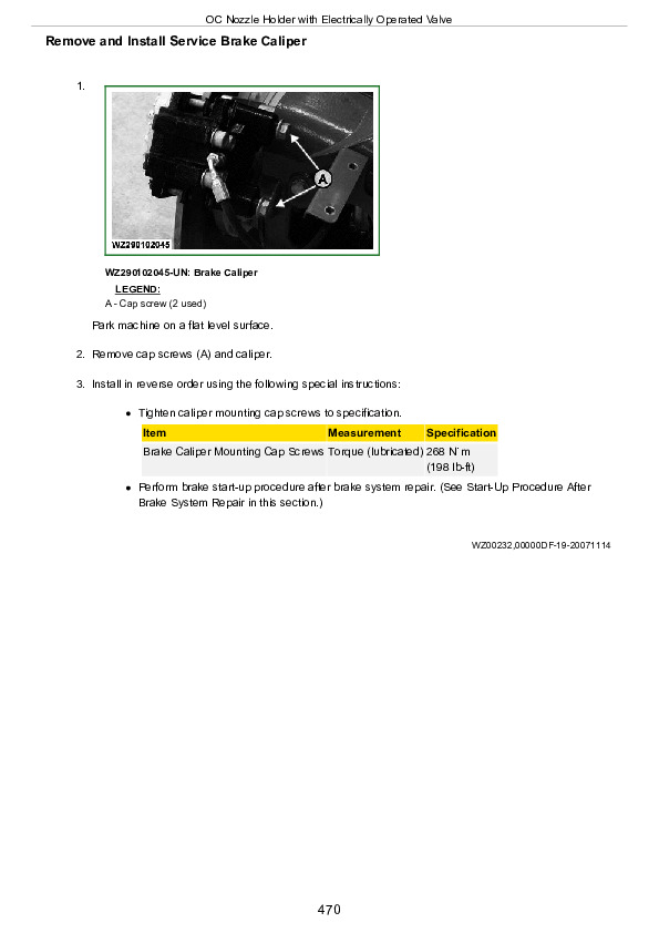
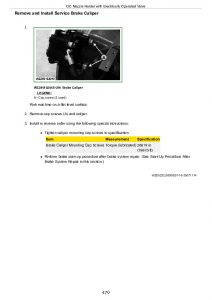
  Remove and Install Service Brake Caliper….470
  Start-Up Procedure After Brake System Repair….471
  Towing The Sprayer….472
  Bleeding Service Brakes….473
Section 95: Accessories….474
  Closed Chemical Transfer….475
  Edge Nozzles….476
  OC Nozzle Holders….478
  Hose Reel with Washing Brush and Spray Gun….480
  High Pressure Cleaner….481
  Wind Speed Sensor….483
  Drop Hoses….484
  2” Filling Hose with Strainer and Float….485
  2" Check Valve for Filling Hose….486
  Calibration Container….487
Section 100: Fuels, Lubricants and Coolants….488
  Diesel Fuel….489
  Lubricity of Diesel Fuel….490
  Handling and Storing Diesel Fuel….491
  Diesel Engine Coolant….492
  Supplemental Coolant Additives….494
  Operating in Warm Temperature Climates….495
  Additional Information About Diesel Engine Coolants and Supplemental Coolant Additives….496
  Diesel Engine Break-In Oil….498
  Diesel Engine Oil….499
  Extended Diesel Engine Oil Service Intervals….622
  Hydrostatic/Hydraulic Drive Oil….502
  Planetary Hub Oil….504
  Grease….505
  Suspension and Steering Grease….506
  Lubricant Storage….507
  Alternative and Synthetic Lubricants….508
Section 105: Lubrication and Maintenance….509
  Using High Pressure Washers….510
  Lubrication and Periodic Service….511
  General Information Regarding Condition of Vehicle….512
  Opening the Hood….513
  Access to Battery….514
  Access to Fuses….515
  Important Instructions Regarding Alternator….517
  After the First 50 Hours….518
  After the First 100 Hours….519
  As Required….520
  Service Sequences – Overview….521
  Service – Daily or Every 10 Hours….522
  Service – Once a Year….523
  Service – Every 250 Hours….524
  Service – Every 500 Hours….525
  Service – Every 1000 Hours….526
  Service – Every 2000 Hours….528
  Service – Every 3000 Hours….530
  Service – Every 6000 Hours….532
Section 106: Service – Daily or Every 10 Hours….534
  Checking the Engine Oil Level….535
  Checking Hydrostatic and Hydraulic Oil Level….536
  Checking Engine Coolant Level….537
  Checking the Fuel Filter….610
  Servicing the Fuel Tank….540
  Draining the Compressed Air Reservoir….541
  Checking Air Springs….542
  Checking Lights….543
  Lubricating Suspension Assemblies….544
  Other Service Jobs….545
Section 107: Service – Once a Year….546
  Checking Front Axle Toe-In….547
  Clean Sprayer and Coat Exposed Surfaces….549
  Inspect Service Brake Components….550
  Inspect Hydro Isolators….552
  Replace Air Drier Cartridge….553
  Inspect Seat Belt….555
  Replace Cab Air Filters….556
  Check Engine Drive Belt for Wear….557
Section 108: Service – Every 250 Hours….558
  Checking Electrolyte Level of Battery….559
  Checking the Neutral Start Circuit….560
  Checking the Wheel Retaining Nuts….561
  Checking Rocker Arm Cover Ventilation….562
  Changing Cab Air Filters….563
  Checking Air Intake Hoses….569
  Checking Engine Drive Belt for Wear….570
  Checking Oil Level in Planetary Hubs….571
  Checking Solution Tank Straps….573
  Checking Brake Operation….574
  Checking Axle Gap Adjustment….575
  Lubricating Steering Cylinder Ball Joints….577
  Lubricating Rotating Steering Arms….578
  Lubricating Boom Section Joints….579
Section 109: Service – Every 500 Hours….580
  Changing Engine Oil….581
  Changing Engine Oil Filter Element….583
  Changing the Fuel Filters….584
  Checking the Engine Ground Connection….585
  Checking the Cab Ground Connection….586
  Changing Hydrostatic and Hydraulic Filters….587
  Changing Hydraulic Oil….588
  Changing Oil in Planetary Hubs….589
Section 110: Service – Every 1000 Hours….593
  Checking Viscous Fan….594
Section 111: Service – Every 2000 Hours….595
  Checking Engine Valve Clearance….596
Section 112: Service – Every 3000 Hours (Or Every 3 Years)….597
  Changing Coolant….598
Section 113: Service – As Required….601
  Cleaning the Primary Filter Element….602
  Cleaning a Dusty Element….603
  Secondary (Safety) Element….604
  Installation….605
  Servicing the Cab Air Filters….606
  Clean Radiator and Condenser (if equipped)….607
  Checking the Fuel Filter….610
  Bleeding Air from the Fuel System….611
  Operator's Seat….612
  Prevent Battery Explosions….613
  Battery – Checking Specific Gravity….614
  Starter Motor….615
  Replacing the Drive Belt….616
  Fuses and Relais….619
Section 120: Lubrication – Booms….620
  Boom Lubrication Locations….621
  Service Intervals….622
  Tighten Boom Assembly—After First Ten Hours and Every 50 Hours….623
  Lubricate Lift Arm Pivots….624
  Lubricate Centre Section….625
  Lubricate Outer Segments….626
Section 130: Storage….628
  Clean Vehicle of Hazardous Chemicals, Including Pesticides….629
  Preparation for Storage….630
  Protection Against Frost….631
  First Activation Following Long Inactivity (Storage, Repair, Etc.)….632
Section 135: Specifications….633
  Machine Specification….634
  Metric Bolt and Screw Torque Values….638
  Unified Inch Bolt and Screw Torque Values….640
  Products to be Processed….642
  Sound Level….643
  Physical Operating Conditions….644
  Directives and Standards Applied….645
  Declaration of Conformity….646
  Combination Matrix 5430i – Part 1 (For Germany Only)….648
  Combination Matrix 5430i – Part 2 (For Germany Only)….649
  Identification Plates….650
Section IBC: John Deere Keeps You On The Job….652
  John Deere Parts….653
  The Right Tools….654
  Well-Trained Technicians….655
  Prompt Service….656

John Deere 5430i Chemical Application Vehicle with Demountable Crop Sprayer Operator’s Manual (OMWZ54301)


INSTANT DOWNLOAD


Posted on

John Deere Demountable Self-Propelled Crop Sprayers 5430i Repair Technical Manual (TM402219)


INSTANT DOWNLOAD


Complete service repair manual for John Deere Demountable Self-Propelled Crop Sprayers 5430i (PIN Prefix WZ & 1WZ), with all the shop information to maintain, repair, and rebuild like professional mechanics.

John Deere Demountable Self-Propelled Crop Sprayers 5430i workshop service & repair manual includes:
* Numbered table of contents easy to use so that you can find the information you need fast.
* Detailed sub-steps expand on repair procedure information
* Numbered instructions guide you through every repair procedure step by step.
* Notes, cautions and warnings throughout each chapter pinpoint critical information.
* Bold figure number help you quickly match illustrations with instructions.
* Detailed illustrations, drawings and photos guide you through every procedure.
* Enlarged inset helps you identify and examine parts in detail.

TM402219 English – John Deere 5430i Chemical Application Vehicle and Demountable Crop SprayerTechnical Manual (Repair).pdf
tm402228 French – Véhicule d’épandage de produits chimiques et pulvérisateur démontable 5430i Remise en état
tm402229 German – Fahrzeug 5430i zur Ausbringung von Chemikalien und abnehmbare Feldspritze – Reparatur

Total Pages: 1,029 pages
File Format: PDF (bookmarked, ToC, Searchable, Printable, high quality)
Language: English French German

ctm104 – 4.5L AND 6.8L DIESEL ENGINES (BASE ENGINE) -: (WORLDWIDE EDITION) Technical Manual
ctm320 – 4045-6068 Diesel Engine — Level 14 ECU -: (Worldwide Edition) Technical Manual
tm112219 – GreenStar™ 3 2630 Display Technical Manual
tm117919 – StarFire™ 3000 Technical Manual
tm135419 – StarFire™ 6000, 6000HA, and StarFire™ 6000 Integrated Receiver Technical Manual

MAIN SECTIONS
 Foreword
   General Information
      Safety
      General Information
      Fuels and Lubricants
   Engine
      Remove and Install Components
   Fuel, Air Intake, and Cooling Systems
      Component Removal and Installation
      Diesel Fuel System
      Engine Cooling System
   Electrical System
      Battery
      Harness and Connector Repair
      Charging Circuit
      Starting Circuit
      Fuses and Relays
      Lighting
      Chassis Control System
      Engine Control System
      Spray Rate Control System
      Boom Control System
      Cab Components
      Wiring Harness Routings
   Power Train
      Component Removal and Installation
      Hydrostatic Drive Repair
      Planetary Hub Repair
   Steering and Brakes
      Component Removal and Installation
      Steering
      Service Brakes
   Suspension and Tread Adjust
      Component Removal and Installation
      Tread Adjust Valves
      Tread Adjust Cylinders
   Hydraulic System
      Component Removal and Installation
      Hydraulic Pump
      Hydraulic Valves
      Hydraulic Reservoir
   Solution Spray System
      Component Removal and Installation
      Solution Tank
      Solution Pump
      Spray Nozzles
      Solution Control Valves
      Eductor
      Fast Fill Pump
   Pneumatic System
      Component Removal and Installation
      Component Repair
   Operator`s Station
      Cab
      Controls
      Air Conditioning System
      Heating System
      Air Suspension Seat
      Cab Door and Windshield
   Boom Repair
      Boom Repair
   Dealer Fabricated Tools

TABLE OF CONTENTS
Section 10: General Information….18
  Group 05: Safety….18
    Recognize Safety Information….22
    Understand Signal Words….23
    Perform Service Safely….24
    Wait Before Opening High-Pressure Fuel System….25
    Service Accumulator Systems Safely….26
    General Machine Operation Safety….27
    Transport in the Field and on the Road….28
    Park Machine Safely….30
    Servicing Electronic Control Units….31
    Welding Near Electronic Control Units….32
    Keep Electronic Control Unit Connectors Clean….33
    Handle Fluids Safely—Avoid Fires….34
    Prevent Battery Explosions….195
    Prepare for Emergencies….36
    Protect Against High Pressure Spray….37
    Prevent Acid Burns….38
    Wear Protective Clothing….40
    Handle Agricultural Chemicals Safely….41
    Service and Operate Chemical Sprayers Safely….43
    Avoid Contact with Agricultural Chemicals….45
    Clean Vehicle of Hazardous Pesticides….484
    Support Machine Properly….48
    Service Machines Safely….49
    Practice Safe Maintenance….50
    Avoid Harmful Asbestos Dust….52
    Work In Ventilated Area….53
    Work in Clean Area….54
    Remove Paint Before Welding or Heating….55
    Avoid Heating Near Pressurized Fluid Lines….56
    Avoid High-Pressure Fluids….57
    Service Tires Safely….58
    Service Cooling System Safely….59
    Illuminate Work Area Safely….60
    Replace Safety Signs….61
    Use Proper Lifting Equipment….62
    Use Proper Tools….63
    Construct Dealer-Made Tools Safely….64
    Decommissioning — Proper Recycling and Disposal of Fluids and Components….65
    Handle Electronic Components and Brackets Safely….66
    Live With Safety….67
  Group 10: General Information….19
    Machine Specification….72
    Machine Dimensions….76
    Face Seal Fittings Assembly and Installation—All Pressure Applications….79
    Metric Face Seal and O-Ring Stud End Fitting Torque Chart—Standard Pressures….80
    Metric Face Seal and O-Ring Stud End Fitting Torque Chart—High Pressure Applications….82
    SAE Face Seal and O-Ring Stud End Fitting Torque Chart—Standard Pressures….84
    SAE Face Seal and O-Ring Stud End Fitting Torque Chart—High Pressure Applications….86
    Four Bolt Flange Fittings Assembly and Installation—All Pressure Applications….88
    SAE Four Bolt Flange Cap Screw Torque Values—Standard Pressure Applications….89
    SAE Four Bolt Flange Cap Screw Torque Values—High Pressure Applications….90
    External Hexagon Port Plug Torque Chart….91
    Identifying Zinc-Flake Coated Fasteners….93
    Metric Bolt and Screw Torque Values….94
    Unified Inch Bolt and Screw Torque Values….96
    Programming Control Units….98
    Preparing and Painting Sprayer Components….101
  Group 15: Fuels and Lubricants….19
    Diesel Fuel….104
    Handling and Storing Diesel Fuel….106
    Lubricity of Diesel Fuel….107
    Diesel Engine Coolant (engine with wet sleeve cylinder liners)….108
    Testing Diesel Engine Coolant….110
    Supplemental Coolant Additives….111
    Operating in Warm Temperature Climates….112
    Additional Information About Diesel Engine Coolants and John Deere LIQUID COOLANT CONDITIONER….113
    Diesel Engine Break-In Oil — Non-Emissions Certified and Certified Tier 1, Tier 2, Tier 3, Stage I, Stage II, and Stage III….115
    Diesel Engine Oil — Non-Emissions Certified and Certified Tier 1 and Stage I….117
    Extended Diesel Engine Oil Service Intervals — Non-Emissions Certified and Certified Tier 1 and Stage I….119
    Hydrostatic/Hydraulic Drive Oil….120
    Planetary Hub Oil….121
    Grease….122
    Suspension and Steering Grease….123
    Alternative and Synthetic Lubricants….124
    Lubricant Storage….125
Section 20: Engine….126
  Group 00: Remove and Install Components….126
    Essential or Recommended Tools….993
    Specifications….1087
    John Deere Engine Repair—Use CTM….371
    Clean Vehicle of Hazardous Pesticides….484
    Remove and Install Engine….132
    Remove and Install Hood….141
    Remove and Install Exhaust System….142
Section 30: Fuel, Air Intake, and Cooling Systems….144
  Group 00: Component Removal and Installation….144
    Specifications….1087
    Remove and Install Air Cleaner Housing….147
    Remove and Install Fan Drive and Shroud….148
    Remove and Install Radiator….152
    Remove and Install Aftercooler….166
    Remove and Install Diesel Fuel Cooler….169
    Remove and Install Expansion Tank….170
    Remove and Install Fuel Tank….174
  Group 05: Diesel Fuel System….144
    Specifications….1087
    Clean and Inspect Fuel Tank….179
    Replace Fuel Filter, Fuel Pump, and Bleed Fuel System….180
  Group 10: Engine Cooling System….144
    Specifications….1087
    Drain, Flush, and Fill Cooling System….183
    Test Radiator and Coolant Tank Cap….186
Section 40: Electrical System….188
  Group 05: Battery….188
    Essential or Recommended Tools….993
    Specifications….1087
    Prevent Battery Explosions….195
    Battery Safety….196
    Prevent Damage to Electrical Systems….198
    Check Electrolyte Specific Gravity….199
    Charging Batteries….201
    Connecting Battery Cables….203
    Battery Replacement….204
  Group 10: Harness and Connector Repair….188
    Essential or Recommended Tools….993
    Other Material….1022
    Use Electrical Insulating Compound….216
    Using High-Pressure Washers….217
    Electrical System Visual Inspection….218
    Basic Electrical Component Handling / Precautions for Vehicles Equipped with Computer Controlled Systems….219
    Electrical Connector / Wiring Harness Handling and Repair….220
    Installation of Repair Wire Assembly (RWA)….221
    Repair Procedure R-A….230
    Repair Procedure R-B….235
    Repair Procedure R-C….239
    Repair Procedure R-D….244
    Repair Procedure R-E….247
    Repair Procedure R-F….251
    Repair Procedure R-G….255
    Repair Procedure R-I….258
    Repair Procedure R-J….261
    Repair Procedure R-K….266
    Repair Procedure R-M….269
    Repair Procedure R-N….273
    Repair Procedure R-AA….277
    Repair Procedure R-AE….278
    Repair Procedure R-AF….283
    Repair Procedure R-AG….286
    Repair Procedure R-AH….289
    Repair Procedure R-AI….291
    Repair Procedure R-AJ….294
    Repair Procedure R-AK….299
    Repair Procedure R-AL….302
    Repair Procedure R-AM….306
    Repair Procedure R-AN….309
    Repair Procedure R-AO….312
    Repair Procedure R-AP….315
    Repair Procedure R-AQ….318
  Group 15: Charging Circuit….189
    Specifications….1087
    Remove and Install Alternator….323
  Group 20: Starting Circuit….189
    Essential or Recommended Tools….993
    Remove and Install Starter Motor….327
    John Deere Starting Motor Repair—Use CTM….328
  Group 25: Fuses and Relays….189
    Replace Fuses and Relays….334
  Group 30: Lighting….189
    Safety Rules When Replacing Halogen Bulbs….340
    Safety Instructions for Replacing a Halogen Bulb….341
    Safety Instructions for Replacing Xenon (HID) Bulbs and Ballast Units….343
    Hood Headlight Bulb Replacement and Adjustment….345
    Remove and Install Headlight Assembly….349
    Handling HID Light Bulbs Safely….350
    Replacing Road Light Bulbs….351
    Replace Roof Flood Light Halogen Bulb….354
    Replace Rear Warning Light Bulbs….356
    Replace Extremity Front Warning Light Bulb….357
    Replacing Xenon (HID) Worklights and Ballast Units….359
  Group 35: Chassis Control System….190
    Specifications….1087
    Replace Hydraulic Oil Temperature Sensor….363
    Replace Wheel Speed Sensor….365
    Replace Fuel Level Sender….366
    Replace Chassis Control Unit (CCU) and Steering System Control Unit (SSU)….368
  Group 40: Engine Control System….190
    John Deere Engine Repair—Use CTM….371
  Group 45: Spray Rate Control System….190
    Specifications….1087
    Remove and Install Auxiliary Fill Pressure Sensor….374
    Remove and Install Solution Pressure Sensor….375
    Remove and Install Spray Rate Control Unit….376
    Remove and Install Solution Command System Electronic Power Module….378
    Remove, Adjust, and Install Solution Pump Hydraulic Motor Speed Sensor….380
  Group 50: Boom Control System….190
    Remove and Install BoomTrac Sensor (If Equipped)….383
    Replace Boom Hydraulic Control Unit (BHC)….384
    Remove and Install Boom Inner Fold Position Sensor….385
    Remove and Install Boom Outer Fold Position Switch….386
    Remove and Install Pendulum Lock Position Sensor….387
    Remove and Install Boom Tilt Sensor….388
    Remove and Install Boom Height Sensor….389
  Group 55: Cab Components….190
    Specifications….1087
    Decontaminate Spray Equipment….392
    Remove and Install Boom Select Switch….393
    Remove and Install Steering Mode Switch….394
    Remove and Install Emergency Brake Control Switch….395
    Remove and Install Key Switch….397
    Remove and Install Light and Wiper Switch….398
    Remove and Install Turn Signal Switch….399
    Replace Horn Switch….400
    Remove and Install Armrest Control Unit (ACU)….401
    Remove and Install Throttle Control….402
    Remove and Install Throttle Sensor….404
    Remove and Install Multi-Function Lever Position Harness….406
    Remove and Install Armrest Rocker Switches….410
    Remove and Install Tread Adjust Switch….411
    Replace Air Conditioning System On/Off Switch….412
    Replace Blower Control Switch….413
    Replace Dome Light….414
    Replace Air Conditioning High/Low Pressure Switch….416
    Replace Wiper Motor….418
    Replace Windshield Washer Pump….420
    Remove and Install Radio….421
    Replace Speakers….422
    Replace Antenna….423
    Remove and Install Air Conditioning Temperature Control Switch….427
  Group 60: Wiring Harness Routings….191
    Engine Harness Routing….432
    Chassis Harness Routing….434
    Hood Harness Routing….436
    Cab Harness Routing….437
    Center Boom Harness Routing….439
    Outer Boom Harness Routing….441
Section 50: Power Train….442
  Group 00: Component Removal and Installation….442
    Essential or Recommended Tools….993
    Specifications….1087
    Remove and Install Hydrostatic Drive Motor….447
    Remove and Install Rear Tandem Drive Pump….451
    Remove and Install Front Tandem Drive Pump….460
    Remove and Install Planetary Hub….468
    Remove, Install, and Adjust Hydrostatic Control Cable….473
  Group 05: Hydrostatic Drive Repair….442
    Essential or Recommended Tools….993
    Service Equipment and Tools….958
    Other Material….1022
    Specifications….1087
    Clean Vehicle of Hazardous Pesticides….484
    Start-Up Procedure After Hydrostatic Repair….485
    Flush Hydrostatic Drive System….488
    Remove and Install Hydrostatic Pump Shaft Seal….490
    Replace Hydrostatic Pump Cartridge Valves….494
    Replace Hydrostatic Pump Charge Pressure Relief Valve….495
    Repair Charge Pump….496
    Remove and Install Hydrostatic Pump Control Valve….503
    Remove and Install Control Valve Neutral Start Switch….509
    Adjust Neutral Start Switch….511
    Adjust Control Valve Eccentric Plug….514
    Disassemble Hydrostatic Drive Pump….517
    Inspect and Repair Hydrostatic Drive Pump….523
    Assemble Hydrostatic Drive Pump….527
    Disassemble and Assemble Hydrostatic Drive Motor….537
    Disassemble and Assemble Hydrostatic Drive Motor Port Plate….549
  Group 10: Planetary Hub Repair….442
    Essential or Recommended Tools….993
    Service Equipment and Tools….958
    Other Material….1022
    Specifications….1087
    Disassemble Planetary Hub….559
    Assemble Planetary Hub….573
Section 60: Steering and Brakes….594
  Group 00: Component Removal and Installation….594
    Other Material….1022
    Specifications….1087
    Remove and Install Steering Wheel….598
    Remove and Install Steering Column….600
    Remove and Install Steering Valve….602
    Remove and Install Steering Input Device (SID) Sensor….605
    Remove and Install Steering Cylinder….607
    Remove and Install AutoTracTM SSU Control Unit….594
    Remove, Adjust, and Install AutoTrac Wheel Angle Sensor….610
    Remove and Install Service Brake Valve….614
    Remove and Install Service Brake Caliper….617
    Remove and Install Trailer Brake Valve….620
    Remove and Install AutoTrac Valve….622
    Remove and Install Emergency Steering Pump….624
  Group 05: Steering….594
    Other Material….1022
    Specifications….1087
    Repair Steering Cylinder….630
    Bleed Steering System….632
    Rear Wheel Adjustment….633
  Group 10: Service Brakes….594
    Specifications….1087
    Inspect Service Brake System Components….643
    Disassemble and Assemble Service Brake Caliper….645
    Start-Up Procedure After Brake System Repair….647
Section 61: Suspension and Tread Adjust….648
  Group 00: Component Removal and Installation….648
    Essential or Recommended Tools….993
    Other Material….1022
    Specifications….1087
    Remove and Install Air Spring Leveling System Control Valve….653
    Remove and Install Leveling System Unloader Valve Switch….655
    Remove and Install Air Spring Assemblies….656
    Remove and Install Tread Adjust Valve Block….686
    Remove and Install Hydraulic Tread Adjust Cylinders….661
    Replace Tread Adjust Shim Pads….665
    Replace Suspension Bushings and Seals….669
  Group 05: Tread Adjust Valves….648
    Essential or Recommended Tools….993
    Specifications….1087
    Service Parts Kit….685
    Tread Adjust Valve Block….686
    Replace Control Valve Coil(s)….687
    Replace Tread Adjust Valve….690
    Remove, Inspect, and Install Manifold Check Valve and Pilot Piston….692
  Group 10: Tread Adjust Cylinders….648
    Specifications….1087
    Disassemble and Assemble Tread Adjust Cylinders….696
Section 70: Hydraulic System….698
  Group 00: Component Removal and Installation….698
    Essential or Recommended Tools….993
    Specifications….1087
    Remove and Install Auxiliary Drive Pump….703
    Remove and Install Auxiliary Hydraulic Oil Cooler….707
    Remove and Install Auxiliary Hydraulic Oil Cooler Fan….711
    Remove and Install Hydraulic Oil Heat Exchanger….713
    Remove and Install Priority Valve….715
    Remove and Install Solution Pump Hydraulic Motor….717
    Remove and Install Pressure Washer Hydraulic Valve….721
    Remove and Install Hydraulic Reservoir….723
    Remove and Install Hydraulic Pump Compensator Valve….731
    Remove and Install Four-Wheel Steer Valve….733
    Remove and Install Toe Control Valve….735
    Remove and Install Combination Valve….737
    Remove and Install Boom Control Valve Block….739
    Remove and Install Boom Lift Cylinders….741
    Remove and Install Variable Geometry Cylinder….743
    Remove and Install Boom Inner Fold Cylinder….745
    Remove and Install Boom Outer Fold Cylinder….747
    Remove and Install Boom Tilt Cylinder….749
    Remove and Install Pendulum Lock Cylinder….751
    Remove and Install Accumulator….753
    Remove and Install Attenuator….755
    Remove and Install Ladder Cylinder….757
    Remove and Install Ladder Control Valve….759
  Group 05: Hydraulic Pump….698
    Relieve Hydraulic System Pressure….764
    Disassemble and Assemble Auxiliary Drive Pump….767
  Group 10: Hydraulic Valves….698
    Essential or Recommended Tools….993
    Specifications….1087
    Boom Control Valve General Information….774
    Boom Control Valve Solenoid Identification….775
    Disassemble, Inspect, and Assemble Boom Control Valve….776
    Disassemble, Inspect, and Assemble Priority Valve….780
    Disassemble and Assemble Four-Wheel Steer Valve….783
    Disassemble and Assemble Combination Valve….785
  Group 15: Hydraulic Reservoir….699
    Specifications….1087
    Clean Hydraulic Reservoir Strainers….789
Section 80: Solution Spray System….792
  Group 00: Component Removal and Installation….792
    Other Material….1022
    Specifications….1087
    Cleaning the Machine….798
    Processing Residual Liquids….800
    Auto Dilution (SCS)….801
    Draining Solution Tank….803
    Remove and Install Chemical Transport Compartment….805
    Remove and Install Eductor System Venturi….807
    Remove and Install Fast Fill Pump and Motor….810
    Remove and Install Hand Wash Tank….818
    Remove and Install Pneumatic Spray Nozzle Shut-Off Valve….820
    Remove and Install Solution Valve Actuator….821
    Solution Valve Actuator Locations….822
    Remove and Install Solution Pressure Relief Valves….824
    Remove and Install Solution Tank….826
    Remove and Install Solution Tank Transfer Valve Assembly….832
    Remove and Install Solution Pump….834
    Remove and Install Suction Strainer Assembly….839
    Remove and Install Pressure Strainer Assembly….841
    Remove and Install Nozzle Holder (5-Way)….842
    Remove and Install Spray Nozzle Air Valve….844
    Remove and Install Nozzle Holder (Off-Center Nozzle)….845
    Remove and Install Spray Nozzle Solenoid (Edge Nozzle)….847
    Remove and Install Agitation Pressure Regulator….849
    Remove and Install Flowmeter Assembly….851
    Remove and Install Flowmeter Sensor….852
    Replace Flowmeter Insert….853
    Remove and Install Spray Line Valve….855
    Remove and Install Rinse Tank….857
    Remove and Install Pressure Washer Pump and Motor….866
    Remove and Install Pressure Washer Hydraulic Motor….868
  Group 05: Solution Tank….793
    Repair Polyethylene Plastic….875
  Group 10: Solution Pump….793
    Other Material….1022
    Specifications….1087
    Disassemble and Assemble Solution Pump….883
    Remove and Install Pump Oil Seal….903
    Disassemble and Assemble Pump Accumulator….906
  Group 15: Spray Nozzles….793
    Disassemble and Assemble Nozzle Holder (5-Way)….910
    Disassemble and Assemble Nozzle Holder (Single)….912
    Disassemble and Assemble Spray Nozzle Air Valve….914
  Group 20: Solution Control Valves….793
    Essential or Recommended Tools….993
    Specifications….1087
    Disassemble and Assemble Fittings….918
    Disassemble and Assemble Check Valve….920
    Disassemble and Assemble Spray Line Valve….921
    Disassemble and Assemble Agitation Pressure Regulator….923
    Disassemble Solution Valves….925
    Assemble Spray Rate Regulator Valve….930
    Assemble 2- and 3-Way Valve….935
    Assemble Pressure Recirculation Valve….939
    Adjust 2-Way, 3-Way, and Pressure Recirculation Valve Actuators….943
    Adjust Spray Rate Regulator Actuator….946
  Group 25: Eductor….793
    Eductor Assembly—Exploded View….953
  Group 30: Fast Fill Pump….793
    Service Equipment and Tools….958
    Specifications….1087
    Fast Fill Pump—Exploded View….960
    Disassemble and Assemble Fast Fill Pump….961
    Disassemble and Assemble Fast Fill Pump Motor….967
Section 81: Pneumatic System….974
  Group 00: Component Removal and Installation….974
    Remove and Install On Board Air Compressor….977
    Remove and Install On Board Air Reservoir….979
    Remove and Install On Board Air Dryer….981
  Group 05: Component Repair….974
    Specifications….1087
    Pneumatic Fittings….985
    Disassemble and Assemble On Board Air Dryer….986
Section 90: Operator's Station….990
  Group 05: Cab….990
    Essential or Recommended Tools….993
    Specifications….1087
    Remove and Install Cowl….995
    Remove, Inspect, and Install Cab Interior Recirculating Air Filters….997
    Remove, Inspect, and Install Exterior Cab Intake Air Filters….999
    Remove and Install Headliner….1001
    Remove and Install Cab Roof….1003
    Remove and Install Fender Console….1007
    Remove and Install Cab….1010
  Group 10: Controls….990
    Other Material….1022
    Specifications….1087
    Remove and Install Armrest….1024
    Remove and Install Armrest Control Cover….1026
    Remove and Install Multi-Function Lever….1028
  Group 15: Air Conditioning System….990
    Special Tools….1032
    Specifications….1087
    Torques for Tightening Refrigerant Hoses….1036
    Safety At Work….1037
    Handling Refrigerant….1038
    In an Emergency….1039
    Safety Equipment….1040
    Storage of Refrigerant Containers….1041
    R134A Refrigerant….1042
    Air-Conditioning System – Safety at Work….1043
    Air-Conditioning – Important….1045
    Service Work on Air Conditioning System….1046
    Discharge the System….1049
    Evacuate the System….1051
    Fill with Refrigerant Oil….1052
    Instructions for Starting Up the DENSO Air-Conditioning Compressor….1054
    Charge the System….1055
    Leakage Test….1057
    Remove and Install Compressor….1058
    Checking Level in the Compressor….1060
    Disassemble Compressor Clutch….1061
    Checking Clutch Hub Clearance….1063
    Checking the Compressor Manifold….1064
    Remove and Install Condenser….1065
    Replace Receiver-Drier….1067
    Remove and Install the Evaporator and Expansion Valve….1069
    Arrangement of Condensation Water Drain Hoses….1072
  Group 20: Heating System….991
    Remove and Install Heater Core….1075
    Remove and Install Fan Motor Resistors….1077
    Remove and Install Fan Motors….1079
    Remove and Install Heater Valve….1081
    Adjust Heater Valve Control Cable….1083
  Group 25: Air Suspension Seat….991
    Remove and Install Seat and Suspension….1085
  Group 30: Cab Door and Windshield….991
    Specifications….1087
    Repair Cab Door Latch Assembly….1088
    Cab Door Lock Adjustment….1090
    Replace Windshield Glass or Seal….1092
    Remove and Install Rear Window….1094
    Remove and Install Front Lower Windows….1095
    Remove and Install Side Windows….1096
    Remove and Install Cab Doors….1098
    Remove and Install Safety Exit Door….1103
Section 100: Boom Repair….1104
  Group 05: Boom Repair….1104
    Remove and Install Boom Shock Absorbers….1106
    Remove and Install Spray Boom Suspension Springs….1107
    Remove and Install Yaw Rocker Bumpers….1108
Section 199: Dealer Fabricated Tools….1112
  Group 05: Dealer Fabricated Tools….1112
    DFN21 Pump Support Fixture….1114
    DFNX65-A1 Eccentric Plug Adjustment Tool….1115
    DFNX65-A2 Sizing Arbor….1116
    DFNXT12—Front and Rear Tandem Pump Removal Tool….1117
    DFNXT14—Spindle Driver….1118
    
John Deere Demountable Self-Propelled Crop Sprayers 5430i Repair Technical Manual (TM402219)


INSTANT DOWNLOAD


Posted on

John Deere Model 5430i Demountable Self-Propelled Crop Sprayers Diagnosis and Tests Service Manual (TM402319)


INSTANT DOWNLOAD


Complete Diagnosis and Tests manual with Electrical Wiring Diagrams for John Deere Demountable Self-Propelled Crop Sprayers 5430i (PIN Prefix WZ & 1WZ), with all the workshop information to maintain, diagnose, and rebuild like professional mechanics.

John Deere Demountable Self-Propelled Crop Sprayers 5430i workshop diagnostics manual includes:
* Numbered table of contents easy to use so that you can find the information you need fast.
* Detailed sub-steps expand on repair procedure information
* Numbered instructions guide you through every repair procedure step by step.
* Troubleshooting and electrical service procedures are combined with detailed wiring diagrams for ease of use.
* Notes, cautions and warnings throughout each chapter pinpoint critical information.
* Bold figure number help you quickly match illustrations with instructions.
* Detailed illustrations, drawings and photos guide you through every procedure.
* Enlarged inset helps you identify and examine parts in detail.

TM402319 English – John Deere 5430i Demountable Self-Propelled Crop Sprayer Technical Manual (Operation and Test).PDF
tm402328 French – Véhicule d’épandage de produits chimiques et pulvérisateur démontable 5430i – Diagnostics et contrôles.pdf
tm402329 German – Fahrzeug 5430i zur Ausbringung von Chemikalien und abnehmbare Feldspritze – Diagnose und Prüfungen.pdf

Total Pages: 2,911 pages
File Format: PDF (bookmarked, ToC, Searchable, Printable, high quality)
Language: English French German

ctm104 – 4.5L AND 6.8L DIESEL ENGINES (BASE ENGINE) -: (WORLDWIDE EDITION) Technical Manual
ctm320 – 4045-6068 Diesel Engine — Level 14 ECU -: (Worldwide Edition) Technical Manual
tm112219 – GreenStar™ 3 2630 Display Technical Manual
tm117919 – StarFire™ 3000 Technical Manual
tm135419 – StarFire™ 6000, 6000HA, and StarFire™ 6000 Integrated Receiver Technical Manual

MAIN SECTIONS
 Diagnostic Trouble Codes (DTC)
   Observable Symptoms
      Engine
      Air Intake and Cooling
      Electrical System
      Power Train
      Brakes
      Hydraulics
      Tread Adjust
      Steering
      Cab – Air Conditioning and Heating
      Pneumatic System
   Engine
   Air Intake and Cooling Systems
   Electrical System
      Electrical Schematics Overview
      Accessing Diagnostic Codes and Addresses
      Diagnostic Addresses
      GS2 Display Diagnostic Information
      Air Seat
      Air Conditioning and Heating
      Air Filter Restriction
      Auxiliary Power
      Boom Fold/Unfold
      Boom Raise and Lower
      Boom Return to Height
      Boom Tilt
      BoomTrac – Automatic Boom Leveling
      Boom Variable Geometry
      CAN Bus
      Charging
      Dome Light
      Electric Fuel Pump
      Engine and Fuel Control
      Engine Sensors
      Fuel Level Sensor
      GreenStar Display
      GreenStar GPS Receiver
      Horn
      Hydraulic Oil Cooler Fan
      Hydraulic Oil Temperature
      Hydrostatic Boost
      Ladder Electrical
      Lights
      Multi-Function Lever
      Multi-Function Lever Position
      Operator Presence Switch
      Park (Secondary) Brake
      Power Supply
      Power Mirror
      Radio
      Slip Control
      Solution Control System
      Solution Pressure System
      Solution Pump Oil Level
      Solution Pump Speed
      Solution Quick Fill System
      Solution Tank Level
      Solution Transfer System
      Speed Range
      Spray Valve Control
      Starting Aid (Glow Plugs)
      Starting System
      AutoTrac Steering
      Steering – Four-Wheel Steering
      Steering – Secondary
      Throttle
      Trailer Brake
      Tread Adjust
      Wheel Speed Sensor
      Wiper
      Connector Information
   Power Train
   Brakes
   Hydraulic System
      Boom Fold Hydraulic System
      Boom Raise Hydraulic System
      Boom Tilt Hydraulic System
      Boom Variable Geometry Hydraulic System
      Diaphragm Solution Pump Hydraulic System
      Ladder Hydraulic System
      Pressure Washer Hydraulic
      Quick Fill Pump Motor Hydraulic System
   Tread Adjust System
   Steering System
   Operator`s Cab
   Solution System
   Pneumatic System
   Service Tools

TABLE OF CONTENTS…1
Section 210: General Information…59
  Group 05: Safety…59
    Recognize Safety Information…62
    Understand Signal Words…63
    Perform Service Safely…64
    Wait Before Opening High-Pressure Fuel System…65
    Service Accumulator Systems Safely…66
    Handle Fluids Safely—Avoid Fires…67
    Prevent Battery Explosions…68
    Prepare for Emergencies…69
    Protect Against High Pressure Spray…70
    Prevent Acid Burns…71
    Wear Protective Clothing…73
    Handle Agricultural Chemicals Safely…74
    Service and Operate Chemical Sprayers Safely…76
    Avoid Contact with Agricultural Chemicals…78
    Clean Vehicle of Hazardous Pesticides…80
    Support Machine Properly…81
    Service Machines Safely…82
    Practice Safe Maintenance…83
    Avoid Harmful Asbestos Dust…85
    Work In Ventilated Area…86
    Work in Clean Area…87
    Remove Paint Before Welding or Heating…88
    Avoid Heating Near Pressurized Fluid Lines…89
    Avoid High-Pressure Fluids…90
    Service Tires Safely…91
    Service Cooling System Safely…718
    Illuminate Work Area Safely…93
    Replace Safety Signs…94
    Use Proper Lifting Equipment…95
    Use Proper Tools…96
    Construct Dealer-Made Tools Safely…97
    Decommissioning — Proper Recycling and Disposal of Fluids and Components…719
    Live With Safety…99
  Group 10: General References…60
    General Information – Inch Bolt and Cap Screws, Torque Values…102
    General Information – Metric Bolt and Cap Screws, Torque Values…104
    General Information – Hydraulic System Inch Fittings, Torque Values…106
    General Information – Hydraulic System Metric Fittings, Torque Values…107
    General Information – Electrical System, Component Identification Table…109
    General Information – Electrical System, How to Read a Diagnostic Schematic…111
    General Information – Electrical System, Symbols in Schematic, Wiring and Harness Diagrams…113
    General Information – Electrical System, Troubleshooting Unsolved Problems…115
    General Information – Electrical System, Worksheet for Circuit/Harness Test…116
    General Information – Electrical System, Visual Check…118
    General Information – Electrical System, Electrical Circuit Malfunctions…119
    General Information – Electrical System, Seven-Step Test Procedure…124
    General Information – Hydraulic System, Symbols in Circuit Diagrams…126
Section 211: Diagnostic Trouble Codes (DTC)…132
  Group 5A: ECU – Control Unit…132
    ECU 000091.09 – Accelerator Pedal Position…132
    ECU 000094.03 – Engine Fuel Delivery Pressure…132
    ECU 000094.04 – Engine Fuel Delivery Pressure…132
    ECU 000094.10 – Engine Fuel Delivery Pressure…132
    ECU 000094.17 – Engine Fuel Delivery Pressure…132
    ECU 000097.03 – Water-in-Fuel Sensor Signal Voltage Too High…132
    ECU 000097.04 – Water-in-Fuel Sensor Signal Voltage Too Low…132
    ECU 000097.16 – Water In Fuel Detected…132
    ECU 000100.01 – Engine Oil Pressure Extremely Low…132
    ECU 000100.04 – Engine Oil Pressure…132
    ECU 000105.03 – Engine Intake Manifold 1 Temperature…132
    ECU 000105.04 – Engine Intake Manifold 1 Temperature…132
    ECU 000105.16 – Engine Intake Manifold 1 Temperature…132
    ECU 000107.00 – Air Cleaner Restriction…132
    ECU 000110.00 – Engine Coolant Temperature Extremely High…132
    ECU 000110.03 – Engine Coolant Temperature Sensor Input Voltage Too High…132
    ECU 000110.04 – Engine Coolant Temperature Sensor Input Voltage Too Low…132
    ECU 000110.15 – Engine Coolant Temperature Slightly High…132
    ECU 000110.16 – Engine Coolant Temperature Moderately High…132
    ECU 000157.03 – Fuel Rail Pressure Sensor Input Voltage Too High…132
    ECU 000158.17 – Key Switch Battery Potential…132
    ECU 000174.03 – Fuel Temperature Sensor Input Voltage Too High…132
    ECU 000174.04 – Fuel Temperature Sensor Input Voltage Too Low…132
    ECU 000174.16 – Fuel Temperature Moderately High…132
    ECU 000190.00 – Engine Overspeed Extreme…132
    ECU 000611.03 – Electronic Injector Wiring Shorted To Power Source…132
    ECU 000611.04 – Electronic Injector Wiring Shorted To Ground…132
    ECU 000620.03 – 5 Volts DC Supply (obsolete)…132
    ECU 000620.04 – 5 Volts DC Supply (obsolete)…132
    ECU 000627.01 – Power Supply (Obsolete)…132
    ECU 000636.02 – Pump Position Sensor Input Noise…132
    ECU 000636.08 – Pump Position Sensor Input Missing…133
    ECU 000636.10 – Pump Position Sensor Input Pattern Error…133
    ECU 000637.02 – Crank Sensor Input Noise…133
    ECU 000637.07 – Crank Position/Pump Position Timing Moderately Out of Sync…133
    ECU 000637.08 – Crank Sensor Signal Input Missing…133
    ECU 000637.10 – Crank Sensor Input Pattern Error…133
    ECU 000651.02 – Cylinder No.1 Electronic Injector Part Number Invalid…133
    ECU 000651.05 – Cylinder No.1 Electronic Injector Circuit Open…133
    ECU 000651.06 – Cylinder No.1 Electronic Injector Circuit Shorted…133
    ECU 000651.07 – Cylinder No.1 Electronic Injector Mechanical Failure…133
    ECU 000652.02 – Cylinder No.2 Electronic Injector Part Number Invalid…133
    ECU 000652.05 – Cylinder No.2 Electronic Injector Circuit Open…133
    ECU 000652.06 – Cylinder No.2 Electronic Injector Circuit Shorted…133
    ECU 000652.07 – Cylinder No.2 Electronic Injector Mechanical Failure…133
    ECU 000653.05 – Cylinder No.3 Electronic Injector Circuit Open…133
    ECU 000653.06 – Cylinder No.3 Electronic Injector Circuit Shorted…133
    ECU 000653.07 – Cylinder No.3 Electronic Injector Mechanical Failure…133
    ECU 000654.05 – Cylinder No.4 Electronic Injector Circuit Open…133
    ECU 000654.06 – Cylinder No.4 Electronic Injector Circuit Shorted…133
    ECU 000654.07 – Cylinder No.4 Electronic Injector Mechanical Failure…133
    ECU 000654.13 – Cylinder No.4 Electronic Injector QR Code Invalid…133
    ECU 000655.05 – Cylinder No.5 Electronic Injector Circuit Open…133
    ECU 000655.06 – Cylinder No.5 Electronic Injector Circuit Shorted…133
    ECU 000655.07 – Cylinder No.5 Electronic Injector Mechanical Failure…133
    ECU 000656.05 – Cylinder No.6 Electronic Injector Circuit Open…133
    ECU 000656.06 – Cylinder No.6 Electronic Injector Circuit Shorted…133
    ECU 000656.07 – Engine Injector Cylinder #06…133
    ECU 001080.03 – (Obsolete) Sensor Supply Voltage 2 (+5V DC)…133
    ECU 001080.04 – (Obsolete) Sensor Supply Voltage 2 (+5V DC)…133
    ECU 001347.05 – Suction Control Valve Current Mismatch…133
    ECU 001347.07 – Fuel Rail Pressure Control Error…133
    ECU 001347.10 – Engine Fuel Pump Pressurizing Assembly…133
    ECU 001348.05 – Engine Fuel Pump Pressurizing Assembly #2…133
    ECU 001348.10 – Engine Fuel Pump Pressurizing Assembly #2…134
    ECU 001569.31 – Fuel Derate…134
    ECU 001638.00 – Hydraulic Temperature…134
    ECU 001638.03 – Hydraulic Temperature…134
    ECU 001638.04 – Hydraulic Temperature…134
    ECU 001638.16 – Hydraulic Temperature…134
    ECU 002580.03 – Hydraulic Brake Pressure Circuit…134
    ECU 002580.04 – Hydraulic Brake Pressure Circuit…134
    ECU 523319.18 – ECU Power Supply Voltage – Switched…134
  Group 5B: BHC – Boom Hydraulic Control Unit…134
    BHC 000158.00 – System Voltage High…134
    BHC 000158.01 – System Voltage Low…134
    BHC 000237.02 – Vehicle Identification Number Mismatch…134
    BHC 000237.14 – Vehicle Identification Number Disabled…134
    BHC 000237.31 – Vehicle Identification Number Not Available…134
    BHC 000630.02 – Calibration Memory Data Incorrect…134
    BHC 002071.09 – CCU Message Missing…134
    BHC 002170.09 – BHC Sensor Missing…134
    BHC 320501.13 – Boom Slide Level Sensor Faults…134
    BHC 320502.05 – Roll Lock-Out Hold Valve Failure…134
    BHC 320502.06 – Roll Lock-Out Hold Valve Failure…134
    BHC 520300.02 – BoomTrac Sensing Left…134
    BHC 520301.02 – BoomTrac Sensing Right…134
    BHC 522316.03 – Boom Height Sensor Out Of Range High…134
    BHC 522316.04 – Boom Height Sensor Out Of Range Low…134
    BHC 522316.13 – Boom Height Sensor Out Of Calibration…134
    BHC 522372.03 – Right Inner Sensor Out Of Range High…134
    BHC 522372.04 – Right Inner Sensor Out Of Range Low…134
    BHC 522372.13 – Right Inner Sensor Out Of Calibration…134
    BHC 522378.03 – Left Inner Sensor Out Of Range High…134
    BHC 522378.04 – Left Inner Sensor Out Of Range Low…134
    BHC 522378.13 – Left Inner Sensor Out Of Calibration…134
    BHC 523460.03 – Roll Lock Sensor Out Of Range High…134
    BHC 523460.04 – Roll Lock Sensor Out Of Range Low…135
    BHC 523460.13 – Roll Lock Sensor Out Of Calibration…135
    BHC 523461.03 – Roll Bias Sensor Out Of Range High…135
    BHC 523461.04 – Roll Bias Sensor Out Of Range Low…135
    BHC 523461.13 – Roll Bias Sensor Out Of Calibration…135
    BHC 523463.05 – Roll Bias Left Current Below Normal…135
    BHC 523463.06 – Roll Bias Left Current Above Normal…135
    BHC 523464.05 – Roll Bias Right Current Below Normal…135
    BHC 523464.06 – Roll Bias Right Current Above Normal…135
    BHC 523465.14 – Boom Unfold Left Outer…135
    BHC 523466.14 – Boom Fold Left Outer…135
    BHC 523467.14 – Boom Fold Left Inner…135
    BHC 523468.14 – Boom Unfold Left Inner…135
    BHC 523469.14 – Boom Unfold Right Inner…135
    BHC 523470.14 – Boom Fold Right Inner…135
    BHC 523471.14 – Boom Fold Right Outer…135
    BHC 523472.14 – Boom Unfold Right Outer…135
    BHC 523477.05 – Center Frame Lower Current Below Normal…135
    BHC 523477.06 – Center Frame Lower Current Above Normal…135
    BHC 523478.05 – Center Frame Raise Current Below Normal…135
    BHC 523478.06 – Center Frame Raise Mode Short to Power…135
    BHC 523479.05 – Left Variable Geometry Down Current Below Normal…135
    BHC 523479.06 – Left Variable Geometry Down Current Above Normal…135
    BHC 523480.05 – Right Variable Geometry Down Current Below Normal…135
    BHC 523480.06 – Right Variable Geometry Down Current Above Normal…135
    BHC 523481.05 – Left Variable Geometry Up Current Below Normal…135
    BHC 523481.06 – Left Variable Geometry Up Current Above Normal…135
    BHC 523482.05 – Right Variable Geometry Up Current Below Normal…135
    BHC 523482.06 – Right Variable Geometry Up Current Above Normal…135
  Group 5C: CLC – Control Unit…135
    CLC 000158.00 – High System Voltage…135
    CLC 000158.01 – Low System Voltage…135
    CLC 000158.17 – Low System Voltage…135
    CLC 000158.18 – Key Switch Battery Potential…136
    CLC 000628.02 – Program Memory…136
    CLC 000628.12 – Program Memory…136
    CLC 000629.11 – Control Unit…136
    CLC 000629.12 – Control Unit…136
    CLC 000630.02 – Calibration Memory…136
    CLC 000639.12 – J1939 Network #1, Primary Vehicle Network (previously SAE J1939 Data Link)…136
    CLC 000639.14 – J1939 Network #1, Primary Vehicle Network (previously SAE J1939 Data Link)…136
    CLC 001231.12 – J1939 Network #2…136
    CLC 001231.14 – J1939 Network #2…136
    CLC 002050.06 – Total Box Current Exceeded…136
    CLC 002348.05 – High Beam Head Light Data…136
    CLC 002348.06 – High Beam Head Light Data…136
    CLC 002350.05 – Low Beam Head Light Data…136
    CLC 002350.06 – Low Beam Head Light Data…136
    CLC 002354.05 – Sprayer Front Low Mounted Work Lights…136
    CLC 002354.06 – Sprayer Front Low Mounted Work Lights…136
    CLC 002355.05 – Sprayer Front High Mounted Work Lights Command…136
    CLC 002355.06 – Sprayer Front High Mounted Work Lights Command…136
    CLC 002356.05 – Sprayer Front High Mounted Work Lights…136
    CLC 002356.06 – Sprayer Front High Mounted Work Lights…136
    CLC 002358.05 – Sprayer Low Mounted Work Lights…136
    CLC 002358.06 – Sprayer Low Mounted Work Lights…136
    CLC 002360.05 – Chassis Flood Light Current Too Low…136
    CLC 002360.06 – Chassis Flood Light Current Too High…136
    CLC 002362.05 – Rear Cab Flood Lights Current Too Low…136
    CLC 002362.06 – Rear Cab Flood Lights Current Too High…136
    CLC 002364.05 – Sprayer Side Low Mounted Work Lights…136
    CLC 002364.06 – Sprayer Side Low Mounted Work Lights…136
    CLC 002365.05 – Sprayer Side High Mounted Work Lights Command…136
    CLC 002365.06 – Sprayer Side High Mounted Work Lights Command…136
    CLC 002366.05 – Sprayer Side High Mounted Work Lights Data…136
    CLC 002366.06 – Sprayer Side High Mounted Work Lights Data…136
    CLC 002368.05 – Left Turn Signal Current Too Low…137
    CLC 002368.06 – Left Turn Signal Current Too High…137
    CLC 002370.05 – Right Turn Signal Current Too Low…137
    CLC 002370.06 – Right Turn Signal Current Too High…137
    CLC 002372.05 – Left Stop Light…137
    CLC 002372.06 – Left Stop Light…137
    CLC 002378.05 – Position Light Current Too Low…137
    CLC 002378.06 – Position Light Current Too High…137
    CLC 002386.05 – Beacon Light Current Too Low…137
    CLC 002386.06 – Beacon Light Current Too High…137
    CLC 002394.05 – Implement Rear Work Light…137
    CLC 002394.06 – Implement Rear Work Light…137
    CLC 002863.02 – Front Wiper Switch…137
    CLC 002865.02 – Rear Wiper Switch…137
    CLC 002872.02 – Main Light Switch…137
    CLC 003509.03 – Sensor Supply Voltage…137
    CLC 003509.04 – Sensor Supply Voltage…137
    CLC 348000.06 – Left Trailer Turn Light Failure…137
    CLC 348001.05 – Left Trailer Turn Light Failure…137
    CLC 348002.05 – Right Trailer Turn Light Failure…137
    CLC 348002.06 – Right Trailer Turn Light Failure…137
    CLC 520447.05 – Hood Corner Light…137
    CLC 520447.06 – Hood Corner Light…137
    CLC 520917.05 – Trailer Left Turn Signal Lights…137
    CLC 520917.06 – Trailer Left Turn Signal Lights…137
    CLC 520918.05 – Trailer Right Turn Signal Lights…137
    CLC 520918.06 – Trailer Right Turn Signal Lights…137
    CLC 522310.05 – Key Switch – ELX Driver…137
    CLC 522310.06 – Key Switch – ELX Driver…137
    CLC 522312.05 – Front Washer Pump…137
    CLC 522312.06 – Front Washer Pump…137
    CLC 522433.05 – Rear Wiper – Low Speed…137
    CLC 522433.06 – Rear Wiper – Low Speed…137
    CLC 522434.05 – Front Wiper – Low Speed…138
    CLC 522434.06 – Front Wiper – Low Speed…138
    CLC 522435.05 – Front Wiper – High Speed…138
    CLC 522435.06 – Front Wiper – High Speed…138
    CLC 522550.14 – Implement Bus Network…138
    CLC 523652.02 – Harness Connector…138
    CLC 523841.03 – Hand Brake Position Sensor…138
    CLC 523841.04 – Hand Brake Position Sensor…138
    CLC 523841.11 – Hand Brake Position Sensor…138
    CLC 523907.02 – PTO Remote Enable Switch…138
    CLC 524016.06 – (Obsolete) Battery Potential #2 (Voltage), Switched…138
    CLC 524035.02 – Transmission Mode Command Switch…138
    CLC 524037.02 – Front Wheel Drive Mode Selection Sensor…138
    CLC 524259.00 – Control Board Temperature…138
    CLC 524259.15 – Control Board Temperature…138
    CLC 524259.16 – Control Board Temperature…138
    CLC 600006.31 – Default Parameter for DTCs…138
  Group 5D: CCU – Control Unit…138
    CCU 000096.03 – Fuel Level…138
    CCU 000096.17 – Fuel Level…138
    CCU 000097.17 – Fuel Level…138
    CCU 000158.00 – System Voltage High…138
    CCU 000158.01 – System Voltage Low Most Severe…138
    CCU 000158.17 – System Voltage Low Least Severe…138
    CCU 000158.18 – System Voltage Low Moderately Severe…138
    CCU 000237.02 – Vehicle Identification Number…138
    CCU 000237.31 – Vehicle Identification Number…138
    CCU 000597.07 – Brake Switch…138
    CCU 000619.05 – Park Brake Actuator…138
    CCU 000619.06 – Park Brake Actuator…138
    CCU 000628.02 – Program Memory…138
    CCU 000628.12 – Program Memory…138
    CCU 000629.11 – Control Unit…138
    CCU 000629.12 – Control Unit…139
    CCU 000630.02 – Calibration Memory…139
    CCU 000697.05 – Front Left Motor Current Below Normal…139
    CCU 000697.06 – Front Left Motor Current Above Normal…139
    CCU 000698.05 – Front Right Motor Current Below Normal…139
    CCU 000698.06 – Front Right Motor Current Above Normal…139
    CCU 000699.05 – Left Rear Wheel Motor Failure…139
    CCU 000699.06 – Left Rear Wheel Motor Failure…139
    CCU 000700.05 – Rear Right Motor Current Below Normal…139
    CCU 000700.06 – Rear Right Motor Current Above Normal…139
    CCU 001086.18 – Air Brake Pressure Too Low…139
    CCU 001238.05 – Traction Control Override Switch…139
    CCU 001238.06 – Traction Control Override Switch…139
    CCU 001238.14 – Traction Control Override Switch…139
    CCU 001550.05 – AC Compressor Output Current Low…139
    CCU 001550.06 – AC Compressor Output Current High…139
    CCU 001638.00 – Hydraulic Oil Temp Too Hot…139
    CCU 001638.03 – Hydraulic Oil Sensor Open Circuit…139
    CCU 001638.04 – Hydraulic Oil Sensor Shorted…139
    CCU 001638.16 – Hydraulic Oil Temp Too Hot…139
    CCU 002030.06 – Vehicle Load Center Circuit Current High…139
    CCU 002050.09 – Source Address 50…139
    CCU 002348.05 – Right Front Road Light High Beam Current Too Low…139
    CCU 002348.06 – Right Front Road Light High Beam Current Too High…139
    CCU 002350.05 – Front Road Light Low Beam Current Too Low…139
    CCU 002350.06 – Front Road Light Low Beam Current Too High…139
    CCU 002354.05 – Sprayer Front Low Mounted Work Lights Current Too Low…139
    CCU 002354.06 – Sprayer Front Low Mounted Work Lights Current Too High…139
    CCU 002354.05 – Right Hood Work Light Current Too Low…139
    CCU 002354.06 – Right Hood Work Light Current Too High…139
    CCU 002354.05 – Hood Spot Light Current Too Low…139
    CCU 002354.06 – Hood Spot Light Current Too High…139
    CCU 002354.05 – Left Hood High Beam Light Current Too Low…139
    CCU 002354.06 – Left Hood High Beam Light Current Too High…140
    CCU 002354.05 – Right Hood High Beam Light Current Too Low…140
    CCU 002354.06 – Right Hood High Beam Light Current Too High…140
    CCU 002356.05 – Sprayer Front High Mounted Work Lights…140
    CCU 002356.06 – Sprayer Front High Mounted Work Lights…140
    CCU 002372.05 – Brake Light Current Too Low…140
    CCU 002372.06 – Brake Light Current Too High…140
    CCU 002388.05 – Sprayer Front Fog Lights…140
    CCU 002388.06 – Sprayer Front Fog Lights…140
    CCU 002602.01 – Oil Level Too Low…140
    CCU 002602.02 – Hydraulic Oil Level…140
    CCU 002602.12 – Hydraulic Oil Level…140
    CCU 002602.18 – Hydraulic Oil Level…140
    CCU 002614.00 – Emergency Steering Active…140
    CCU 002614.03 – Hydraulic oil Pressure Too High…140
    CCU 002614.04 – Hydraulic oil Pressure Too Low…140
    CCU 003509.03 – Sensor Supply Voltage…140
    CCU 003509.04 – Sensor Supply Voltage…140
    CCU 003598.04 – ECU Power Output Supply Voltage #2…140
    CCU 347003.31 – Front Wheel Angle Sensor Fault…140
    CCU 347005.07 – Re-Center Rear Wheel Warning…140
    CCU 347006.07 – Re-Phase Rear Wheel Warning…140
    CCU 347012.05 – Rear Steer Center 1 Drive Output Failure…140
    CCU 347012.06 – Rear Steer Center 1 Drive Output Failure…140
    CCU 347013.05 – Left Rear Steer Valve failure…140
    CCU 347013.06 – Left Rear Steer Valve failure…140
    CCU 347014.05 – Right Rear Steer Valve failure…140
    CCU 347014.06 – Right Rear Steer Valve failure…140
    CCU 520432.05 – Ladder Position Driver…140
    CCU 520432.06 – Ladder Position Driver…140
    CCU 520432.14 – Ladder Position Driver…140
    CCU 520444.05 – Hydraulic Reverse Boost Valve Actuator Driver…140
    CCU 520444.06 – Hydraulic Reverse Boost Valve Actuator Driver…140
    CCU 520444.14 – Hydraulic Reverse Boost Valve Actuator Driver…141
    CCU 520802.02 – Left Rear Wheel Angle Sensor Out Of Calibration…141
    CCU 520802.03 – Left Rear Wheel Angle…141
    CCU 520802.04 – Left Rear Wheel Angle…141
    CCU 520802.07 – Left Rear Wheel Angle…141
    CCU 520802.13 – Left Rear Wheel Angle…141
    CCU 520802.14 – Left Rear Wheel Angle…141
    CCU 502802.31 – Left Rear Wheel Angle…141
    CCU 520803.02 – Right Rear Wheel Angle Sensor Out Of Calibration…141
    CCU 520803.03 – Right Rear Wheel Angle…141
    CCU 520803.04 – Right Rear Wheel Angle…141
    CCU 520803.13 – Right Rear Wheel Angle…141
    CCU 520803.31 – Right Rear Wheel Angle…141
    CCU 521681.13 – 4-Wheel Steer Alignment…141
    CCU 522260.02 – Wheel Speed Sensors – Primary or Secondary…141
    CCU 522311.05 – Rear Washer Pump…141
    CCU 522311.06 – Rear Washer Pump…141
    CCU 522312.05 – Front Washer Pump…141
    CCU 522312.06 – Front Washer Pump…141
    CCU 522620.05 – Vehicle Horn…141
    CCU 522620.06 – Vehicle Horn…141
    CCU 522310.06 – ELX Output Current High…141
    CCU 522792.05 – Steering Control Valve Spool – Right Side…141
    CCU 522792.06 – Steering Control Valve Spool – Right Side…141
    CCU 522793.05 – Steering Control Valve Spool – Left Side…141
    CCU 522793.06 – Steering Control Valve Spool – Left Side…141
    CCU 523417.05 – Load Sense Control Valve Driver…141
    CCU 523417.06 – Load Sense Control Valve Driver…141
    CCU 523777.05 – Secondary Steering Driver…141
    CCU 523777.06 – Secondary Steering Pump Relay Current Too High…141
    CCU 523789.31 – Wheel Angle Sensor System…141
    CCU 600006.31 – Default Parameter for DTCs…141
  Group 5E: SRC – Control Unit…141
    SRC 000158.00 – Key Switch Battery Potential…142
    SRC 000158.01 – Key Switch Battery Potential…142
    SRC 000158.17 – Key Switch Battery Potential…142
    SRC 000158.18 – Key Switch Battery Potential…142
    SRC 000628.02 – Program Memory…142
    SRC 000630.02 – Calibration Memory…142
    SRC 001079.03 – (Obsolete) Sensor Supply Voltage (+5V DC)…142
    SRC 001079.04 – (Obsolete) Sensor Supply Voltage (+5V DC)…142
    SRC 003133.00 – Dry Pump/Solution Pressure Warning High…142
    SRC 003133.01 – Dry Pump/Solution Pressure Warning Low…142
    SRC 003509.03 – Sensor Supply Voltage…142
    SRC 003509.04 – Sensor Supply Voltage…142
    SRC 325005.18 – Solution Pump Speed Sensor Failure…142
    SRC 325006.00 – Solution Pump Oil Level High…142
    SRC 325006.01 – Solution Pump Oil Level Low…142
    SRC 520237.03 – Product Tank Level Sensor…142
    SRC 520237.04 – Product Tank Level Sensor…142
    SRC 520237.13 – Product Tank Level Sensor…142
    SRC 520433.14 – Right Outer Tip Spray Nozzle Actuator…142
    SRC 520434.14 – Left Outer Tip Spray Nozzle Actuator…142
    SRC 520436.14 – Eductor Valve Actuator Driver…142
    SRC 520442.14 – Bypass Valve Actuator Driver…142
    SRC 520443.14 – Wash Brush Valve Actuator Driver…142
    SRC 520445.05 – Product Tank Sump Valve #2…142
    SRC 520445.06 – Product Tank Sump Valve #2…142
    SRC 520448.14 – Product Tank Sump Valve…142
    SRC 520449.05 – Agitation Valve Position…142
    SRC 520449.06 – Agitation Valve Position…142
    SRC 520581.05 – Product System Pump Actuator…142
    SRC 520581.06 – Product System Pump Actuator…142
    SRC 520582.05 – Product System Load Pump Actuator…142
    SRC 520582.06 – Product System Load Pump Actuator…142
    SRC 520671.14 – Section #1 Spray State…142
    SRC 520672.14 – Section #2 Spray State…143
    SRC 520673.14 – Section #3 Spray State…143
    SRC 520674.14 – Section #4 Spray State…143
    SRC 520675.14 – Section #5 Spray State…143
    SRC 520676.14 – Section #6 Spray State…143
    SRC 520677.14 – Section #7 Spray State…143
    SRC 520704.00 – Product System Pump Oil Level…143
    SRC 520704.01 – Product System Pump Oil Level…143
    SRC522939.09 – Product Pump Speed…143
    SRC 523382.14 – Agitation/Rinse Valve Position…143
    SRC 523383.14 – Rinse Water Supply Valve Position…143
    SRC 523405.14 – Product Tank Fill Valve Mode…143
    SRC 523423.14 – Right Fence/Edge Spray Section Mode…143
    SRC 523443.14 – Left Fence/Edge Spray Section Mode…143
  Group 5F: ACU – Armrest Control Unit…143
    ACU 000237.02 – Vehicle Identification Number…143
    ACU 000237.14 – Vehicle Identification Number…143
    ACU 000237.31 – Vehicle Identification Number…143
    ACU 000629.12 – Control Unit…143
    ACU 000639.12 – Primary Vehicle Network #1…143
    ACU 000639.14 – Primary Vehicle Network #1…143
    ACU 000974.02 – Intermittent or Incorrect Voltage…143
    ACU 000974.03 – Hand Throttle Over Voltage…143
    ACU 000974.04 – Hand Throttle Under voltage…143
    ACU 001079.03 – Sensor Reference 1 Supply Error Warning High…143
    ACU 001079.04 – Sensor Reference 1 Supply Error Warning Low…143
    ACU 001080.03 – Sensor Supply Over Voltage…143
    ACU 001080.04 – Sensor Supply Under Voltage…143
    ACU 001231.12 – Device or Component Incorrect information…143
    ACU 001231.14 – Special Instructions…143
    ACU 002000.09 – Engine Message Missing Warning…143
    ACU 305001.02 – Ladder Switch Error…143
    ACU 305002.02 – Tread Adjust Switch Error…143
    ACU 305003.02 – Four-Wheel Steer Switches Invalid…144
    ACU 523953.02 – Multi-Function Lever Position Invalid…144
  Group 5G: ITC – StarFire…144
    ITC 523319.18 – ECU Power Supply Voltage – Switched…144
  Group 5H: SSU – AutoTrac Control Unit…144
    SSU 000084.09 – Wheel-Based Vehicle Speed…144
    SSU 000162.09 – SSU Transmission Requested Range…144
    SSU 000168.03 – Battery Potential/Power Input 1…144
    SSU 000168.04 – Battery Potential/Power Input 1…144
    SSU 000237.31 – Vehicle Identification Number…144
    SSU 000517.09 – Navigation-Based Vehicle Speed…144
    SSU 000628.02 – Program Memory…144
    SSU 000628.12 – Program Memory…144
    SSU 000629.12 – Control Unit…144
    SSU 000630.13 – Calibration Memory…144
    SSU 001079.03 – (Obsolete) Sensor Supply Voltage (+5V DC)…144
    SSU 001079.04 – (Obsolete) Sensor Supply Voltage (+5V DC)…144
    SSU 001504.07 – Operator Seat Switch…144
    SSU 001504.09 – Operator Seat Switch…144
    SSU 001504.14 – Operator Seat Switch…144
    SSU 001638.09 – Hydraulic Temperature…144
    SSU 001807.02 – Steering Wheel Angle…144
    SSU 001807.03 – Steering Wheel Angle…144
    SSU 001807.04 – Steering Wheel Angle…144
    SSU 001807.05 – Steering Wheel Angle…144
    SSU 001807.06 – Steering Wheel Angle…144
    SSU 001807.10 – Steering Wheel Angle…144
    SSU 001807.14 – Steering Wheel Angle…144
    SSU 522273.00 – SSU/EH Valve Interface Circuit…144
    SSU 522273.01 – SSU/EH Valve Interface Circuit…144
    SSU 522387.07 – Automatic Steering System…144
    SSU 522394.09 – Terrain Compensation Mode…144
    SSU 523651.02 – Memory Stack Overflow…144
    SSU 523698.09 – GreenStar communications…145
    SSU 523766.02 – AutoTrac First Activation Code…145
    SSU 523795.02 – Steering Control Valve…145
    SSU 523795.12 – Steering Control Valve…145
    SSU 523795.13 – Steering Control Valve…145
    SSU 523810.01 – Steering Control Valve Driver…145
    SSU 523821.02 – Vehicle or System Mismatch…145
    SSU 523823.00 – Exceeding Cruise Control Set Speed…145
    SSU 523824.03 – Steering Wheel Angle #2…145
    SSU 523824.04 – Steering Wheel Angle #2…145
    SSU 523824.05 – Steering Wheel Angle #2…145
    SSU 523824.06 – Steering Wheel Angle #2…145
    SSU 523824.10 – Steering Wheel Angle #2…145
    SSU 523824.14 – Steering Wheel Angle #2…145
    SSU 523826.00 – Wheel Angle…145
    SSU 523826.01 – Wheel Angle…145
Section 212: Observable Symptoms…600
  Group 220: Engine…600
    Engine…600
  Group 230: Air Intake and Cooling…600
    Air Intake System…600
    Hydraulic Oil Cooling System…600
    Engine Cooling System…600
  Group 240: Electrical System…600
    Air Conditioning…600
    Air Seat…600
    Air Filter Restriction…600
    Auxiliary Power…600
    Boom Fold/Unfold…600
    Boom Raise and Lower…600
    Boom Return to Height…600
    Boom Tilt…600
    BoomTrac – Automatic Boom Leveling…600
    Boom Variable Geometry…600
    CAN Bus…600
    Charging System…600
    Control Module Power – CLC…600
    Control Unit Power – SCS-LC…600
    Control Unit Power – SV-LC…600
    Control Unit Power – TA-LC…600
    Control Unit Power – ACU…600
    Control Unit Power – BHC…600
    Control Unit Power – CCU…600
    Control Unit Power – ECU…600
    Control Unit Power – SRC…600
    Control Unit Power – SSU…600
    Dome Light…600
    Fuel Pump…600
    Engine and Fuel Control…601
    Engine Sensors…601
    Fuel Level…601
    GreenStar Display…601
    GreenStar GPS Receiver…601
    Horn…601
    Hydraulic Oil Cooler Fan…601
    Hydraulic Oil Temperature…601
    Hydrostatic Boost…601
    Ladder…601
    Lights – Alert (Caution and Stop)…601
    Lights – Beacon…601
    Lights – Delay (Egress)…601
    Lights – Field Lights…601
    Lights – Park…601
    Lights – Road…601
    Lights – Trailer…601
    Lights – Warning and Turn Signal…601
    Multi-Function Lever…810
    Multi-Function Lever Position…601
    Operator Presence…601
    Park Brake…601
    Power Supply…601
    Power Mirror…601
    Radio…601
    Slip Control…601
    Solution Control System…601
    Solution Pressure System…601
    Solution Pump Oil Level…601
    Solution Pump Speed…601
    Solution Quick Fill System…601
    Solution Tank Level…601
    Solution Transfer System…601
    Speed Range…602
    Spray Valve Control…602
    Starting Aid (Glow Plugs)…602
    Starting System…602
    Steering — AutoTrac…602
    Steering — Four-Wheel Steering…602
    Steering — Secondary…602
    Throttle…602
    Trailer Brake…602
    Tread Adjust…602
    Wheel Speed Sensor…602
    Wiper…602
  Group 250: Power Train…602
    Hydrostatic Drive…602
    Hydrostatic Pump Boost…602
    Slip Control…602
    Final Drive…602
  Group 260: Brakes…602
    Service Brake…602
    Secondary Brake…602
    Trailer Brake…602
  Group 270: Hydraulics…602
    Basic Hydraulic System…602
    Boom Fold Hydraulic System…602
    Boom Raise Hydraulic System…602
    Boom Tilt Hydraulic System…602
    Boom Variable Geometry Hydraulic System…602
    Diaphragm Solution Pump Hydraulic System…602
    Ladder Hydraulic System…602
    Pressure Washer Hydraulic System…602
    Quick Fill Pump Motor Hydraulic System…602
  Group 275: Tread Adjust…602
    Tread Adjust…602
  Group 280: Steering…603
    Steering…603
    Secondary Steering…603
  Group 290: Cab — Air Conditioning and Heating…603
    Air Conditioning System…603
  Group 300: Solution System…603
    Solution System Problem…603
  Group 320: Pneumatic System…603
    Air System…603
Section 220: Engine…710
  Group 05: General Information…710
    General Information — Engine…712
    Engine Diagnostic Specifications…713
  Group 15: Engine Diagnostics…715
    Engine Diagnostics…715
Section 230: Air Intake and Cooling Systems…716
  Group 05: General Information…716
    Service Cooling System Safely…718
    Decommissioning — Proper Recycling and Disposal of Fluids and Components…719
  Group 15A: Air Intake System…716
    Air Intake Theory of Operation…722
    Air Intake System Diagnostics…724
  Group 15B: Intercooler and Hydraulic Oil Cooling System…716
    Intercooler and Hydraulic Oil Cooling System Theory of Operation…729
  Group 15C: Engine Cooling System…716
    Engine Cooling System Theory of Operation…734
    Engine Cooling System Diagnostics…735
  Group 20: Component Location…716
    Air Intake and Cooling Component Location…738
Section 240: Electrical System…740
  Group 05A: Electrical Schematics Overview…740
    Electrical Schematics Overview Summary of References…762
    Armrest Control Unit — (ACU)…763
    Chassis Control Unit — (CCU)…766
    Tread Adjust Load Center — (TA LC)…771
    Boom Control (CAN Bus 3 Terminators)…773
    Dome Light and Radio…774
    Blower Motor, Air Conditioning — (A/C)…776
    Horn and Turn Signals…778
    Vehicle and ISOBUS CAN Terminators…780
    Spray Rate Control Unit — (SRC)…782
    Power — Starting — Charging…787
    Accessories, Mirrors and Seat…789
    Cab Load Center — (CLC)…791
    Solution Command System — (SCS)…795
    Steering System Unit — (SSU)…797
    Spray Valve Load Center…799
    Engine Control Unit — (ECU)…801
    Boom Hydraulic Control Unit — (BHC)…804
    BoomTrac Pro™ Ultrasonic Height Sensors…809
    Multi-Function Lever…810
    Off-Center Nozzle Option…812
  Group 05B: Component Identification…740
    Electrical Component Identification Legend…822
  Group 10A: Accessing Diagnostic Codes and Addresses…740
    Accessing GREENSTAR 2 Diagnostic Trouble Codes…832
    Accessing GREENSTAR 2 Diagnostic Addresses…834
    Technician Mode Procedure…836
    GreenStar Display Screen Capture and Debug Files…837
  Group 10B: Diagnostic Addresses…740
    ACU Addresses…845
    BHC Addresses…852
    CCU Addresses…859
    CLC Addresses…866
    SRC Addresses…870
    SSU Addresses…875
  Group 10C: GS2 Display Diagnostic Information…741
    GS2 Display Readings Tab — Armrest…884
    GS2 Display Readings Tab — Boom Hydraulics…890
    GS2 Display Readings Tab — Cab…902
    GS2 Display Readings Tab — Multi-Function Lever…915
    GS2 Display Readings Tab — Drive Train…921
    GS2 Display Readings Tab — Engine…923
    GS2 Display Readings Tab — Vehicle…926
    GS2 Display Readings Tab — Spray Valves…938
    GS2 Display Readings Tab — Solution System…944
    GS2 Display Readings Tab — Tread Adjust…950
    GS2 Display Readings Tab — Solution Command System…955
    GS2 Display Readings Tab — BoomTrac…965
    GS2 Display Tests Tab…968
    GS2 Display Recent Problems Tab…971
    GS2 Display Controller Diagnostics Tab…973
  Group 15A: Air Seat…741
    Air Seat Theory of Operation…975
    Air Seat Schematic…976
  Group 15B: Air Conditioning and Heating…741
    HVAC Electrical System Theory of Operation…979
    HVAC Electrical Schematic…981
  Group 15C: Air Filter Restriction…741
    Air Filter Restriction Theory of Operation…984
    Air Filter Restriction Schematic…985
  Group 15D: Auxiliary Power…741
    Auxiliary Power Theory of Operation…987
    Auxiliary Power Schematic…988
  Group 15E: Boom Fold/Unfold…742
    Boom Fold/Unfold Theory of Operation…993
    Boom Fold/Unfold Electrical Schematic — 24/12 M, 27/15 M, 28/15 M, 30/15 M, 32/18 M, 33/18 M, 36/18 M…997
    Boom Fold/Unfold Electrical Schematic — 36/24/18 M…999
  Group 15F: Boom Raise and Lower…742
    Boom Raise and Lower Theory of Operation…1002
    Boom Raise and Lower Schematic…1003
  Group 15G: Boom Return to Height…742
    Boom Return to Height Electrical Theory of Operation…1006
    Boom Return to Height Electrical Schematics…1007
  Group 15H: Boom Tilt…742
    Boom Tilt Electrical Theory of Operation…1010
    Boom Tilt Electrical Schematic…1011
  Group 15I: BoomTrac — Automatic Boom Leveling…742
    BoomTrac Theory of Operation…1014
    BoomTrac Electrical Schematic…1015
  Group 15J: Boom Variable Geometry…742
    Boom Variable Geometry Electrical Theory of Operation…1018
    Boom Variable Geometry Schematic…1019
  Group 15K: CAN Bus…742
    CAN Bus Theory of Operation…1022
    CAN Bus 1 Schematic…1023
    CAN Bus 2 Schematic…1025
    CAN Bus 3 Schematic…1027
  Group 15L: Charging…742
    Charging Theory of Operation…1030
    Charging System Schematic…1031
  Group 15M: Control Module Power — CLC…742
    Cab Load Center Module Power Theory of Operation…1034
    Cab Load Center Module Power Schematic…1035
  Group 15N: Control Module Power — SCS-LC…742
    Solution Control System Load Center Module Power Theory of Operation…1038
    Solution Control System Load Center Module Power Schematic…1039
  Group 15O: Control Module Power — SV-LC…743
    Spray Valve Load Center Module Power Theory of Operation…1042
    Spray Valve Load Center Module Schematic…1043
  Group 15P: Control Module Power — TA-LC…743
    Tread Adjust Load Center Theory of Operation…1045
    Tread Adjust Load Center Module Power Schematic…1046
  Group 15Q: Control Unit Power — ACU…743
    Armrest Control Unit (ACU) Theory Of Operation…1048
    Armrest Control Unit (ACU) Schematic…1049
  Group 15R: Control Unit Power — BHC…743
    Boom Hydraulic Control Unit (BHC) Theory of Operation…1052
    Boom Hydraulic Control Unit (BHC) Schematic…1054
  Group 15S: Control Unit Power — CCU…743
    Chassis Control Unit (CCU) Theory of Operation…1057
    Chassis Control Unit (CCU) Schematic…1058
  Group 15T: Control Unit Power — ECU…743
    Engine Control Unit (ECU) Theory Of Operation…1061
    Engine Control Unit (ECU) Schematic…1063
  Group 15U: Control Unit Power — SRC…743
    Spray Rate Control Unit (SRC) Theory of Operation…1065
    Spray Rate Control Unit (SRC) Schematic…1066
  Group 15V: Control Unit Power — SSU…743
    Steering System Control Unit (SSU) Theory of Operation…1069
    Steering System Unit (SSU) Schematic…1070
  Group 15W: Dome Light…743
    Dome Light Theory of Operation…1072
    Dome Light Schematic…1073
  Group 15X: Electric Fuel Pump…1075
    Electric Fuel Pump…1075
    Electric Fuel Pump Schematic…1076
  Group 15Y: Engine and Fuel Control…744
    Engine and Fuel Control Theory of Operation…1080
    Engine and Fuel Control Schematic…1082
  Group 15Z: Engine Sensors…744
    Engine Coolant Sensor Theory of Operation…1085
    Engine Oil Pressure Sensor Theory of Operation…1087
    Engine Speed Sensor Theory of Operation…1088
    Engine Sensor Schematic…1089
  Group 15AA: Fuel Level Sensor…744
    Fuel Level Sensor Theory of Operation…1092
    Fuel Level Sensor Schematic…1093
  Group 15AB: GreenStar Display…744
    GreenStar Display Theory of Operation…1095
    GreenStar Display Schematic…1096
  Group 15AC: GreenStar GPS Receiver…744
    GPS Receiver Theory of Operation…1099
    GPS Receiver Schematic…1100
  Group 15AD: Horn…744
    Horn Theory of Operation…1104
    Horn Schematic…1105
  Group 15AE: Hydraulic Oil Cooler Fan…744
    Hydraulic Oil Cooler Fan Theory of Operation…1107
    Hydraulic Oil Cooler Fan Schematic…1108
  Group 15AF: Hydraulic Oil Temperature…744
    Hydraulic Oil Temperature Theory of Operation…1111
    Hydraulic Oil Temperature Schematic…1113
  Group 15AG: Hydrostatic Boost…744
    Hydrostatic Boost Theory of Operation…1116
    Hydrostatic Boost Schematic…1117
  Group 15AH: Ladder Electrical…744
    Ladder Electrical Theory of Operation…1120
    Ladder Electrical Schematic…1121
  Group 15AI: Lights – Alert (Caution and Stop)…745
    Alert Lights (Caution and Stop) Theory of Operation…1124
    Alert Lights (Caution and Stop) Schematic…1125
  Group 15AJ: Lights – Beacon…745
    Beacon Lights Theory of Operation…1127
    Beacon Lights Schematic…1128
  Group 15AK: Lights – Delay (Egress)…745
    Lights – Delay Theory Of Operation…1131
    Lights – Delay Schematic…1132
  Group 15AL: Lights – Field Lights…745
    Field Lights 1 and 2 Theory of Operation…1135
    Field Lights 1 and 2 Schematic…1136
  Group 15AM: Lights – Park Lights…745
    Park Lights Theory of Operation…1139
    Park Lights Schematic…1140
  Group 15AN: Lights – Road…745
    Lights – Road Theory of Operation…1143
    Lights – Road Schematic…1144
  Group 15AO: Lights – Trailer…745
    Trailer Lights Theory of Operation…1147
    Trailer Lights Schematic…1148
  Group 15AP: Lights – Warning and Turn Signal…745
    Warning and Turn Signal Lights Theory of Operation…1152
    Warning and Turn Signal Lights Schematic…1154
  Group 15AQ: Multi-Function Lever…810
    Multi-Function Lever Theory of Operation…1157
    Multi-Function Lever Schematic…1159
  Group 15AR: Multi-Function Lever Position…745
    Multi-Function Lever Position Theory of Operation…1161
    Multi-Function Lever Position Schematic…1162
  Group 15AS: Operator Presence Switch…745
    Operator Presence Switch Theory of Operation…1165
    Operator Presence Switch Schematic…1166
  Group 15AT: Park (Secondary) Brake…746
    Secondary Brake Electrical Theory of Operation…1169
    Secondary Brake Electrical Schematic…1171
  Group 15AU: Power Supply…746
    Electrical Power Theory of Operation…1179
    Electrical Power Schematic…1185
  Group 15AV: Power Mirror…746
    Power Mirror Theory of Operation…1189
    Power Mirror Schematic…1190
  Group 15AW: Radio…746
    Radio Theory of Operation…1193
    Radio Schematic…1194
  Group 15AX: Slip Control…746
    Slip Control Theory of Operation…2178
    Slip Control Schematic…1200
  Group 15AY: Solution Control System…746
    Solution Control System Theory of Operation…1210
    Solution Control System Schematic…1219
  Group 15AZ: Solution Pressure System…746
    Solution Pressure Theory of Operation…1222
    Solution Pressure Schematic…1223
  Group 15BA: Solution Pump Oil Level…746
    Solution Pump Oil Level Theory of Operation…1226
    Solution Pump Oil Level Schematic…1227
Section 250: Power Train…2103
  Group 05A: General Information…2103
    Power Train General Information…2107
    Power Train Operational Checkout…2108
  Group 05B: Component Identification…2103
    Power Train Component Identification…2115
  Group 10: Test Procedures and Adjustments…2103
    Hydrostatic System Test Specifications…2118
    Hydrostatic Charge Pressure Test…2119
    Adjust Hydrostatic Charge Pressure…2121
    Hydrostatic Pump Servo Piston Pressure Test…2126
    Hydrostatic Pump High Pressure Test…2129
    Hydrostatic Pump Flow Test…2141
    Front Hydrostatic Motor Case Drain Flow Test…2147
    Rear Hydrostatic Motor Case Drain Flow Test…2149
    Reverse Boost Engage Pressure Test…2151
  Group 15A: Final Drive…2103
    Final Drive Theory of Operation…2155
  Group 15B: Hydrostatic Drive…2103
    Hydrostatic Drive Theory of Operation…2162
    Hydrostatic Drive Schematic…2167
  Group 15C: Hydrostatic Pump Boost…2103
    Hydrostatic Pump Boost Hydraulic Theory of Operation…2172
    Hydrostatic Pump Boost Hydraulic Schematic…2175
  Group 15D: Slip Control…2103
    Slip Control Theory of Operation…2178
    Slip Control Hydraulic Schematic…2179
  Group 20: Power Train Components Location…2103
    B05 — Charge Pressure Diagnostic Receptacle…2182
    C23 — Front Hydrostatic Pump Servo Piston…2183
    C24 — Rear Hydrostatic Pump Servo Piston…2184
    D05 — Front Pump Reverse Circuit Make-Up Oil Piston…2185
    D06 — Front Pump Forward Circuit Make-Up Oil Piston…2186
    D07 — Rear Pump Reverse Circuit Make-Up Oil Piston…2187
    D08 — Rear Pump Forward Circuit Make-Up Oil Piston…2188
    F02 — Front Hydrostatic Charge Oil Filter…2189
    F03 — Rear Hydrostatic Charge Oil Filter…2190
    F04 — Front Hydrostatic Pump Suction Screen…2191
    F05 — Rear Hydrostatic Pump Suction Screen…2192
    G07 — Front Final Drive…2193
    G08 — Rear Final Drive…2194
    G09 — Slip Control Valve Block…2195
    M05 — Left Front Wheel Motor…2196
    M06 — Right Front Wheel Motor…2197
    M07 — Left Rear Wheel Motor…2198
    M08 — Right Rear Wheel Motor…2199
    O8 — Left Rear Hydrostatic Motor Flush Orifice…2200
    O9 — Right Rear Hydrostatic Motor Flush Orifice…2201
    O10 — Hydrostatic Pump Equalizing Orifice…2202
    O11 — Slip Control Orifice (plugged)…2203
    O12 — Slip Control Left Front Wheel Motor Flow Restrictor…2204
    O13 — Slip Control Right Front Wheel Motor Flow Restrictor…2205
    P06 — Charge Pump, Front Hydrostatic Pump…2206
    P07 — Front Hydrostatic Pump…2207
    P08 — Charge Pump, Rear Hydrostatic Pump…2208
    P09 — Rear Hydrostatic Pump…2209
    V40 — Left Front Wheel Motor Directional Valve…2210
    V41 — Right Front Wheel Motor Directional Valve…2211
    V42 — Left Rear Wheel Motor Directional Valve…2212
    V43 — Right Rear Wheel Motor Directional Valve…2213
    V44 — Left Front Flush Relief Valve…2214
    V45 — Right Front Flush Relief Valve…2215
    V46 — Front Hydrostatic Pump Control Valve…2216
    V47 — Front Hydrostatic Pump Charge Relief Valve…2217
    V48 — Front Hydrostatic Pump Reverse Multi-Function Valve…2218
    V49 — Front Hydrostatic Pump Forward Multi-Function Valve…2219
    V50 — Rear Hydrostatic Pump Reverse Multi-Function Valve…2220
    V51 — Rear Hydrostatic Pump Forward Multi-Function Valve…2221
    V52 — Rear Hydrostatic Pump Charge Relief Valve…2222
    V53 — Front Hydrostatic Pump Reverse Pressure Limiter Piston…2223
    V54 — Front Hydrostatic Pump Reverse Pressure Relief Piston…2224
    V55 — Front Hydrostatic Pump Forward Pressure Limiter Piston…2225
    V56 — Front Hydrostatic Pump Forward Pressure Relief Piston…2226
    V57 — Rear Hydrostatic Pump Reverse Pressure Limiter Piston…2227
    V58 — Rear Hydrostatic Pump Reverse Pressure Relief Piston…2228
    V59 — Rear Hydrostatic Pump Forward Pressure Limiter Piston…2229
    V60 — Rear Hydrostatic Pump Forward Pressure Relief Piston…2230
    V61 — Slip Control Bypass Spool…2231
    Y01 — Left Front Wheel Motor Shift Solenoid Valve…2232
    Y03 — Traction Control Valve…2233
    Y04 — Left Rear Wheel Motor Shift Solenoid Valve…2234
    Y14 — Right Front Wheel Motor Shift Solenoid Valve…2235
    Y15 — Right Rear Wheel Motor Shift Solenoid Valve…2236
Section 260: Brakes…2237
  Group 05A: General Information…2237
    Steering and Brake Systems General Information…2239
    Brake System Component Identification…2240
  Group 05B: Component Identification…2237
    Brake Component Identification…2242
  Group 10: Tests…2237
    Brake Test Specifications…2244
    Park Brake Release Pressure Test…2245
    Service Brake Pressure Test…2247
    Bleeding Service Brakes…2249
  Group 15A: Secondary Brake…2237
    Secondary Brake Theory of Operation…2251
    Secondary Brake Schematic…2252
  Group 15B: Service Brake…2237
    Service Brake Theory of Operation…2255
    Service Brake Schematic…2256
  Group 15C: Trailer Brake…2237
    Trailer Brake Theory of Operation…2259
    Trailer Brake Schematic…2260
Section 270: Hydraulic System…2262
  Group 05A: General Information…2262
    Hydraulic System General Information…2269
  Group 05B: Component Identification…2262
    Hydraulic Component Identification…2274
  Group 10: Test Procedures…2262
    Hydraulic System Specifications…2279
    Hydraulic Pump Pressure Test and Adjustment…2280
    Hydraulic Load Sense Pressure Test…2282
    Hydraulic Pump Flow Test…2284
    Diaphragm Pump Proportional Valve Hydraulic Flow Test…2286
    Quick Fill Pump Proportional Valve Hydraulic Flow Test…2289
  Group 15A: Basic Hydraulic System…2262
    Basic Hydraulic System Theory of Operation…2294
    Basic Hydraulic System Schematic…2296
  Group 15B: Boom Fold Hydraulic System…2262
    Boom Fold Hydraulic Theory of Operation…2300
    Boom Fold Hydraulic Schematic — 24/12 M, 27/15 M, 28/15 M, 30/15 M, 32/18 M, 33/18 M, 36/18 M…2301
    Boom Fold Hydraulic Schematic — 36/24/18 M…2304
  Group 15C: Boom Raise Hydraulic System…2262
    Boom Raise Hydraulic Theory of Operation…2308
    Boom Raise Hydraulic Schematic…2309
  Group 15D: Boom Tilt Hydraulic System…2262
    Boom Tilt Hydraulic Theory of Operation…2312
    Boom Tilt Hydraulic Schematic…2313
  Group 15E: Boom Variable Geometry Hydraulic System…2262
    Variable Geometry Hydraulic Theory of Operation…2316
    Variable Geometry Hydraulic Schematic…2317
  Group 15F: Diaphragm Solution Pump Hydraulic System…2262
    Diaphragm Solution Pump Motor Hydraulic Theory of Operation…2320
    Diaphragm Solution Pump Motor Hydraulic Schematic…2321
  Group 15G: Ladder Hydraulic System…2262
    Ladder Hydraulic Theory of Operation…2324
    Ladder Hydraulic Schematic…2325
  Group 15H: Pressure Washer Hydraulic…2263
    Pressure Washer Hydraulic Theory of Operation…2327
    Pressure Washer Hydraulic Schematic…2328
  Group 15I: Quick Fill Pump Motor Hydraulic System…2263
    Quick Fill Pump Motor Hydraulic Theory of Operation…2330
    Quick Fill Pump Motor Hydraulic Schematic…2331
  Group 20: Hydraulic Components Location…2263
    AutoTrac Steering Valve Port Location…2334
    Combination Valve Port Location…2335
    Four-Wheel Steering Valve Port Location…2339
    A01 — Hydraulic Attenuator…2341
    A02 — Boom Accumulator…2342
    B01 — Four-Wheel Steer Valve Diagnostic Receptacle…2343
    B02 — Load Sense Diagnostic Receptacle…2344
    B03 — Hydraulic Pump Pressure Diagnostic Receptacle…2345
    C01 — Front Left Steering Cylinder…2346
    C02 — Front Right Steering Cylinder…2347
    C03 — Rear Left Steering Cylinder…2348
    C04 — Rear Right Steering Cylinder…2349
    C05 — Left Front Tread Adjust Cylinder…2350
    C06 — Right Front Tread Adjust Cylinder…2351
    C07 — Left Rear Tread Adjust Cylinder…2352
    C08 — Right Rear Tread Adjust Cylinder…2353
    C09 — Pendulum Lock Cylinder…2354
    C10 — Boom Tilt Cylinder…2355
    C11 — Left Variable Geometry Cylinder…2356
    C12 — Right Variable Geometry Cylinder…2357
    C13 — Left Inner Fold Cylinder…2358
    C14 — Right Inner Fold Cylinder…2359
    C15 — Left Outer Fold Cylinder…2360
    C16 — Right Outer Fold Cylinder…2361
    C17 — Boom Lift Cylinders…2362
    C18 — Left Service Brake Calipers…2363
    C19 — Ladder Cylinder…2364
    C20 — Left Park Brake…2365
    C21 — Right Service Brake Calipers…2366
    C22 — Right Park Brake…2367
    C25 — Left Outer 2 Fold Cylinder…2368
    C26 — Right Outer 2 Fold Cylinder…2369
    D09 — Pendulum Lock Check Valve…2370
    D10 — Left Outer Fold Check Valve…2371
    D11 — Left Inner Fold Check Valve…2372
    D12 — Left Variable Geometry Up Check Valve…2373
    D13 — Right Variable Geometry Up Check Valve…2374
    D14 — Right Inner Fold Check Valve…2375
    D15 — Right Outer Unfold Check Valve…2376
    D16 — Tilt Right Check Valve…2377
    D17 — Boom Lower Check Valve…2378
    D18 — Tilt Left Check Valve…2379
    D19 — Right Outer Fold Check Valve…2380
    D20 — Right Inner Unfold Check Valve…2381
    D21 — Right Variable Geometry Down Check Valve…2382
    D22 — Left Variable Geometry Down Check Valve…2383
    D23 — Left Inner Unfold Check Valve…2384
    D24 — Left Outer Unfold Check Valve…2385
    D25 — Pendulum Float Check Valve…2386
    D26 — Outer 2 (24 M) Unfold Check Valve…2387
    D27 — Outer 2 (24 M) Fold Check Valve…2388
    D28 — Left Front Tread IN Check Valve…2389
    D29 — Left Front Tread OUT Check Valve…2390
    D30 — Right Front Tread IN Check Valve…2391
    D31 — Right Front Tread OUT Check Valve…2392
    D32 — Left Rear Tread IN Check Valve…2393
    D33 — Left Rear Tread OUT Check Valve…2394
    D34 — Right Rear Tread IN Check Valve…2395
    D35 — Right Rear Tread OUT Check Valve…2396
    F01 — Hydraulic System Filter…2397
    F06 — Hydraulic Pump Suction Screen…2398
    G01 — Combination Valve Block with Quick Fill…2399
    G02 — Combination Valve Block without Quick Fill…2400
    G03 — Pneumatic System…2401
    G04 — Tread Adjust Valve Block…2402
    G05 — AutoTrac Valve Block…2403
    G06 — Four-Wheel Steer Valve Block…2404
    G10 — Boom Hydraulic Valve Block…2405
    H01 — Auxiliary Hydraulic Oil Cooler…2406
    H02 — Hydraulic Oil Heat Exchanger…2407
    M01 — Hydraulic Motor, Quick Fill Pump…2408
    M03 — Hydraulic Motor, Solution Pump…2409
    M04 — Hydraulic Motor, Pressure Washer (Optional)…2410
    O1 — Boom Lift Orifice…2411
    O2 — Boom Lower Orifice…2412
    O3 — Left Outer Fold Cylinder Orifice…2413
    O4 — Left Inner Fold Cylinder Orifice…2414
    O5 — Tilt Cylinder Orifice…2415
    O6 — Pendulum Lock Cylinder Orifice…2416
    O7 — Combination Valve Load Sense Orifice…2417
    O14 — Left Outer Unfold Cylinder Orifice…2418
    O15 — Right Inner Fold Cylinder Orifice…2419
    O16 — Right Outer Unfold Cylinder Orifice…2420
    O17 — Right Outer Fold Cylinder Orifice…2421
    O18 — Left Outer 2 Fold Cylinder Orifice…2422
    O19 — Left Outer 2 Unfold Cylinder Orifice…2423
    O20 — Right Outer 2 Unfold Cylinder Orifice…2424
    O21 — Right Outer 2 Fold Cylinder Orifice…2425
    O22 — Left Variable Geometry Up Orifice…2426
    O23 — Left Variable Geometry Down Orifice…2427
    O24 — Right Variable Geometry Up Orifice…2428
    O25 — Right Variable Geometry Down Orifice…2429
    O26 — Left Front Tread Adjust Orifice…2430
    O27 — Right Front Tread Adjust Orifice…2431
    O28 — Left Rear Tread Adjust Orifice…2432
    O29 — Right Rear Tread Adjust Orifice…2433
    P01 — Auxiliary Hydraulic Pump…2434
    P05 — Secondary Steering Pump…2435
    R01 — Hydraulic Reservoir…2436
    V01 — Priority Valve…2437
    V02 — Manual Steering Valve…2438
    V03 — AutoTrac Proportional Steering Valve…2439
    V04 — Right Outer Fold Cylinder Valve…2440
    V05 — Left Outer Fold Cylinder Valve…2441
    V06 — Trailer Brake Valve…2442
    V08 — Shuttle Valve, Load Sense…2443
    V09 — Pressure Washer Valve (Optional)…2444
    V10 — Right Inner Fold Cylinder Valve…2445
    V11 — Left Inner Fold Cylinder Valve…2446
    V12 — Ladder Valve…2447
    V13 — Shuttle Valve, AutoTrac…2448
    V14 — Shuttle Valve, Trailer Brakes…2449
    V15 — Reverse Boost Valve…2450
    V16 — Load Sense Jam Valve…2451
    V17 — Solution Pump Compensator Valve…2452
    V18 — Solution Pump Proportional Valve…2453
    V19 — Auxiliary Fill Compensator Valve…2454
    V20 — Auxiliary Fill Proportional Valve…2455
    V21 — Park Brake Proportional Valve…2456
    V22 — Service Brake Valve…2457
    V23 — Pendulum Lock Cylinder Valve…2458
    V24 — Pendulum Lock Hold Cylinder Valve…2459
    V25 — Tilt Cylinder Valve…2460
    V26 — Left Variable Geometry Cylinder Valve…2461
    V27 — Right Variable Geometry Cylinder Valve…2462
    V28 — Boom Lift Valve…2463
    V30 — Boom Lower Valve…2464
    V31 — Right Front Steering Cylinder Toe Control Valve…2465
    V32 — Trailer Park Brake Proportional Valve…2466
    V33 — Trailer Service Brake Proportional Valve…2467
    V34 — AutoTrac Relief Valve…2468
    V35 — AutoTrac Relief Valve…2469
    V36 — Left Front Steering Cylinder Toe Control Valve…2470
    V37 — Four-Wheel Steer Relief Valve…2471
    V38 — Four-Wheel Steer Proportional Valve…2472
    V39 — Oil Cooler Bypass Valve…2473
    V62 — Left Rear Toe Control Valve…2474
    V63 — Right Rear Toe Control Valve…2475
    V64 — Outer 2 (24 M) Fold Valve…2476
    V65 — Left Front Tread Adjust Valve…2477
    V66 — Right Front Tread Adjust Valve…2478
    V67 — Left Rear Tread Adjust Valve…2479
    V68 — Right Rear Tread Adjust Valve…2480
    X01 — Trailer Brake Supply (Red Line)…2481
    X02 — Trailer Brake Sense (Yellow Line)…2482
  Group 50: Diagnostic Tests and Adjustments…2267
    Hydrostatic System…2501
Section 275: Tread Adjust System…2519
  Group 05A: General Information…2519
    Tread Adjust Hydraulic System General Information…2521
  Group 05B: Component Identification…2519
    Tread Adjust Hydraulic Component Identification…2524
  Group 15: Hydraulic Tread Adjust…2519
    Tread Adjust Hydraulic Theory of Operation…2528
    Tread Adjust Hydraulic Schematic…2530
  Group 20: Component Location…2519
    Tread Adjust Component Location…2533
Section 280: Steering System…2534
  Group 05A: General Information…2534
    Steering System General Information…2536
  Group 05B: Component Identification…2534
    Steering Component Identification…2538
  Group 15A: Steering Hydraulic System…2534
    Steering Hydraulic Theory of Operation…2543
    Steering Hydraulic Schematic…2547
  Group 15B: Secondary Steering System…2534
    Secondary Steering Hydraulic Theory of Operation…2550
    Secondary Steering Hydraulic Schematic…2551
  Group 20: Component Location…2534
    Steering Component Location…2554
Section 290: Operator's Cab…2555
  Group 10: Operational Checks…2555
    Air-Conditioning System Heater and Seat – Summary of References…2558
    Air Conditioning System and Heater – Test Sequence…2559
    Air Comfort Seat – Test Sequence…2565
  Group 15: Tests and Adjustments…2555
    Operator's Cab – Tests and Adjustments – Summary of References…2568
    Air Conditioning — Special Tools…2569
    Air Conditioning System – Specifications…2570
    Air Conditioning System – Safety at Work…2571
    Air-Conditioning System – Storage of Refrigerant Containers…2573
    Air Conditioning – Important…2574
    Service Work on Air Conditioning System…2575
    Air Conditioning System – Preventive Maintenance…2578
    Fill with Refrigerant Oil…2579
    Air Conditioning – Test with Air Conditioning Service Unit…2581
    Air Conditioning – System Test…2582
    Air Conditioning System – Pressure Deviations…2594
  Group 20A: Heating and Ventilation…2555
    Heating and Ventilation — Summary of References…2597
    Heating and Ventilation — Temperature Control — Theory of Operation…2598
    Heating and Ventilation — Theory of Operation…2599
  Group 20B: Air Conditioning System…2555
    Air Conditioning System — Summary of References…2602
    Air Conditioning System — R134a Refrigerant…2603
    Air Conditioning System — Principle of Heat Exchange…2604
    Air Conditioning System — Theory of Operation…2605
    Air Conditioning System — Refrigerant Circuit Layout…2607
    Air Conditioning System — Compressor, Component Information…2609
    Air Conditioning System — Condenser, Component Information…2610
    Air Conditioning System — Receiver-Drier, Component Information…2611
    Air Conditioning System — Expansion Valve, Component Information…2612
    Air Conditioning System — Thermostat Switch, Component Information…2614
    Air Conditioning System — Evaporator, Component Information…2615
    Air Conditioning System — High/Low Pressure Switch, Component Information…2616
    Air Conditioning System — Temperature Control…2617
Section 300: Solution System…2618
  Group 05: General Information…2618
    Solution System Component Identification…2623
  Group 15A: Solution System — Overall Description…2618
    Solution System Theory of Operation…2631
    Solution System Schematics…2637
  Group 15B: Solution System — Spraying…2618
    Solution Spray Theory of Operation…2649
    Solution Spray Schematic…2655
  Group 15C: Solution System — Agitation…2618
    Solution Agitation Theory of Operation…2660
    Solution Agitation Schematic…2661
  Group 15D: Solution System — Rinse…2618
    Solution Rinse Theory of Operation…2664
    Solution Rinse Schematic…2665
  Group 15E: Solution System — Eductor…2618
    Solution Eductor Theory of Operation…2670
    Solution Eductor Schematic…2673
  Group 15F: Solution System — Load with Diaphragm Pump…2618
    Solution Load with Diaphragm Pump Theory of Operation…2676
    Solution Load with Diaphragm Pump Schematic…2677
  Group 15G: Solution System — Load with Quick Fill Pump…2618
    Solution Load with Quick Fill Pump Theory of Operation…2682
    Solution Load with Quick Fill Pump Schematic…2685
  Group 20: Component Location…2618
    D100 — Rinse Tank Check Valve…2689
    D101 — Eductor Rinse Check Valve…2690
    D102 — Closed Chemical Transfer Connection…2691
    D103 — Closed Chemical Transfer Rinse Connection…2692
    D104 — Solution Tank Fill Check Valve…2693
    D105 — Quick Fill Check Valve…2694
    F100 — Suction Screen…2695
    F101 — Pressure Screen…2696
    F102 — Quick Fill Screen…2697
    O100 — Eductor Venturi…2698
    P100 — Solution Pump 1…2699
    P101 — Solution Pump 2…2700
    P102 — Quick Fill Pump…2701
    P103 — Pressure Washer Pump…2702
    R100 — Solution Tank…2703
    R101 — Rinse Tank…2704
    R102 — Eductor Tank…2705
    R104 — Clean Wash Water Tank…2706
    V100 — Tank Sump 1 Valve…2707
    V101 — Tank Sump 2 Valve…2708
    V102 — Rinse Tank Fill Valve…2709
    V103 — Rinse Tank Valve…2710
    V104 — Solution Tank Fill Valve…2711
    V105 — Agitation/Tank Rinse Valve…2712
    V106 — Eductor/Eductor Rinse Valve…2713
    V107 — Tank/Pump Valve…2714
    V108 — Bypass Valve…2715
    V109 — Spray Rate Regulator Valve…2716
    V110 — Transfer Valve…2717
    V111 — Eductor Tank Sump Valve…2718
    V112 — Eductor Jug Valve…2719
    V113 — Eductor Flush Valve…2720
    V114 — Hand Nozzle Valve…2721
    V115 — Pressure Regulator Valve…2722
    V116 — Pressure Relief Valve 1…2723
    V117 — Pressure Relief Valve 2…2724
    V118 — Pressure Recirculation Valve…2725
    V121 — D Spray Valve…2726
    V122 — AK Spray Valve…2727
    V123 — C Spray Valve…2728
    V124 — B Spray Valve…2729
    V125 — A Spray Valve…2730
    V126 — AJ Spray Valve…2731
    V127 — Left Off-Center Spray Valve…2732
    V131 — AE Spray Valve…2733
    V132 — AF Spray Valve…2734
    V133 — E Spray Valve…2735
    V134 — H Spray Valve…2736
    V135 — J Spray Valve…2737
    V136 — AG Spray Valve…2738
    V137 — Right Off-Center Spray Valve…2739
    Y61 — D Spray Valve Solenoid…2740
    Y62 — AK Spray Valve Solenoid…2741
    Y63 — C Spray Valve Solenoid…2742
    Y64 — B Spray Valve Solenoid…2743
    Y65 — A Spray Valve Solenoid…2744
    Y66 — AJ Spray Valve Solenoid…2745
    Y67 — Left Edge Inner Valve Solenoid…2746
    Y68 — Left Edge Outer Valve Solenoid…2747
    Y71 — AE Spray Valve Solenoid…2748
    Y72 — AF Spray Valve Solenoid…2749
    Y73 — E Spray Valve Solenoid…2750
    Y74 — H Spray Valve Solenoid…2751
    Y75 — J Spray Valve Solenoid…2752
    Y76 — AG Spray Valve Solenoid…2753
    Y77 — Right Edge Inner Valve Solenoid…2754
    Y78 — Right Edge Outer Valve Solenoid…2755
Section 320: Pneumatic System…2756
  Group 05: General Information…2756
    Air Suspension System General Information…2758
  Group 15A: Air System…2756
    Basic Air System…2760
  Group 15B: Air Suspension Diagnostics…621
    Air Suspension Theory of Operation…2763
    Air Suspension Schematic…2765
  Group 15C: Boom Air Controls…2756
    Spray Valve Solenoids…2768
  Group 20: Air Suspension Component Location…2756
    C101 — Left Front Air Bag…2770
    C102 — Right Front Air Bag…2771
    C103 — Left Rear Air Bag…2772
    C104 — Right Rear Air Bag…2773
    F104 — Air Dryer – Regulator…2774
    P104 — Air Compressor…2776
    R103 — Air Reservoir…2777
    V140 — Left Front Air Suspension Valve…2778
    V141 — Right Front Air Suspension Valve…2779
    V142 — Left Rear Air Suspension Valve…2780
    V143 — Right Rear Air Suspension Valve…2781
    V144 — Unload Valve…2782
    V145 — Priority Valve…2783
Section 399: Service Tools…2784
  Group 10: Service Tools and Kits…2784
    38H1029 — Tee (-4 ORFS)…2787
    38H1030 — Tee (-6 ORFS)…2788
    38H1098 — 90° Elbow (-16 ORFS Sw)…2789
    38H1145 — Plug ( -4 ORFS)…2790
    38H1146 — Plug ( -6 ORFS)…2791
    38H1147 — Plug ( -8 ORFS)…2792
    38H1148 — Plug ( -10 ORFS)…2793
    38H1149 — Plug ( -12 ORFS)…2794
    38H1150 — Plug ( -16 ORFS)…2795
    38H1172 — Adapter ( -6 to -10 ORFS)…2796
    38H1414 — Cap ( -4 ORFS)…2797
    38H1415 — Cap ( -6 ORFS)…2798
    38H1416 — Cap (-8 ORFS)…2799
    38H1417 — Cap ( -10 ORFS)…2800
    38H1418 — Cap ( -12 ORFS)…2801
    38H1419 — Cap ( -16 ORFS)…2802
    38H1427 — Straight Fitting (-10 (m) ORB x -16 (m) ORFS)…2803
    38H1482 — Reducer (-12 (Sw) ORFS x -10 (m) ORFS)…2804
    38H1597 — 90° Elbow (-10 (m) ORB x -10 (Sw) ORFS)…2805
    38H1611 — Reducer (-12 (Sw) ORFS x -08 (m) ORFS)…2806
    FKM10409 — Battery Load Tester…2807
    FKM10444 — Leak detector…2808
    FKM10470 — Pressure Measuring System (stage 1)…2809
    FKM10471 — Pressure measuring system (stage 2)…2810
    FKM10472-4 — Temperature sensor…2811
    FKM10474 — Fill and Check Device…2812
    JDG820 — Flywheel Turning Tool…2813
    JDG10974EU — Air Conditioning Service Unit…2814
    JT02156A — Digital Pressure and Temperature Analyzer…2815
    JT02158 — Digital Pressure and Temperature Analyzer…2816
    JT02159 — 20 ft Cable…2817
    JT02160 — 10,000 PSI Transducer…2818
    JT02161 — 3500 kPa (350 bar) (500 psi) Transducer…2819
    JT02162 — 5000 PSI Transducer…2820
    JT05495 — Adapter Fitting…2821
    JT05709 — Reflective Tape…2822
    JT05719 — Hand Held Digital Tachometer…2823
    JT05791A — Multimeter…2824
    JT07148 — Digital Hydraulic Flow Tester…2825
    JT07253 — Infrared Temperature Gun…2826
    KJD10529 — Cutting Tool…2827
    KJD10530 — Pliers…2828
    KJD10570 — Safety Equipment (Air Conditioning Service)…2829
    KJD10571 — Protective Cover for Air Conditioning Service Unit…2830
    KJD10572 — Standard Flushing Kit (Air Conditioning Service)…2831
    KJD10573 — UV Contrast Agent (Air Conditioning Service)…2832
    KJD10574 — Hose Extensions (2.5 m) (Air Conditioning Service)…2833
    KJD10575 — PAG Oil (Air Conditioning Service)…2834
    KJD10576UV — Lamp and Safety Goggles (Air Conditioning Service)…2835
    KJD10577 — Filter/Receiver-Drier Cartridge for Air Conditioning Service Unit…2836
    X3JC82-12-12 — Hose Fitting (-12 F ORFS x 3/4 in. (19.05 mm) M Hose Barb)…2837
    XPD34BTX — Diagnostic Receptacle ( -4, 37° Flare)…2838
    XPD34BTL — Diagnostic Receptacle ( -4 ORFS)…2839
    XPD36BTL — Diagnostic Receptacle ( -6 ORFS)…2840

John Deere Model 5430i Demountable Self-Propelled Crop Sprayers Diagnosis and Tests Service Manual (TM402319)


INSTANT DOWNLOAD


Posted on

John Deere 5430i Sprayer Parts Catalog (PC4510)


INSTANT DOWNLOAD


Complete technical Parts Manual for John Deere 5430i Sprayer, with all the OEM parts information to maintain, service, and repair like professional mechanics.

John Deere 5430I Sprayer (Europe Edition) Parts Catalog (PC4510).pdf

PRODUCT DETAILS:
Total Pages: 1,321 pages
File Format: PDF (Internal Links, Bookmarked, Table of Contents, Searchable, Printable, high quality)
Language: English
Document Type: Parts Catalog
NOTES: Operator’s Manual, Component Technical Manual, Repair Technical Manual, & Operation & Test Technical Manual (Electrical Wiring Diagrams included) available upon request

TABLE OF CONTENTS
020 Engine 6068HWZ80-DD21608…2
  ST150423 – 16AA Fuel Injection System…4
  ST150425 – 17BS Intake Manifold…8
  ST150431 – 2877 Exhaust Manifold…10
  ST150432 – 2960 Breather…12
  ST150438 – 3921 Thermostat Housing _ By Pass Tube to Water Pump…14
  ST150441 – 4332 Starting Aid…17
  ST150442 – 4439 Timing Gear Cover…19
  ST150452 – 5956 Oil Cooler…22
  ST150453 – 6376 Fuel Lines…24
  ST150454 – 65UZ Turbocharger…27
  ST150457 – 6751 Engine Sensors…30
  ST150462 – 8904 Exhaust Gas Recirculation…32
  ST150463 – 9527 Engine Mounting Brackets…35
  ST150464 – 9901 Liquid Gasket, Grease Camshaft Bushing, Coolant…37
  ST150465 – 9901 9901 EGR VALVE GASKET KIT…39
  ST150466 – 9901 Short Block Assembly…41
  ST150467 – 9901 Engine Overhaul Kit…43
  ST150468 – 9901 Engine Gasket Set…45
  ST150469 – 9901 Engine Gasket Set…47
  ST150470 – 9901 Complete Block Assembly…49
  ST150471 – 9901 Complete Engine…51
  ST151775 – 3799 Fuel Transfer Pump Cover…53
  ST163410 – 1405 Flywheel Housing…55
  ST274726 – 35DX Final Fuel Filter…57
  ST274731 – 4058 Engine Oil Dipstick…59
  ST274893 – 4905 Valve Actuating Mechanism…61
  ST275027 – 2154 Thermostat Cover…64
  ST275061 – 8889 Engine Oil Filter…66
  ST304037 – 1144 Rocker Arm Cover…69
  ST30473 – 1321 Crankshaft Pulley…71
  ST30599 – 1509 Flywheel…73
  ST35333 – 3612 Front Plate…75
  ST35375 – 2001 Water Pump Pulley…77
  ST458807 – 5024 Engine Oil Pump…79
  ST52892 – 1240 Oil Filler Neck…81
  ST620239 – 2255 Engine Thermostat…83
  ST628077 – 6698 Temperature Switch Plug…85
  ST633713 – 5701 Water Pump Inlet…87
  ST704032 – 1944 Oil Pan…89
  ST74371 – 3042 Starting Motor…91
  ST74383 – 4633 Cylinder Block…93
  ST74402 – 7635 Oil Pressure Switch…96
  ST746468 – 5120 Cylinder Head with Valves…98
  ST757144 – 8168 Primary Fuel Filter…101
  ST816629 – 4712 Crankshaft and Bearings…103
  ST85600 – 4834 Connecting Rods and Pistons…105
025 Engine Accessories…108
  ST75962 – Mechanical Coolant Pump, Fan Console And Attaching Parts…109
  ST75963 – Belt Tensioner…111
  ST75964 – Pulley And Fan…113
  ST75965 – Drive Belt…115
  ST75966 – Engine Vent…117
  ST75967 – Radiator _ Fan Shroud _ Coolant Hoses…119
  ST75973 – Coolant Lines For Oil Cooler And Intercooler…122
  ST75974 – Cooling Package…126
  ST75975 – Engine Auxiliaries, Tank, Air System…130
030 Fuel and Air System…132
  ST75968 – Condenser – Air Conditioning…133
  ST75969 – Fuel Cooler…135
  ST75970 – Intercooler…137
  ST75972 – Fuel Pump, Fuel Hoses…139
  ST75976 – Fuel System…142
  ST75977 – Fuel Tank…145
  ST75978 – Exhaust System…147
  ST75979 – Exhaust Pipe…150
  ST75980 – Exhaust Cover…152
  ST75982 – Air Intake System…154
  ST845869 – Exhaust Heat Shield Kit…156
040 Electrical Components…158
  ST275531 – Armrest Wiring Harness ( – 006217)…161
  ST275596 – Armrest Wiring Harness (007060 – )…164
  ST275619 – Wiring Harness Front Right Wheel Motor…167
  ST349639 – Parts Kit For GreenStar™ Printer…169
  ST402325 – Halogen Work Light, Rear (RH)…171
  ST402362 – Halogen Work Light, Rear (LH)…173
  ST450853 – Wiring Harness Solution System…175
  ST508701 – Engine Wiring Harness…179
  ST508728 – Wiring Harness, Boom Center Frame (1_2)…183
  ST508749 – Wiring Harness, Headlights And Worklights…188
  ST508758 – Wiring Harness Front Left Wheel Motor…190
  ST563775 – Wiring Harness, Boom Wing…192
  ST563828 – Wiring Harness, Boom Center Frame (2_2)…196
  ST707404 – Cab Wiring Harness (1_2)…199
  ST707411 – Cab Wiring Harness (2_2)…202
  ST711376 – Chassis Wiring Harness (1_4)…205
  ST711378 – Chassis Wiring Harness (2_4)…210
  ST711381 – Chassis Wiring Harness (3_4)…215
  ST711384 – Chassis Wiring Harness (4_4)…218
  ST747297 – Position Receiver…222
  ST75984 – Battery _ Attaching Parts…224
  ST75985 – Alternator Attaching Parts (With Air Compressor _ Air Conditioning)…226
  ST75986 – Alternator…228
  ST75987 – Work Light, Cab Roof, Front…230
  ST75988 – Tail Lights And Turn Signal Lights…232
  ST75990 – Work Light, Cab Roof, Rear…234
  ST75991 – Work Light, Rear (Xenon)…236
  ST75992 – Work Light, Front Of Cab…239
  ST75993 – HID Work Light, Front (Xenon)…242
  ST75994 – Head Lights And Work Lights (Front Grill)…245
  ST75995 – Position Receiver Mounting…247
  ST75996 – H4 Headlights…249
  ST75997 – Direction Indicator Lamp…251
  ST75998 – Signal Plates Rear…253
  ST75999 – Signal Plates Front…255
  ST76000 – Horn…257
  ST76001 – Greenstar Mounting Brackets…259
  ST76002 – Throttle Control…261
  ST76003 – Wiring Harness Front Wheel Motor…263
  ST76004 – Beacon Light…265
  ST76006 – Power Outlet Socket Strip…267
  ST76007 – Battery Cable…269
  ST76008 – Battery Cut-Off Switch…271
  ST76009 – Engine Wiring Harness For Sensors…273
  ST76010 – Power Supply Wiring Harness…275
  ST76012 – Secondary Steering Cable…277
  ST76013 – Cab Wiring Harness…279
  ST76014 – GPS Wiring Harness, Cab…281
  ST76015 – Wiring Harness, Headlights And Worklights (Front Grille)…283
  ST76016 – Wiring Harness Rear Wheel Motor…285
  ST76017 – Chassis Wiring Harness…287
  ST76018 – Wiring Harness Solution System…291
  ST76019 – Wiring Harness, Boom Center Frame…293
  ST76020 – Wiring Harness, Boom Wing…295
  ST76021 – Controller, Boom…297
  ST76022 – Steering Controller…299
  ST76023 – Controller, CCU Load Center…301
  ST76024 – Electronic Control Unit For Engine (ECU)…303
  ST76025 – Control Unit Hydraulic Tread Adjustment…305
  ST76026 – Switches, Chassis Control Unit…307
  ST76027 – Extremity Light…309
  ST76028 – Electronic Control Unit…311
  ST76029 – BoomTrac Sensor…313
  ST76030 – Connectors 1-4-Terminal (Metri Pack)…315
  ST76031 – Connectors 6-, 8- Or 10-Terminal (Metri Pack)…318
  ST76032 – Connectors 2-, 3-, 4- Or 7-Terminal (Metri Pack)…320
  ST76033 – Weather Pack Connector (2-Terminal)…323
  ST76034 – Connectors…325
  ST76035 – Connectors 2-, 10-, 16 Or 24-Terminal…327
  ST76036 – Connector (2-, 12-, 42 Or 62-Terminal)…331
  ST76037 – Connectors…335
  ST76038 – Connectors (Sensors)…337
  ST76039 – Connector, For Engines…339
  ST76040 – Connectors…342
  ST76041 – Connectors…344
  ST76042 – Connector For Electronic Control Units…346
  ST76043 – Connectors And Wire Pins…348
  ST76044 – Connectors…351
  ST76053 – Wheel Angle Sensor…355
  ST76144 – Tail Lamp And Reflector…357
  ST763456 – Wiring Harness, Aux Cooler…359
  ST784627 – Beacon Light, Solution System…361
  ST786470 – Wiring Harness, Trailer Jumper…363
  ST847622 – HID Work Lights Harness…365
050 Power Train…367
  ST591468 – Wheel Motor Assembly, Hill Climber™…368
  ST712497 – Wheel Motors and Fittings ( Hill Climber ™)…372
  ST76050 – Wheels…374
  ST76051 – Wheel Offset Kit…377
  ST76052 – Final Drives…379
  ST76054 – Front Wheel Hubs…381
  ST76055 – Rear Wheel Hub…384
  ST76056 – Driveshaft And Shields…387
  ST76057 – Wheel Motors and Fittings ( Standard )…389
  ST76058 – Wheel Motor Assembly, Standard…391
  ST765370 – Wheels…395
060 Steering and Brakes…397
  ST402346 – Service Brake Valve And Hoses (110001 – )…398
  ST402940 – Steering Hoses And Lines (110001 – )…401
  ST747930 – Parking Brake Lines (110001 – )…404
  ST76060 – Steering Hydraulic Cylinder…407
  ST76061 – Hydrostatic Steering Unit…409
  ST76063 – Brake Valve and Pedals…411
  ST76064 – Service Kit For Brake Valve…413
  ST76065 – Steering Column…415
  ST76066 – Steering Wheel_Attaching Parts…418
  ST76068 – Steering Hoses And Lines ( – 110000)…420
  ST76069 – Air Compressor And Hoses…423
  ST76070 – Air Dryer…427
  ST76071 – Hydrostatic Steering Lines…430
  ST76072 – Parking Brake Lines ( – 110000)…432
  ST76073 – Service Brake Valve And Hoses ( – 110000)…434
  ST76074 – Brake Disk And Caliper…437
  ST76075 – Brake Caliper…439
070 Hydraulics…441
  ST402501 – Hydraulic Hoses (110001 – )…443
  ST402957 – Rear Wheel Hoses and Brackets (110001 – )…446
  ST402974 – Hose Connections For Wheels (110001 – )…450
  ST402990 – Front Wheel Hoses And Bracket (110001 – )…452
  ST416106 – Cover, Tread Adjust Valve (Without Trailer Hitch) (110001 – )…456
  ST416107 – Cover, Tread Adjust Valve (With Trailer Hitch) (110001 – )…458
  ST416115 – Cover, Boom Valve (110001 – )…460
  ST650907 – Front Wheel Hoses And Bracket, For PIP10WZ033…462
  ST650920 – Rear Wheel Hoses And Brackets, (For PIP10WZ033)…466
  ST695606 – Hydraulic Cylinder For Boom Lift (120000 – )…470
  ST747931 – Slip Control Valve (110001 – )…473
  ST76046 – BoomTrac™ Hydraulic Valves ( – 006414)…476
  ST76047 – BoomTrac™ Hydraulic Valves (007062 – 007256)…479
  ST76048 – BoomTrac™ Hydraulic Valves (007257 – )…483
  ST76076 – Hydraulic Reservoir And Fittings…487
  ST76078 – Tread Adjusting Cylinders and Hoses…491
  ST76079 – Tread Adjust Hose Supports…494
  ST76080 – Tread Adjust Valve, Mounting Brackets And Fittings…496
  ST76081 – Tread Adjusting Valve…499
  ST76082 – Aux. Hydraulic Pump And Fittings…501
  ST76084 – Auxiliary Hydraulic Pump…503
  ST76085 – Hoses and Fittings, Hydro Pump…506
  ST76086 – Traction Control Valve ( – 009999)…511
  ST76087 – Slip Control Valve (010000 – 110000)…514
  ST76088 – Secondary Steering Pump…518
  ST76089 – Control Valve…521
  ST76090 – Control Valve…524
  ST76091 – Priority Valve…526
  ST76092 – Hose Connections For Wheels ( – 110000)…529
  ST76093 – Rear Wheel Hoses And Brackets ( – 110000)…532
  ST76094 – Front Wheel Hoses And Bracket ( – 110000)…537
  ST76095 – Hydraulic Hoses ( – 110000)…541
  ST76096 – Hydraulic Reservoir Hoses…544
  ST76097 – Hydraulic Cylinder For Inner Boom Fold…546
  ST76098 – Hydraulic Cylinder For Roll Lock…549
  ST76099 – Hydraulic Cylinder For Boom Tilt…551
  ST76100 – Hydraulic Cylinder For Boom Lift ( – 119999)…554
  ST76101 – Hydraulic Cylinder For Outer Boom Fold…559
  ST76102 – Hydraulic Cylinder For Outer Boom Fold (3 Parts Folding)36_24M…562
  ST76103 – Valve Block (1 X A280 _ 2 X A280 Pump)…565
  ST76104 – Combination Valve…569
  ST76105 – Valve Block (1 X A280 + Fast-Fill Pump)…573
  ST76106 – Valve Block (1 X A280 + Fast-Fill Pump)…578
  ST766794 – Valves and Fittings, Hydraulic Cooling…582
  ST766796 – Hoses and Fittings, Hydraulic Cooling…585
080 Solution Control…588
  ST417555 – Agitator Kit…590
  ST563714 – Pump 280L _ 20 Bar, Standard Flow…592
  ST563715 – Pump 280L _ 20 Bar, High Flow…597
  ST717406 – Solution Valves, Common Liquid Plumbing…601
  ST717411 – Solution Hoses, Common Liquid Plumbing…604
  ST717446 – Solution Valves, Common Liquid Plumbing…607
  ST717475 – Solution Valves, Common Liquid Plumbing…611
  ST76109 – Solution Tank…616
  ST76110 – Rinse Tank and Supports…621
  ST76112 – Hand Wash Tank…624
  ST76114 – Eductor…626
  ST76115 – Eductor ( – XXXXXX)…630
  ST76116 – Eductor (XXXXXX – )…633
  ST76117 – Venturi And Suction Hoses For Eductor…637
  ST76118 – Single _ Dual Solution Pump…642
  ST76119 – Pump 280l_20 Bar…646
  ST76120 – Repair Kit, Pump 280l…651
  ST76121 – Pump 280l_20 Bar…654
  ST76122 – Seal Kit For Pump 280l…659
  ST76124 – Solution Suction System And Valves…661
  ST76125 – Solution Suction System And Valves…666
  ST76129 – Pressure Regulator, 20 bar _ 300L…668
  ST76130 – Single Flow Meter…670
  ST76131 – Solution Tank Sight Gage…674
  ST76132 – Digital Sight Gauge, Solution Tank…678
  ST76135 – Solution Pressure Valve ( – 006217)…680
  ST76136 – Solution Pressure Valve (006218 – )…683
  ST76137 – Double Pump Suction Plumbing…687
  ST76138 – Double Pump Suction Plumbing…691
  ST76139 – Dual Solution Pump…695
  ST76140 – Single Pump Suction Plumbing…699
  ST76141 – Suction Plumbing…702
  ST76142 – Centrifugal Fast-Fill Pump Plumbing…706
  ST76143 – Centrifugal Fast-Fill Pump Plumbing…709
081 Frame (Base, Boom)…713
  ST402978 – Tank Support (110001 – )…715
  ST416102 – Boom Lift Arms (110001 – )…718
  ST657375 – Center Frame (120000 – )…720
  ST657394 – Center Frame (120000 – )…724
  ST657396 – Center Frame (120000 – )…726
  ST76111 – Tank Support ( – 110000)…730
  ST76123 – Hydraulic Pump Support…733
  ST76134 – Fuel Tank Support…738
  ST76146 – Boom Cradles 24_12 m, 27_15 m, 28_15 m and 30_15 m…741
  ST76147 – Boom Lift Arm Hook…744
  ST76148 – Boom Stop Frame ( – 009999)…746
  ST76149 – Boom Stop Frame (010000 – )…748
  ST76150 – Boom Front Support…750
  ST76151 – Boom Lift Arms ( – 110000)…753
  ST76152 – Boom Position Sensor Linkage…755
  ST76154 – Center Frame…757
  ST76155 – Center Frame ( – 119999)…760
  ST76156 – Center Frame ( – 119999)…765
  ST76157 – Center Frame ( – 119999)…769
  ST76158 – 24M Sprayboom For Working Width 24_12M…772
  ST76159 – Brackets and Supports, 24 m Sprayboom, Working Width 24_12 m…777
  ST76160 – 27M Sprayboom For Working Width 27_15M…780
  ST76161 – Brackets and Supports, 27 m Sprayboom For Working Width 27_15 m…785
  ST76162 – 28M Sprayboom For Working Width 28_15M…788
  ST76163 – Brackets and Support, 28 m Sprayboom, Working Width 28_15 m…793
  ST76164 – 30M Sprayboom For Working Width 30_15M…796
  ST76165 – Brackets and Supports, 30 m Sprayboom For Working Width 30_15 m…801
  ST76166 – 32M Sprayboom For Working Width 32_18M…804
  ST76167 – Brackets and Supports, 32 m Sprayboom For Working Width 32_18 m…809
  ST76168 – 33M Sprayboom For Working Width 33_18M…812
  ST76169 – Brackets and Supports, 33 m Sprayboom, Working Width 33_18 m…817
  ST76170 – 36M Sprayboom For Working Width 36_18M (2 Parts Folding)…820
  ST76171 – Bracket and Supports, 36 m Sprayboom For Working Width 36_18 m, 2 Parts Folding…825
  ST76172 – First Boom Arm, 36 m Sprayboom, Working Width 36_24 m, 3 Parts Folding…828
  ST76173 – Second Boom Arm, 36 m Sprayboom, Working Width 36_24 m, 3 Parts Folding…831
  ST76174 – Third Arm and Breakaway Wing, 36 m Sprayboom, Working Width 36_24 m, 3 Parts Folding…834
  ST76175 – Brackets and Supports, 36 m Sprayboom, Working Width 36_24 m, 3 Parts Folding…837
  ST76259 – Storage Compartment…840
  ST76260 – Storage Compartment…843
090 Operator Station…846
  ST403571 – Hammer…848
  ST650791 – Ash Tray…850
  ST76177 – Cab Frame…852
  ST76178 – Cab Mount…854
  ST76179 – Suspension For Cab…856
  ST76180 – Control Support…858
  ST76181 – Post Upholstery…860
  ST76182 – Housing For Wiring Harness…862
  ST76183 – Four Wheel Steer Floor Switch…864
  ST76185 – Floor Mat…866
  ST76186 – Head Liner, Without Roof Hatch…868
  ST76187 – Roof…870
  ST76188 – Cover For Air – Conditioning System…873
  ST76189 – Air Hoses and Louvers, Cab…875
  ST76190 – Rear Windows…877
  ST76191 – Side Windows…880
  ST76192 – Door Handle and Lock…883
  ST76193 – Handles For Passenger…886
  ST76194 – Door LH…888
  ST76195 – Door RH…891
  ST76196 – Fixed Windshield…894
  ST76197 – Windshield, Low…896
  ST76198 – Electronic Control Unit…898
  ST76200 – Hydrostatic Control Cable…900
  ST76201 – Throttle Lever…902
  ST76202 – Speed Lever Control Unit…904
  ST76203 – Control Console…907
  ST76204 – Electrical Instruments…909
  ST76205 – Cowl…911
  ST76207 – Electrical Instruments…913
  ST76208 – Side Console, RH…916
  ST76209 – Side Console, LH…918
  ST76210 – Electrical Instruments…920
  ST76211 – Windscreen Washer System With Reservoir…922
  ST76212 – Radio_Storage Compartment, Recirculation Grilles…925
  ST76213 – Speakers, Radio Installation Kit…927
  ST76214 – Radio Aerial…929
  ST76215 – Sun Visor…931
  ST76217 – Outside Mirror, Can Be Extended And Adjusted Electrically ( – 010055)…933
  ST76218 – Outside Mirror, Can Be Extended And Adjusted Electrically (010056 – )…936
  ST76219 – Mirror…938
  ST76221 – Front Windshield Wiper…941
  ST76222 – Fresh Air Filters…943
  ST76223 – Heater Unit…945
  ST76224 – Air Conditioning System…947
  ST76225 – Lines, Heater And Air Conditioning…950
  ST76226 – Condensed Water Drain With Air Conditioning…953
  ST76227 – Receiver Dryer…955
  ST76228 – Lines, Air Conditioning…957
  ST76230 – Lines, Air Conditioning…959
  ST76231 – Air Conditioning And Heater Control…962
  ST76232 – Seat Air Suspension…965
  ST76233 – Armrest Bracket…967
  ST76234 – Instructional Seat…969
  ST76235 – Seatbelt…972
100 Chassis, Axles, Suspension…974
  ST348270 – Mud Guard Kit…976
  ST402341 – Auto Suspension Level Parts (110001 – )…978
  ST402393 – Wheel Motor Shields (110001 – )…982
  ST402922 – Mainframe (110001 – )…984
  ST402943 – Underframe – Shields (110001 – )…986
  ST402951 – Covers (110001 – )…989
  ST416111 – Underframe – Shields (110001 – )…992
  ST416114 – Underframe – Shields (110001 – )…994
  ST650942 – Auto Suspension Level Hoses…997
  ST76077 – Manual Tread Adjust…999
  ST76237 – Wheel Motor Shields ( – 110000)…1001
  ST76238 – Mainframe ( – 110000)…1003
  ST76239 – Jackstand…1005
  ST76240 – Access Ladder…1007
  ST76241 – Access Ladder…1010
  ST76242 – Platform…1014
  ST76243 – Handrails LH…1017
  ST76244 – Covers ( – 110000)…1020
  ST76245 – Clothing Locker…1022
  ST76246 – Engine Mounting Parts…1024
  ST76247 – Suspension Assembly…1026
  ST76248 – Auto Suspension Level Parts ( – 110000)…1030
  ST76249 – Shutoff Valve Of Air Spring For Automatic Leveling System…1034
  ST76250 – Main Frame Shield…1038
  ST76251 – Knee Axle Assembly…1040
  ST76252 – Underframe – Shields…1043
  ST76253 – Underframe – Shields…1046
  ST76254 – Underframe- Shields…1048
  ST76255 – Front Fender, 600 mm…1051
  ST76256 – Rear Fender, 400 mm…1053
  ST76257 – Rear Fender, 600 mm…1055
  ST76258 – Front Fender 400 mm…1057
  ST833773 – Wide Fender Mud Guard, Attachment…1059
  ST833774 – Narrow Fender Mud Guard, Attachment…1061
  ST833778 – Fender Mud Guard Kit, Wide…1063
  ST833780 – Fender Mud Guard Kit, Narrow…1065
110 Autotrac…1067
  ST76262 – Valve Assembly and Hoses…1068
120 Boom Plumbing…1070
  ST76264 – Spray Line (Pressure Circulation), 24M Working Width…1072
  ST76265 – Spray Line (Pressure Circulation), 27 M Working Width…1075
  ST76266 – Spray Line (Pressure Circulation), 28 M Working Width…1078
  ST76267 – Spray Line (Pressure Circulation), 30 M Working Width…1082
  ST76268 – Spray Line (Pressure Circulation), 32 M Working Width…1086
  ST76269 – Spray Line (Pressure Circulation), 33 M Working Width…1090
  ST76270 – Spray Line (Pressure Circulation), 36 M Working Width…1094
  ST76271 – Air Line For 24_12 M Working Width (6 Parts)…1098
  ST76272 – Air Line For 24_12 M Working Width (8 Parts)…1101
  ST76273 – Air Line For 27_15 M Working Width (9 Parts)…1104
  ST76274 – Air Line For 28_15 M Working Width (7 Parts)…1107
  ST76275 – Air Line For 28_15 M Working Width (8 Parts)…1110
  ST76276 – Air Line For 30_15 M Working Width (9 Parts)…1113
  ST76277 – Air Line For 32_18 M Working Width (8 Parts)…1116
  ST76278 – Air Line For 33_18 M Working Width (9 Parts)…1119
  ST76279 – Air Line For 33_18 M Working Width (11 Parts)…1122
  ST76280 – Air Line For 36_18 M Working Width (6 Parts)…1125
  ST76281 – Air Line For 36_18 M Working Width (8 Parts)…1128
  ST76282 – Air Line For 36_18 M Working Width (9 Parts)…1131
  ST76283 – Air Line For 36_18 M Working Width (12 Parts)…1134
  ST76284 – Spray Line (Standard Circulation), 24_12 M Working Width (6 Parts)…1137
  ST76285 – Spray Line (Standard Circulation), 24_12 M Working Width (8 Parts)…1141
  ST76286 – Spray Line (Standard Circulation), 27_15 M Working Width (9 Parts)…1145
  ST76287 – Spray Line (Standard Circulation), 28_15 M Working Width (7 Parts)…1149
  ST76288 – Spray Line (Standard Circulation), 28_15 M Working Width (8 Parts)…1153
  ST76289 – Spray Line (Standard Circulation), 30_15 M Working Width (9 Parts)…1157
  ST76290 – Spray Line (Standard Circulation), 32_18 M Working Width (8 Parts)…1161
  ST76291 – Spray Line (Standard Circulation), 33_18 M Working Width (9 Parts)…1165
  ST76292 – Spray Line (Standard Circulation), 33_18 M Working Width (11 Parts)…1169
  ST76293 – Spray Line (Standard Circulation), 36_18 M Working Width (6 Parts)…1173
  ST76294 – Spray Line (Standard Circulation), 36_18 M Working Width (8 Parts)…1177
  ST76295 – Spray Line (Standard Circulation), 36_18 M Working Width (9 Parts)…1181
  ST76296 – Spray Line (Standard Circulation), 36_18 M Working Width (12 Parts)…1185
130 Decal…1189
  ST76298 – Common Decals…1190
  ST76299 – Wet System Decals…1193
  ST76300 – Wet System Decals…1195
  ST76301 – Decals…1197
140 Nozzles…1199
  ST76302 – Nozzle Holder…1200
  ST76303 – Valve, Air Shut-Off…1203
  ST76305 – Off-Centre Nozzle…1205
  ST76306 – Eletric Valve…1208
  ST76307 – Nozzle Holder…1210
  ST76308 – Edge Nozzle Holder…1212
  ST76309 – Nozzle…1214
  ST76310 – Nozzle…1218
  ST76311 – Nozzle…1222
150 Attachments…1227
  ST402364 – Trailer Brake Parts…1229
  ST576943 – Spray Gun With Hose-Reel…1234
  ST76313 – Hood Support…1236
  ST76314 – Hood and Radiator Grille…1240
  ST76315 – Hood And Radiator Grille…1242
  ST76316 – Side Covers…1245
  ST76317 – Kamlock Blind Cap 2'…1247
  ST76318 – Fireman France Blindcap 2'_3'…1249
  ST76319 – Kamlock Blind Cap 3'…1251
  ST76320 – Brush With Hose Reel…1253
  ST76321 – Hose Reel, High Pressure Washer…1256
  ST76322 – Pump W_ Gear Motor…1260
  ST76323 – Filler Hose, 2', 6-9 m…1262
  ST76324 – Filler Hose, 3', 6 and 9 m…1264
  ST76325 – Camlock Coupling…1266
  ST76326 – Coupler Half…1268
  ST76327 – Check Valve…1270
  ST76328 – Container, Calibration…1272
  ST76329 – Ecomatic Closed Transfer Kit…1274
  ST76330 – Trailer Hitch Support…1277
  ST76331 – Rinse Unit Version 1…1280
  ST76332 – Test Connector Kit…1282
  ST784570 – Storz Blindcap 2'_3'…1284
  ST784696 – High Pressure Cleaning Pump…1286
  ST801720 – Attachment, Park Brake Valve…1288
  ST810097 – Control Valve and Hoses, John Deere TerrainCommand™ BoomTrac™ ( – 170547)…1291
  ST810130 – Sensors and Wiring Harness, John Deere TerrainCommand™ BoomTrac™ ( – 170547)…1295
  ST831108 – Attachment, Sensor Kit, John Deere TerrainCommand™ BoomTrac™…1297
  ST831523 – Power Wiring Harness…1299
  ST918285 – Valve, Hydraulic Valve, TerrainCommand™…1301
  ST971408 – LARGER OIL RESERVOIR BUNDLE…1303
  ST980670 – Kit John Deere TerrainControl™ PRO…1305
  ST980946 – kit John Deere CommandPRO™…1309
  ST980983 – SPS FIK PNE.EDGE NOZ.SHUT-OFF STEEL BOOM…1314
  ST981184 – Boom Kit Edge Nozzle Shut Off…1317
 
John Deere 5430I Sprayer Parts Catalog (PC4510)


INSTANT DOWNLOAD


Posted on

John Deere 5440 & 5460 Self-Propelled Harvesters Technical Manual (TM1177)


INSTANT DOWNLOAD


Complete technical manual with electrical wiring diagrams for John Deere 5440 and 5460 Self-Propelled Harvesters, with all the shop information to maintain, diagnostic, repair, refurbish/rebuild like professional mechanics.

John Deere 5440 and 5460 Self-Propelled Harvesters workshop service repair manual includes:
* Numbered table of contents easy to use so that you can find the information you need fast.
* Detailed sub-steps expand on repair procedure information
* Numbered instructions guide you through every repair procedure step by step.
* Troubleshooting and electrical service procedures are combined with detailed wiring diagrams for ease of use.
* Notes, cautions and warnings throughout each chapter pinpoint critical information.
* Bold figure number help you quickly match illustrations with instructions.
* Detailed illustrations, drawings and photos guide you through every procedure.
* Enlarged inset helps you identify and examine parts in detail.

TM1177 – John Deere 5440 & 5460 Self-Propelled Harvesters Technical Manual.pdf
ome60265 English – 5440 and 5460 Self-Propelled Forage Harvesters (issue B7) Operator’s Manual
ome63020 English – 5440 and 5460 Self-Propelled Forage Harvesters (issue L7) Operator’s Manual
ome63867 English – 5440 and 5460 Self-Propelled Forage Harvesters (issue J8) Operator’s Manual
ome63127 French – Recolteuses-Hacheuses Autopropulsees 5440 et 5460
ctm9 English – Series 500 6619 Diesel Engines CTM

PRODUCT DETAILS:
Total Pages: 618 pages
File Format: PDF (Windows & Mac & Linux)
Language: English

TABLE OF CONTENTS
10 GENERAL
20 ENGINE
30 FUEL SYSTEM
40 ELECTRICAL SYSTEM
50 POWER TRAIN
60 STEERING AND BRAKES
70 HYDRAULIC SYSTEM
80 MACHINE FUNCTIONS
90 OPERATOR’S CAB
100 HARVESTING UNITS

John Deere 5440 & 5460 Self-Propelled Harvesters Technical Manual (TM1177)


INSTANT DOWNLOAD