Posted on

John Deere Self-Propelled Forage Harvesters 5720 and 5820 Diagnostics & Repair Service Manual (TM1244)


INSTANT DOWNLOAD


Complete All Inclusive Technical Manual with electrical wiring diagrams for John Deere 5720, 5820 Self-Propelled Forage Harvesters (Diagnosis, Operation, Tests, Repair, Service, Troubleshooting), with all the workshop information to maintain, diagnose, repair, and rebuild like professional mechanics.

John Deere Self-Propelled Forage Harvesters 5720 and 5820 workshop service & repair manual includes:
* Numbered table of contents easy to use so that you can find the information you need fast.
* Detailed sub-steps expand on repair procedure information
* Numbered instructions guide you through every repair procedure step by step.
* Troubleshooting and electrical service procedures are combined with detailed wiring diagrams for ease of use.
* Notes, cautions and warnings throughout each chapter pinpoint critical information.
* Bold figure number help you quickly match illustrations with instructions.
* Detailed illustrations, drawings and photos guide you through every procedure.
* Enlarged inset helps you identify and examine parts in detail.

MAIN SECTIONS
SECTION 10 – GENERAL
SECTION 20 – ENGINE REPAIR (6466A)
SECTION 25 – ENGINE REPAIR (6619A)
SECTION 30 – FUEL AND AIR REPAIR
SECTION 40 – ELECTRICAL SYSTEM
SECTION 50 – POWER TRAIN
SECTION 60 – STEERING AND BRAKES
SECTION 70 – HYDRAULIC REPAIR
SECTION 80 – MACHINE FUNCTIONS
SECTION 90 – OPERATOR’S STATION REPAIR
SECTION 100 – HARVESTING UNITS
SECTION 220 – ENGINE OPERATION AND TESTS (6466A)
SECTION 225 – ENGINE OPERATION AND TESTS (6619A)]
SECTION 230 – FUEL / AIR OPERATION AND TESTS
SECTION 240 – ELECTRICAL OPERATION AND TESTS
SECTION 250 – POWER TRAIN OPERATION AND TESTS
SECTION 260 – STEERING / BRAKES OPERATION
SECTION 270 – HYDRAULIC TESTING
SECTION 290 – OPERATOR STATION OPERATION AND TESTS

TM1244 – John Deere 5720 and 5820 Self-Propelled Forage Harvesters Technical Manual.PDF
ctm207 English – PowerTech™ 4.5L and 6.8L Diesel EnginesMechanical Fuel Systems -: (Worldwide Edition)
ctm9 English – Series 500 6619 Diesel Engines
ome67421 English – 5720 and 5820 Self-Propelled Forage Harvesters (issue B1) Operator’s Manual
ome73767 English – 5720 and 5820 Self-Propelled Forage Harvester Operator’s Manual

Total Pages: 1,781 pages
File Format: PDF
Language: English

TABLE OF CONTENTS (exploded view)
    SECTION 10 – GENERAL
        Group 00 – Specifications, Torques and Special Tools
        Group 05 – Predelivery, Delivery and After-Sale Service
        Group 10 – Tune-Up
        Group 15 – Lubrication
        Group 20 – Diagnosing and Testing Procedures
        Group 25 – Engine Removal
    SECTION 20 – ENGINE REPAIR (6466A)
        Group 00 – Specifications and Special Tools
        Group 05 – Cylinder Head, Valves and Camshaft
        Group 10 – Cylinder Block, Liners, Pistons and Rods
        Group 15 – Crankshaft, Main Bearings and Flywheel
        Group 20 – Lubrication System
        Group 25 – Cooling System
    SECTION 25 – ENGINE REPAIR (6619A)
        Group 00 – Specifications and Special Tools
        Group 05 – Cylinder Head, Valves and Camshaft
        Group 10 – Cylinder Block, Liners, Pistons and Rods
        Group 15 – Crankshaft, Main Bearings and Flywheel
        Group 20 – Lubrication System
        Group 25 – Cooling System
    SECTION 30 – FUEL AND AIR REPAIR
        Group 00 – Specifications and Special Tools
        Group 05 – Air Intake System
        Group 10 – Diesel Fuel System
    SECTION 40 – ELECTRICAL SYSTEM
        Group 00 – Specifications, Torques and Special Tools
        Group 05 – Charging System (-594000)
        Group 10 – Charging System (594001-)
        Group 15 – John Deere Starter
        Group 20 – Delco-Remy Starting Motor
        Group 25 – Lights, Instruments and Accessory Repair
    SECTION 50 – POWER TRAIN
        Group 00 – Specifications, Torques and Special Tools
        Group 05 – Hydraulic Oil Lines and Hoses
        Group 10 – Hydrostatic Drive
        Group 15 – Transmission
        Group 20 – Differential
        Group 25 – Final Drive
        Group 30 – Power Rear Wheel Drive
                          5720 (-604141)
                          5820 (-594000)
        Group 34 – Cam Lobe Motor
                          5720 (604142-)
                          5820 (594001-)
        Group 35 – Cam Lobe Motor Repair
        Group 40 – Power Rear Wheel Control Valve
    SECTION 60 – STEERING AND BRAKES
        Group 00 – Specifications, Torques and Special Tools
        Group 05 – Shaft Seal
        Group 10 – Steering Hand Pump
        Group 15 – Steering Control Valve
        Group 20 – Steering Cylinder
        Group 25 – Steering System
        Group 30 – Brakes
        Group 35 – Master Cylinder
        Group 40 – Slave Cylinder
    SECTION 70 – HYDRAULIC REPAIR
        Group 00 – Specifications, Torques and Special Tools
        Group 05 – Hydraulic Outlet
        Group 10 – Resrvoir
        Group 15 – Main Hydraulic Pump (-680000)
        Group 20 – Main Hydraulic Pump (680001-)
        Group 25 – Gear Case Cooler Pump
        Group 30 – Main System Control Valve
        Group 31 – Relief Valves
        Group 35 – Height Control Valve
        Group 40 – Lift Cylinder
        Group 45 – Belt Tightener Cylinder
        Group 50 – Knife Sharpener Motor
        Group 55 – Spout Control Motor
        Group 60 – Electrohydraulic Modules
        Group 65 – Rotary Screen Motor (594001-)
    SECTION 80 – MACHINE FUNCTIONS
        Group 00 – Specifications, Torques and Special Tools
        Group 05 – Diagnosing Malfunctions
        Group 10 – Feed Rolls
        Group 15 – Stationary Knife
        Group 20 – Feed Roll Arm
        Group 25 – Knife Bracket
        Group 30 – Cutterhead
        Group 35 – Knife Sharpener
        Group 40 – Feed Roll Gear Case
        Group 45 – Augers
        Group 50 – Fan and Spout
        Group 55 – Clutch
        Group 60 – Main Gear Case
    SECTION 90 – OPERATOR’S STATION REPAIR
        Group 00 – Specifications, Torques and Special Tools
        Group 05 – Pressurizer System
        Group 10 – Air Conditioning System
        Group 15 – Cab Removal
        Group 20 – Heating System
        Group 25 – Lights, Instruments and Accessories
        Group 30 – Personal Posture Seat
        Group 35 – Moscellaneous Components
    SECTION 100 – HARVESTING UNITS
        Group 00 – Specifications and Torques
        Group 25 – Kernel Processor
    SECTION 220 – ENGINE OPERATION AND TESTS (6466A)
        Group 00 – Specifications and Special Tools
        Group 05 – System Operation
        Group 10 – System Tests and Diagnosis
    SECTION 225 – ENGINE OPERATION AND TESTS (6619A)]
        Group 00 – Specifications and Special Tools
        Group 05 – System Operation
        Group 10 – System Tests and Diagnosis
    SECTION 230 – FUEL / AIR OPERATION AND TESTS
        Group 00 – Specifications and Special Tools
        Group 05 – Air Intake System
        Group 10 – Diesel Fuel System
    SECTION 240 – ELECTRICAL OPERATION AND TESTS
        Group 00 – Specifications and Special Tools
        Group 05 – General Information and Diagrams (-594000)
        Group 15 – Charging Circuit Diagrams (594001-)
        Group 20 – Test John Deere Starter
        Group 25 – Test Delco-Remy Starter
        Group 30 – Test Metal Detector (-650000)
        Group 35 – IRON-GARD Metal Detector
        Group 40 – Test Electric Clutch
    SECTION 250 – POWER TRAIN OPERATION AND TESTS
        Group 00 – Specifications, Torques and Special Tools
        Group 05 – Diagnosing Power Train Malfunctions
        Group 10 – Power Train Operation and Tests
        Group 15 – Power Rear Wheel Drive Operation and Tests 5720 (-604141)
        Group 20 – Power Rear Wheel Drive
                           5720 (604142-)
                           5820 (594001-)
    SECTION 260 – STEERING / BRAKES OPERATION
        Group 05 – Steering
        Group 10 – Brakes
    SECTION 270 – HYDRAULIC TESTING
        Group 00 – Specifications, Torques and Special Tools
        Group 05 – General Information
        Group 10 – Diagnosing Malfunctions
        Group 15 – Test Hydraulic System
        Group 20 – Rotary Air Screen
    SECTION 290 – OPERATOR STATION OPERATION AND TESTS
        Group 00 – Specifications, Torques and Special Tools
        Group 05 – Pressurizer System
        Group 10 – Air Conditioning System Operation
        Group 15 – Air Conditioning System Tests and Diagnosis
        Group 20 – Heating System Operation and Tests
        Group 25 – Lights, Instruments and Accessories

John Deere Self-Propelled Forage Harvesters 5720 and 5820 Diagnostics & Repair Service Manual (TM1244)


INSTANT DOWNLOAD


Posted on

John Deere 5730, 5830 Self Propelled Forage Harvesters Diagnostics and Repair Service Manual (TM1352)


INSTANT DOWNLOAD


Complete All Inclusive Technical Manual with electrical wiring diagrams for John Deere 5730, 5830 Self Propelled Forage Harvesters, with workshop information to maintain, diagnose, repair, and rebuild like professional mechanics (Diagnosis, Operation, Tests, Repair, Service, Troubleshooting).

John Deere 5730, 5830 Self Propelled Forage Harvesters workshop technical service manual includes:
* Numbered table of contents easy to use so that you can find the information you need fast.
* Detailed sub-steps expand on repair procedure information
* Numbered instructions guide you through every repair procedure step by step.
* Troubleshooting and electrical service procedures are combined with detailed wiring diagrams for ease of use.
* Notes, cautions and warnings throughout each chapter pinpoint critical information.
* Bold figure number help you quickly match illustrations with instructions.
* Detailed illustrations, drawings and photos guide you through every procedure.
* Enlarged inset helps you identify and examine parts in detail.

TM1352 – John Deere 5730, 5830 Self Propelled Forage Harvesters Technical Manual.pdf

PRODUCT DETAILS:
Total Pages: 1,473 pages
File Format: PDF (bookmarked, ToC, Searchable, Printable)
Language: English

ctm207 English – PowerTech™ 4.5L and 6.8L Diesel EnginesMechanical Fuel Systems (Worldwide Edition)
ctm9 English – Series 500 6619 Diesel Engines.pdf
ome79601 English – 5730 and 5830 Self-Propelled Forage Harvesters Operator’s Manual.pdf
ome79603 French – Ensileuses Automotrices 5730 and 5830 (issue L8) Operator’s Manual.pdf
ome81231 French – Ensileuses Automotrices 5730 et 5830 (issue K0) Operator’s Manual.pdf
ome81235 Spanish – Cosechadoras de Forraje Autopropulsadas 5730 Y 5830.pdf

TABLE OF CONTENTS
SECTION 10—GENERAL
SECTION 20—ENGINE REPAIR (6466A)
SECTION 25—ENGINE REPAIR (6619A)
SECTION 30—FUEL AND AIR REPAIR
SECTION 40—ELECTRICAL REPAIR
SECTION 50—POWER TRAIN
SECTION 60—STEERING AND BRAKES
SECTION 70—HYDRAULIC REPAIR
SECTION 80—MACHINE FUNCTIONS
SECTION 90—OPERATOR’S STATION REPAIR
SECTION 100—KERNEL PROCESSOR REPAIR
SECTION 220—ENGINE OPERATION AND TESTS (6466A)
SECTION 225—ENGINE OPERATION AND TESTS (6619A)
SECTION 230—FUEL/AIR OPERATION TESTS
SECTION 240—ELECTRICAL OPERATION OPERATION AND TESTS
SECTION 250—POWER TRAIN OPERATION AND TESTS
SECTION 260—STEERING/BRAKES OPERATION OPERATION AND TESTS
SECTION 270—HYDRAULIC OPERATION OPERATION AND TESTS
SECTION 290—OPERATOR’S STATION OPERATION AND TESTS

FOREWORD
This manual is written for an experienced technician.
Essential tools required in performing certain service work are identified in this manual and are recommended
for use.
Live with safety: Read the safety messages in the introduction of this manual and the cautions presented
throughout the text of the manual.
Technical manuals are divided in two parts: repair and diagnostics. Repair sections tell how to repair the
components. Diagnostic sections help you identify the majority of routine failures quickly.
Information is organized in groups for the various components requiring service instruction. At the
beginning of each group are summary listings of all applicable essential tools, service equipment and tools,
other materials needed to do the job, service parts kits, specifications, wear tolerances, and torque values.

FOS MANUALS—REFERENCE
TECHNICAL MANUALS—COMPONENT  SERVICE
COMPONENT MANUALS—MACHINE SERVICE

Fundamentals of Service (FOS) Manuals cover basic theory of operation, fundamentals of troubleshooting, general maintenance, and basic type of failures and their causes. FOS Manuals are for training new personnel and
for reference by experienced technicians.
Technical Manuals are concise guides for specific machines. Technical manuals are on-the-job guides
containing only the vital information needed for diagnosis, analysis, testing, and repair.
Component Technical Manuals are concise service guides for specific components. Component technical manuals are written as stand-alone manuals covering multiple machine applications.

John Deere 5730, 5830 Self Propelled Forage Harvesters Diagnostics and Repair Service Manual (TM1352)


INSTANT DOWNLOAD


Posted on

John Deere 5620, 5720, 5820 Tractors Operator’s Manual (OMLG100524)


INSTANT DOWNLOAD


Complete Operator’s Manual for John Deere 5620, 5720, 5820 Tractors, with all the technical information to maintain and operate.

OMLG100524 English – John Deere 5620, 5720 and 5820 Tractors (European Version) Operator’s Manual.pdf
omlg100236 Turkish – NÁVOD K POUŽÍVÁNÍ Traktory 5620, 5720 a 5820
omlg100239 Polish – INSTRUKCJA OBSŁUGI Ciągniki 5620, 5720 i 5820
omlg100238 Bulgarian – Tpaктopи 5620, 5720 и 5820
omlg100242 Latvian-lettish – EKSPLUATÂCIJAS INSTRUKCIJA Traktori 5620, 5720 un 5820
omlg100246 Estonian – KASUTUSJUHEND Traktorid 5620, 5720 ja 5820
omlg100248 Serbian – PRIRUČNIK ZA RUKOVAOCA 5620, 5720 i 5820 Traktori
omlg100373 French – Tracteurs 5620, 5720 et 5820 (European Version)
omlg100376 Dutch – GEBRUIKSHANDLEIDING Trekkers 5620, 5720 en 5820
omlg100378 Danish – INSTRUKTIONSBOG Traktorer serie 5620, 5720 og 5820
omlg100380 German – Traktoren 5620, 5720 und 5820
omlg100383 Italian – Trattori 5620, 5720 e 5820 (European Version)
omlg100385 Finnish – KAYTTOOHJE Traktorit 5620, 5720 ja 5820
omlg100387 Swedish – INSTRUKTIONSBOK Traktorer 5620, 5720 och 5820
omlg100389 Norwegian – INSTRUKSJONSBOK 5620, 5720 og 5820 traktorer
omlg100391 Portuguese – Tratores 5620, 5720 e 5820 (European Version)
omlg100393 Greek – BIBΛIO XEIPIΣTH Tρακτέρ 5620,5720 και 5820
omlg101376 Slovenian – NAVODILO ZA UPRAVLJANJE Traktorji 5620,5720 in 5820
omlg101378 Croatian – PRIRUČNIKZARUKOVANJE 5620, 5720 i 5820 Traktori

PRODUCT DETAILS:
Total Pages: 503 pages
File Format: PDF (Internal Links, Bookmarked, Table of Contents, Searchable, Printable, high quality)
Language: English etc.

TABLE OF CONTENTS
Section 00: Identification Views….15
Identification Views….15
Section 05: Safety….16
Recognize Safety Information….18
Understand Signal Words….19
Follow Safety Instructions….20
Prevent Machine Runaway….21
Use Seat Belt Properly (If Equipped)….22
Work In Ventilated Area….23
Driving the Tractor Safely….24
Operating the Tractor Safely….26
Keep Riders Off Machine….28
Parking and Leaving the Tractor….29
Avoid Eye Contact With Radar….30
Handle Fuel Safely-Avoid Fires….31
Prepare for Emergencies….32
Wear Protective Clothing….33
Avoid Contact with Pesticides….109
Stay Clear of Rotating Drivelines….35
Use Safety Lights and Devices….36
Safely Transporting the Tractor….303
Towing Trailers/Implements Safely (Mass)….38
Freeing a Mired Machine….39
Practice Safe Maintenance….40
Remove Paint Before Welding or Heating….41
Service Accumulator Systems Safely….42
Avoid Heating Near Pressurized Fluid Lines….43
Avoid High-Pressure Fluids….44
Store Attachments Safely….45
Service Cooling System Safely….46
Retighten Wheel Nuts….47
Prevent Acid Burns….48
Support Machine Properly….50
Service Front-Wheel Drive Tractor Safely….51
Service Tires Safely….52
Dispose of Waste Properly….53
Section 10: Safety Decals….54
Pictorial Safety Signs….55
Operator's Manual….56
Riders….57
Rockshaft Remote Control….193
Radar Sensor….59
Compressed Air Tank for Trailer Brake….60
Pick-Up Hitch….299
Keep Wheel Retaining Bolts Tight….62
Section 15: Controls and Instruments….63
Vehicle controls….64
PTO Controls….66
Reduction Gear Controls….67
Attachment Controls….68
Heater and Air-Conditioning Controls….69
Indicator Lights and Displays (Tractors with PowrQuad Transmission)….70
Indicator Lights and Displays (Tractors with PowrQuad Plus Transmission)….75
Performance Monitor….82
Data Entry Mode….84
Operating Touch Pad Switches….85
Operation and Calibration….86
Wheel Slip (3)….88
Vehicle Speed (6)….90
Service (8)….92
Backlight Brightness-Cab Displays….63
Adjusting Backlight-Performance Monitor….82
Section 20: Lights….96
Lights….96
H4 Farm Headlights….97
Light Switches (Tractors with PowrQuad Transmission)….98
Light Switches (Tractors with PowrQuad Plus Transmission)….99
Operating the Hazard Warning Light Switch….100
Switches for Turn Signal Lights and Horn (Tractors with PowrQuad Transmission)….101
Switches for Turn Signal Lights and Horn (Tractors with PowrQuad Plus Transmission)….102
Worklight Switches….103
Seven-Terminal Trailer Socket….128
Section 25: Operator's Cab….106
Roll-Over Protective Structure….107
Seat Belt….108
Avoid Contact with Pesticides….109
Clean Vehicle of Hazardous Pesticides….111
Comfort Seat….112
Super Comfort Seat….113
Instructional Seat….114
Opening Windows….115
Opening Sun Roof (Option)….116
Windshield Wiper and Washer System….117
Fan and Air Louvers….119
Heater….120
Air Condtioning System….121
Storage Rack….122
Additional Storage Area….123
Dome Light….124
Adjusting the Steering Wheel….125
Beacon Light….126
Installing the Monitor….127
Socket….128
Multiple Power-Outlet Socket Strip….130
Service ADVISOR SERVICE ADVISOR is a trademark of Deere & Company Socket….128
Section 30: Break-in Period….132
After the First 4 and 8 Hours of Operation….133
Within the First 100 Hours of Operation….134
After the First 100 Hours of Operation….135
Section 35: Prestarting Checks….140
Prestarting Checks….140
Section 40: Operating the Engine….463
Starting the Engine With a Slave Battery….144
Starting the Engine….463
Cold-Weather Starting Aids….146
Electrical Starting Aid….147
Coolant Heater….148
Starting with a Booster Battery….149
Fuel Preheater….150
Engine Warm-Up Period….151
Engines with Turbocharger….152
Towing the Tractor….304
Parking the Tractor….154
Stopping the Engine….463
Battery Cut-Off Switch (If Equipped)….156
Chock Block (If Equipped)….157
Section 45: Operating the Tractor….158
Reduce Fuel Consumption….159
Select Correct Ground Travel Speed….163
Travel Speeds….165
Shifting the PowrQuad Transmission….465
Shifting the PowrQuad Plus Transmission….465
Shifting the Reduction Gear….171
Engaging Front Wheel Drive….172
Engaging the differential lock….173
Hydraulic Foot Brakes….174
Hydraulic Trailer Brakes….175
Trailer air brake….176
Section 50: Rockshaft and Three-Point Hitch….178
Rockshaft Control….179
Headland Management System HMS II (If Equipped) – Basic Principles….181
Headland Management System HMS II – Details….186
Rockshaft Remote Control….193
Height Adjustment….194
Transporting Mounted Implements….195
Hitch Dampening….196
Adjusting Rate of Implement Drop….197
Depth Adjustment….198
Load/Depth Adjustment….199
1 Depth Control….200
2-4 Mixed Control….201
5 Load Control….202
Float Position….203
Direct Actuation….204
Three-point hitch….205
Flat Steel Draft Links….206
Telescopic Draft Links….207
Quick-Coupling (Hook-Type) Draft Links….208
Attaching Three-Point Hitch Mounted And Drawn Implements….211
Leveling the Implement….212
Center Link….213
Hydraulic Center Link (Option)….214
Center Link Positions….215
Lift Links….216
Adjusting for Vertical Float….218
Stabilizer Bar (If Equipped)….219
Stabilizing System (If Equipped)….221
Section 55: Power Take-Offs….223
PTO Guard….224
PTO Options….225
PTO Speeds….226
Front PTO….227
Operating Power Take-Offs….228
Operating the PTO by Remote Control….230
Reversing Rear PTO Shafts….232
Selecting Rear PTO speed….234
Attaching PTO-Driven Equipment….236
Section 60: Ballast….237
Selecting Ballast….238
Ballasting Rear Wheels….239
Measuring Rear Wheel Slip….240
Installing Weights on Flanged Axle….241
Filling Tires with Liquid Ballast….242
Draining the Tires….243
Pre-Assembling the Pick-Up Weight….244
Attaching the Pick-Up Weight….246
With Weight in Three-Point Hitch….248
Installing Front Weights….249
Section 65: Wheel Tread, Tires….250
Adjusting Front Wheel Tread….251
Tighten Front Wheel Attaching Nuts….254
Checking Front Wheel Toe-In….255
Adjusting Toe-In….256
Adjusting the Fixed Fenders (Older Version)….257
Adjusting the Pivoting Fenders (Older Version)….260
Adjusting the Fixed Fenders (New Version)….263
Adjusting the Pivoting Fenders (New Version)….265
Adjusting Rear-Wheel Tread….267
Tread Widths….268
Tire Pressures….269
Mounting Tires….270
Tire combinations….271
Section 70: Additional Equipment….274
Selective Control Valves….275
Levers for Selective Control Valves….276
Multi-Function Lever….278
Rate of Cylinder Operation….279
Couplers….280
Hose Unions….281
Maximum Permissible Oil Withdrawal….282
Remote Hydraulic Cylinder….283
Bleeding the Cylinder….284
Front Three-Point Hitch….285
Adjustable Drawbar….291
Proper Use of Drawbar….292
Adjustment of Drawbar….293
Front Jaw Hitch….294
Tow Hitch (Piton Fix)….295
Height-Adjustable Trailer Hitch….296
Remote Control (If Equipped)….298
Pick-Up Hitch….299
Section 75: Transport….302
Transporting the Tractor….303
Towing the Tractor….304
Driving on Public Roads….305
Section 80: Fuel, Lubricants, Hydraulic Oil and Coolant….306
Diesel Fuel….307
Handling and Storing Diesel Fuel….308
Diesel Engine Break-In Oil….309
Diesel Engine Oil….310
Transmission and Hydraulic Oil….312
Front-Wheel Drive Axle Oil….313
Grease….314
Oil Filters….315
Lubricant Storage….316
Mixing of Lubricants….317
Diesel Engine Coolant….318
Operating in Warm Temperature Climates….319
Drain Intervals for Diesel Engine Coolant….320
Alternative and Synthetic Lubricants….321
Section 85: Lubrication And Maintenance….322
Using High Pressure Washers….323
Lubrication and Periodic Service….324
Opening the Hood….325
Access to Battery….326
Access to Fuses….413
Important Instructions Regarding Alternator….328
Daily or Every 10 Hours….329
After the First 100 Hours….330
Every 250 Hours….331
Every 500 Hours….332
Every 750 Hours….333
Once Every Year….334
Every 1500 Hours or Every 2 Years….335
Every 2000 Hours….336
Every 3000 Hours or Every 3 Years….337
As Required….338
Section 90: Service / Daily or Every 10 Hours….339
Check Engine Oil Level….340
Check Fuel Filter….406
Checking and Draining the Compressed Air Trailer Brake System….342
Clean dust unloading valve….343
Rocker arm cover ventilation….344
Coolant Level….345
Checking on Lights….346
Other Service Jobs….347
Section 95: Service / Every 250 Hours….348
Servicing the Fuel Tank….349
Checking Transmission/Hydraulic System Oil Level….350
Checking Electrolyte Level of Battery….351
Lubricating the Front Axle and U.j. Shaft….352
Checking Oil Level in MFWD Axle Housing….354
Checking Oil Level in MFWD Final Drives….355
Check brakes….356
Check Handbrake….357
Check Park Lock (If Equipped)….358
Lubricating the Three-Point Hitch….359
Lubricate Front Three-Point Hitch….360
Lubricate the Pivoting Fenders….361
Lubricate Trailer Hitch….362
Lubricating the Pick-Up Hitch….363
Checking Neutral Start Circuit….364
Check PTO Safety Switch….366
Check Torques….367
Check Engine Drive Belt for Wear….371
Section 100: Service / Every 500 Hours….372
Change Engine Oil….373
Changing Engine Oil Filter….375
Replace Fuel Filter….376
Replace Primary Fuel Filter….377
Lubricating Rear Axle Bearings….378
Air Intake Hoses….379
Checking the Engine Ground Connection….380
Section 105: Service / Every 750 Hours….381
Check Engine Speeds….382
Replacing Transmission/Hydraulic System Filter Elements….383
Torque for Cab Mounting Screws….384
Section 110: Service / Once Every Year….385
Checking the Seat Belt (If Equipped)….386
Section 115: Service / Every 1500 Hours or 2 Years….387
Changing Oil in Front-Wheel Drive Axle….388
Changing Oil In Front-Wheel Drive Axle Housing….389
Changing Oil In Front-Wheel Drive Final Drives….390
Changing Transmission/Hydraulic Oil….391
Change Oil at Front PTO (If Equipped)….393
Section 120: Service / Every 3000 Hours or 3 Years….394
Changing Coolant….395
Section 125: Service / As Required….397
Engine Air Cleaner….398
Cleaning the Primary Filter Element….399
Cleaning a Dusty Element….400
Secondary (Safety) Element….401
Installation….402
Cleaning the Cab Air Filter….403
Keeping the Radiator Screen Clean….405
Check Fuel Filter….406
Bleeding the Fuel System….407
Lubricate All Lubricating Points….408
Operator's Seat….409
Prevent Battery Explosions….410
Battery – Checking Specific Gravity….411
Starter Motor….412
Fuses….413
Fuse and Relay Boxes….415
Section 130: Troubleshooting….424
Hydraulic System….466
Engine….463
Electrical System….470
Section 135: Diagnostic Trouble Codes….429
What the Diagnostic Trouble Codes Mean….430
Customization (on tractors with PowrQuad Plus transmission)….431
General Operating Instructions and Entering Program Mode….432
Accessing Addresses and Diagnostic Trouble Codes….439
Diagnostic Trouble Codes on Basic Control Unit / Hitch Control Unit (BCU)….452
Diagnostic Trouble Codes on Basic Informator (BIF)….455
Diagnostic Trouble Codes on Electronic PowrQuad Controller (EPC)….456
Diagnostic Trouble Codes on Performance Monitor (PrF)….458
Section 140: Storage….459
Storage for Long Period….460
Removing Tractor From Storage….461
Section 145: Specifications….462
Engine….463
PTO Power Output….464
Transmission….465
Hydraulic System….466
Loads and Weights….467
Towed Mass….468
How to Calculate Permissible Mass….469
Electrical System….470
Capacities….471
Sound Level….472
Load Capacity of Tires, Front Axle Load….473
Load Capacity of Tires, Rear Axle Load….474
Load Capacity of Tires With Front Loader….475
Declaration of Conformity….476
Safety Note Regarding the Subsequent Installation of Electrical and Electronic Appliances and/or Components….477
Section 150: Serial Numbers….478
Type Plates….479
Product Identification Number….480
Engine Serial Number….481
Transmission Serial Number….482
Front-Wheel Drive Axle Serial Number….483
Section IBC: John Deere Service Keeps You on the Job….484
John Deere Parts….485
The Right Tools….486
Well-Trained Technicians….487
Prompt Service….488

John Deere 5620, 5720, 5820 Tractors Operator’s Manual (OMLG100524)


INSTANT DOWNLOAD


Posted on

John Deere Tractors Models 5620, 5720, 5820 Diagnosis and Tests Technical Manual (TM4791)


INSTANT DOWNLOAD


Complete Diagnosis & Tests Technical Manual with electrical wiring diagrams for John Deere Tractors 5620, 5720, 5820 (2WD or MFWD), with all the shop information to maintain, test, and service like professional mechanics.

John Deere Tractors 5620, 5720, 5820 workshop Diagnostics technical manual includes:
* Numbered table of contents easy to use so that you can find the information you need fast.
* Detailed sub-steps expand on repair procedure information
* Numbered instructions guide you through every repair procedure step by step.
* Troubleshooting and electrical service procedures are combined with detailed wiring diagrams for ease of use.
* Notes, cautions and warnings throughout each chapter pinpoint critical information.
* Bold figure number help you quickly match illustrations with instructions.
* Detailed illustrations, drawings and photos guide you through every procedure.
* Enlarged inset helps you identify and examine parts in detail.

TM4791 – 5620, 5720 and 5820 Tractors Technical Manual – Operation & Test.pdf
tm4790 – Traktoren 5620, 5720 und 5820 Wirkungsweise undPrüfungen
tm4792 French – Tracteurs 5620, 5720 et 5820 Fonctionnement etcontrôles
tm4846 Italian – Funzionamento e prove trattori 5620, 5720 e 5820
tm4847 Dutch – TECHNISCH HANDBOEK Trekkers 5620, 5720 en 5820 Werking en controles
tm4848 Finnish – TEKNINEN KASIKIRJA Traktorit 5620, 5720 ja 5820 Toiminta ja testaukset
tm4849 Norwegian – VERKSTEDHANDBOK 5620, 5720 og 5820 traktorer Bruk og tester
tm4850 Swedish – VERKSTADSHANDBOK Traktorer 5620, 5720 och 5820 Funktion och kontroller
tm8080 Romanian – Tractoare5620, 5720 şi 5820Operare şi Testare -: (Versiunea europeană)
tm8082 Croatian – Traktori5620, 5720 i 5820Rad i ispitivanja -: (Europska inačica)
tm8167 Czech – Traktory 5620, 5720 a 5820 Činnost a testy
tm8170 Slovenian – Traktorji 5620, 5720 in 5820 Delovanje in preizkusi
TM4795 English – 5620, 5720 and 5820 Tractors Diagnosis and Tests Technical Manual.pdf
tm4794 German – Traktoren 5620, 5720 und 5820 Diagnose
tm4796 French – Tracteurs 5620, 5720 et 5820 Diagnostics
tm4851 Italian – Diagnosi trattori 5620, 5720 e 5820
tm4852 Dutch – TECHNISCH HANDBOEK Trekkers 5620, 5720 en 5820 Diagnose
tm4853 Finnish – TEKNINEN KASIKIRJA Traktorit 5620, 5720 ja 5820 Vianetsinta
tm4854 Norwegian – VERKSTEDHANDBOK 5620, 5720 og 5820 traktorer Diagnose
tm4855 Swedish – VERKSTADSHANDBOK Traktorer 5620, 5720 och 5820 Felsokning
tm8162 Romanian – Tractoare 5620, 5720 și 5820 Diagnosticare
tm8171 Czech – Traktory 5620, 5720 a 5820 Diagnostika

PRODUCT DETAILS:
Total Pages: 1,995 pages
File Format: PDF (PC/Mac/Android/Kindle/iPhone/iPad; bookmarked, ToC, Searchable, Printable)
Language: English etc.

ctm104 – 4.5L AND 6.8L DIESEL ENGINES (BASE ENGINE) -: (WORLDWIDE EDITION)
ctm4870 – 00.16, 20.09, 20.09C, 20.11, 20.16, G20.16 and G20.09 Front Wheel Drive Axles
ctm207 – PowerTech™ 4.5L and 6.8L Diesel EnginesMechanical Fuel Systems -: (Worldwide Edition)
ctm8289 Portuguese – Eixos da Tração Dianteira 00.16, 20.09, 20.09C, 20.11 e 20.16

MAIN SECTIONS
Foreword
Version Date
General Information
Safety Measures
General References
Engine
Operational Checks
Tests And Adjustments
Fuel, Air Intake and Cooling Systems
Tests And Adjustments
Theory Of Operation
Electrical System
Electrical Circuit Checks
Component Testing
Functional Schematics
Summary of Wiring Harnesses
Wiring Harnesses
Wiring Harnesses from Serial Number 424816
Electronic Control Units
Operation and General Information on Diagnostics
Data BUS Systems, Theory of Operation
BCU – Basic Control Unit
BIF – Basic Informator
EPC – Control Unit for PowrQuad Plus Transmission
PRF – Performance Monitor
PowrQuad and PowrQuad Plus Transmissions
Introductory Checks
Operational Check-Out
Tests and Adjustments
Theory of Operation
Drive Systems
Operational Check-Out
Tests and Adjustments
Theory of Operation
Steering and Brakes
Troubleshooting
Operational Check-Out
Tests and Adjustments
Theory of Operation
Hydraulic System
Operational Check-Out
Tests and Adjustments
Theory of Operation
Miscellaneous
Operational Check-Out
Tests and Adjustments
Theory of Operation
Operator’s Cab
Operational Check-Out
Tests and Adjustments
Theory of Operation
Special Tools
Special Tools (Dealer-Fabricated)
Special Tools and Test Equipment
tm4791 – 5620, 5720 and 5820 Tractors
Table of Contents
Foreword
Version Date
Section 210: General Information
Group 05: Safety Measures
Recognize Safety Information
”Important” Information
”Note” Information
Prevent Machine Runaway
Handle Fluids Safely—Avoid Fires
Prevent Battery Explosions
Prepare for Emergencies
Prevent Acid Burns
Avoid High-Pressure Fluids
Service Cooling System Safely
Remove Paint Before Welding or Heating
Avoid Heating Near Pressurized Fluid Lines
Work In Ventilated Area
Wear Protective Clothing
Practice Safe Maintenance
Park Machine Safely
Use Proper Lifting Equipment
Construct Dealer-Made Tools Safely
Support Machine Properly
Work in Clean Area
Illuminate Work Area Safely
Service Machines Safely
Use Proper Tools
Service Tires Safely
Service Front-Wheel Drive Tractor Safely
Safety Information – Air Brake System
Avoid Eye Contact With Radar
Keep ROPS Installed Properly
Replace Safety Signs
Dispose of Waste Properly
Live With Safety
Safety Measures on Electronic Control Units
Group 15: General References
Reference 210-15-001, General References—Summary
Reference 210-15-010, Unified Inch Bolt and Cap Screw Torque Values
Reference 210-15-015, Metric Bolt and Cap Screw Torque Values
210-15-020, Hydraulic System Inch Fitting Torques
210-15-025, Hydraulic System Metric Fitting Torques
210-15-030, Component Identification Table
Reference 210-15-035, How to Read a Functional Schematic
210-15-040, How to Read a Diagnostic Schematic
210-15-042, Wire Numbers and Color Codes
210-15-045, Schematic, Wiring and Harness Symbols
Reference 210-15-046, Troubleshooting Unsolved Problems
210-15-050, Visual Check of the Electrical System
Reference 210-15-055, Electrical Circuit Malfunctions
Reference 210-15-060, Seven Step Electrical Test Procedure
210-15-065, Hydraulic System — Circuit Symbols
Section 220: Engine
Group 10: Operational Checks
Reference 220-10-010, Safety
Reference 220-10-020, Preliminary Engine Tests
Group 15: Tests And Adjustments
Reference 220-15-001, Tests and Adjustments—Summary of References
220-15-010, Dynamometer Test
Reference 220-15-020, Measuring PTO Power Output
Section 230: Fuel, Air Intake and Cooling Systems
Group 15: Tests And Adjustments
Reference 230-15-001, Tests and Adjustments—Summary of References
Reference 230-15-010, General Information
Reference 230-15-020, Explanation of Checks
Reference 230-15-030, Safety
Reference 230-15-040, Special Tools
Reference 230-15-050, Specifications
Reference 230-15-060, Testing Air Intake System
Reference 230-15-061, Testing the Low-Pressure Switch in Air Intake System
Reference 230-15-070, Checking the Cooling System for Leaks
Reference 230-15-080, Testing the Temperature at which the Thermostat opens
Reference 230-15-090, Checking the Viscous Clutch of the Fan
Reference 230-15-100, Checking the Fuel Transfer Pump
Reference 230-15-110, Hand Throttle Lever and Accelerator Pedal Adjustment
Group 20: Theory Of Operation
Reference 230-20-001, Component Description – Summary of References
Reference 230-20-010, Fuel System – Description
Reference 230-20-020, Air Intake System – Theory of Operation
Reference 230-20-030, Coolant Circuit – Description
Reference 230-20-040, Cooling System Radiator – Description
Reference 230-20-070, Viscous Clutch of Fan – Theory of Operation
Reference 230-20-080, Automatic Drive Belt Tensioner – Theory of Operation
Reference 230-20-090, Cold Weather Starting Aids – Theory of Operation
Section 240: Electrical System
Group 10: Electrical Circuit Checks
Reference 240-10-001, Checking Electrical Circuits — Summary of References
Reference 240-10-002, Special Tools
Reference 240-10-003, SE1 – Starting Motor and Charging Circuit
Reference 240-10-004, SE2 – Basic Informator/Instrument Unit
Reference 240-10-005, SE3 – Horn
Reference 240-10-006, SE4 – Cigarette Lighter and Operator’s Seat
Reference 240-10-007, SE6 – Lights
Reference 240-10-008, SE7 – Worklights
Reference 240-10-009, SE8 – Front Loader Plug
Reference 240-10-010, SE9 – Radio, Dome Light and Console Light
Reference 240-10-011, SE10 – Fan and Air Conditioner
Reference 240-10-012, SE11 – Windshield Wiper and Washer
Reference 240-10-013, SE12 – Rear Window Wiper and Washer
Reference 240-10-014, SE13 – Beacon Light
Reference 240-10-015, SE14 – 3- and 7-Terminal Power Outlet Sockets
Reference 240-10-016, SE15 – Electronic Hitch Control
Reference 240-10-017, SE16A – Basic Control Unit (BCU) (Rear PTO and External Control)
Reference 240-10-018, SE16B – Basic Control Unit (BCU) (Front PTO)
Reference 240-10-019, SE16C – Basic Control Unit (BCU) (Front-Wheel Drive)
Reference 240-10-020, SE16D – Basic Control Unit (BCU) (Differential Lock)
Reference 240-10-021, SE16E – Basic Control Unit (BCU) (Hazard Warning and Turn Signal Lights)
Reference 240-10-022, SE16F – Basic Control Unit (BCU) (Speed Sending Units and Radar)
Reference 240-10-023, SE16G – Basic Control Unit (BCU) (Headland Management System II)
Reference 240-10-024, SE16H – Basic Control Unit (BCU) (Power Supply, Acoustic Alarm)
Reference 240-10-026, SE16J – Basic Control Unit (BCU) (Brake System and Handbrake Monitor Unit)
Reference 240-10-027, SE17 – Signal Socket and Service Plug
Reference 240-10-028, SE18 – Performance Monitor
Reference 240-10-033, SE22 – BUS Terminating Resistor
Reference 240-10-035, SE26 – Transmission Control Unit (PowrQuad Plus Transmission)
Group 15: Component Testing
Reference 240-15-001, SE01 – Starting Motor and Charging Circuit
Reference 240-15-002, SE02 – Basic Informator or Instrument Unit
Reference 240-15-003, SE03 – Horn
Reference 240-15-004, SE04 – Cigarette Lighter and Operator’s Seat
Reference 240-15-005, SE06 – Lighting System
Reference 240-15-006, SE07 — Worklights
Reference 240-15-007, SE09 — Radio, Dome Light and Console Light
Reference 240-15-008, SE10 — Fan and Air-Conditioning System
Reference 240-15-009, SE11 and SE12 – Windshield Wiper and Washer
Reference 240-15-010, SE13 – Beacon Light
Reference 240-15-011, SE14 — 3- and 7-Terminal Power Outlet Sockets
Reference 240-15-012, SE15 — Electronic Hitch Control
Reference 240-15-013, SE16A – Basic Control Unit (BCU) (Rear PTO and External Control)
Reference 240-15-014, SE16B – Basic Control Unit (BCU) (Front PTO)
Reference 240-15-015, SE16C – Basic Control Unit (BCU) (Front-Wheel Drive)
Reference 240-15-016, SE16D — BCU (Differential Lock)
Reference 240-15-017, SE16E — Basic Control Unit (BCU) (Hazard Warning and Turn Signal Lights)
Reference 240-15-018, SE16G – Basic Control Unit (BCU) (Headland Management System)
Reference 240-15-019, SE16H – Basic Control Unit (BCU) (Power Supply, Acoustic Alarm)
Reference 240-15-021, SE16J — Basic Control Unit (BCU) (Brake System and Handbrake Monitor Unit)
Reference 240-15-024, SE22 – CAN BUS Terminating Resistor
Reference 240-15-026, SE26A – Transmission Control Unit (PowrQuad Plus Transmission)
Group 25: Functional Schematics
Reference 240-25-001, Circuit Diagram — Summary of References
Reference 240-25-010, Fuses and Relays
Reference 240-25-011, Designation of Parts Shown in Functional Schematic and Harness Diagram
Reference 240-25-012, Designation of Sections Shown in Functional Schematic
Reference 240-25-013, Wiring Harness Designations
Reference 240-25-014, Functional Schematic (Complete Tractor)
Group 26: Summary of Wiring Harnesses
Reference 240-26-001, Wiring Harnesses for Tractors with PowrQuad Transmission — Summary of References
Reference 240-26-003, Wiring Harnesses for Tractors with PowrQuad Transmission from Serial No. 436758 — Summary of References
Reference 240-26-002, Wiring Harnesses for Tractors with PowrQuad Plus Transmission — Summary of References
Reference 240-26-004, Wiring Harnesses for Tractors with PowrQuad Plus Transmission from Serial No. 424816 – Summary of References
Group 26A: Wiring Harnesses
Reference 240-26-011, W01 — Wiring Harness – Power Supply and Starting Aid
Reference 240-26-021, W02 – Wiring Harness – Engine
Reference 240-26-041, W04 — Wiring Harness – Headlights
Reference 240-26-072, W07 — Wiring Harness – Front PTO
Reference 240-26-081, W08 — Wiring Harness – Cab (Tractors with PowrQuad Transmission)
Reference 240-26-082, W08 — Wiring Harness – Cab (Tractors with PowrQuad Plus Transmission)
Reference 240-26-131, W13 — Wiring Harness – Clutch Sender
Reference 240-26-141, W14 — Wiring Harness – 3-Terminal Power Outlet Socket
Reference 240-26-181, W18 — Wiring Harness – Windshield Wiper Switch (Without Intermittent Wipe)
Reference 240-26-182, W18 — Wiring Harness – Windshield Wiper Switch (With Intermittent Wipe)
Reference 240-26-191, W19 – Wiring Harness – Cab Roof and Fan
Reference 240-26-201, W20 — Wiring Harness – Turn Signal and Clearance Lights
Reference 240-26-211, W21 — Wiring Harness – Cab Roof Worklights, Adapter
Reference 240-26-231, W23 — Wiring Harness – Windshield Wiper (with Hinged Windshield)
Reference 240-26-281, W28 — Wiring Harness – Front End of Transmission (Tractors with PowrQuad Transmission)
Reference 240-26-282, W28 — Wiring Harness – Front End of Transmission (Tractors with PowrQuad Plus Transmission)
Reference 240-26-301, W30 – Wiring Harness – Rear End of Transmission
Reference 240-26-421, W42 — Wiring Harness – Battery Cut-Off Switch (Version 1)
Reference 240-26-461, W46 — Wiring Harness – Front PTO, Adapter
Group 26B: Wiring Harnesses from Serial Number 424816
W01 — Wiring Harness – Power Supply and Starting Aid from Serial No. 436764
W01 — D31
W01 — F09
W01 — F11
W01 — F13
W01 — F14
W01 — G02
W01 — K01
W01 — K36
W01 — M01
W01 — R15
W01 — X473
W01 — X547
W08 — Wiring Harness – Cab for Tractors with PowrQuad Transmission from Serial No. 436758
W08 — B28/LH
W08 — F03
W08 — F04
W08 — F05
W08 — F06
W08 — K01
W08 — K02
W08 — K07
W08 — K08
W08 — R19
W08 — S01
W08 — S01/1
W08 — S04
W08 — S08
W08 — S09
W08 — X10/1
W08 — X10/2
W08 — X10/3
W08 — X14/1
W08 — X14/2
W08 — X34
W08 — X35
W08 — X37
W08 — X38
W08 — X44
W08 — X106
W08 — X107
W08 — X113/1
W08 — X113/2
W08 — X120/1
W08 — X120/2
W08 — X122/2
W08 — X125
W08 — X127
W08 — X128
W08 — X174
W08 — X230
W08 — X235
W08 — X239
W08 — X243
W08 — X245
W08 — X285
W08 — X311/1
W08 — X311/2
W08 — X324
W08 — X400
W08 – X430
W08 — X450
W08 — X473
W08 — X474
W08 — X488
W08 — X500
W08 — X516
W08 — X571
W08 — X579/1
W08 — X579/2
W08 – X616/1
W08 — X616/2
W08 — X616/3
W08 — X617
W08 — X618
W08 — X620
W08 — X623
W08 — X629
W08 — XGND1
W08 — XGND4
W08 — XGND5
W08 — XGND6
W08 — XGND43
W08 — XGND47
W08/1 — Wiring Harness – Cab for Tractors with PowrQuad Plus Transmission from Serial No. 434662
W08/1 — B28/LH
W08/1 — F03
W08/1 — F04
W08/1 — F05
W08/1 — F06
W08/1 — K01
W08/1 — K02
W08/1 — K07
W08/1 — K08
W08/1 — S01
W08/1 — S09
W08/1 — X14/1
W08/1 — X14/2
W08/1 — X20
W08/1 — X25
W08/1 — X26
W08/1 — X34
W08/1 — X35
W08/1 — X37
W08/1 — X38
W08/1 — X39
W08/1 — X44
W08/1 — X106
W08/1 — X107
W08/1 — X113/1
W08/1 — X113/2
W08/1 — X120/1
W08/1 — X120/2
W08/1 — X122/2
W08/1 — X125
W08/1 — X126
W08/1 — X127
W08/1 — X128
W08/1 — X132
W08/1 — X174
W08/1 — X230
W08/1 — X235
W08/1 — X239
W08/1 — X242
W08/1 — X243
W08/1 — X245
W08/1 — X247
W08/1 — X249/3
W08/1 — X285
W08/1 — X322
W08/1 — X324
W08/1 — X400
W08/1 – X430
W08/1 — X440
W08/1 — X450
W08/1 — X471
W08/1 — X473
W08/1 — X474
W08/1 — X487
W08/1 — X488
W08/1 — X489
W08/1 – X490/1
W08/1 – X490/1
W08/1 — X500
W08/1 — X503
W08/1 — X571
W08/1 — X615
W08/1 – X616/1
W08/1 — X616/2
W08/1 — X616/3
W08/1 — X620
W08/1 — X623
W08/1 — XGND1
W08/1 — XGND5
W08/1 — XGND43
W08/1 — XGND47
W28 — Front Transmission Wiring Harness for Tractors with PowrQuad Transmission from Serial No. 431378
W28 — X80
W28 — X81
W28 — X82
W28 — X83
W28 — X86
W28 — X91
W28 — X93
W28 — X500
W28 — XGND46
W28/1 — Front Transmission Wiring Harness for Tractors with PowrQuad Plus Transmission from Serial No. 424816
W28/1 — X30
W28/1 — X80
W28/1 — X83
W28/1 — X86
W28/1 — X91
W28/1 — X307
W28/1 — X459
W28/1 — X493
W28/1 — X494
W28/1 — X495
W28/1 — X499
W28/1 — X500
W28/1 — X546
W28/1 — X701
W28/1 — X702
W28/1 — XGND46
W42 — Wiring Harness – Battery Cut-Off Switch (Version 2)
W42 — F25
W42 — K24/2
W42 — K56
W42 — K57
W42 — X696
W42 — XGND56
Section 245: Electronic Control Units
Group 05: Operation and General Information on Diagnostics
Reference 245-05-000, Operation and General Information on Diagnostics – Summary of References
Special Tools
Reference 245-05-001, General Operation and Entering the Program Mode
Reference 245-05-002, Accessing the Addresses and Diagnostic Trouble Codes
Reference 245-05-009, Adjusting the Instrument Unit on Tractors with PowrQuad Transmission
Reference 245-05-005, Driving in the Diagnostic Mode
Reference 245-05-004, Electronic Control Units – Summary of Addresses
Reference 245-05-010, BCU – Basic Control Unit – Summary of Addresses
Reference 245-05-011, BIF – Basic Informator – Summary of Addresses
Reference 245-05-012, EPC – Controller for PowrQuad Plus Transmission – Summary of Addresses
Reference 245-05-013, PRF – Performance Monitor – Summary of Addresses
Reference 245-05-006, Approved Software for Control Units
Reference 245-05-007, Electronic Control Units – Location and Allocation
Group 20: Data BUS Systems, Theory of Operation
Reference 245-20-001, Data BUS Systems – Summary of References
Reference 245-20-002, Data-BUS Systems
Reference 245-20-003, Operation of the CAN BUS System
Reference 245-20-011, CAN BUS Systems on Tractors with PowrQuad Transmission
Reference 245-20-012, CAN BUS Systems on Tractors with PowrQuad Plus Transmission
Group BCU: BCU – Basic Control Unit
Reference 245-BCU-001, Calibration and Input Addresses of Basic Functions
Reference 245-BCU-002, Calibration and Input Addresses of Hitch Control
Reference 245-BCU-100, Preliminary Test of BCU Circuit
Reference 245-BCU-101, Circuit Test for Rear PTO Remote Control Switch on L.h. Fender (S44)
Reference 245-BCU-102, Circuit Test for Rear PTO Remote Control Switch on R.h. Fender (S121)
Reference 245-BCU-103, Circuit Test for Rear PTO Switch (S21)
Reference 245-BCU-104, Circuit Test for PTO Preselector Switch (S45)
Reference 245-BCU-106, Circuit Test for Front PTO Switch (S06)
Reference 245-BCU-107, Circuit Test for Front-Wheel Drive Switch (S63) (without HMS II)
Reference 245-BCU-108, Circuit Test for Front-Wheel Drive Switch (S05) (with HMS II)
Reference 245-BCU-109, Circuit Test for Differential Lock Switch (S22)
Reference 245-BCU-110, Circuit Test for Hazard Warning Light Switch (S62)
Reference 245-BCU-111, Circuit Test for Hazard Warning Light Switch (S106)
Reference 245-BCU-112, Circuit Test for Turn Signal Switch (S08)
Reference 245-BCU-115, Circuit Test for Wheel Speed Sending Unit (B35)
Reference 245-BCU-117, Circuit Test for Record/Save Switch (S95)
Reference 245-BCU-118, Circuit Test for HMS Program Switch (S100)
Reference 245-BCU-119, Circuit Test for Handbrake Switch (B37)
Reference 245-BCU-120, Circuit Test for Engine Speed Sender (B01)
Reference 245-BCU-121, Circuit Test for Rear PTO Speed Sender (B06)
Reference 245-BCU-122, Circuit Test for Alternator Relay (K07/6)
Reference 245-BCU-123, Circuit Test on Sensitivity Potentiometer (B26)
Reference 245-BCU-126, Circuit Test for Depth-Setting Potentiometer (B27)
Reference 245-BCU-127, Circuit Test for Position Sensor (B21)
Reference 245-BCU-128, Circuit Test on Rate-of-Drop Potentiometer (B27)
Reference 245-BCU-130, Circuit Test on Raise-Limit Potentiometer (B27)
Reference 245-BCU-132, Circuit Test for Rapid-Raise Switch (S24)
Reference 245-BCU-134, Circuit Test for Rear PTO Solenoid Valve (Y04)
Reference 245-BCU-135, Circuit Test for Front-Wheel Drive Solenoid Valve (Y03)
Reference 245-BCU-136, Circuit Test for Differential Lock Solenoid Valve (Y05)
Reference 245-BCU-137, Circuit Test for Front PTO Solenoid Valve (Y01)
Reference 245-BCU-138, Circuit Test on R.h. Draft Sensor (B19)
Reference 245-BCU-141, Circuit Test for Right Remote Control Switch (S23)
Reference 245-BCU-142, Circuit Test for Left Remote Control Switch (S68)
Reference 245-BCU-143, Circuit Test for Rockshaft Control Stepper Motor (M08)
Reference 245-BCU-145, Circuit Test for HMS Switch (S43)
Reference 245-BCU-146, Circuit Test for Brake Pedal Switch (B112)
Reference 245-BCU-147, Circuit Test for Seat Switch (S40)
Reference 245-BCU-148, Circuit Test for Reverse Drive Lever without N Indicator Light (A47)
Reference 245-BCU-149, Circuit Test for Reverse Drive Lever with N Indicator Light (A68/1)
Reference 245-BCU-175, Circuit Test for Turn Signal Switch (S08) – Tractors with PowrQuad Transmission
Reference 245-BCU-200, Theory of Operation (Basic Functions)
Reference 245-BCU-201, Theory of Operation (Hitch Control)
Group BIF: BIF – Basic Informator
Reference 245-BIF-001, Calibration and Input Addresses
Reference 245-BIF-100, Preliminary Test of BIF Circuit
Reference 245-BIF-101, Circuit Test for Fuel Gauge Sending Unit (B03)
Reference 245-BIF-102, Circuit Test for Coolant Temperature Gauge Sender (B08)
Reference 245-BIF-103, Circuit Test for Hydraulic Oil Temperature Sender (B60)
Reference 245-BIF-104, Circuit Test for Engine Oil Pressure Sender (B04)
Reference 245-BIF-105, Circuit Test for Transmission Oil Pressure Sender (B31)
Reference 245-BIF-106, Circuit Test of Sender for Restricted Air Cleaner Warning Light (B02)
Reference 245-BIF-107, Circuit Test for Alternator D+ Voltage
Reference 245-BIF-108, Circuit Test of Sender for Restricted Oil Filter Warning Light (B07)
Reference 245-BIF-110, Circuit Test for Switch that Warns of a Restriction at Hydraulic Oil Filter (B111)
Reference 245-BIF-200, Theory of Operation
Group EPC: EPC – Control Unit for PowrQuad Plus Transmission
Reference 245-EPC-001, Calibration and Input Addresses
Reference 245-EPC-002, EPC – Fine-Tuning
Reference 245-EPC-100, Test Procedure in the Event of Occasional EPC Circuit Problems
Reference 245-EPC-101, Circuit Test for Enable Proportional Solenoid Valve (Y38)
Reference 245-EPC-102, Circuit Test for Forward Solenoid Valve (Y33)
Reference 245-EPC-103, Circuit Test for Reverse Solenoid Valve (Y36)
Reference 245-EPC-104, Circuit Test for K1 Solenoid Valve (Y40)
Reference 245-EPC-105, Circuit Test for K2 Solenoid Valve (Y39)
Reference 245-EPC-106, Circuit Test for K3 Solenoid Valve (Y32)
Reference 245-EPC-107, Circuit Test for Transmission Speed Sender (B104)
Reference 245-EPC-108, Circuit Test for Enable Pressure Sender (B105)
Reference 245-EPC-109, Circuit Test for Clutch Pedal Switch (S72)
Reference 245-EPC-110, Circuit Test for Clutch Pedal Potentiometer (B65)
Reference 245-EPC-111, Circuit Test for Upshift/Downshift Switch (S81)
Reference 245-EPC-112, Circuit Test for Transmission Enable Relay (K07/4)
Reference 245-EPC-113, Circuit Test for Come-Home Plug (K08/4)
Reference 245-EPC-114, Circuit Test for Reverse Drive Lever without N Indicator Light (A47)
Reference 245-EPC-115, Circuit Test for Park Switch (S114)
Reference 245-EPC-116, Circuit Test for Reverse Drive Lever with N Indicator Light (A68/1)
Reference 245-EPC-117, Circuit Test for Solenoid Valve 1 (Y62)
Reference 245-EPC-118, Circuit Test for Solenoid Valve 2 (Y63)
Reference 245-EPC-119, Circuit Test for Reverse Drive Lever with N Indicator Light (A68/2)
Reference 245-EPC-200, Theory of Operation
Group PRF: PRF – Performance Monitor
Reference 245-PRF-001, Calibration and Input Addresses
Reference 245-PRF-011, Calibration of Ground Speed Sensor (Radar)
Reference 245-PRF-021, Setting Wheel Slip Back to Zero
Reference 245-PRF-101, Circuit Test for Keypad Operation
Reference 245-PRF-200, Theory of Operation
Section 255: PowrQuad and PowrQuad Plus Transmissions
Group 05: Introductory Checks
Reference 255-05-001, Introductory Checks for Transmission and Hydraulic Diagnosis
Group 10: Operational Check-Out
Reference 255-10-001, PowrQuad Transmission — Operational Check-Out
Group 15: Tests and Adjustments
Reference 255-15-000, PowrQuad Transmission — Summary of References
Reference 255-15-030, Special Tools
Reference 255-15-001, PowrQuad Transmission — System Check
Reference 255-15-002, PowrQuad Transmission — Test Ports
Reference 255-15-003, PowrQuad Transmission — Checking Rate of Flow at Cooler
Reference 255-15-021, PowrQuad Transmission — Check Cooler Relief Valve
Reference 255-15-004, PowrQuad Transmission — Checking System Pressure
Reference 255-15-005, PowrQuad Transmission—Checking Lube Oil Pressure
Reference 255-15-006, PowrQuad Transmission—Checking Cooling Oil Pressure (Forward Clutch)
Reference 255-15-007, PowrQuad Transmission — Checking Cooling Oil Pressure (Reverse Brake)
Reference 255-15-008, PowrQuad Transmission—Checking Pressure at Forward Clutch
Reference 255-15-009, PowrQuad Transmission — Checking Pressure at Reverse Brake
Reference 255-15-010, PowrQuad Transmission — Checking Pressure at B1 Brake
Reference 255-15-011, PowrQuad Transmission — Checking Pressure at B2 Brake
Reference 255-15-012, PowrQuad Transmission — Checking Pressure at B3 Brake
Reference 255-15-013, PowrQuad Transmission — Checking Pressure at C4 Clutch
Reference 255-15-014, PowrQuad Transmission—Adjusting System Pressure
Reference 255-15-015, PowrQuad Transmission — Test Result Table
Reference 255-15-016, PowrQuad Transmission — Adjusting the Reverse Drive Linkage
Reference 255-15-017, PowrQuad Transmission — Checking and Adjusting the Shift Units
Reference 255-15-018, Adjusting the Reverse Drive Lever (Reverser Control on Steering Column)
Reference 255-15-019, PowrQuad Transmission — Adjusting the Clutch Pedal
Reference 255-15-025, Reduction Gear – Adjusting the Shift Linkage
Group 20: Theory of Operation
Reference 255-20-001, PowrQuad and PowrQuad Plus Transmissions — Summary of References
Reference 255-20-050, PowrQuad Transmission — Layout
Reference 255-20-100, PowrQuad Module — Layout
Reference 255-20-280, PowrQuad Module—Sectional and 3D View
Reference 255-20-290, PowrQuad Module — Location of Valves, Sensors and Switches
Reference 255-20-110, PowrQuad Module—Element Engagement Chart
Reference 255-20-120, PowrQuad Module—Pneumatic Pump
Reference 255-20-130, PowrQuad Module—Transmission Oil Pump
Reference 255-20-140, PowrQuad Module—Pressure-Regulating Valve and Filter Relief Valve
Reference 255-20-150, PowrQuad Module—Overspeed Relief Valve and Anti-Cavitation Check Valve
Reference 255-20-160, PowrQuad Module—Clutch Cooling Components
Reference 255-20-170, PowrQuad Module—Clutch Cooling Valve (Forward/Reverse)
Reference 255-20-180, PowrQuad Module—System 1 Oil and System 2 Oil
Reference 255-20-190, PowrQuad Module—Hydraulic Schematic, Mechanically Actuated PowrQuad Module
Reference 255-20-200, PowrQuad Module—Operation of Forward/Reverse Modulation, Mechanically Actuated PowrQuad Module
Reference 255-20-210, PowrQuad Module—Neutral Start Circuit, Mechanically Actuated PowrQuad Module
Reference 255-20-220, PowrQuad Module—Operation of Gear-to-Gear Modulation, Mechanically Actuated PowrQuad Module
Reference 255-20-230, PowrQuad Module—Hydraulic Schematic, Electrically Actuated PowrQuad Module
Reference 255-20-240, PowrQuad Module—Operation of Forward/Reverse Modulation, Electrically Actuated PowrQuad Module
Reference 255-20-250, PowrQuad Module — Operation of Gear-to-Gear Modulation, Electrically Actuated PowrQuad Module
Reference 255-20-260, PowrQuad Module—Reverse Drive Lever and Gear Shift Lever, Mechanically Actuated PowrQuad Module
Reference 255-20-270, PowrQuad Module — Reverse Drive Lever and Range Shift Lever with Gearshift Switches, Electrically Actuated PowrQuad Module
Reference 255-20-400, PowrQuad Plus Transmission — Summary of Transmission Versions
Reference 255-20-410, PowrQuad Plus Transmission—Sub-Assemblies
Reference 255-20-420, PowrQuad Plus Transmission — Description of Shift Functions
Reference 255-20-440, PowrQuad Plus Transmission — Description of Clutch Actuation
Reference 255-20-500 — Range Transmission, Layout
Reference 255-20-510 — Range Transmission, Power Flow
Reference 255-20-520—Range Transmission, Park Lock
Reference 255-20-800, Reduction Gear—Operation
Reference 255-20-810, Reduction Gear — Power Flow
Section 256: Drive Systems
Group 10: Operational Check-Out
Reference 256-10-001, Drive Systems — Operational Check
Group 15: Tests and Adjustments
Reference 256-15-000, Drive Systems — Summary of References
Reference 256-15-010, Special Tools
Reference 256-15-001, Drive Systems — System Check
Reference 256-15-002, Checking Pressure at the Front-Wheel Drive Clutch
Reference 256-15-003, Checking Pressure at the Hydraulic Differential Lock
Reference 256-15-004, Checking Pressure at the Rear PTO
Reference 256-15-005, Checking Pressure at the Front PTO
Reference 256-15-006, Drive Systems — Test Result Table
Group 20: Theory of Operation
Reference 256-20-001, Drive Systems — Summary of References
Reference 256-20-100, Front-Wheel Drive Clutch—Layout
Reference 256-20-110, Front-Wheel Drive Clutch—Oil and Power Flows
Reference 256-20-120, Front-Wheel Drive Clutch — Cooling and Lubrication
Reference 256-20-200, Differential—Layout
Reference 256-20-220, Differential — Power Flows
Reference 256-20-230, Differential—Oil-Flows
Reference 256-20-300, Final Drives—Operation and Layout
Reference 256-20-400, Rear PTO Options—Description
Reference 256-20-410, Rear PTO Options—PTO Modulating Valve and Solenoid Valve
Reference 256-20-420, Rear PTO Options—PTO Clutch and PTO Brake
Reference 256-20-440, Rear PTO Options — Power Flows
Reference 256-20-500, Front PTO Options — Operation
Reference 256-20-510, Front PTO Options — Description, Hydraulic Circuit
Reference 256-20-520, Front PTO Options — Solenoid Valve
Reference 256-20-530, Front PTO Options — Hydraulic Pump
Reference 256-20-540, Front PTO Options — Oil Cooler
Section 260: Steering and Brakes
Group 05: Troubleshooting
Reference 260-05-010, Hydrostatic Steering
Reference 260-05-020, Hydraulic Brakes
Reference 260-05-030, Handbrake
Reference 260-05-040, Hydraulic Trailer Brake
Reference 260-05-050, Air Brakes
Group 10: Operational Check-Out
Reference 260-10-001, Safety Information
Reference 260-10-010, Steering Check
Reference 260-10-020, Brake Check
Group 15: Tests and Adjustments
Reference 260-15-001, Tests and Adjustments — Summary of References
Reference 260-15-010, Special Tools
Reference 260-15-020, Connecting SensoControl Test Equipment
Reference 260-15-030, Specifications
Reference 260-15-040, Checking the Steering System
Reference 260-15-050, Checking the Brake System
Reference 260-15-060, Bleeding the Brakes
Reference 260-15-070, Adjusting the Brake Pedals and Switches
Reference 260-15-080, Checking the Handbrake
Reference 260-15-090, Checking the Trailer Brake Valve
Reference 260-15-100, Adjusting the Trailer Brake Valve
Reference 260-15-110, Checking the Air Brake
Reference 260-15-110, Checking the Air Brake (Visual Inspection)
Reference 260-15-120, Checking the System for Leaks
Reference 260-15-130, Checking the Coupling End (Supply)
Reference 260-15-150, Checking the Dual-Line Brake
Reference 260-15-160, Checking the Single-Line Brake
Reference 260-15-170, Adjusting the Handbrake when Air Brakes are Equipped
Reference 260-15-180, Checking the Pressure-Regulating Valve and Air-Brake Fill Time
Group 20: Theory of Operation
Reference 260-20-001, Theory of Operation — Summary of References
Reference 260-20-010, Description of Steering System, Operation
Reference 260-20-030, Brake Valve, Operation
Reference 260-20-031, Two-Stage Brake Valve
Reference 260-20-040, Rear Wheel Brakes, Operation
Reference 260-20-050, Handbrake, Description
Reference 260-20-060, Trailer Brake Valve, Description
Reference 260-20-080, Description of Air Brake System
Section 270: Hydraulic System
Group 10: Operational Check-Out
Reference 270-10-001, Operational Checkout of Hydraulic System, Summary of References
Reference 270-10-010, Hydraulic System Load Check
Reference 270-10-020, Hitch Control – Operational Checkout
Reference 270-10-030, External Control of Hitch – Operational Checkout
Reference 270-10-040, Selective Control Valves – Operational Checkout
Group 15: Tests and Adjustments
Reference 270-15-000, PC Hydraulic System — Summary of References
Reference 270-15-001, Safety Measures for Hydraulic Checks
Reference 270-15-002, Special Tools
Reference 270-15-003, Connecting SensoControl Test Equipment
Reference 270-15-010, Heating Up Hydraulic Oil
Reference 270-15-020, Checking the PC Hydraulic System
Reference 270-15-021, PC Hydraulic System — Test Result Table
Reference 270-15-052, Checking the Delivery Rate of the Hydraulic Pump
Reference 270-15-070, Preparing Pressure Test
Reference 270-15-071, Checking the LS Pressure
Reference 270-15-072, Checking the System Pressure
Reference 270-15-073, Checking the Steering Pressure (Primary Circuit)
Reference 270-15-074, Checking the Braking Pressure of the Hydraulic Trailer Brake (Primary Circuit)
Reference 270-15-075, Checking the LS Pressure of the Steering System
Pressure Relief Valve Test
Reference 270-15-091, Selective Control Valves — Checking for Leaks at Couplers
Reference 270-15-110, Checking the Stepper Motor and Rockshaft Valve
Reference 270-15-130, Rockshaft Valve — Checking for Leaks
Reference 270-15-131, Rockshaft Valve (Wide Version) — Checking the Pressure-Relief Valve
Reference 270-15-132, Rockshaft Valve — Checking Depth to Which Pressure and Discharge Valves are Screwed In
Reference 270-15-150, Rockshaft — Checking the Position Sensor
Reference 270-15-151, Rockshaft Valve — Testing and Adjusting the Draft Sensor
Group 20: Theory of Operation
Reference 270-20-002, PC Hydraulic System — Summary of References
Reference 270-20-060, PC Hydraulic System — Description
Reference 270-20-070, PC Hydraulic System — Operation
Reference 270-20-080, PC Hydraulic System — Symbolic Representation
Reference 270-20-090, PC Hydraulic System — Schematic View
Reference 270-20-160, PC Hydraulic System — Description of Hydraulic Pump
Reference 270-20-170, PC Hydraulic System — Oil Lines of Hydraulic Pump
Reference 270-20-180, PC Hydraulic System—Operation of Hydraulic Pump
Reference 270-20-190, Filter Screen — Description
Reference 270-20-200, Transmission Oil Cooler — Description
Reference 270-20-260, PC Hydraulic System — Description and Arrangement of Shuttle Valves
Reference 270-20-290, PC Hydraulic System — Description of Priority Valve and By-Pass Valve
Reference 270-20-300, PC Hydraulic System — Operation of Priority Valve and By-Pass Valve
PC Hydraulic System – Operation of Pressure-Relief Valve
Reference 270-20-320, Rockshaft — Description
Reference 270-20-330, Rockshaft — Operation of Rockshaft Control
Reference 270-20-340, Rockshaft — Operation of Rockshaft Valve
Reference 270-20-350, Rockshaft — Operation of Position Sensor
Reference 270-20-360, Rockshaft — Operation of Draft Sensor
Reference 270-20-370, Rockshaft — Description of Controls
Reference 270-20-380, Rockshaft — Direct Actuation
Reference 270-20-390, 105, 205 and 305 Series Selective Control Valves — Description
Reference 270-20-480, Couplers — Description
Reference 270-20-600, 105 Series Selective Control Valves — Operation
Reference 270-20-610, 205 Series Selective Control Valves — Operation
Reference 270-20-620, 305 Series Selective Control Valves — Operation
Reference 270-20-625, 305 Series Selective Control Valves — Flow Control
Reference 270-20-630, LS Valve, Shuttle Valve and By-Pass Valve — Operation
Section 280: Miscellaneous
Group 10: Operational Check-Out
Reference 280-10-001, Various Operational Tests, Summary of References
Reference 280-10-010, Operational Test on Front-Wheel Drive Axle
Check Positive Front Wheel Lead at Front-Wheel Drive Axle
Group 15: Tests and Adjustments
Reference 280-15-001, Various Tests and Adjustments, Summary of References
Reference 280-15-010, Checking Accumulator of Front Hitch
Reference 280-15-015, Checking Front Hitch for Leaks
Group 20: Theory of Operation
Reference 280-20-001, Theory of Operation, Summary of References
Reference 280-20-008, Front Hitch Functional Group – Identification
Reference 280-20-009, Circuit Plan – Front Hitch
Reference 280-20-010, Operation of Multi-Valve
Section 290: Operator’s Cab
Group 10: Operational Check-Out
Reference 290-10-001, Air-Conditioning System, Heater and Operator’s Seat——Summary of References
Reference 290-10-002, Air-Conditioning System and Heater—Test Sequence
Reference 290-10-004, Air Comfort Seat—Test Sequence
Group 15: Tests and Adjustments
Reference 290-15-001, Air-Conditioning System, Heater and Operator’s Seat, Test and Adjustments—Summary of References
Reference 290-15-010, Safety at Work
Reference 290-15-015, Handling Refrigerant
Reference 290-15-020, Safety Equipment
Reference 290-15-025, In an Emergency
Reference 290-15-030, Storage of Refrigerant Containers
Reference 290-15-035, R134a Refrigerant
Reference 290-15-040, Important
Reference 290-15-050, Special Tools
Reference 290-15-060, Specifications
Reference 290-15-065, Explanation of Checks
Reference 290-15-070, Pressure Deviations
Group 20: Theory of Operation
Reference 290-20-001, Air-Conditioning, Heating and Ventilation Systems, Operation—Summary of References
Reference 290-20-010, Principle of Heat Exchange
Reference 290-20-015, R134a Refrigerant
Reference 290-20-020, Refrigerant Circuit Layout
Reference 290-20-030, Functional Description of Components—Refrigerant Circuit
Reference 290-20-031, Functional Description of Components—Compressor
Reference 290-20-032, Functional Description of Components—Condenser
Reference 290-20-033, Functional Description of Components—Receiver-Drier
Reference 290-20-034, Functional Description of Components—Expansion Valve
Reference 290-20-035, Functional Description of Components—Thermostat Switch
Reference 290-20-036, Functional Description of Components—Evaporator
Reference 290-20-037, Functional Description of Components—High/Low Pressure Switch
Reference 290-20-038, Functional Description of Components—Control Knobs for Heating and Cooling
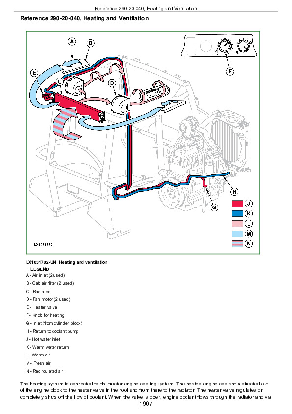
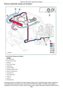
Reference 290-20-040, Heating and Ventilation
Section 299: Special Tools
Group 05: Special Tools (Dealer-Fabricated)
Reference 299-05-001, Special Tools (Dealer-Fabricated) — Summary
Reference 299-05-010, Holding Tool
Reference 299-05-011, Adjusting Tool
Reference 299-05-012, DFRW2—Needle Valve Test Hose Assembly
Reference 299-05-015, Special Tool for 29-BIT CAN BUS—DFLX12
Reference 299-05-016, DFLX14—Solenoid Test Harness
Group 10: Special Tools and Test Equipment
AR52361 – Socket
D01019AA – Manually operated hydraulic pump
FKM10002 or JT05470 – Pressure test kit
Battery Load Tester FKM10409
FKM10443 – Charging valve
FKM10444 – Leak detector
FKM10445 – Universal pressure test kit
FKM10447 – Refrigerant container (R134a; 920g; 750 ml)
FKM10470 – Pressure Measuring System (stage 1)
FKM10471 – Pressure measuring system (stage 2)
FKM10472 – Flow measurement system
FKM10472-4 – Temperature sensor
FKM10482 – Pressure Test Kit
Clamp-on Current Probe JT02153
JT03248 – Fitting
JT05791A – Multimeter
JT07115 – Pressure test kit
KJD10128 – Fitting
KJD10292 – Diagnostic Harness
KJD10194 – Pressure Test Kit
KJD10352 – Restriction fitting
KJD10495 – Hose connector
RE200689 – Performance monitor
RE37996 – Adjusting tool

John Deere Tractors Models 5620, 5720 and 5820 Diagnosis and Tests Technical Manual (TM4791)


INSTANT DOWNLOAD


Posted on

John Deere Tractors 5620, 5720, 5820 Diagnostic and Repair Technical Manual (TM4787)


INSTANT DOWNLOAD


Complete Repair Technical Manual for John Deere Tractors 5620, 5720, 5820 (2WD / MFWD), with all the service information to repair and service like professional mechanics.

John Deere 5620, 5720 and 5820 (2WD or MFWD) Tractors workshop repair technical manual includes:
* Numbered table of contents easy to use so that you can find the information you need fast.
* Detailed sub-steps expand on repair procedure information
* Numbered instructions guide you through every repair procedure step by step.
* Notes, cautions and warnings throughout each chapter pinpoint critical information.
* Bold figure number help you quickly match illustrations with instructions.
* Detailed illustrations, drawings and photos guide you through every procedure.
* Enlarged inset helps you identify and examine parts in detail.

TM4787 English – John Deere 5620, 5720, 5820 Tractors Technical Manual (Repair).pdf
tm4786 German – Traktoren 5620, 5720 und 5820
tm4788 French – Tracteurs 5620, 5720 et 5820Réparation -: (Version européenne)
tm4841 Italian – Trattori 5620, 5720 e 5820
tm8163 Czech – Traktory5620, 5720 a 5820Opravy
tm8220 Romanian – Reparareatractoarelor5620, 5720 şi 5820 -: (Versiunea europeană)
tm8221 Croatian – Traktori5620, 5720 i 5820Popravak -: (Europska verzija)

Total Pages: 1,601 pages
File Format: PDF (PC/Mac/Android/Kindle/iPhone/iPad; bookmarked, ToC, Searchable, Printable)
Language: English …

MAIN SECTIONS
  Foreword
   Version Date
   Safety
      Safety Measures
   General Information
      Specifications
      Tune-Up
      Predelivery Inspection
   Engine
      Engine Removal and Installation
   Fuel, Air Intake, Cooling and Exhaust Systems
      Speed Control Linkage
      Fuel System
      Air Intake System
      Cooling System
      Cold-Weather Starting Aid
      Exhaust System
   Electrical System
      Connectors
      Wiring Harnesses
      Charging Circuit
      Starting Motor Circuit
      Fuses, Relays and Switches
      Monitoring Systems
      Electrical Components
   PowrQuad and PowrQuad Plus Transmissions
      Removal and Installation of Components
      Transmission Shift Controls
      PowrQuad Module
      Reduction Gear
      Range Transmission
   Drive Systems
      Removal and Installation of Components
      U-Jointed Shafts and Torsion Damper
      Front-Wheel Drive Clutch
      Differential
      Hydraulic Pump Drive
      Final Drives
      Rear PTO
      Front PTO
   Steering and Brakes
      Hydrostatic Steering
      Brake Valve
      Rear Brakes
      Handbrake
      Hydraulic Trailer Brake
      Air Brakes
   Hydraulic System
      Controls
      Hydraulic Pump
      Valves
      Hitch
      Selective Control Valves and Couplers
   Miscellaneous
      Removal and Installation of Components
      Front and Rear Wheels
      Trailer Mounting and Swinging Drawbar
      Pick-Up Hitch
      Front Hitch
      Front Loader
   Operator’s Cab
      Removal and Installation of Components
      Controls and Instruments
      Air-Condtioning System
      Heating System
      Seats
      Operator’s Cab
      Parts for Electronic Hitch Control
   Special Tools (Dealer-Fabricated)
      Special Tools (Dealer-Fabricated)

tm4787 – 5620, 5720 and 5820 Tractors

Table of Contents

Foreword

Version Date

Section 05: Safety

Group 05: Safety Measures

Recognize Safety Information

”Important” Information

”Note” Information

Prevent Machine Runaway

Handle Fluids Safely—Avoid Fires

Prevent Battery Explosions

Prepare for Emergencies

Prevent Acid Burns

Avoid High-Pressure Fluids

Service Cooling System Safely

Remove Paint Before Welding or Heating

Avoid Heating Near Pressurized Fluid Lines

Work In Ventilated Area

Wear Protective Clothing

Practice Safe Maintenance

Park Machine Safely

Use Proper Lifting Equipment

Construct Dealer-Made Tools Safely

Support Machine Properly

Work in Clean Area

Illuminate Work Area Safely

Service Machines Safely

Use Proper Tools

Service Tires Safely

Service Front-Wheel Drive Tractor Safely

Safety Information – Air Brake System

Avoid Eye Contact With Radar

Keep ROPS Installed Properly

Replace Safety Signs

Dispose of Waste Properly

Live With Safety

Safety Measures on Electronic Control Units

Section 10: General Information

Group 05: Specifications

Specifications (Summary of References)

Engine Specifications

Cooling System

Fuel Injection Pump (Stanadyne)

Air Intake System

Electrical System

Hydrostatic Steering

Clutch

PowrQuad and PowrQuad Plus Transmissions

Reduction Gear

Rear PTO

Front PTO

Differential

Differential Lock

Final Drives

Front-Wheel Drive

Hydraulic Brakes

Handbrake

Parking Lock

Hydraulic System with Gear-Driven Pump

Rockshaft

Front Hitch

Ground Travel Speeds

Front and Rear Wheels

Dimensions and Weights

Capacities

Handling and Storing Diesel Fuel

Diesel Fuel

Lubricity of Diesel Fuel

Diesel Engine Break-In Oil

Diesel Engine Oil

Transmission and Hydraulic Oil

Front-Wheel Drive Axle Oil

Diesel Engine Coolant

Supplemental Coolant Additives

Grease

Oil Filters

Mixing of Lubricants

Lubricant Storage

Operating in Warm Temperature Climates

Alternative and Synthetic Lubricants

Unified Inch Bolt and Screw Torque Values

Metric Bolt and Screw Torque Values

Hydraulic system inch fitting torques

Hydraulic system metric fitting torques

Installing Oil Hoses

Product-Identification Number

Engine Serial Number

Transmission Serial Number

Front-Wheel Drive Axle Serial Number

Sub-assembly serial numbers

Group 10: Tune-Up

Tune-Up (Summary of References)

Specifications

Using High-Pressure Washers

Preliminary Engine Test

Preliminary Fuel System Test

Clean Dust Unloading Valve

Engine Air Cleaner

Cleaning the Primary Filter Element

Cleaning a Dusty Element

Secondary (Safety) Element

Installing the Primary Filter Element

Check Air Intake System Connections for Leaks

Check Crankcase Vent Hose for Clogging

Clean the Radiator Grille Screen

Keep the Radiator Screen Clean

Check the Caps on the Expansion Tank

Check Radiator for Leaks

Check Engine Thermostat

Check Operation of Fuel Transfer Pump

Checking the Fuel Filter

Bleed Air from Fuel System

Clean the Water Trap

Run the engine until it is warm, and check engine speeds

Check Setting of Fuel Injection Pump

Check Setting of Speed Control Linkage

Clean the Battery, Cables and Battery Box with a Clean Cloth

Checking the Neutral Start Circuit

Check Operation of Starting Motor

Checking the lighting circuit

Final Engine Check

Tractor Operation Check

Group 15: Predelivery Inspection

Predelivery Inspection

Section 20: Engine

Group 00: Engine Removal and Installation

Special or Essential Tools

Specifications

Remove Engine

Install Engine

Section 30: Fuel, Air Intake, Cooling and Exhaust Systems

Group 05: Speed Control Linkage

Speed Control (Summary of References)

Adjust Hand Throttle Lever and Accelerator Pedal

Recondition Hand Throttle Lever and Accelerator Pedal

Group 10: Fuel System

Fuel System (Summary of References)

General Information

Remove Fuel Tank

Install Fuel Tank

Replace Fuel Gauge Sending Unit

Replace Primary Fuel Filter

Replace Fuel Transfer Pump

Change Fuel Filter

Replacing the Check Valve in the Fuel Line

Replacing the Adapter in the Fuel Line

Bleed Air from Fuel System

Group 15: Air Intake System

Air Intake System (Summary of References)

General Information

Check Dust Unloading Valve

Remove and Install the Air Cleaner Element

Remove and Install Air Intake Hoses

Replace Sending Unit for Air Cleaner Restriction (B02)

Group 20: Cooling System

Cooling System (Summary of References)

General Information

Specifications

Remove and Install Radiator

Change Viscous Clutch of Fan

Remove and Install Thermostat and Temperature Sensor

Fill Cooling System with Coolant

Relieve Tension on Drive Belt

Replace Drive Belt

Replace Drive Belt Tensioner

Recondition Fan Console

Group 25: Cold-Weather Starting Aid

Fuel Preheater

Electrical Starting Aid

Coolant Heater

Group 30: Exhaust System

Exhaust System (Summary of References)

General Information

Exhaust System — Install Muffler (Tractor without Turbocharger)

Exhaust System — Install Muffler (Tractor with Turbocharger)

Exhaust System — Exhaust Pipe on Right of Cab Frame

Exhaust System — Exhaust Pipe to Top Right (Upright)

Exhaust System — Exhaust Pipe to Bottom Right

Section 40: Electrical System

Group 05: Connectors

Connectors – Reconditioning (Summary of References)

Special Tools

General

Using high-pressure washers

Disconnecting electrical circuits

Stripping Wire Ends

Installing a Terminal

METRI PACK Connector with Terminal Lock at the Rear

METRI PACK Connectors

Connectors for Electronic Control Units

Connectors

CRIMP SNAP IN connectors

DEUTSCH Connectors

Individual Terminals

Fuse and Relay Boxes

Group 10: Wiring Harnesses

Wiring Harnesses for Tractors with PowrQuad Transmission – Reconditioning (Summary of References)

Wiring Harnesses for Tractors with PowrQuad Transmission from Serial No. 436758 – Reconditioning (Summary of References)

Wiring Harnesses for Tractors with PowrQuad Plus Transmission – Reconditioning (Summary of References)

Wiring Harnesses for Tractors with PowrQuad Plus Transmission from Serial No. 434662 – Reconditioning (Summary of References)

Ground Point Locations

Remove and Install Harness W01 — Power Supply and Starting Aid

Remove and Install Harness W01 — Power Supply and Starting Aid from Serial No. 436764

Remove and Install Harness W02 — Engine

Remove and Installing Harness W04 — Headlights

Remove and Install Harness W07 — Front PTO

Remove and Install Harness W08 — Cab, for Tractors with PowrQuad Transmission

Remove and Install Harness W08 — Cab, for Tractors with PowrQuad transmission from Serial No. 436758

Remove and Install Harness W08 — Cab, for Tractors with PowrQuad Plus Transmission

Remove and Install Harness W08 — Cab, for Tractors with PowrQuad Plus transmission from Serial No. 434662

Remove and Install Harness W13 — Clutch Sender

Remove and Install Harness W14 — 3-Terminal Power Outlet Socket

Remove and Install Harness W18 — Windshield Wiper Switch (without Intermittent Wipe)

Remove and Install Harness W18 — Windshield Wiper Switch (with Intermittent Wipe)

Remove and Install Harness W19 — Cab Roof and Fan

Remove and Install Harness W20 — Turn Signal and Clearance Lights

Remove and Install Harness W21 — Adapter for Worklights on Cab Roof

Remove and Install Harness W23 — Windshield Wiper (with Hinged Windshield)

Remove and Install Harness W28 — Front End of Transmission, for Tractors with PowrQuad Transmission

Remove and Install Harness W28 — Front End of Transmission, for tractors with PowrQuad transmission from Serial No. 431378

Remove and Install Harness W28 — Front End of Transmission, for Tractors with PowrQuad Plus Transmission

Remove and Install Harness W28 — Front End of Transmission, for Tractors with PowrQuad Plus transmission from Serial No. 424816

Remove and Install Harness W30 — Rear End of Transmission

Remove and Install Harness W42 — Battery Cut-Off Switch, Version 1

Remove and Install Harness W42 — Battery Cut-Off Switch, Version 2

Remove and Install Harness W46 — Front PTO, Adapter

Group 15: Charging Circuit

Charging Circuit – Reconditioning (Summary of References)

Special Tools

Specifications

Repairing the Alternator

Disconnecting Electrical Circuits

Relieve Drive Belt Tension

Remove/Install the Alternator

Remove and Install Pulley

Group 20: Starting Motor Circuit

Starting Motor Circuit – Reconditioning (Summary of References)

Specifications

Repairing the Starter Motor

Disconnecting Electrical Circuits

Remove and Install Starting Motor

Group 25: Fuses, Relays and Switches

Fuses, Relays and Switches – Reconditioning (Summary of References)

General Information

Specifications

Disconnecting electrical circuits

Remove Trim Panels from Cowl on Tractors with PowrQuad Transmission

Remove Trim Panels from Cowl on Tractors with PowrQuad Plus Transmission

Fuse and Relay Boxes

Replace Main Fuses up to Serial No. 436763

Replace Main Fuses from Serial No. 436764

Replace the Fuses for the Electrical Starting Aid up to Serial No. 436763

Replace the Fuses for the Electrical Starting Aid from Serial No. 436764

Replace the Fuse for the Indicator Light in the Switch that Operates the Battery Cut-Off Switch (Version 2)

Additional Fuse for Front Loader

Replace Starting Motor Relay up to Serial No. 436763

Replace Starting Motor Relay from Serial No. 436764

Replace the Relay for the Electrical Starting Aid up to Serial No. 436763

Replace the Relay for the Electrical Starting Aid from Serial No. 436764

Replace Battery Cut-Off Relay

Replace Battery Cut-Off Switch Relay

Replace Main Switch

Replace Brake Switches

Replace Light Switch

Replace Full/Dipped-Beam Switch

Replace Hazard Warning Light Switch

Replace Turn Signal Switch

Replace Horn Switch

Replace Switches on Multi-Function Unit

Replace Windshield Wiper and Washer Switch

Replace Rear Window Wiper and Washer Switch

Replace Worklight Switch

Replace Switch for Lights on Cab Frame

Replace Beacon Light Switch

Replace Dome Light Door Switch

Replace Handbrake Switch

Replace Front-Wheel Drive Switch

Replace Headland Management (HMS) Switch

Replace Record/Save Switch

Replace Program Switch

Replace Rear PTO Preselector Switch

Replace Gear Selector Switches

Replace Fan Switch

Replace Switch of the Air-Conditioning System Compressor

Replace Differential Lock Switch

Replace PTO Switches

Replace External Control Switch for the Rear PTO

Replace Rockshaft Remote Control Switch

Replace Switch that Operates the Battery Cut-Off Switch

Rockshaft Control

Group 30: Monitoring Systems

Monitoring Systems – Reconditioning (Summary of References)

General Information

Repairing 4.5- & 6.8-liter POWERTECH Diesel Engines (Basic Engine)

Repairing 4.5- & 6.8-liter POWERTECH Diesel Engines (Mechanical Fuel Injection Systems)

Specifications

Disconnecting electrical circuits

Replace Engine Speed Sending Unit (B01)

Replace Engine Oil Pressure Sending Unit (B04)

Replace Sending Unit for the Coolant Temperature Gauge (B08)

Replace Acoustic Alarm

Group 40: Electrical Components

Electrical Components – Reconditioning (Summary of References)

General Information

Special or Essential Tools

Specifications

Disconnecting electrical circuits

Replace 7-Terminal Power Outlet Socket

Replace 3-Terminal Power Outlet Socket

Replace Multiple Power-Outlet Socket Strip

Replace Service Socket

Remove Wiper Motor

Adjusting the Headlights

Adjust Lights on the Cab Frame

Safety Instructions for Replacing a Halogen Bulb

Section 55: PowrQuad and PowrQuad Plus Transmissions

Group 00: Removal and Installation of Components

Removal and Installation of Components—Transmission (Summary of References)

Special Tools

Dealer-Fabricated Special Tools

Specifications

PowrQuad Plus Transmission, Removal and Installation

Remove PowrQuad Transmission

Install PowrQuad Transmission

Remove Reduction Gear

Install Reduction Gear

Remove Range Transmission

Install Range Transmission

Group 05: Transmission Shift Controls

PowrQuad Transmission Shift Units — Reconditioning (Summary of References)

Specifications

Recondition Gear Shift Linkage

Recondition Range Shift Linkage (Shift Elements)

Recondition Range Shift Linkage (Lever and Gate)

Recondition the Actuator of the Reduction Gear

Adjust the Shifter of the Reduction Gear

Recondition Reverser Control (Mechanical)

Adjusting the Reverse Drive Lever (Mechanical)

Adjust Reverse Drive Linkage

Check and Adjust Shift Units

Adjust the Clutch Pedal (PowrQuad Transmission)

Recondition Clutch Actuation (PowrQuad Plus Transmission)

Group 10: PowrQuad Module

Special or Essential Tools

Specifications

PowrQuad and PowrQuad Plus Transmissions—Summary of References

Transmission Components

Replace the Neutral Start Switch (with Mech. Actuated PowrQuad Module)

Replace Temperature Sensor and Pressure Switches

Removing and Installing the Oil Filter Housing

Removing and Installing the Front Valve Housing

Removing and Installing the Valves in the Front Valve Housing

Remove and Install Valves in the Front Valve Housing (with Mech. Actuated PowrQuad Module)

Removing and Installing the Front Transmission Cover

Removing and Installing the Valves in the Front Transmission Cover

Removing and Installing the Valves in the Front Transmission Cover (with Mech. Actuated PowrQuad Module)

Replacing the Clutch Pedal Valve (with Mech. Actuated PowrQuad Module)

Remove and Install Shift Valve Housing

Remove and Install Valves in the Shift Valve Housing

Removing and Installing the Shift Valve Housing (with Mech. Actuated PowrQuad Module)

Removing and Installing the Valves in the Shift Valve Housing (with Mech. Actuated PowrQuad Module)

Removing the Transmission Oil Pump

Reconditioning the Transmission Oil Pump

Installing the Transmission Oil Pump

Removing the Gear-Shift Planetary Drive

Repairing the Gear-Shift Planetary Drive

Install Gear-Shift Planetary Drive

Removing the B1 Brake Housing

Reconditioning the B1 Brake

Installing the B1 Brake Housing

Removing the B2-B3 Brake Housing

Reconditioning the B2 Brake

Reconditioning the B3 Brake

Installing the B2-B3 Brake Housing

Removing the C4 Clutch

Recondition the C4 Clutch

Installing the C4 Clutch

Removing the Reverse Brake

Reconditioning the Reverse Brake

Installing the Reverse Brake

Removing the Forward Clutch with Planetary Drive (Forward/Reverse)

Recondition Forward Clutch with Planetary Drive (Forward/Reverse)

Installing the Forward Clutch with Planetary Drive (Forward/Reverse)

Replacing the Output Shaft

Group 15: Reduction Gear

Reduction Gear — Summary of References

Exploded View of Reduction Gear

Recondition Reduction Gear

Pre-Assembly of Reduction Gear

Measure the Gaps at the Reduction Gear Connecting Ring

Remove and Install Bearing of Reduction Gear Countershaft

Group 25: Range Transmission

Specifications

Range Transmission—Reconditioning (Summary of References)

Remove Range Transmission

Recondition Range Transmission

Install Range Transmission

Recondition Shift Cover

Replace Speed Sending Unit

Section 56: Drive Systems

Group 00: Removal and Installation of Components

Removal and Installation of Components (Summary of References)

Special or Essential Tools

Dealer-Fabricated Special Tools

Specifications

Remove Front-Wheel Drive Clutch

Install Front-Wheel Drive Clutch

Remove Differential Housing

Install Differential Housing

Remove Final Drives

Install Final Drives

Remove Rear PTO

Install Rear PTO

Remove Front PTO

Install Front PTO

Group 05: U-Jointed Shafts and Torsion Damper

Summary of References (U-Jointed Shafts and Torsion Damper)

Special Tools

Use of Special Tool KJD10426

Specifications

Remove U.j. Shaft (Front-Wheel Drive)

Install U.j. Shaft (Front-Wheel Drive)

Disassemble U.j. Shaft (Front-Wheel Drive)

Assemble U.j. Shaft (Front-Wheel Drive)

Remove U.j. Shaft (Engine)

Install U.j. Shaft (Engine)

Remove Torsion Damper

Install Torsion Damper

Change Torsion Damper Bearings

Group 10: Front-Wheel Drive Clutch

Front-Wheel Drive Clutch — Reconditioning (Summary of References)

Special Tools

Other material

Specifications

Change Wheel Speed Sending Unit

Disassemble Front-Wheel Drive Clutch

Front-Wheel Drive Clutch — Exploded View

Assemble Front-Wheel Drive Clutch

Group 15: Differential

Differential — Reconditioning (Summary of References)

Specifications

Remove Differential Lock

Remove Differential

Disassemble Differential

Differential and Differential Lock — Exploded View

Assemble Differential

Install Differential

Disassemble Differential Lock

Assemble Differential Lock

Install Differential Lock

Group 20: Hydraulic Pump Drive

Hydraulic Pump Drive — Reconditioning (Summary of References)

Specifications

Remove Hydraulic Pump Drive

Hydraulic Pump Drive—Exploded View

Install Hydraulic Pump Drive

Group 25: Final Drives

Final Drives — Reconditioning (Summary of References)

Special or Essential Tools

Specifications

Disassemble Final Drives

Final Drives—Sectional View

Final Drives—Exploded View

Final Drives—Reconditioning the Planetary Carrier

Assemble Final Drives

Final Drives—Adjust Rolling Drag Torque

Group 30: Rear PTO

Rear PTO — Reconditioning (Summary of References)

Other Material

Specifications

Replace Output Shaft Seal Ring

Remove PTO Clutch

Exploded View of PTO Clutch

Recondition PTO Clutch

Install PTO Clutch

Disassemble PTO Drive Train

Recondition Output Shaft, 540/540E/1000 rpm

Recondition Output Shaft (540/540E rpm)—Exploded View

Recondition Countershaft (540/540E rpm and 540/540E/1000 rpm)

Assemble PTO Shifter (540/540E rpm and 540/540E/1000 rpm)

Assemble PTO Drive Train

Install Support and Adjust Taper Roller Bearings

Remove PTO Modulating Valve

Recondition PTO Modulating Valve

Install PTO Modulating Valve

Recondition Solenoid Valve

Replace PTO Speed Sending Unit

Change and Adjust Bowden Cable

Group 35: Front PTO

Front PTO — Reconditioning (Summary of References)

Specifications

General Repair Procedures

Clean Oil Screen

Replace Solenoid Valve

Remove Oil Pump

Exploded View of Oil Pump

Install the Oil Pump

Front PTO — Sectional View

Disassemble Front PTO

Disassemble Front PTO Clutch

Assemble Front PTO Clutch

Assemble Front PTO

Front PTO — Remove Constant-Velocity Joint from Drive Shaft

Front PTO — Install Constant-Velocity Joint on Drive Shaft

Remove Front PTO Oil Cooler

Install Front PTO Oil Cooler

Section 60: Steering and Brakes

Group 05: Hydrostatic Steering

Hydrostatic Steering (Summary of References)

Special or Essential Tools

Specifications

Preliminary Work

Disconnect/Connect Steering or Brake Hoses

Remove and Install Steering Valve

Exploded View of Steering Valve

Recondition Steering Wheel and Steering Column

Group 15: Brake Valve

Summary of References (Brake Valve)

Specifications

Remove and Install Brake Valve

Group 20: Rear Brakes

Summary of References (Rear Brakes)

Remove Rear Brakes

Install Rear Brake

Final Assembly

Bleeding the Brakes

Group 25: Handbrake

Handbrake (Summary of References)

Special or Essential Tools

Specifications

Remove Handbrake

Handbrake — Exploded View

Disassemble Handbrake

Assemble Handbrake

Install Handbrake

Handbrake — Components

Check and Adjust Handbrake

Group 30: Hydraulic Trailer Brake

Hydraulic Trailer Brake (Summary of References)

Special Tools

Specifications

Repair Instructions

Change Trailer Brake Valve

Clean the Trailer Brake Valve

Cleaning the Screen

Replace the Check Valve

Bleed Air from the Trailer Brake Valve

Check Hydraulic Trailer Brake Valve

Adjust Hydraulic Trailer Brake Valve

Group 35: Air Brakes

Summary of References (Air Brakes)

Special Tools

Specifications

Screw Union Installation

Change Compressor

Gaskets for the Compressor

Change Compressed Air Tank

Change Pressure Control Valve

Change Trailer Control Valve

Change Coupling Ends

Test Sequence

Check Air Brake System (Visual Checks)

Check System for Leaks

Check the “Supply” Coupling End

Check Dual-Line Brake

Check Single-Line Brake

Adjusting the Handbrake (with Air Brake System)

Section 70: Hydraulic System

Group 05: Controls

Hydraulic System — Controls (Summary of References)

Specifications

Selective Control Valves — Remove and Install the Actuating Elements

Selective Control Valves — Adjusting the Bowden Cable

Remove and Install the Multi-Function Lever

Adjust Multi-Function Lever

Group 10: Hydraulic Pump

Specifications

Remove Hydraulic Pump

Recondition Hydraulic Pump

Install Hydraulic Pump

Group 15: Valves

Reconditioning the Valves (PC Hydraulic System) — Summary of References

Special Tools

Specifications

Hydraulic System — General Instructions on Safety and Repair

Direct Control of Rockshaft

Remove and Install Rockshaft Valve

Recondition the Hitch Valve

Rockshaft Valve — Depth to Which Raising and Lowering Valves are Screwed In

Rockshaft Valve — Removing and Installing the Stepper Motor

Rockshaft Valve — Centering the Stepper Motor

Remove and Install Priority Valve

Recondition the Priority Valve

Remove and Install By-Pass Valve

Group 20: Hitch

Hitch — (Summary of References)

Special or Essential Tools

Self-Manufactured Special Tools

Other Material

Specifications

Rockshaft — Removing and Installing the Position Sensor and Toothed Segment

Remove and Install Rockshaft Housing

Removal and installation

Remove Rockshaft Cylinders

Install Rockshaft Cylinders

Remove and Install Draft Sensor and Draft Link Bearing Pins

Automatic Stabilizer Rod

Stabilizing Rod Bracket

Group 25: Selective Control Valves and Couplers

Reconditioning the Selective Control Valves and Couplers — Summary of References

Special Tools

Other Material

Specifications

Reconditioning the Selective Control Valves and Couplers — General Instructions on Safety and Reconditioning

SCV Identification

Arrangement of the Shuttle Valves

Remove and Install Selective Control Valves

Series 105 and 205 Selective Control Valves — Exploded View

Series 105 and 205 Selective Control Valves — Disassembly

Series 105 and 205 Selective Control Valves — Assembly

Series 305 Selective Control Valves — Exploded View

Series 305 Selective Control Valves — Disassembly

Series 305 Selective Control Valves — Assembly

Selective Control Valves — Reconditioning the Couplers

Selective Control Valves – Hydraulically Actuated Shut-Off Valves

Install a Front Loader

Section 80: Miscellaneous

Group 00: Removal and Installation of Components

Special or Essential Tools

Dealer-Fabricated Special Tools

Specifications

Remove Main Frame

Install Main Frame

Remove Front-Wheel Drive Axle

Install Front-Wheel Drive Axle

Remove Front Axle Support

Install Front Axle Support

Group 15: Front and Rear Wheels

Special or Essential Tools

Specifications

Front Wheels, Rear Wheels and Fenders—Reconditioning (Summary of References)

Remove Front and Rear Wheels

Recondition Front and Rear Wheels

Install Front and Rear Wheels

Pivoting (Front) Fender

Group 20: Trailer Mounting and Swinging Drawbar

Trailer Mounting and Swinging Drawbar – Reconditioning (Summary of References)

Specifications

Checking the Manually-Operated Hitch for Wear

Checking the Manually-Operated Hitch for Wear (Italy and Spain Only)

Checking the Remote Controlled Hitch for Wear

Checking the Tow-Hook for Wear

Check the Swinging Drawbar for Wear

Install the Center Link Support

Guide Rails for Height-Adjustable Trailer Hitch

Repair of Automatic Trailer Hitch

Remote Control for Automatic Trailer Hitch

Swinging Drawbar

Proper Use of Drawbar

Swinging Drawbar with Pick-Up Hitch

Group 30: Pick-Up Hitch

Pick-Up Hitch — Summary of References

Specifications

Other Material

Check Tow-Hook on Pick-Up Hitch for Wear

Install Pick-Up Hitch

Adjust the Lift Links

Check and Adjust the Retainer Spring

Recondition the Latch Housing

Repairing the Hydraulic Cylinder

Adjust the Guide Stop

Adjust the Locking Pin

Operational Check of Pick-Up Hitch

Group 40: Front Hitch

Front Hitch – Reconditioning (Summary of References)

Remove Front Hitch

Install Front Hitch

Remove and Install Bracket for Mowing Unit Suspension

Remove Lines and Hoses from Front Hitch without Multi-Valve

Install Lines and Hoses on Front Hitch without Multi-Valve

Remove Lines and Hoses from Front Hitch with Multi-Valve

Install Lines and Hoses on Front Hitch with Multi-Valve

Remove and Install Front Hitch Multi-Valve

Remove and Install Front Hitch Accumulator

Service the Front Hitch Accumulator

Group 50: Front Loader

Remove and Install the Mountings

Section 90: Operator’s Cab

Group 00: Removal and Installation of Components

Operator’s Cab, Removal and Installation of Components – Summary of References

Special Or Essential Tools

Specifications

Operator’s Cab, Tilting or Removing and Installing

Tilt Operator’s Cab Upward

Tilt Operator’s Cab Downward

Disconnect/Connect Steering or Brake Hoses

Remove Operator’s Cab

Install Operator’s Cab

Check and Adjust Shift Units

Group 05: Controls and Instruments

Controls and Instruments (Summary of References)

Replacing Bulbs on the Instrument Unit

Replace Control Unit (EPC)

Replace Control Unit (BCU)

Replace Terminating Bus Resistors

Replace the Performance Monitor (PRF)

Replace the Basic Informator (BIF)

Group 10: Air-Condtioning System

Air-Conditioning System (Summary of References)

Special Tools

Specifications

Torques for Tightening Refrigerant Hoses

Safety At Work

Handling Refrigerant

In an Emergency

Safety Equipment

Storage of Refrigerant Containers

R134A Refrigerant

Important Note

Discharge the System

Evacuate the System

Fill with Refrigerant Oil

Instructions for Starting Up the DENSO Air-Conditioning Compressor

Charge the System

Leakage Test

Remove and Install Compressor

Checking Level in the Compressor

Disassemble Compressor Clutch

Checking Clutch Hub Clearance

Checking the Compressor Manifold

Remove and Install Condenser

Remove and Install Receiver-Drier

Remove and Install the Evaporator and Expansion Valve

Arrangement of Condensation Water Drain Hoses

Remove and Install Thermostat Switch

Adjust Thermostat Switch Bowden Cable

Remove and Install the High/Low Pressure Switch

Group 15: Heating System

Heating System (Summary of References)

Remove and Install Radiator

Remove and Install Fan Motors

Remove and Install Fan Motor Resistors

Remove and Install Heater Valve

Adjust Heater Valve Bowden Cable

Remove and Install Control Console for Ventilation System

Change Air Hoses in Ventilation System

Group 20: Seats

Specifications

Comfort Seat MSG83

Air Comfort Seat MSG95A-00, Lower Section

Passenger Seat, Exploded View

Group 25: Operator’s Cab

Operator’s Cab (Summary of References)

Cab Mounting Torques

Remove and Install Windshield

Remove and Install Rear Window

Remove and Install Sun Roof

Installing Door Lock

Remove and Install Cab Door

Remove Trim Panels from Switch Console

Remove Inner Roof Trim

Install Inner Roof Trim

Group 30: Parts for Electronic Hitch Control

Electronic Hitch Control (Summary of References)

Disconnecting Electrical Circuit

Service Information

Replace Control Unit (BCU)

Replace Hitch Control Operation Unit

Section 99: Special Tools (Dealer-Fabricated)

Group 05: Special Tools (Dealer-Fabricated)

DFLX1 – Adapter Strut

DFLX2 – Suspension Device for Perma Clutch II and Power Reverser Module

DFLX6 – Bushing

DFLX7 – Turning Device

DFLX10 – Holding Tool

DFLX32 – Holding Device

DFLX38 – Turning Device

DFRW2 – Needle Valve Test Hose Assembly

Group 10: Special Tools (available as spare parts)

AR52361 – Socket

D01019AA – Manually-Operated Hydraulic Pump

D01042AA – Load-Positioning Sling

FKM10002 or JT05470 – Pressure Test Kit

FKM10409 – Battery Tester

FKM10427 – Crimping Pliers

FKM10443 – Charging Valve

FKM10444 – Leak Detector

FKM10445 – Universal Pressure Test Kit

FKM10447 – Refrigerant Container (R134a; 920g; 750 ml)

FKM10470 – Pressure Measuring System (Stage 1)

FKM10471 – Pressure Measuring System (Stage 2)

FKM10472 – Flow Measurement System

FKM10472-4 – Temperature Sensor

FKM10482 – Pressure Test Kit

JDG19 – Special Mounting Brackets

JDG23 – Lifting Sling

JT02043 – Support Stand

JT02044 – Support Stand

JT02153 – Clamp-On Current Probe

JT03248 – Fitting

JT05723 – Medium-Duty Rear Tractor Splitting Stand

JT05791A – Multimeter

JT07115 – Pressure Test Kit

JT07211 – Support Stand

KJD10128 – Fitting

KJD10178C – Cab Tilting Device

KJD10194 – Pressure Test Kit

KJD10283 – Supplementary Kit

KJD10292 – Diagnostic Harness

KJD10352 – Restriction Fitting

KJD10495 – Hose Connector

KJD10501 – Disconnecting Tools (Kit)

RE200689 – Performance Monitor

RE37996 – Adjusting Tool

John Deere Tractors 5620, 5720, 5820 Diagnostic and Repair Technical Manual (TM4787)


INSTANT DOWNLOAD