INSTANT DOWNLOAD
Complete Repair Service Technical Manual for John Deere Tractors 7185J, 7195J, 7205J, 7210J & 7225J (Worldwide), with workshop information to maintain, repair, and rebuild like professional mechanics.
John Deere Tractors 7185J, 7195J, 7205J, 7210J, 7225J workshop technical manual (repair) includes:
* Numbered table of contents easy to use so that you can find the information you need fast.
* Detailed sub-steps expand on repair procedure information
* Numbered instructions guide you through every repair procedure step by step.
* Troubleshooting and electrical service procedures are combined with detailed wiring diagrams for ease of use.
* Notes, cautions and warnings throughout each chapter pinpoint critical information.
* Bold figure number help you quickly match illustrations with instructions.
* Detailed illustrations, drawings and photos guide you through every procedure.
* Enlarged inset helps you identify and examine parts in detail.
TM802019 English – John Deere 7185J, 7195J, 7205J, 7210J, and 7225J Tractors Diagnostics Technical Manual.pdf
tm802028 French – Tracteurs 7185J, 7195J, 7205J, 7210J et 7225J—Manuel technique de diagnostic
tm802054 Portuguese – Tratores 7185J, 7195J, 7205J, 7210J e 7225J — Manual Técnico de Diagnóstico
TM2240 English – Original Diagnosis and Tests Manual
tm2820 English – Starfire Real Time Kinematic (RTK) Base Station Diagnosis and Tests Technical Manual.pdf
PRODUCT DETAILS:
Total Pages: 4,223 pages
File Format: PDF (bookmarked, ToC, Searchable, Printable, high quality)
Language: English French Portuguese
MAIN SECTIONS
Foreword
General
Safety
General Specifications
General References
Diagnostic Trouble Codes
ACU Code Diagnostics
CAB Code Diagnostics
CCU Code Diagnostics
ECU Code Diagnostics
HCU Code Diagnostics
ICU Code Diagnostics
PTQ Code Diagnostics
SSU Code Diagnostics
TEC Code Diagnostics
Observable Symptoms
Engines
Fuel and Air
Electrical
Control Units
PowrQuad-Plus Transmissions
Drive Systems
Steering and Brakes
Hydraulics
Operator Station
System Diagnosis
Lighting
Starting, Charging and Start Aid
CAN System Diagnosis
PowrQuad-Plus Transmission
Differential Lock
MFWD
Rear PTO
Rear Brake
Steering
Air Trailer Brake System Diagnosis
AutoTrac System Diagnosis (TSN -70000)
AutoTrac System Diagnosis (TSN 70001-)
Hydraulic System Diagnosis
Rear Hitch System Diagnosis
Manual Seat
Manual Air Conditioning
Wiper System
Engines
General Information
Test And References
Engine System Theory of Operation
Schematics and Diagrams
Fuel and Air
Fuel and Air Theory of Operation
Electrical
Load Center Fuses and Relays
Operational Checks
Tests and Adjustments
Theory Of Operation
Functional Schematics
Connector Information – 7185J and 7205J
Connector Information – 7195J, 7210J and 7225J
Control Units
General References
Tests and Adjustments
ACU
CAB
CCU
ECU
HCU
ICU
PTQ
SSU
TEC
PowrQuad-Plus Transmission
General Information
Operational Checks
Tests and Adjustments
PowrQuad-Plus Theory of Operation
Schematics and Diagrams
Drive Systems
Preliminary And Operational Checks
Test References
Theory Of Operation
Schematics and Diagrams
Steering and Brakes
Preliminary Checks
Preliminary And Operational Checks
Test And Adjustments
Theory Of Operation
Schematics and Diagrams
Hydraulics
General References
Operational and Preliminary Checks
Tests and Adjustments
Theory Of Operation
Schematics and Diagrams
Operator Station
Preliminary Checks
Operational Checks
Tests and Adjustments
Theory Of Operation
Schematics and Diagrams
Service Tools
Dealer Fabricated Tools
TABLE OF CONTENTS
Section 210: General….56
Group 05: Safety….56
Recognize Safety Information….59
Handle Fluids Safely—Avoid Fires….60
Prevent Battery Explosions….61
Prepare for Emergencies….62
Prevent Acid Burns….63
Handle Chemical Products Safely….65
Avoid High-Pressure Fluids….66
Park Machine Safely….67
Support Machine Properly….68
Wear Protective Clothing….69
Work in Clean Area….70
Service Machines Safely….71
Work In Ventilated Area….72
Illuminate Work Area Safely….73
Replace Safety Signs….74
Use Proper Lifting Equipment….75
Remove Paint Before Welding or Heating….76
Avoid Heating Near Pressurized Fluid Lines….77
Keep ROPS Installed Properly….78
Avoid Harmful Asbestos Dust….79
Practice Safe Maintenance….80
Use Proper Tools….82
Decommissioning — Proper Recycling and Disposal of Fluids and Components….83
Prevent Machine Runaway….84
Handle Starting Fluid Safely….85
Service Cooling System Safely….86
Stay Clear of Rotating Drivelines….87
Protect Against High Pressure Spray….89
Construct Dealer-Made Tools Safely….90
Clean Vehicle of Hazardous Pesticides….91
Live With Safety….92
Group 10: General Specifications….57
Reference 210-10-001, General Specifications….94
Reference 210-10-002, General Reference List….95
Group 15: General References….57
Reference 210-15-002, Bolt and Cap Screw Torque Values….98
Reference 210-15-003, Glossary of Terms….100
Standard Hydraulic Symbols….108
Reference 210-15-005, Wiring Diagram and Schematic Information….112
Reference 210-15-006, Electrical Schematic Symbols….113
Reference 210-15-007, Reading Wiring Schematics and Diagrams….116
Reference 210-15-008, Visually Inspect Electrical System….120
Reference 210-15-009, Seven Step Electrical Procedure With probe light or multimeter….57
Reference 210-15-010, Using a Probe Light….124
Reference 210-15-011, Circuit Types….126
Reference 210-15-012, Circuit Malfunctions….128
Reference 210-15-013, Troubleshooting Circuit Malfunctions….131
Reference 210-15-014, Understanding Electrical vs. Electronic Circuits….136
Reference 210-15-015, Intermittent Electronic Problems….139
Reference 210-15-016, Relay Circuit Types….142
Reference 210-15-017, Using a Digital Multimeter….155
Reference 210-15-101, Troubleshooting Unresolved Problems….157
Section 211: Diagnostic Trouble Codes….158
Group ACU: ACU Code Diagnostics….158
ACU 000158.04 – ACU Switched Supply Voltage Low….158
ACU 000177.17 – Engine Speed Limited Due to Cold Oil….158
ACU 000237.02 – VIN Security Data Conflict….158
ACU 000237.14 – VIN Security Not Enabled….158
ACU 000237.31 – VIN Security Messages Missing….158
ACU 000581.07 – Transmission Not Responding to Command….158
ACU 000587.31 – Engine Type Unknown….158
ACU 000628.02 – ACU EOL Data Fault….158
ACU 000628.12 – ACU Programming….158
ACU 000629.11 – ACU Control Unit Fault….158
ACU 000629.12 – ACU Control Unit Fault….158
ACU 000630.02 – ACU Calibration Fault/Data Invalid….158
ACU 000630.13 – ACU Calibration Fault/Not Calibrated….158
ACU 000974.02 – Hand Throttle Sensor Circuit Voltage Conflict….158
ACU 000974.03 – Hand Throttle Sensor Circuit Voltage High….158
ACU 000974.04 – Hand Throttle Sensor Circuit Voltage Low….158
ACU 001079.02 – ACU Sensor Supply 1 Voltage Fault….158
ACU 001079.03 – ACU Sensor Supply 1 Voltage High….158
ACU 001079.04 – ACU Sensor Supply 1 Voltage Low….158
ACU 001080.02 – ACU Sensor Supply 2 Voltage Fault….158
ACU 001080.03 – ACU Sensor Supply 2 Voltage High….158
ACU 001080.04 – ACU Sensor Supply 2 Voltage Low….158
ACU 002000.09 – ECU Message Missing….158
ACU 002003.09 – PTI or PTQ Message Missing….158
ACU 002049.09 – CAB Message Missing….158
ACU 523664.02 – Speed Band 1 and 2 Switches Conflict….158
ACU 523923.02 – SCV I Control Lever Switch/Sensor Conflict….158
ACU 523923.03 – SCV I Control Lever Sensor Circuit Voltage High….158
ACU 523923.04 – SCV I Control Lever Sensor Circuit Voltage Low….158
ACU 523953.02 – Speed Control Lever Sensor Circuit Conflict….158
ACU 523953.03 – Speed Control Lever Sensor Voltage High….158
ACU 523953.04 – Speed Control Lever Sensor Voltage Low….159
ACU 523954.07 – Speed Band 1 Adjustment Fault….159
ACU 523954.11 – Set Speed Adjuster Conflict….159
ACU 523955.31 – Engine Overload In Manual Mode….159
ACU 523958.31 – Reversing Ratio Fault….159
ACU 523960.17 – Operator Not Present At Low Speeds….159
ACU 523960.31 – Operator Not Seated During Reverser Command….159
ACU 523961.02 – Park Engaged While in Gear….159
ACU 523961.07 – Park Lock Engagement Fault….159
ACU 523962.31 – MFWD Speed Incorrect….159
ACU 523963.02 – Speed Band 1 Switch/Voltage Conflict….159
ACU 523966.31 – Transmission Come Home Mode….159
ACU 523967.02 – Speed Band 2 Switch/Voltage Conflict….159
ACU 523968.02 – IMS Switch Circuits Conflict….159
ACU 523968.03 – IMS Switch Circuits Voltage High….159
ACU 523968.04 – IMS Switch Circuits Voltage Low….159
ACU 523969.11 – Upshift/Downshift Switch Conflict….159
ACU 523971.02 – Rear Hitch Control Lever Switch/Sensor Circuit Conflict….159
ACU 523971.03 – Rear Hitch Control Lever Sensor Circuit Voltage High….159
ACU 523971.04 – Rear Hitch Control Lever Sensor Circuit Voltage Low….159
ACU 524020.31 – Transmission in Gear at Power Up….159
ACU 524103.02 – SCV IV Control Lever Switch/Sensor Circuit Conflict….159
ACU 524103.03 – SCV IV Control Lever Sensor Circuit Voltage High….159
ACU 524103.04 – SCV IV Control Lever Sensor Circuit Voltage Low….159
ACU 524104.02 – SCV III Control Lever Switch/Sensor Circuit Conflict….159
ACU 524104.03 – SCV III Control Lever Sensor Circuit Voltage High….159
ACU 524104.04 – SCV III Control Lever Sensor Circuit Voltage Low….159
ACU 524105.02 – SCV II Control Lever Switch/Sensor Circuit Conflict….159
ACU 524105.03 – SCV II Control Lever Sensor Circuit Voltage High….159
ACU 524105.04 – SCV II Control Lever Sensor Circuit Voltage Low….159
ACU 524212.02 – Rear Hitch Control Lever Switch/Sensor Circuit Conflict….159
ACU 524212.03 – Rear Hitch Control Lever Sensor Circuit Voltage High….159
ACU 524212.04 – Rear Hitch Control Lever Sensor Circuit Voltage Low….159
ACU 524224.02 – Rear PTO Switch Circuit Conflict….160
ACU 524224.14 – Rear PTO Disabled….160
ACU 524254.31 – Transmission Enable Circuit Fault….160
Group CAB: CAB Code Diagnostics….160
CAB 000091.02 – Foot Throttle Sensor Circuit Voltage Conflict….160
CAB 000091.03 – Foot Throttle Sensor Circuit Voltage High….160
CAB 000091.04 – Foot Throttle Sensor Circuit Voltage Low….160
CAB 000158.00 – CAB Switched Supply Voltage High….160
CAB 000158.01 – CAB Switched Supply Voltage Low w/Engine Running > 1500 rpm….160
CAB 000158.17 – CAB Switched Supply Voltage Low w/Engine OFF….160
CAB 000158.18 – CAB Switched Supply Voltage Low w/Engine Running <1500 rpm….160
CAB 000237.02 – VIN Security Data Conflict….160
CAB 000237.14 – VIN Security Not Enabled….160
CAB 000237.31 – VIN Security Messages Missing….160
CAB 000628.02 – CAB Control Unit EOL Data Fault….160
CAB 000628.12 – CAB Programming….160
ACU 000629.11 – ACU Control Unit Fault….160
ACU 000629.12 – ACU Control Unit Fault….160
CAB 001079.02 – CAB Sensor Supply Voltage Fault….160
ACU 001079.03 – ACU Sensor Supply 1 Voltage High….160
ACU 001079.04 – ACU Sensor Supply 1 Voltage Low….160
CAB 001504.30 – Seat Switch Circuit Fault….160
CAB 002872.02 – Main Light Switch Circuit Fault….160
CAB 002876.02 – Turn Signal Switch Conflict….160
CAB 523907.02 – PTO Preselector Switch Conflict….160
CAB 523908.02 – Rear PTO Remote Switch Conflict….160
CAB 523922.31 – Secondary Hand Brake on While Moving….160
CAB 524014.31 – LHR Scroll Position ON Circuit Fault….160
CAB 524016.04 – CAB Switched Power 2 Voltage Low….160
CAB 524017.13 – Left Hand Reverser Lever Type Not Selected….160
CAB 524017.31 – Left Hand Reverser Power Circuit Fault….160
ACU 524018.31 – Right Hand Reverser Neutral/Park Transition Fault….160
CAB 524019.31 – LHR Neutral/Not Neutral Transition Fault….160
CAB 524020.31 – Left Hand Reverser in Gear at Power Up….161
CAB 524021.31 – LHR Multiple Switch Circuit Fault….161
CAB 524022.31 – LHR All Switches Off Fault….161
CAB 524023.31 – LHR Not Neutral or Hold Neutral Switch Off Circuit Fault….161
CAB 524024.31 – LHR Forward and Reverse Switches ON Circuit Fault….161
CAB 524025.31 – LHR Forward or Reverse Switch OFF Circuit Fault….161
CAB 524026.31 – LHR Neutral or Hold Neutral Switch ON Circuit Fault….161
CAB 524027.31 – LHR Forward, Reverse or Scroll Switch ON Circuit Fault….161
CAB 524029.02 – Clutch Pedal Sensor Circuit Conflict….161
CAB 524029.03 – Clutch Pedal Sensor Circuit Voltage High….161
CAB 524029.04 – Clutch Pedal Sensor Circuit Voltage Low….161
CAB 524030.31 – LHR Reverse Switch ON Circuit Fault….161
CAB 524031.31 – LHR Forward Switch ON Circuit Fault….161
CAB 524032.31 – LHR Not Neutral Switch ON Circuit Fault….161
CAB 524034.31 – LHR Park Switch ON Circuit Fault….161
CAB 524035.02 – IVT Selector Circuit Fault….161
CAB 524036.31 – LHR Neutral Switch ON Circuit Fault….161
CAB 524037.02 – MFWD Switch Circuit Fault….161
CAB 524081.31 – LHR Forward, Reverse or Neutral Switch ON Circuit Fault….161
CAB 524166.02 – Right Brake Pedal Switch/Sensor Circuit Conflict….161
CAB 524166.03 – Right Brake Pedal Sensor Circuit Voltage High….161
CAB 524166.04 – Right Brake Pedal Sensor Circuit Voltage Low….161
CAB 524166.30 – Right Brake Pedal Sensor Adjustment Fault….161
CAB 524169.02 – Left Brake Pedal Switch/Sensor Conflict….161
CAB 524169.03 – Left Brake Pedal Sensor Circuit Voltage High….161
CAB 524169.04 – Left Brake Pedal Sensor Circuit Voltage Low….161
CAB 524169.30 – Left Brake Pedal Sensor Adjustment Fault….161
Group CCU: CCU Code Diagnostics….161
CCU 000090.03 – Rear PTO Oil Temperature Sensor Circuit Voltage High….161
CCU 000090.04 – Rear PTO Oil Temperature Sensor Circuit Voltage Low….161
CCU 000096.03 – Fuel Level Sensor Circuit Voltage High….161
CCU 000096.17 – Fuel Level Low….161
CCU 000237.02 – VIN Security Data Conflict….161
CCU 000237.14 – VIN Security Not Enabled….162
CCU 000237.31 – VIN Security Messages Missing….162
CCU 000569.05 – Rear Differential Lock Solenoid Circuit Fault….162
CCU 000628.12 – CCU Programming….162
CCU 000630.14 – Rear PTO Configuration Invalid….162
CCU 000976.04 – Rear PTO Shaft Type Sensor Circuit Voltage Low….162
CCU 001086.18 – Air Brake Pressure Low….162
CCU 001638.00 – Hydraulic Oil Temperature Very Hot….162
CCU 001638.03 – Hydraulic Oil Temperature Sensor Circuit Voltage High….162
CCU 001638.04 – Hydraulic Oil Temperature Sensor Circuit Voltage Low….162
CCU 001638.16 – Hydraulic Oil Temperature Hot….162
CCU 001713.00 – Hydraulic Oil Filter Restricted….162
CCU 001883.00 – Rear PTO Overspeed….162
CCU 001883.01 – Rear PTO Underspeed….162
CCU 001883.13 – Rear PTO Not Calibrated….162
CCU 002035.31 – Hydraulics Not Responding To IMS Commands….162
CCU 523749.16 – PTO Clutch Slipping Too Long….162
CCU 523851.02 – IMS Disabled Due to HCU….162
CCU 524223.03 – Differential Lock Switch Circuit Voltage High….162
CCU 524224.14 – Rear PTO Disabled….162
CCU 524235.05 – MFWD Solenoid Circuit Fault….162
CCU 524236.31 – MFWD Switch/IMS Conflict….162
CCU 524251.31 – Operator Not Present w/Rear PTO On….162
CCU 524252.05 – Rear PTO Solenoid Circuit Fault….162
CCU 524255.31 – Rear PTO Remote Enabled….162
Group ECU: ECU Code Diagnostics….162
ECU 000094.03 – Fuel Transfer Pump Pressure Input Voltage High….162
ECU 000094.04 – Fuel Transfer Pump Pressure Input Voltage Low….162
ECU 000094.10 – Fuel Rail Pressure Loss Detected….162
ECU 000094.17 – Fuel Rail Pressure Not Developed….162
ECU 000097.03 – Water In Fuel Signal Out of Range High….162
ECU 000097.04 – Water In Fuel Signal Out of Range Low….162
ECU 000097.16 – Water In Fuel Detected….162
ECU 000100.01 – Engine Oil Pressure Extremely Low….163
ECU 000100.03 – Engine Oil Pressure Input Voltage High….163
ECU 000100.04 – Engine Oil Pressure Input Voltage Low….163
ECU 000100.18 – Engine Oil Pressure Moderately Low….163
ECU 000100.31 – Engine Oil Pressure Invalid….163
ECU 000102.02 – Intake Manifold Pressure Signal Invalid….163
ECU 000102.03 – Intake Manifold Pressure Signal Out of Range High….163
ECU 000102.04 – Intake Manifold Pressure Signal Out of Range Low….163
ECU 000103.00 – Turbo Speed Signal Extremely High….163
ECU 000103.05 – Turbo Speed Sensor Circuit Has High Resistance….163
ECU 000103.06 – Turbo Speed Sensor Circuit has Low Resistance….163
ECU 000103.08 – Turbocharger Speed Missing….163
ECU 000103.31 – Turbocharger Speed Signal Missing….163
ECU 000105.00 – Intake Manifold Air Temperature Signal Extremely High….163
ECU 000105.03 – Manifold Air Temperature Input Voltage High….163
ECU 000105.04 – Manifold Air Temperature Input Voltage Low….163
ECU 000105.15 – Intake Manifold Air Temperature Signal Slightly High….163
ECU 000105.16 – Manifold Air Temperature Moderately High….163
ECU 000107.00 – Air Filter Differential Pressure….163
ECU 000108.02 – Barometric Pressure Signal Invalid….163
ECU 000110.00 – Engine Coolant Temperature Extremely High….163
ECU 000110.03 – Engine Coolant Temperature Input Voltage High….163
ECU 000110.04 – Engine Coolant Temperature Input Voltage Low….163
ECU 000110.15 – Engine Coolant Temperature High Least Severe….163
ECU 000110.16 – Engine Coolant Temperature Moderately High….163
ECU 000110.17 – Engine Coolant Temperature Signal Slightly Low….163
ECU 000110.31 – Engine Coolant Temperature High….163
ECU 000157.03 – Fuel Rail Pressure Signal Out of Range High….163
ECU 000157.04 – Fuel Rail Pressure Signal Out of Range Low….163
ECU 000157.10 – Fuel Rail Pressure Rate of Change Abnormal….163
ECU 000157.17 – Fuel Rail Pressure Not Developed….163
ECU 000158.17 – ECU Power Down Error….163
ECU 000160.02 – Wheel Speed Input Noise….163
ECU 000174.00 – Fuel Temperature Signal Extremely High….164
ECU 000174.03 – Fuel Temperature Input Voltage High….164
ECU 000174.04 – Fuel Temperature Input Voltage Low….164
ECU 000174.16 – Fuel Temperature High Moderately Severe….164
ECU 000189.00 – Engine Speed Derate….164
ECU 000190.00 – Engine Overspeed Extreme….164
ECU 000190.16 – Engine Overspeed Moderate….164
ECU 000237.02 – Vehicle Identification Number Invalid….164
ECU 000237.13 – Vehicle Identification Option Code Invalid….164
ECU 000237.31 – Vehicle Model Number Invalid….164
ECU 000412.00 – EGR Temperature Signal Extremely High….164
ECU 000412.03 – EGR Temperature Signal Out of Range High….164
ECU 000412.04 – EGR Temperature Signal Out of Range Low….164
ECU 412.15 – EGR Temperature Signal Slightly High….164
ECU 000412.16 – EGR Temperature Signal Moderately High….164
ECU 000611.03 – Injector Shorted to Power….164
ECU 000611.04 – Injector Shorted to Ground….164
ECU 000620.03 – Sensor Supply 1 Voltage High….164
ECU 000620.04 – Sensor Supply 1 Voltage Low….164
ECU 000627.01 – Electronic Injector Supply Voltage Problem….164
ECU 000628.12 – ECU Programming….164
ECU 000629.13 – ECU Error….164
ECU 000636.02 – Engine Position Sensor Signal Invalid….164
ECU 000636.05 – Engine Position Sensor Circuit Has High Resistance….164
ECU 000636.06 – Engine Position Sensor Circuit Has Low Resistance….164
ECU 000636.08 – Engine Position Sensor Signal Missing….164
ECU 000636.10 – Engine Position Signal Rate of Change Abnormal….164
ECU 000637.02 – Crank Position Input Noise….164
ECU 000637.05 – Engine Position Sensor Circuit Has High Resistance….164
ECU 000637.06 – Engine Position Sensor Circuit Has Low Resistance….164
ECU 000637.07 – Engine Timing and Position Signals Out of Sync….164
ECU 000637.08 – Engine Timing Sensor Signal Missing….164
ECU 000637.10 – Crank Position Input Pattern Error….164
ECU 000641.04 – VGT Actuator Supply Voltage Out of Range Low….165
ECU 000641.12 – VGT Actuator Communication Error….165
ECU 000641.13 – VGT Actuator Learn Error….165
ECU 000641.16 – Turbo Actuator Temperature Moderately High….165
ECU 000647.05 – Engine Fan Drive Circuit Has High Resistance….165
ECU 000651.02 – Injector Number 1 Part Number Data Invalid….165
ECU 000651.05 – Injector Number 1 Circuit Has High Resistance….165
ECU 000651.06 – Injector Number 1 Circuit Has Low Resistance….165
ECU 000651.07 – Injector Number 1 Not Responding….165
ECU 000651.13 – Injector Number 1 Calibration Fault….165
ECU 000652.02 – Injector Number 2 Part Number Data Invalid….165
ECU 000652.05 – Injector Number 2 Circuit Has High Resistance….165
ECU 000652.06 – Injector Number 2 Circuit Has Low Resistance….165
ECU 000652.07 – Injector Number 2 Not Responding….165
ECU 000652.13 – Injector Number 2 Calibration Fault….165
ECU 000653.02 – Injector Number 3 Part Number Data Invalid….165
ECU 000653.05 – Injector Number 3 Circuit Has High Resistance….165
ECU 000653.06 – Injector Number 3 Circuit Has Low Resistance….165
ECU 000653.07 – Injector Number 3 Not Responding….165
ECU 000653.13 – Injector Number 3 Calibration Fault….165
ECU 000654.02 – Injector Number 4 Part Number Data Invalid….165
ECU 000654.05 – Injector Number 4 Circuit Has High Resistance….165
ECU 000654.06 – Injector Number 4 Circuit Has Low Resistance….165
ECU 000654.07 – Injector Number 4 Not Responding….165
ECU 000654.13 – Injector Number 4 Calibration Fault….165
ECU 000655.02 – Injector Number 5 Part Number Data Invalid….165
ECU 000655.05 – Injector Number 5 Circuit Has High Resistance….165
ECU 000655.06 – Injector Number 5 Circuit Has Low Resistance….165
ECU 000655.07 – Injector Number 5 Not Responding….165
ECU 000655.13 – Injector Number 5 Calibration Fault….165
ECU 000656.02 – Injector Number 6 Part Number Data Invalid….165
ECU 000656.05 – Injector Number 6 Circuit Has High Resistance….165
ECU 000656.06 – Injector Number 6 Circuit Has Low Resistance….165
ECU 000656.07 – Injector Number 6 Not Responding….166
ECU 000656.13 – Injector Number 6 Calibration Fault….166
ECU 000676.03 – Engine Glow Plug Relay Fault….166
ECU 000676.05 – Engine Glow Plug Relay Fault….166
ECU 001069.31 – Tire Size Error….166
ECU 001075.05 – Low Pressure Fuel Pump Circuit Has High Resistance….166
ECU 001080.03 – Fuel Rail Pressure Sensor Supply Voltage High….166
ECU 001080.04 – Fuel Rail Pressure Sensor Supply Voltage Low….166
ECU 001110.31 – Engine Protection Shutdown….166
ECU 001136.00 – ECU Temperature Signal Extremely High….166
ECU 001136.16 – ECU Temperature Signal Moderately High….166
ECU 001172.03 – Compressor Inlet Temperature Signal Out of Range High….166
ECU 001172.04 – Compressor Inlet Temperature Signal Out of Range Low….166
ECU 001180.00 – Compressor Inlet Temperature Signal Extremely High….166
ECU 001180.16 – Compressor Inlet Temperature Signal Moderately High….166
ECU 001347.03 – High Pressure Fuel Pump Control Valve Signal Out of Range High….166
ECU 001347.05 – High Pressure Fuel Pump Solenoid Number 1 Circuit Has High Resistance….166
ECU 001347.07 – High Pressure Fuel Pump Not Able to Meet Required Rail Pressure….166
ECU 001348.05 – Pump Control Valve #2 Error….166
ECU 001348.10 – Pump Control Valve #2 Mechanical Problem….166
ECU 001568.02 – Torque Curve Selection Error….166
ECU 001569.31 – Fuel Derate….166
ECU 001639.01 – Fan Speed Signal Missing….166
ECU 001639.16 – Fan Speed Higher Than Expected….166
ECU 001639.18 – Fan Speed Lower Than Expected….166
ECU 002005.09 – ACU Signal Missing….166
ECU 002005.14 – Communication Error….166
ECU 002005.19 – Communication Error….166
ECU 002030.09 – VLC Message Missing….166
ECU 002049.09 – CAB Signal Missing….166
ECU 002071.09 – CCU Signal Missing….166
ECU 002630.00 – Charge Air Cooler Outlet Temperature Signal Extremely High….166
ECU 002630.03 – Charge Air Cooler Outlet Temperature Signal Out of Range High….166
ECU 002630.04 – Charge Air Cooler Outlet Temperature Signal Out of Range Low….167
ECU 002630.15 – Charge Air Cooler Outlet Temperature Signal Slightly High….167
ECU 002630.16 – Charge Air Cooler Outlet Temperature Signal Moderately High….167
ECU 002659.02 – EGR Mass Flow Rate Data Invalid….167
ECU 002659.15 – EGR Mass Flow Rate Data Slightly High….167
ECU 002659.17 – EGR Mass Flow Rate Data Slightly Low….167
ECU 002790.16 – Calculated Turbine Outlet Temperature Moderately High….167
ECU 002791.02 – EGR Valve Position Signal Invalid….167
ECU 002791.03 – EGR Valve Position Signal Out of Range High….167
ECU 002791.04 – EGR Valve Position Signal Out of Range Low….167
ECU 002791.07 – EGR Valve Not Reaching Expected Position….167
ECU 002791.13 – EGR Valve Calibration Change Error….167
ECU 002791.31 – EGR Valve Calibration Change Over A Long Time….167
ECU 002795.07 – VGT Actuator Not Reaching Expected Position….167
ECU 003509.03 – Sensor Supply Number 1 Voltage Out of Range High….167
ECU 003509.04 – Sensor Supply Number 1 Voltage Out of Range Low….167
ECU 003510.03 – Sensor Supply Number 2 Voltage Out of Range High….167
ECU 003510.04 – Sensor Supply Number 2 Voltage Out of Range Low….167
ECU 003511.03 – Sensor Supply Number 3 Voltage Out of Range High….167
ECU 003511.04 – Sensor Supply Number 3 Voltage Out of Range Low….167
ECU 003513.03 – Sensor Supply Number 5 Voltage Out of Range High….167
ECU 003513.04 – Sensor Supply Number 5 Voltage Out of Range Low….167
Group HCU: HCU Code Diagnostics….167
HCU 000084.02 – Vehicle Speed Update Fault….167
HCU 000158.04 – HCU Switched Supply Voltage Low….167
HCU 000168.04 – HCU Unswitched Supply Voltage low….167
HCU 000190.02 – Rear Hitch Calibration Fault/Engine Speed Low….167
HCU 000628.12 – HCU Programming….167
HCU 000630.13 – HCU Calibration Fault/Not Calibrated….167
HCU 001079.03 – HCU Sensor Supply Voltage High….167
HCU 001079.04 – HCU Sensor Supply Voltage Low….167
HCU 001079.05 – HCU Calibration Fault/Sensor Supply Current Low….167
HCU 001079.06 – HCU Calibration Fault/Sensor Supply Current High….167
HCU 001638.02 – HCU Calibration Fault/Hydraulic Oil Temperature Low….168
HCU 001873.03 – Rear Hitch Position Sensor Circuit Voltage High….168
HCU 001873.04 – Rear Hitch Position Sensor Circuit Voltage Low….168
HCU 001873.13 – HCU Calibration Fault/Rear Hitch Position Sensor Circuit….168
HCU 001881.03 – Rear Hitch Draft Sensor Circuit Voltage High….168
HCU 001881.04 – Rear Hitch Draft Sensor Circuit Voltage Low….168
HCU 001881.13 – HCU Calibration Fault/Rear Hitch Draft Sensor Circuit….168
HCU 521000.02 – Rear Hitch External Switch Circuit Fault….168
HCU 521000.31 – Rear Hitch External Switch Circuit Fault….168
HCU 521001.02 – HCU Calibration Fault/Rear Hitch Pressure Valve Gain….168
HCU 521001.05 – Rear Hitch Pressure Solenoid Current Low….168
HCU 521001.06 – Rear Hitch Pressure Solenoid Current High….168
HCU 521001.07 – HCU Calibration Fault/Rear Hitch Pressure Valve….168
HCU 521001.11 – HCU Calibration Fault/Rear Hitch Pressure Valve….168
HCU 521001.13 – HCU Calibration Fault/Rear Hitch Pressure Valve….168
HCU 521002.05 – Rear Hitch Return Solenoid Current Low….168
HCU 521002.06 – Rear Hitch Return Solenoid Current High….168
HCU 521002.07 – HCU Calibration Fault/Rear Hitch Return Valve….168
HCU 521002.11 – HCU Calibration Fault/Rear Hitch Return Valve….168
HCU 521002.13 – HCU Calibration Fault/Rear Hitch Return Valve….168
HCU 523788.02 – Hydraulic Option Configuration Changed Since Power-up….168
HCU 523788.14 – Hydraulic Option Configuration Change Not Allowed….168
HCU 523788.31 – Hydraulic Option Configuration Invalid at Power-Up….168
HCU 523910.02 – HCU Control Unit Fault….168
HCU 523952.31 – Rear Hitch Disabled/HCU Configuration….168
HCU 524016.04 – HCU Switched Supply Voltage Low/Rear Hitch Solenoids….168
HCU 524212.19 – Rear Hitch Control Lever Fault Message Received….168
HCU 524212.31 – Rear Hitch Lever Command Missing….168
Group ICU: ICU Code Diagnostics….168
ICU 000237.02 – VIN Security Data Conflict….168
ICU 000237.14 – VIN Security Not Enabled….168
ICU 000237.31 – ICU VIN Security Messages Missing….168
ICU 000251.12 – Clock Fault….168
ICU 000628.12 – ICU Programming….169
ICU 000629.09 – CPT Message Missing….169
ICU 000629.12 – ICU Control Unit Fault….169
ICU 000630.02 – ICU Calibration Fault/Data Invalid….169
ICU 002000.09 – ECU Message Missing….169
ICU 002003.09 – PTI/PTQ Message Missing….169
ICU 002005.09 – ACU Message Missing….169
ICU 002011.09 – BRC Message Missing….169
ICU 002019.09 – SSU Message Missing….169
ICU 002020.09 – SFA Message Missing….169
ICU 002025.09 – ATC Message Missing….169
ICU 002030.09 – VLC Message Missing….169
ICU 002034.09 – SCU Message Missing….169
ICU 002035.09 – HCU Message Missing….169
ICU 002049.09 – CAB Message Missing….169
ICU 002050.09 – CLC Message Missing….169
ICU 002054.09 – ASU Message Missing….169
ICU 002071.09 – CCU Message Missing….169
ICU 002240.09 – TEC Message Missing….169
ICU 002255.09 – CAN Bus Fault….169
ICU 523791.14 – ICU Engine Starting Aid Countdown….169
ICU 524013.03 – ICU Switch Fault….169
Group PTQ: PTQ Code Diagnostics….169
PTQ 000084.07 – Vehicle Motion During Calibration….169
PTQ 000126.16 – Transmission Oil Filter Restricted….169
PTQ 000127.01 – Transmission Pressure Low….169
PTQ 000158.00 – PTQ Switched Supply Voltage High….169
PTQ 000158.01 – PTQ Switched Supply Voltage Low w/Engine Running > 1500 rpm….169
PTQ 000158.03 – Transmission System Switched Supply Voltage High….169
PTQ 000158.04 – Transmission System Switched Supply Voltage Low….169
PTQ 000158.17 – PTQ Switched Supply Voltage Low w/Engine OFF….169
PTQ 000158.18 – PTQ Switched Supply Voltage Low w/Engine Running < 1500 rpm….169
PTQ 000191.00 – Transmission Overspeed During Calibration….169
PTQ 000191.17 – Transmission Underspeed….170
PTQ 000598.02 – Clutch Pedal Switch / Sensor Circuit Conflict….170
PTQ 000628.02 – PTQ EOL Data Fault….170
PTQ 000628.12 – PTQ Reprogramming….170
PTQ 000629.12 – PTQ Control Unit Fault….170
PTQ 000630.14 – PTQ Not Calibrated….170
PTQ 000734.05 – Forward Solenoid Circuit Fault….170
PTQ 000735.05 – Reverse Solenoid Circuit Fault….170
PTQ 000736.05 – Four-Speed Solenoid 1 (B1 – B2) Circuit Fault….170
PTQ 000737.05 – Four-Speed Solenoid 2 (B2 – B3) Circuit Fault….170
PTQ 000738.05 – Four-Speed Solenoid 3 (B3 – C4) Circuit Fault….170
PTQ 001079.03 – PTQ Sensor Supply Voltage High….170
PTQ 001079.04 – PTQ Sensor Supply Voltage Low….170
PTQ 002000.09 – ECU Message Missing….170
PTQ 523960.31 – Operator Not Seated During Reverser Command….170
Section 212: Observable Symptoms….1564
Group 20: Engines….1564
Engine Problems….1564
Group 30: Fuel and Air….1564
Fuel and Air Problems….1564
Group 40: Electrical….1564
12V Electrical Problems….1564
Connector Problems….1564
Group 45: Control Units….1564
CAN Messages Missing / Low Idle After Programming….1564
CAN Messages Missing / CAN Communication Errors….1564
Codes After Adding / Removing Control Units….1564
Control Unit Programming Failed….1564
Control Unit Programming – Multiple Control Units….1564
Electronic Problems….1564
ICU System – CommandCenter (ICU) Display Unreadable….1564
ICU System – Codes Occur When Adding / Removing Control Units….1564
Group 55: PowrQuad™ PLUS Transmissions….1564
PowrQuad-Plus Transmission Problems….1564
Rough Speed Shifts….1564
Group 56: Drive Systems….1564
Drive System Problems….1564
Rear PTO System – Rear PTO Disengages Unexpectedly at Start-Up….1564
Rear PTO System – Rear PTO Not Calibrated….1564
Group 60: Steering and Brakes….1564
AutoTrac System – Accuracy Unacceptable….1564
AutoTrac System – Not Functional with STARFIRE STARFIRE is a trademark of Deere & Company iTC GPS Receiver….1564
Steering and Brake System Problems….1564
Steering – Steering Capacity Low or Stalls Under Load….1564
Group 70: Hydraulics….1564
Hydraulic System — Hydraulic Oil Overheats….1564
Hydraulic System Problems….1564
Hitch Problems….1565
Rear Hitch System – Rear Hitch Raises Slowly….1565
Selective Control Valve Problems….1565
Group 90: Operator Station….1565
Air Conditioning and Seat Problems….1565
Vehicle Noise Complaint….1565
Section 213: System Diagnosis….1652
Group 40A: Lighting….1652
Reference 213-40A, Lighting System Diagnosis….1664
Group 40C: Starting, Charging and Start Aid….1652
Reference 213-40C, Starting, Charging and Start Aid System Diagnosis….1677
Group 45: CAN System Diagnosis….1652
Reference 213-45-001, CAN System Diagnosis….1684
Group 55: PowrQuad-Plus Transmission….1652
Reference 213-55, PowrQuad-Plus Transmission System Diagnosis….1696
Group 56A: Differential Lock….1652
Reference 213-56A, Differential Lock System Diagnosis….1709
Group 56B: MFWD….1652
Reference 213-56B, MFWD System Diagnosis….1718
Group 56D: Rear PTO….1652
Reference 213-56D, Rear PTO System Diagnosis….1726
Group 60A: Rear Brake….1652
Reference 213-60A, Rear Brake System Diagnosis….1734
Group 60B: Steering….1652
Reference 213-60B, Steering System Diagnosis….1744
Group 60E: Air Trailer Brake System Diagnosis….1652
Reference 213-60E, Air Trailer Brake System Diagnosis….1753
Group 60F: AutoTrac System Diagnosis (TSN —70000)….1652
Reference 213-60F, AutoTrac System Diagnosis (TSN —70000)….1764
Group 60G: AutoTrac System Diagnosis (TSN 70001—)….1652
Reference 213-60G, AutoTrac System Diagnosis (TSN 70001—)….1778
Group 70: Hydraulic System Diagnosis….1652
Reference 213-70, Hydraulic System Diagnosis….1801
Group 70C: Rear Hitch System Diagnosis….1652
Reference 213-70C, Rear Hitch System Diagnosis….1823
Group 90C: Manual Seat….1652
Reference 213-90C, Manual Seat System Diagnosis….1831
Group 90D: Manual Air Conditioning….1652
Reference 213-90D, Manual Air Conditioning System Diagnosis….1839
Group 90E: Wiper System….1653
Reference 213-90E, Wiper System Diagnosis….1848
Section 220: Engines….1852
Group 05: General Information….1567
Reference 220-05-001 General Engine Specifications….1855
Reference 220-05-002 List of All Tractor-Specific Engine Information….1857
Group 15: Test And References….1852
Reference 220-15-003, Performance Testing….1861
Group 20: Engine System Theory of Operation….1852
Reference 220-20-001 Overview of Tractor Engines….1865
Reference 220-20-002 Distinguishing Engine Control Units (ECUs)….1866
Reference 220-20-006, Performance Variables….1867
Reference 220-20-007, Torque and Power Curve Explanation and Interpretation….1868
Reference 220-20-008, Engine Cooling Theory Of Operation….1877
Group 25: Schematics and Diagrams….1852
Reference 220-25-003, PowrQuad-Plus 6.8L (Focus Level 12) Engine System Wiring Diagram….1881
Reference 220-25-003, PowrQuad-Plus 6.8L (Focus Level 14) Engine System Wiring Diagram….1883
Section 230: Fuel and Air….1885
Group 20: Fuel and Air Theory of Operation….1885
Reference 230-20-001, Fuel Supply System Theory of Operation….1888
Reference 230-20-002, Air Intake System Theory of Operation….1890
Section 240: Electrical….1892
Group 05: Load Center Fuses and Relays….1892
Reference 240-05-001, Fuse Load Center Diagram Listing….1910
Reference 240-05-002, Load Center Panel….1911
Reference 240-05-004, Lights, Wipers and A/C Relay Panel….1914
Reference 240-05-005, Ground Point Locations….1916
Group 10: Operational Checks….1892
Reference 240-10-001, Programmable Lighting Operational Check….1923
Group 15: Tests and Adjustments….1892
Reference 240-15-002, Starting Circuit Test….1933
Reference 240-15-003, Charging System Voltage Test….1941
Reference 240-15-005, Battery Inspection Test….1949
Reference 240-15-006, Auxiliary Power Strip Circuit Test….1958
Reference 240-15-007, Lighter Circuit Test….1961
Reference 240-15-008, Backup Alarm Circuit Test….1964
Reference 240-15-009, Convenience Outlet #1 Circuit Test….1967
Reference 240-15-010, Right Junction Block Circuit Test….1971
Reference 240-15-011, Left Junction Block Circuit Test….1976
Reference 240-15-012, Warning Horn Circuit Test….1981
Reference 240-15-013, Dome Lamp Circuit Test….1985
Reference 240-15-015, LH Door Switch Circuit Test….1990
Reference 240-15-016, RH Console Light Circuit Test….1994
Reference 240-15-017, Horn Circuit Test….1998
Reference 240-15-019, CB Prewire Circuit Test….2002
Reference 240-15-020, Radio Circuit Test….2005
Reference 240-15-021, Belt Line Flood Light Circuit Test….2010
Reference 240-15-022, Rear Fender Flood Light Circuit Test….2015
Reference 240-15-023, Side Roof Flood Light Circuit Test….2021
Reference 240-15-024, Rear Roof Flood Light Circuit Test….2026
Reference 240-15-025, Rotary Beacon Light Circuit Test….2031
Reference 240-15-026, Front Left Inner Flood Light Circuit Test….2036
Reference 240-15-027, Front Right Inner Flood Light Circuit Test….2043
Reference 240-15-028, Front Left Outer Flood Light Circuit Test….2050
Reference 240-15-029, Front Right Outer Flood Light Circuit Test….2057
Reference 240-15-030, Left Tail Light Circuit Test….2064
Reference 240-15-031, Right Tail Light Circuit Test….2073
Reference 240-15-034, Left Extremity Transport Light Circuit Test….2082
Reference 240-15-035, Right Extremity Transport Light Circuit Test….2087
Reference 240-15-036, Left Front Roof Warning Light Circuit Test….2092
Reference 240-15-037, Right Front Roof Warning Light Circuit Test….2097
Reference 240-15-038, Left Rear Roof Warning Light Circuit Test….2102
Reference 240-15-039, Right Rear Roof Warning Light Circuit Test….2108
Reference 240-15-040, Left Fender Turn Signal Circuit Test….2114
Reference 240-15-041, Right Fender Turn Signal Circuit Test….2126
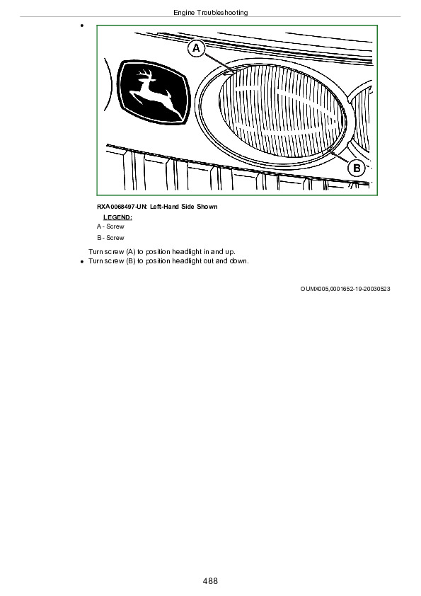
Reference 240-15-049, Left Head Light Circuit Test….2138
Reference 240-15-050, Right Head Light Circuit Test….2154
Reference 240-15-080, Front Wiper Switch Circuit Test….2170
Reference 240-15-081, Front Wiper Motor Circuit Test….2178
Reference 240-15-082, Front Washer Pump Circuit Test….2183
Reference 240-15-083, Rear Wiper Switch Circuit Test….2187
Reference 240-15-084, Rear Wiper Motor Circuit Test….2193
Reference 240-15-085, Rear Washer Pump Circuit Test….2197
Reference 240-15-086, Mirror Adjustment Switch Circuit Test….2201
Reference 240-15-088, Mirror Adjustment Motor Circuit Test….2215
Group 20: Theory Of Operation….1893
Reference 240-20-206, Auxiliary Power Strip Theory Of Operation….2230
Reference 240-20-207, Lighter Theory Of Operation….2231
Reference 240-20-209, Convenience Outlet Theory Of Operation….2232
Reference 240-20-210, Junction Block Theory Of Operation….2233
Reference 240-20-212, Warning Horn Theory Of Operation….2234
Reference 240-20-213, Dome Lamp Theory Of Operation….2235
Reference 240-20-215, Left Door Switch Theory Of Operation….2236
Reference 240-20-216, Console Lamp Theory Of Operation….2237
Reference 240-20-217, Horn Theory Of Operation….2238
Reference 240-20-219, CB Prewire Theory Of Operation….2239
Reference 240-20-220, Radio Theory Of Operation….2240
Reference 240-20-221, Power Mirror Theory Of Operation….2241
Reference 240-20-222, Front and Rear Wiper Theory Of Operation….2242
Reference 240-20-223, Starting and Charging System Theory Of Operation….2243
Reference 240-20-224, Lighting Theory of Operation….2244
Group 25: Functional Schematics….1894
Referência 240-25-001, Functional Schematics Listing….2247
Referência 240-25-100, Schematic and Component Identification Legend….2248
Referência 240-25-102A, SE01 – Starting and Charging Circuits – 7185J and 7205J….2253
Referência 240-25-102B, SE01 – Starting and Charging Circuits – 7195J, 7210J and 7225J….2255
Referência 240-25-103, SE02 – Standard Seat Circuits….2257
Referência 240-25-105A, SE03 – Wiper Circuits – 7185J and 7205J….2258
Referência 240-25-105B, SE03 – Wiper Circuits – 7195J, 7210J and 7225J….2260
Referência 240-25-106A, SE04 – Manual A/C Circuits – 7185J and 7205J….2262
Referência 240-25-106B, SE04 – Manual A/C Circuits – 7195J, 7210J and 7225J….2264
Referência 240-25-108A, SE05 – Radio, Dome Lamp and Multi-Function Switch Circuits – 7185J and 7205J….2266
Referência 240-25-108B, SE05 – Radio, Dome Lamp and Multi-Function Switch Circuits – 7195J, 7210J and 7225J….2268
Referência 240-25-109, SE06A – Turn Signal and Tail Light Circuits….2270
Referência 240-25-111A, SE06C – Programmable Light Circuits – 7185J and 7205J….2272
Referência 240-25-111B, SE06C – Programmable Light Circuits – 7195J, 7210J and 7225J….2274
Referência 240-25-113, SE07 – Accessory Connector Circuits….2276
Referência 240-25-116, SE08 – CAN Termination Circuits….2278
Referência 240-25-118, SE09 – Corner Post Display and CommandCenter Display (ICU)….2279
Referência 240-25-122A, SE10 – Multifunction Control Unit – 7185J and 7205J….2280
Referência 240-25-122B, SE10 – Multifunction Control Unit – 7195J, 7210J and 7225J….2282
Referência 240-25-123, SE10 – Multifunction Control Unit (ACU Functions)….2284
Referência 240-25-124, SE10 – Multifunction Control Unit (CAB Functions)….2286
Referência 240-25-125A, SE10 – Multifunction Control Unit (CCU Functions) – 7185J and 7205J….2287
Referência 240-25-125B, SE10 – Multifunction Control Unit (CCU Functions) – 7195J, 7210J and 7225J….2289
Referência 240-25-126, SE10 – Multifunction Control Unit (HCU Functions)….2291
Referência 240-25-127, SE10 – Multifunction Control Unit (PTQ Functions)….2292
Referência 240-25-145A, SE16B – 6.8L Engine Control Unit – 7185J and 7205J….2294
Referência 240-25-145B, SE16B – 6.8L Engine Control Unit – 7195J, 7210J and 7225J….2296
Referência 240-25-146, SE17 – JDLINK JDLINK is a trademark of Deere & Company Control Unit….1895
Referência 240-25-147A, SE18 – Tractor Equipment Control Unit – 7185J and 7205J….2298
Referência 240-25-147B, SE18 – Tractor Equipment Control Unit – 7195J, 7210J and 7225J….2299
Referência 240-25-148, SE19 – AutoTrac Control Unit….2300
Referência 240-25-221, Belt Line Flood Light Diagnostic Wiring Diagram….2302
Referência 240-25-222, Rear Fender Flood Light Diagnostic Wiring Diagram….2303
Referência 240-25-223, Side Roof Flood Light Diagnostic Wiring Diagram….2304
Referência 240-25-224, Rear Roof Flood Light Diagnostic Wiring Diagram….2305
Referência 240-25-225, Rotary Beacon Light Diagnostic Wiring Diagram….2306
Referência 240-25-226, Front Left Inner Flood Light Diagnostic Wiring Diagram….2307
Referência 240-25-227, Front Right Inner Flood Light Diagnostic Wiring Diagram….2309
Referência 240-25-228, Front Left Outer Flood Light Diagnostic Wiring Diagram….2311
Referência 240-25-229, Front Right Outer Flood Light Diagnostic Wiring Diagram….2313
Referência 240-25-230, Left Tail Light Diagnostic Wiring Diagram….2315
Referência 240-25-231, Right Tail Light Diagnostic Wiring Diagram….2316
Referência 240-25-232, Left Tail Light Diagnostic Wiring Diagram….2317
Referência 240-25-233, Right Tail Light Diagnostic Wiring Diagram….2318
Referência 240-25-234, Left Extremity Transport Light Diagnostic Wiring Diagram….2319
Referência 240-25-235, Right Extremity Transport Light Diagnostic Wiring Diagram….2320
Referência 240-25-236, Left Front Roof Warning Light Diagnostic Wiring Diagram….2321
Referência 240-25-237, Right Front Roof Warning Light Diagnostic Wiring Diagram….2322
Referência 240-25-238, Left Rear Roof Warning Light Diagnostic Wiring Diagram….2323
Referência 240-25-239, Right Rear Roof Warning Light Diagnostic Wiring Diagram….2324
Referência 240-25-240, Left Fender Turn Signal Diagnostic Wiring Diagram….2325
Referência 240-25-241, Right Fender Turn Signal Diagnostic Wiring Diagram….2326
Referência 240-25-249, Left Head Light Diagnostic Wiring Diagram….2327
Referência 240-25-250, Right Head Light Diagnostic Wiring Diagram….2329
Referência 240-25-253, Left Loader Head Light Diagnostic Wiring Diagram….2331
Referência 240-25-254, Right Loader Head Light Diagnostic Wiring Diagram….2333
Referência 240-25-271, Belt Line Flood Lights Relay (K23) Diagnostic Wiring Diagram….2335
Referência 240-25-272, Rear Fender Flood Lights Relay (K3) Diagnostic Wiring Diagram….2336
Referência 240-25-273, Side Roof Flood Lights Relay (K19) Diagnostic Wiring Diagram….2337
Referência 240-25-274, Rear Roof Flood Lights Relay (K21) Diagnostic Wiring Diagram….2339
Referência 240-25-275, Inner Flood Lights Relay (K1) Diagnostic Wiring Diagram….2341
Referência 240-25-276, Outer Flood Lights Relay (K4) Diagnostic Wiring Diagram….2343
Referência 240-25-277, Tail Lights Relay (K6) Diagnostic Wiring Diagram….2345
Referência 240-25-278, Left Turn Signal Relay (K9) Diagnostic Wiring Diagram….2346
Referência 240-25-279, Right Turn Signal Relay (K8) Diagnostic Wiring Diagram….2347
Referência 240-25-282, Fender Enable Relay (K10) Diagnostic Wiring Diagram….2348
Referência 240-25-283, Low Beam Head Light Relay (K12) Diagnostic Wiring Diagram….2349
Referência 240-25-284, High Beam Head Light Relay (K14) Diagnostic Wiring Diagram….2351
Referência 240-25-285, Loader Low Beam Head Light Relay (K13) Diagnostic Wiring Diagram….2353
Referência 240-25-286, Loader High Beam Head Light Relay (K15) Diagnostic Wiring Diagram….2355
Referência 240-25-406, Auxiliary Power Strip Diagnostic Wiring Diagram….2357
Referência 240-25-407, Lighter Diagnostic Wiring Diagram….2359
Referência 240-25-408, Backup Alarm Diagnostic Wiring Diagram….2360
Referência 240-25-409, Convenience Outlet Diagnostic Wiring Diagram….2362
Referência 240-25-410, Junction Block Diagnostic Wiring Diagram….2364
Referência 240-25-412, Warning Horn Diagnostic Wiring Diagram….2366
Referência 240-25-413, Dome Lamp Diagnostic Wiring Diagram….2368
Referência 240-25-415, Left Door Switch Diagnostic Wiring Diagram….2369
Referência 240-25-416, Console Light Diagnostic Wiring Diagram….2370
Referência 240-25-417, Horn Diagnostic Wiring Diagram….2372
Referência 240-25-419, CB Prewire Diagnostic Wiring Diagram….2374
Referência 240-25-420, Radio Diagnostic Wiring Diagram….2375
Referência 240-25-430, Front Wiper Switch Diagnostic Wiring Diagram….2376
Referência 240-25-431, Front Wiper Motor Diagnostic Wiring Diagram….2378
Referência 240-25-432, Front Washer Pump Diagnostic Wiring Diagram….2380
Referência 240-25-433, Rear Wiper Switch Diagnostic Wiring Diagram….2382
Referência 240-25-434, Rear Wiper Motor Diagnostic Wiring Diagram….2384
Referência 240-25-435, Rear Washer Pump Diagnostic Wiring Diagram….2386
Referência 240-25-436, Intermittent Wiper Enable Relay (K20) Diagnostic Wiring Diagram….2388
Referência 240-25-437, Intermittent Wiper Pulse Relay (K22) Diagnostic Wiring Diagram….2390
Referência 240-25-438, Wiper Circuit Relay (K24) Diagnostic Wiring Diagram….2392
Referência 240-25-439, Power Mirror Diagnostic Wiring Diagram….2394
Referência 240-25-500, Key Switch Diagnostic Wiring Diagram….2396
Referência 240-25-502, Accessory Relay Diagnostic Wiring Diagram….2398
Referência 240-25-503, ELX Relay Diagnostic Wiring Diagram….2399
Referência 240-25-504, ELX Relay Diagnostic Wiring DiagramAlternator Diagnostic Wiring Diagram….2400
Referência 240-25-505, ELX Relay Diagnostic Wiring DiagramStarter Motor Diagnostic Wiring Diagram….2401
Referência 240-25-506, ELX Relay Diagnostic Wiring DiagramNeutral Start Switch Diagnostic Wiring Diagram….2402
Referência 240-25-507, ELX Relay Diagnostic Wiring DiagramStarter Relay Diagnostic Wiring Diagram….2404
Group 30: Connector Information – 7185J and 7205J….1897
Wire Colors and Code Numbers….2625
A001 — Fuse and Relay Wire Numbers….2626
A101 — Cab/Steering Column Module….2631
A111 (J1) — Multifunction Control Unit….2633
A111 (J2) — Multifunction Control Unit….2635
A111 (J3) — Multifunction Control Unit….2638
A210 — A/C Compressor Clutch / Diode Assembly….2640
A240 — Radio….2642
A440 — ECU Controller (DE 10)….2426
A670 — Reverser Module….2651
A700 (J1) — Autotrac Control Unit….2653
A700 (J2) — Autotrac Control Unit….2655
A700 (J3) — Autotrac Control Unit….2658
A701 — Steering Valve….2660
A901 — Infocenter Display….2661
A903 — Corner Post Display….2663
A906 — Reconfigurable Display….2664
A908 — GPS Receiver….2666
A914 — Implement Can Terminating Device….2668
A920 — Brake Switches….2669
B240 — Right Front Speaker….2670
B241 — Left Front Speaker….2671
B242 — Right Rear Speaker….2672
B243 — Left Rear Speaker….2673
B301 — Hand Throttle….2674
B302 — Fuel Level Sensor….2675
B303 — Water in Fuel Sensor….2676
B440 — Engine Oil Pressure Sensor….2677
B441 — Fuel Temperature Sensor….2678
B442 — Coolant Temperature Sensor….2679
B443 — Manifold Air Temperature Sensor….2680
B444 — Engine Crank Sensor….2681
B445 — Engine Air Filter….2682
B500 — Wheel Speed….2687
B501 — Rear PTO Speed….2688
B510 — Transmission Oil Pressure Sensor….2689
B513 — Clutch Pedal….2690
B573 — Rear PTO Oil Temperature….2691
B576 — Top Shaft Speed….2692
B670 — Foot Throttle….2693
B671 — Enable Pressure….2694
B700 — Hydraulic Oil Temperature Sensor….2695
B704 — Steering Input Device 1….2696
B705 — Steering Input Device 2….2697
B830 — Rear Hitch….2698
B870 — Rockshaft Position….2699
B871 — Draft Position….2700
B913 — Breakaway….2701
B919 — Radar Sensor….2702
B920 — Horn….2703
B921 — Implement Can Connector….2704
B922 — Air Brake Pressure….2705
B923 — ISO Connector….2706
B960 — Wheel Angle Sensor….2707
E100 — Dome Lamp….2710
E101 — Console Light….2711
E130 — Right Tail Light….2712
E131 — Left Tail Light….2713
E132 — Left Fender Extremity Light….2714
E133 — Right Fender Extremity Light….2715
E134 — Left Front Roof Warning….2716
E135 — Right Front Roof Warning….2717
E140 — Left Head Light….2718
E141 — Left Head Light….2719
E165R — Right Brake Light….2720
E165L — Left Brake Light….2721
E166R — Right Beltline Flood Light….2722
E166L — Left Beltline Flood Light….2723
E167 — Right Turn Light….2724
E168 — Left Turn Light….2725
E170 — Front Left Outer Flood Light….2726
E171 — Front Right Outer Flood Light….2727
E174R — Right Rear Fender Flood….2728
E174L — Left Rear Fender Flood….2729
E176L — Left Rear Roof Floods….2730
E176R — Right Rear Roof Floods….2731
FX01 — Fuse Holder….2732
G003 — Alternator….2733
H200 — Warning Horn….2734
H201 — Backup Alarm….2735
J02 — TECU Controller….2736
KA1 — Manual HVAC Circulation Blower Motor Relay….2739
KST — Starter Relay….2740
KX01 — Relay Connector….2741
K100 — Turn Signal Warning Flasher….2742
M210 — Blower Motor….2743
M211 — Pressurizer Blower Motor….2744
M240 — Front Wiper Motor….2745
M241 — Rear Wiper Motor….2746
M242 — Rear Washer Pump….2747
M243 — Front Washer Pump….2748
M301 — Starter Motor….2749
M302 — Lift Pump….2750
R210 — Blower Motor Resistor….2751
S001 — Key Switch….2752
S101 — Hazard Switch….2754
S104 — Dome Lamp Switch….2755
S105R — Right Hand Door Switch….2756
S105L — Left Hand Door Switch….2757
S120 — Road Lights Switch….2758
S121 — Field Lights Switch….2759
S210 — Blower Switch….2760
S211 — A/C On/Off Switch….2761
S212 — A/C Deicing Switch….2762
Section 245: Control Units….2848
Group 05: General References….2848
Reference 245-05-001, Recall, Record, and Clear Codes….2865
Reference 245-05-002, Access Control Unit Addresses….2873
Reference 245-05-003, Diagnostic Trouble Code Listing….2879
Reference 245-05-003A, ACU Code List….2880
Reference 245-05-003D, CAB Code List….2883
Reference 245-05-003E, CCU Code List….2885
Reference 245-05-003F, ECU Code List….2886
Reference 245-05-003H, HCU Code List….2888
Reference 245-05-003I, ICU Code List….2890
Reference 245-05-003J, JDL Code List….2891
Reference 245-05-003M, PTQ Code List….2893
Reference 245-05-003R, TEC Code List….2895
Reference 245-05-003S, SSU Code List….2896
Reference 245-05-004, Control Unit Addresses….2899
Reference 245-05-004A, ACU Address List….2900
Reference 245-05-004D, CAB Address List….2902
Reference 245-05-004E, CCU Address List….2904
Reference 245-05-004F, ECU Address List….2906
Reference 245-05-004H, HCU Address List….2908
Reference 245-05-004I, ICU Address List….2910
Reference 245-05-004J, JDL Address List….2912
Reference 245-05-004M, PTQ Address List….2915
Reference 245-05-004R, TEC and TEI Address List….2917
Reference 245-05-004S, SSU Address List….2919
Reference 245-05-005, Programming Control Units….2921
Reference 245-05-006, CAN Communication Fault Checks….2922
Reference 245-05-007, CAN Network Voltage Checks….2927
Reference 245-05-100, Control Unit Locations and Identification….2936
Reference 245-05-200, CAN Communication System Theory Of Operation….2938
Reference 245-05-201, VIN Security Fault Diagnosis….2944
Reference 245-05-300, CAN Communication System Diagnostic Wiring Diagrams….2946
Reference 245-05-303, PowrQuad-Plus CAN System Diagnostic Wiring Diagram – Cab Harnesses….2947
Reference 245-05-304, PowrQuad-Plus CAN System Diagnostic Wiring Diagram – Engine and Chassis Harnesses….2948
Reference 245-05-305, Chassis CAN Circuit Interconnections….2950
Group 15: Tests and Adjustments….2849
Reference 245-15-001, Control Units Switched Supply Voltage and Ground Test….2953
Reference 245-15-002, Control Units Unswitched Supply Voltage and Ground Test….2955
Group ACU: ACU….2849
Reference 245-ACU-001, Armrest Control Unit Calibration….2968
Reference 245-ACU-002, Armrest Control Unit “Beep” Mode Test….2979
Reference 245-ACU-024, PowrQuad-Plus Hand Throttle Position Sensor Circuit Test….2982
Reference 245-ACU-025, PowrQuad-Plus Rear PTO Switch Circuit Test….2988
Reference 245-ACU-026, PowrQuad-Plus IMS Sequence Switch Circuit Test….2993
Reference 245-ACU-028, PowrQuad-Plus Rear Hitch Control Lever Sensor Circuit Test….2998
Reference 245-ACU-102, PowrQuad-Plus ACU System Relay, Fuse, and Circuit Testing….3004
Reference 245-ACU-201, ACU Control Unit Theory Of Operation….3008
Reference 245-ACU-224, PowrQuad-Plus Hand Throttle Position Sensor Theory Of Operation….3010
Reference 245-ACU-225, PowrQuad-Plus Rear PTO Switch Theory Of Operation….3011
Reference 245-ACU-226, PowrQuad-Plus IMS Sequence Switch Theory Of Operation….3012
Reference 245-ACU-228, PowrQuad-Plus Rear Hitch Control Lever Sensor Theory Of Operation….3013
Reference 245-ACU-302, PowrQuad-Plus ACU System Relay, Fuse, and Circuit Diagnostic Wiring Diagram….3014
Reference 245-ACU-324, PowrQuad-Plus Hand Throttle Position Sensor Diagnostic Wiring Diagram….3016
Reference 245-ACU-325, PowrQuad-Plus Rear PTO Switch Diagnostic Wiring Diagram….3017
Reference 245-ACU-326, PowrQuad-Plus IMS Sequence Switch Diagnostic Wiring Diagram….3019
Reference 245-ACU-328, PowrQuad-Plus Rear Hitch Control Lever Diagnostic Wiring Diagram….3021
Group CAB: CAB….2849
Reference 245-CAB-001, CAB Control Unit Calibration….3041
Reference 245-CAB-002, CAB Control Unit “Beep” Mode Test….3060
CAB — MFWD Switch Circuit Test….3064
Reference 245-CAB-008, Rear Differential Lock Switch Circuit Test….3070
Reference 245-CAB-009, Turn Signal Switch Circuit Test….3075
Reference 245-CAB-010, Hazard Light Switch Circuit Test….3081
Reference 245-CAB-011, Road Light Switch Circuit Test….3087
Reference 245-CAB-012, Field Light Switch Circuit Test (070001—)….3093
Reference 245-CAB-013, Clutch Pedal Position Sensor Circuit Test….3098
Reference 245-CAB-015, PowrQuad-Plus Foot Throttle Position Sensor Circuit Test….3104
Reference 245-CAB-017, PowrQuad-Plus Brake Switch Assembly Circuit Test….3110
Reference 245-CAB-019, High Beam Head Lights Switch Circuit Test….3116
Reference 245-CAB-020, Operator Presence Switch Circuit Test….3122
Reference 245-CAB-021, Intermittent Wiper Switch Circuit Test….3126
Reference 245-CAB-022, Implement Switch Circuit Test….3131
Reference 245-CAB-024, PowrQuad-Plus Left Hand Reverser Switch Assembly Circuit Test….3135
Reference 245-CAB-102, PowrQuad-Plus CAB System Relay, Fuse, and Circuit Testing….3141
Reference 245-CAB-201, CAB Control Unit Theory of Operation….3145
Reference 245-CAB-207, MFWD Switch Theory of Operation….3148
Reference 245-CAB-208, Rear Differential Lock Switch Theory of Operation….3149
Reference 245-CAB-209, Turn Signal Switch Theory of Operation….3150
Reference 245-CAB-210, Hazard Light Switch Theory of Operation….3151
Reference 245-CAB-211, Road Light Switch Theory of Operation….3152
Reference 245-CAB-212, Field Light Switch Theory of Operation (070001—)….3153
Reference 245-CAB-213, Clutch Pedal Position Sensor Theory of Operation….3154
Reference 245-CAB-215, PowrQuad-Plus Foot Throttle Position Sensor Theory of Operation….3155
Reference 245-CAB-217, PowrQuad-Plus Brake Switch Assembly Theory of Operation….3156
Reference 245-CAB-219, High Beam Head Lights Switch Theory of Operation….3157
Reference 245-CAB-220, Operator Presence Switch Theory of Operation….3158
Reference 245-CAB-221, Intermittent Wiper Switch Theory of Operation….3159
Reference 245-CAB-222, Implement Switch Theory of Operation….3160
Reference 245-CAB-224, PowrQuad-Plus Left Hand Reverser Switch Assembly Theory of Operation….3161
Reference 245-CAB-302, PowrQuad-Plus CAB System Relay, Fuse, and Circuit Diagnostic Wiring Diagram….3162
Reference 245-CAB-347, PowrQuad-Plus MFWD Switch Diagnostic Wiring Diagram….3164
Reference 245-CAB-348, PowrQuad-Plus Rear Differential Lock Switch Diagnostic Wiring Diagram….3166
Reference 245-CAB-349, PowrQuad-Plus Turn Signal Switch Diagnostic Wiring Diagram….3167
Reference 245-CAB-350, PowrQuad-Plus Hazard Light Switch Diagnostic Wiring Diagram….3168
Reference 245-CAB-351, PowrQuad-Plus Road Light Switch Diagnostic Wiring Diagram….3170
Reference 245-CAB-352, PowrQuad-Plus Field Light Switch Diagnostic Wiring Diagram (070001—)….3172
Reference 245-CAB-353, PowrQuad-Plus Clutch Pedal Position Sensor Diagnostic Wiring Diagram….3173
Reference 245-CAB-354, PowrQuad-Plus Foot Throttle Position Sensor Diagnostic Wiring Diagram….3174
Reference 245-CAB-355, PowrQuad-Plus Brake Switch Assembly Diagnostic Wiring Diagram….3175
Reference 245-CAB-358, PowrQuad-Plus High Beam Head Lights Switch Diagnostic Wiring Diagram….3176
Reference 245-CAB-359, PowrQuad-Plus Operator Presence Switch Diagnostic Wiring Diagram….3178
Reference 245-CAB-360, PowrQuad-Plus Intermittent Wiper Switch Diagnostic Wiring Diagram….3180
Reference 245-CAB-361, PowrQuad-Plus Implement Switch Diagnostic Wiring Diagram….3182
Reference 245-CAB-362, PowrQuad-Plus Left Hand Reverser Switch Assembly Diagnostic Wiring Diagram….3183
Group CCU: CCU….2851
Reference 245-CCU-001, CCU Control Unit Calibration….3214
Reference 245-CCU-002, Central Control Unit “Beep” Mode Test w/ Speed Sensors….3243
Reference 245-CCU-003, Central Control Unit “Beep” Mode Test w/o Speed Sensors….3246
Reference 245-CCU-004, Rear PTO Speed Sensor Circuit Test….3247
Reference 245-CCU-007, Rear PTO Oil Temperature Sensor Circuit Test….3252
Reference 245-CCU-008, Hydraulic Oil Temperature Sensor Circuit Test….3257
Reference 245-CCU-009, Hydraulic Oil Filter Switch Circuit Test….3262
Reference 245-CCU-010, Air Brake Pressure Sensor Circuit Test….3266
Reference 245-CCU-011, Fuel Level Sensor Circuit Test….3270
Reference 245-CCU-012, Rear Differential Lock Solenoid Circuit Test….3275
CCU — MFWD Solenoid Circuit Test….3278
Reference 245-CCU-014, Rear PTO Solenoid Circuit Test….3281
Reference 245-CCU-015, Buffered Wheel Speed Circuit Test….3285
Reference 245-CCU-016, Radar Sensor Circuit Test….3286
Reference 245-CCU-017, Wheel Speed Sensor Circuit Test….3291
Reference 245-CCU-018, PowrQuad-Plus Rear PTO Switch Circuit Test….3297
Reference 245-CCU-102, PowrQuad-Plus CCU System Relay, Fuse, and Circuit Testing….3302
Reference 245-CCU-201, CCU Control Unit Theory of Operation….3306
Reference 245-CCU-204, Rear PTO Speed Sensor Theory of Operation….3308
Reference 245-CCU-205, Rear PTO Switch Theory of Operation….3309
Reference 245-CCU-207, Rear PTO Oil Temperature Sensor Theory of Operation….3310
Reference 245-CCU-208, Hydraulic Oil Temperature Sensor Theory of Operation….3311
Reference 245-CCU-209, Hydraulic Oil Filter Switch Theory of Operation….3312
Reference 245-CCU-210, Air Brake Pressure Sensor Theory of Operation….3313
Reference 245-CCU-211, Fuel Level Sensor Theory of Operation….3314
Reference 245-CCU-212, Rear Differential Lock Solenoid Theory of Operation….3315
Reference 245-CCU-213, MFWD Solenoid Theory of Operation….3316
Reference 245-CCU-214, Rear PTO Solenoid Theory of Operation….3317
Reference 245-CCU-215, Buffered Wheel Speed Theory of Operation….3318
Reference 245-CCU-216, Radar Sensor Theory of Operation….3319
Reference 245-CCU-217, Wheel Speed Sensor Theory of Operation….3321
Reference 245-CCU-302, PowrQuad-Plus CCU System Relay, Fuse, and Circuit Diagnostic Wiring Diagram….3322
Reference 245-CCU-334, PowrQuad-Plus Rear PTO Speed Sensor Diagnostic Wiring Diagram….3324
Reference 245-CCU-335, PowrQuad-Plus Rear PTO Switch Diagnostic Wiring Diagram….3326
Reference 245-CCU-337, PowrQuad-Plus Rear PTO Oil Temperature Sensor Diagnostic Wiring Diagram….3328
Reference 245-CCU-338, PowrQuad-Plus Hydraulic Oil Temperature Sensor Diagnostic Wiring Diagram….3330
Reference 245-CCU-339, PowrQuad-Plus Hydraulic Oil Filter Switch Diagnostic Wiring Diagram….3332
Reference 245-CCU-340, PowrQuad-Plus Air Brake Pressure Sensor Diagnostic Wiring Diagram….3334
Reference 245-CCU-341, PowrQuad-Plus Fuel Level Sensor Diagnostic Wiring Diagram….3336
Reference 245-CCU-342, PowrQuad-Plus Rear Differential Lock Solenoid Diagnostic Wiring Diagram….3338
Reference 245-CCU-343, PowrQuad-Plus MFWD Solenoid Diagnostic Wiring Diagram….3340
Reference 245-CCU-344, PowrQuad-Plus Rear PTO Solenoid Diagnostic Wiring Diagram….3341
Reference 245-CCU-345, PowrQuad-Plus Buffered Wheel Speed Signal Diagnostic Wiring Diagram….3342
Reference 245-CCU-346, PowrQuad-Plus Radar Sensor Diagnostic Wiring Diagram….3344
Reference 245-CCU-347, PowrQuad-Plus Wheel Speed Sensor Diagnostic Wiring Diagram….3346
Group ECU: ECU….2852
Reference 245-ECU-001, Vistronic Fan Speed Control Solenoid and Circuit Test….3351
Reference 245-ECU-002, Vistronic Fan Speed Sensor Test….3354
Group HCU: HCU….2852
Reference 245-HCU-001, HCU Control Unit Calibration….3373
Reference 245-HCU-002, Hitch Control Unit “Beep” Mode Test….3389
Reference 245-HCU-004, Rear Hitch Raise Solenoid Circuit Test….3392
Reference 245-HCU-005, Rear Hitch Lower Solenoid Circuit Test….3397
Reference 245-HCU-006, Rear Hitch Left External Switch Circuit Test….3402
Reference 245-HCU-011, PowrQuad-Plus Rear Hitch Position Sensor Circuit Test….3408
Reference 245-HCU-012, PowrQuad-Plus Rear Hitch Draft Sensor Circuit Test….3414
Reference 245-HCU-013, PowrQuad-Plus Rear Hitch Control Lever Sensor Circuit Test….3420
Reference 245-HCU-102, PowrQuad-Plus HCU System Relay, Fuse, and Circuit Testing….3426
Reference 245-HCU-201, HCU Control Unit Theory Of Operation….3430
Reference 245-HCU-204, Rear Hitch Raise Solenoid Theory Of Operation….3432
Reference 245-HCU-205, Rear Hitch Lower Solenoid Theory Of Operation….3433
Reference 245-HCU-206, Rear Hitch Left External Switch Theory Of Operation….3434
Reference 245-HCU-208, Rear Hitch Position Sensor Theory Of Operation….3435
Reference 245-HCU-209, Rear Hitch Draft Sensor Theory Of Operation….3436
Section 255: PowrQuad™ PLUS Transmission….3881
Group 05: General Information….1567
Reference 255-05-001, Install Test Equipment….3893
Group 10: Operational Checks….3881
Reference 255-10-001, PowrQuad-Plus Transmission Preliminary Checks….3905
Reference 255-10-002, Transmission Operational Checks….3907
Group 15: Tests and Adjustments….3881
Reference 255-15-001, Driving And Preliminary Pressure Test….3915
Reference 255-15-002, Differential Lock Circuit Leak Test….3918
Reference 255-15-003, MFWD Leak Test….3921
Reference 255-15-004, Rear PTO Leak Test….3924
Reference 255-15-005, Transmission Element Leak Test….3931
Reference 255-15-006, Lube Pressure Test….3937
Reference 255-15-007, System Pressure Test….3939
Reference 255-15-008, Pump Air Leak Test….3941
Reference 255-15-009, Transmission Pump / Cooler Flow And Valve Test….3944
Reference 255-15-010, Clutch Cooling Circuit Test….3948
Reference 255-15-011, Air Pump Vacuum Test….3950
Reference 255-15-012, Clutch and Brake Element Air Leak Test….3952
Reference 255-15-013, Clutch Enable Pressure Test….3955
Reference 255-15-014, Element Leak Test….3958
Group 20: Theory of Operation….3881
Reference 255-20-001, PowrQuad-Plus Transmission Theory Of Operation….3968
Reference 255-20-002, Start-in-Gear and Left Hand Reverser Operation….3971
Reference 255-20-003, Planetary Operation….3973
Reference 255-20-004, Pumps And Oil Circuits….3975
Reference 255-20-005, Reservoir And Valves Pressurization Chart….3985
Reference 255-20-006, Shifting Theory Of Operation….3986
Reference 255-20-007, Range Box Operation….3994
Group 25: Schematics and Diagrams….3881
Reference 255-25-001, PowrQuad-Plus System Schematic and Diagram Listing….3997
Reference 255-25-002, Transmission Schematic….3998
Reference 255-25-003, Transmission Front View Test Port and Component Locations….4002
Reference 255-25-004, Transmission Right View Test Port and Component Locations….4004
Reference 255-25-005, Transmission Bottom View Test Port and Component Locations….4006
Section 256: Drive Systems….4008
Group 10: Preliminary And Operational Checks….4008
Reference 256-10-001, Preliminary Checks….4011
Reference 256-10-002, Rear Differential Lock Operational Check….4013
Reference 256-10-003, MFWD Operational Checks….4014
Reference 256-10-004, PTO Operational Check….4015
Group 15: Test References….4008
Reference 256-15-001, MFWD Clutch Test….4021
Reference 256-15-002, MFWD Clutch Slippage Test….4028
Reference 256-15-002, MFWD Clutch Slippage Test….4028
Reference 256-15-004, Rear PTO Modulating Valve Test….4030
Group 20: Theory Of Operation….4008
Reference 256-20-001, Rear Differential Theory Of Operation….4036
Reference 256-20-002, MFWD Theory Of Operation….4038
Reference 256-20-005, Rear PTO Theory Of Operation….4041
Group 25: Schematics and Diagrams….4008
Reference 256-25-001, Drive Systems Schematics and Diagrams Listing….4046
Reference 256-25-002, Differential Lock Schematic….4047
Reference 256-25-003, MFWD Schematic….4048
Reference 256-25-004, PTO Schematic….4049
Section 260: Steering and Brakes….4050
Group 05: Preliminary Checks….4050
Reference 260-05-001, AutoTrac Steering System Preliminary Check….4053
Group 10: Preliminary And Operational Checks….4050
Reference 260-10-001, Rear Brakes Preliminary Check….4055
Reference 260-10-002, Rear Brake Operational Test….4056
Reference 260-10-003, Steering Preliminary Check….4058
Reference 260-10-004, Steering Operational Check….4059
Reference 260-10-007, AutoTrac Steering System Operational Check….4060
Group 15: Test And Adjustments….4050
Reference 260-15-001, Bleed Rear Brakes….4064
Reference 260-15-002, Rear Brake Pressure Test….4066
Reference 260-15-003, Rear Brake Valve Leak Test….4068
Reference 260-15-004, Steering Leak Test….4069
Reference 260-15-005, Rear Brake Pressure Sensor Signal Test….4071
Reference 260-15-011, Air Brake Pressure Test….4073
Reference 260-15-013, AutoTrac Steering Accuracy Check….4076
Reference 260-15-014, Electro-Hydraulic Steering Valve Test….4078
Reference 260-15-015, Electro-Hydraulic Steering Valve Manual Test….4081
Reference 260-15-016, Wheel Angle Sensor – Flowmeter Inspection and Disconnected Operational Test (—070000)….4084
Group 20: Theory Of Operation….4050
Reference 260-20-100, Steering and Brakes Reference Listing….4086
Reference 260-20-101, Steering Valve Theory of Operation….4087
Reference 260-20-102, Gerotor Theory of Operation….4089
Reference 260-20-103, Steering Cylinder Theory of Operation….4092
Reference 260-20-110, Brake Valve Theory….4093
Reference 260-20-111, Brake Pistons, Plates and Disks Operation….4094
Reference 260-20-112, Air Trailer Brake Theory Of Operation….4096
Group 25: Schematics and Diagrams….4050
Reference 260-25-001, Steering and Brakes Schematics and Diagrams Listing….4101
Reference 260-25-002, AutoTrac Schematic….4102
Reference 260-25-003, Steering Schematic….4104
Reference 260-25-004, Brake Schematic….4105
Reference 260-25-010, Single Gerotor Steering Pump Cross Section….4108
Reference 260-25-011, Dual Gerotor Steering Pump Cross Section….4110
Section 270: Hydraulics….4112
Group 05: General References….4112
Reference 270-05-001, Install Test Equipment….4122
Reference 270-05-002, Heat Hydraulic Oil….4130
Group 10: Operational and Preliminary Checks….4112
Reference 270-10-001, Hydraulic System Preliminary Checks….4133
Reference 270-10-002, Hydraulic System Operational Checks….4135
Reference 270-10-003, Rear Hitch Operational Checks….4138
Group 15: Tests and Adjustments….4112
Reference 270-15-001, Main Pump Inlet Pressure Test….4142
Reference 270-15-002, Main Pump Standby Pressure Test….4144
Reference 270-15-003, Pump Pressure Above Standby Or Near Stall….4146
Reference 270-15-004, Preliminary Main Pump Pressure Test….4149
Reference 270-15-005, Load-Sense Valve Test….4152
Reference 270-15-006, Bleeding Load-Sense and Hydraulic Pressure Circuits….4154
Reference 270-15-007, Charge Pump Suction Air Leak Test….4156
Reference 270-15-008, Hydraulic System Leakage Test….4158
Reference 270-15-009, System Response to A Missing Shuttle Check Valve….4162
Reference 270-15-010, Main Pump Stall Pressure Test….4165
Reference 270-15-011, Main Pump Inlet Pressure Test (Pump At Full Flow)….4168
Reference 270-15-012, Neutral Load-Sense Pressure Test….4170
Reference 270-15-013, Pump Load-Sense Preliminary Pressure Test….4176
Reference 270-15-014, Primary Circuit Pressure Test….4178
Reference 270-15-015, Priority Valve Operational Pressure Test….4181
Reference 270-15-016, Priority Valve Differential Pressure Test….4183
Reference 270-15-017, Main Pump Flow Test….4185
Reference 270-15-018, Pump Load-Sense “Differential” Pressure Test….4191
Reference 270-15-019, Rear SCV Pilot Pressure Test….4194
Reference 270-15-020, Pump Pressure Verification Test….4196
Reference 270-15-023, SCV Leak Down Test….4198
Group 20: Theory Of Operation….4112
Reference 270-20-100, Hydraulic System Theory Of Operation….4206
Reference 270-20-101, Selective Control Valve Theory of Operation….4212
Reference 270-20-103, Rear Hitch Theory of Operation….4232
Group 25: Schematics and Diagrams….4113
Reference 270-25-001, Hydraulic System Schematic and Diagram Listing….4243
Reference 270-25-010, Priority Valve Component Locations….4244
Reference 270-25-101, PowrQuad PLUS Hydraulic System Schematic….4248
Reference 270-25-102, Rear SCV Stack Schematic….4250
Section 290: Operator Station….4252
Group 05: Preliminary Checks….4252
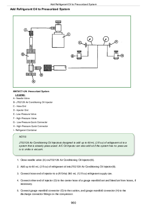
Reference 290-05-001, A/C System Preliminary Checks….4255
Group 10: Operational Checks….4252
Reference 290-10-003, Manual Seat Operational Check….4258
Reference 290-10-004, Manual Air Conditioning Operational Checks….4259
Group 15: Tests and Adjustments….4252
Reference 290-15-001, Install Test Equipment….4268
Reference 290-15-002, System Static Pressure Test….4270
Reference 290-15-008, Summary of A/C Testing….4277
Reference 290-15-009, A/C System Moisture Removal Procedure….4278
Reference 290-15-016, Standard Seat Height Control Switch Circuit Test….4280
Reference 290-15-017, Standard Seat Compressor Assembly Circuit Test….4285
Reference 290-15-018, Standard Seat Diode Circuit Test….4290
Reference 290-15-019, Manual HVAC Circulation Blower Motor Circuit Test….4293
Reference 290-15-020, Manual HVAC Pressurizer Blower Motor Circuit Test….4297
Reference 290-15-021, Manual HVAC Compressor Clutch Engagement and Cycle Test….4299
Reference 290-15-022, Manual HVAC System Pressure Check….4311
Reference 290-15-023, Manual HVAC Temperature Drop Check….4320
Group 20: Theory Of Operation….4252
Reference 290-20-001, Manual Air Conditioning Theory of Operation….4331
Reference 290-20-003, Manual Seat Theory Of Operation….4337
Group 25: Schematics and Diagrams….4252
Reference 290-25-003, Manual Seat Suspension Diagnostic Wiring Diagram….4341
Reference 290-25-019, Blower Motor Switch Diagnostic Wiring Diagram….4343
Reference 290-25-020, Manual HVAC Circulation Blower Motor Diagnostic Wiring Diagram….4345
Reference 290-25-021, Manual HVAC Pressurizer Blower Motor Diagnostic Wiring Diagram….4347
Reference 290-25-022, A/C On / Off Switch Diagnostic Wiring Diagram….4348
Reference 290-25-023, Air Conditioning De-icing Switch Diagnostic Wiring Diagram….4350
Reference 290-25-024, A/C Dual Pressure Switch Diagnostic Wiring Diagram….4352
Reference 290-25-025, A/C Compressor Clutch / Diode Assembly Diagnostic Wiring Diagram….4354
Reference 290-25-026, Blower Motor Resistor Diagnostic Wiring Diagram….4356
Section 299: Service Tools….4358
Group 05: Dealer Fabricated Tools….4358
DFRW2 — Hose Assembly….4364
DFRW26 — Test Lead For Automotive-Style Fuses….4366
DFRW51—Electronic Circuit Load Tester….4367
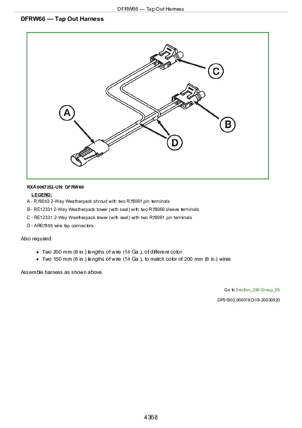
DFRW66 — Tap Out Harness….4368
DFRW 88 — Clutch Torque Tool….4369
DFRW126—Modified Tap Out Harness….4371
DFRW176—AutoTrac Steering Valve Test Harness….4373
DFRW177 — Element Test Plate….4378
DFRW180 — Vistronic Fan Tap Out Harness….4380
DFRW191 — Red Glad Hand Assembly….4382
DFRW192 — Blue Glad Hand Assembly….4383
Group 10: Service Tools and Kits….4358
38H1033 — -12 ORFS Tee….4385
38H1272 — -12 ORFS Union….4386
38H1278 — -6 ORFS Union….4387
38H1281 — -16 ORFS Union….4388
38H1415 — -6 ORFS Cap….4389
38H1419 — -16 ORFS Cap….4390
AR93820 — ISO Hose Fitting….4391
AR94522 — ISO SCV Coupler….4392
D01074AA — 75 GPM In-Line, Dual Scale Hydraulic Tester….4393
D01169AA — Hydraulic Tester….4394
D05330ST — Supplemental Accessory Kit….4395
D05361ST — Rubber Stopper/Leak Detector Kit….4396
D15032NU — Vacuum Pump Kit….4397
JDG774 — Solenoid Test Harness….4398
JDG10466 — Flex Probe Kit….4399
JDG1424 — Support Block….4400
JDG1478—Digital Multimeter….4401
JT01767 — Supplemental Lawn and Grounds Care Products Hydraulic Fitting Kit….4402
JT02016 — Electrical Diagnostic Receptacle Kit….4403
JT02051 — Manifold with Gauges….4404
JT02063 — Electronic Leak Detector….4405
JT02081—Halogen Leak Detector….4406
JT02095 — R134a Start-Up Kit….4407
JT02098 — Air Conditioning Flushing Kit….4408
JT02148 — Straight Connector (M10 x 1.25M or 1/2-16 ACME)….4409
JT02153 — Current Clamp-On Probe….4410
JT02178 — A/C Leak Detection Kit….4411
JT02219 — Fitting Straight, 1/8 NPTF x 1/2-16 ACME….4412
JT03232 — Connector 1/4 M NPT X 1/8 F NPT….4413
JT03261 — Diagnostic Receptacle 1/4 M NPT….4414
JT03412 — Supplemental Pressure Test Kit….4415
JT03413 — Supplemental Flow Test Kit….4416
JT03437 — Plug x Socket – 90° Coupler….4417
JT03445 — Straight Fitting, (9/16-18 M 37° or M14 X 1.5 M ORB)….4418
JT03475 — Tee Fitting….4419
JT03485 — Special Male Quick Coupler (1/8 Male QC x 1 3/16 – 12 UN Female)….4420
JT03512 — Hydraulic Fitting Kit….4421
JT03512-1 — 90° Elbow (1 1/16-12 (m) JIC x -12 (f) ORFS)….4422
JT05412 — Industrial Universal Pressure Test Kit….4423
JT05418 — Industrial Flow Test Kit….4424
JT05470 — Universal Pressure Test Kit….4425
JT05472 — Gauge w/Quick Coupler, 0-400 kPa (0-60 psi)….4426
JT05473 — Gauge w/Quick Coupler, 0-35000 kPa (0-350 bar; 0-5000 psi)….4427
JT05474 — Gauge w/Quick Coupler, 0-2000 kPa (0-20 bar; 0-290 psi)….4428
JT05475 — Gauge, 0-400 kPa (0-4 bar; 0-60 psi)….4429
JT05476 — 90° Elbow, 1/4 Male Quick Coupler x 7/16-20 F 37° Sw DR….4430
JT05478A — 90° Elbow 14 mm M X 14 mm F….4431
JT05480 — Diagnostic Receptacle (M14 x 1.5M ORB x 1/2 Quick Coupler)….4432
JT05494 — Hydraulic Fitting 7/16-20 M 37° x 3/4-16 M ORB….4433
JT05497 — Hose Assembly, 3048 mm (120 in.) Long….4434
JT05690 — Straight Fitting (1 1/16-12 M 37° x 1 3/16-12 F ORFS)….4435
JT05697A — U-Tube Manometer Kit….4436
JT05791 — Digital Multimeter….4437
JT05832 — Battery Load Tester….4438
JT05833 — Battery Service Kit….4439
JT05843 — Hydrometer….4440
JT07030 — (100)/0/200 kPa ((1)/0/2 bar) (30 Hg./0/30 psi) Vacuum / Pressure Gauge….4441
JT07041 — 0-2,800 kPa (0-28 bar) (0-400 psi) Hydraulic Pressure Gauge….4442
JT07115 — Master Hydraulic Test Kit….4443
JT07115 SUP — Supplemental Master Hydraulic Test Kit….4444
JT07117 — Three-Gauge Manifold….4445
JT07118 — Two-Valve Manifold….4446
JT07119 — 5 ft. Test Hose….4447
JT07120 — Load Valve Assembly….4448
JT07134 — Bleed Pipe….4449
JT07135 — Special Hose….4450
JT07196 — Technicians A/C R134a Service Kit….4451
JT07207 — Gauge 500 kPa (5 bar; 60 psi)….4452
JT07209 — Hydraulic Test Kit….4453
JT07260 — ORFS Adapter Hydraulic Test Kit….4454
JT07328 — Terminal Test Kit….4455
JT07328-1 — Grey Male Test Terminal….4456
JT07328-2 — Grey Female Test Terminal….4457
JT07328-3 — Violet Male Test Terminal….4458
JT07328-4 — Violet Female Test Terminal….4459
JT07328-5 — Brown Male Test Terminal….4460
JT07328-6 — Brown Female Test Terminal….4461
JT07328-7 — Orange Male Test Terminal….4462
JT07328-8 — Orange Female Test Terminal….4463
JT07328-9 — Dark Blue Male Test Terminal….4464
JT07328-10 — Dark Blue Female Test Terminal….4465
JT07328-11 — Red Male Test Terminal….4466
JT07328-12 — Red Female Test Terminal….4467
JT07328-13 — Yellow Male Test Terminal….4468
JT07328-14 — Yellow Female Test Terminal….4469
JT07328-15 — Green Male Test Terminal….4470
JT07328-16 — Green Female Test Terminal….4471
JT07328-17 — Black Male Test Terminal….4472
JT07328-18 — Black Female Test Terminal….4473
JT07328-19 — Patch Cords….4474
R77464 — Pin Terminal….4475
RE190805 — Diagnostic Receptacle….4476
RE60701 — Diagnostic Receptacle….4477
T57553 — Special Nut….4478
John Deere Models 7185J, 7195J, 7205J, 7210J, 7225J Tractors Repair Service Manual (TM802019)
INSTANT DOWNLOAD