INSTANT DOWNLOAD
Complete Diagnistics, Operation and Test manual with electrical wiring diagrams for John Deere 9560 and 9660 Combines (SN. 705201-), with workshop information to maintain, diagnose, and rebuild.
John Deere 9560, 9660 Combines workshop Operation and Test manual includes:
* Numbered table of contents easy to use so that you can find the information you need fast.
* Detailed sub-steps expand on repair procedure information
* Numbered instructions guide you through every repair procedure step by step.
* Troubleshooting and electrical service procedures are combined with detailed wiring diagrams for ease of use.
* Notes, cautions and warnings throughout each chapter pinpoint critical information.
* Bold figure number help you quickly match illustrations with instructions.
* Detailed illustrations, drawings and photos guide you through every procedure.
* Enlarged inset helps you identify and examine parts in detail.
TM2162 – John Deere 9560 and 9660 Combines Technical manual (Diagnosis and Tests).pdf
Total Pages: 6,038 pages
File Format: PDF (PC/Mac/Android/Kindle/iPhone/iPad; bookmarked, ToC, Searchable, Printable)
Language: English
MAIN SECTIONS
Foreword
General
Safety
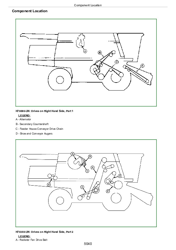
Combine and Component Identification
General Specifications
Diagnostic and Testing Procedures
Diagnostic Trouble Codes
Accessing Diagnostic Trouble Codes and Addresses
A00 – Engine Control Unit Diagnostic Trouble Codes
C00 – Armrest Control Unit Diagnostic Trouble Codes
C03 – Cornerpost Control Unit Diagnostic Trouble Codes
Calibration Error Codes
E00 – Tailings Master Sensor Diagnostic Trouble Codes
E01 – Header Control Unit Diagnostic Trouble Codes
E02 – Right Control Unit Diagnostic Trouble Codes
E03 – Left Control Unit Diagnostic Trouble Codes
E15 – Control Unit E15 Diagnostic Trouble Codes
ECU – Engine Control Unit Diagnostic Trouble Codes
GREENSTAR Display Warning Messages and Fault Codes
GREENSTAR Data Card Warning Messages
GREENSTAR Mobile Processor Warning Messages
GREENSTAR Moisture Sensor Diagnostic Trouble Codes
HARVEST DOC Warning Messages
Control Unit SSU Last Exit Codes
Control Unit SSU Diagnostic Trouble Codes
STARFIRE iTC Diagnostic Trouble Codes
STARFIRE Receiver Warning Messages
Terrain Compensation Module Fault Codes
UIM – External Display Codes
VTi – GREENSTAR Display 2100/2600
Observable Symptoms
Engine System
Air Intake and Cooling Systems
Electrical
Power Train System
Four Wheel Drive System
Brake System
Hydraulic System
Main Gearcase System
Steering System
CLIMATRAK System
Separator System
Engine System
General Information
Test Procedures and Adjustments
Engine Type Identification
Engine Diagnostics – Type A
Engine Diagnostics – Type B
Component Identification and Location
Air Intake and Cooling Systems
General Information
Test Procedures and Adjustments
Air Intake System Diagnostics
Engine Cooling Package Diagnostics
Component Identification and Location
Electrical System
How To Use This Diagnostic Information
Accessing Diagnostic Trouble Codes and Addresses
Calibration Procedures
Diagnostic Trouble Codes, Warning Messages and Fault Codes
Diagnostic Addresses By Controller
Machine Setting Addresses
Active Header Height Control Diagnostics – Type Identification
Active Header Height Control Diagnostics – Type A
Active Header Height Control Diagnostics – Type B
Active Header Height Control Diagnostics – Type C
Active Header Height Control Diagnostics – Type D
Alternator Type Identification
Alternator and Battery Diagnostics – Type A
Alternator and Battery Diagnostics – Type B
Armrest Control Unit – Overall Diagnostics
Auxiliary Power Strip Outlet Diagnostics
Backup Alarm Diagnostics
CAN Bus Type Identification
CAN Bus 1 Diagnostics – Type A
CAN Bus 1 Diagnostics – Type B
CAN Bus 2 Diagnostics
Cleaning Fan Speed Adjust Diagnostics
CLIMATRAK iagnostics
COMFORT COMMAND eat Diagnostics
CONTOUR MASTER Automatic Tilt Diagnostics
CONTOUR MASTER Manual Tilt Diagnostics
Control Unit E15 – Overall Diagnostics
Control Unit SSU – Overall Diagnostics
Cornerpost Control Unit – Overall Diagnostics
Cornerpost – Cleaning Fan Speed Diagnostics
Cornerpost – CONTOUR MASTER ilt Position Diagnostics
Cornerpost – Deck Plate Spacing Diagnostics
Cornerpost – Engine Hourmeter Diagnostics
Cornerpost – Engine Speed Diagnostics
Cornerpost – Engine Temperature Diagnostics
Cornerpost – Feeder House Speed Diagnostics
Cornerpost – Fuel Gauge Diagnostics
Cornerpost – Ground Speed Diagnostics
Cornerpost – HYDRAFLEX ressure Diagnostics
Cornerpost – Separator Hours Diagnostics
Cornerpost – Threshing Clearance Diagnostics
Cornerpost – Threshing Speed Diagnostics
Deck Plate Adjustment Diagnostics
Delayed Power Diagnostics
DIAL-A-SPEED iagnostics
Draper Speed Adjustment Diagnostics
Engine Compartment Relay Panel Type Identification
Engine Compartment Relay Panel Diagnostics – Type A
Engine Compartment Relay Panel Diagnostics – Type B
Engine Control Unit – Overall Type Identification
Engine Control Unit – Overall Diagnostics – Type A
Engine Control Unit – Overall Diagnostics – Type B
Engine And Fuel Control Type Identification
Engine and Fuel Control Diagnostics – Type A
Engine and Fuel Control Diagnostics – Type B
Feeder House Reverse Diagnostics
Four Wheel Drive Diagnostics
Fuel Transfer Pump Diagnostics
Glow Plug Diagnostics
GREENSTAR ata Card Type Identification
GREENSTAR ata Card Diagnostics – Type A
GREENSTAR ata Card Diagnostics – Type B
GREENSTAR isplay Type Identification
GREENSTAR isplay Diagnostics – Type A
GREENSTAR isplay Diagnostics – Type B
GREENSTAR ocumentation Type Identification
GREENSTAR ocumentation Diagnostics – Type A
GREENSTAR ocumentation Diagnostics – Type B
GREENSTAR ocumentation Diagnostics – Type C
GREENSTAR xternal Display Control Diagnostics
GREENSTAR ass Flow Sensor Diagnostics
GREENSTAR obile Processor Diagnostics
GREENSTAR Moisture Sensor Type Identification
GREENSTAR Moisture Sensor Diagnostics – Type A
GREENSTAR Moisture Sensor Diagnostics – Type B
GreenStar RTK Type Identification
GreenStar RTK Diagnostics – Type A
GreenStar RTK Diagnostics – Type B
GreenStar RTK Diagnostics – Type C
GreenStar StarFire Type Identification
GreenStar StarFire Diagnostics Type A
GreenStar StarFire Diagnostics Type B
GreenStar StarFire Diagnostics – Type C
GreenStar StarFire Diagnostics – Type D
GREENSTAR teering – Auto Type Identification
GREENSTAR teering – Auto Diagnostics – Type A
GREENSTAR teering – Auto Diagnostics – Type B
GREENSTAR teering – Auto Diagnostics – Type C
GREENSTAR teering – Auto Diagnostics – Type D
GreenStar Steering Auto Diagnostics – Type E
GreenStar Steering Auto Diagnostics – Type F
GREENSTAR teering – Manual Diagnostics
Header Control Unit – Overall Diagnostics
Header Engage Diagnostics
Header Raise/Lower Diagnostics
Horn Diagnostics
HYDRAFLEX Pressure Adjustment Diagnostics
Left Control Unit – Overall Diagnostics
Left Control Unit – Control Relay Board Link Diagnostics
Lighting System – Overall Diagnostics
Lighting System – Daytime Running Lights Diagnostics
Lighting System – Dome Light Diagnostics
Lighting System – Exit Lighting Diagnostics
Lighting System – Field Lights Type Identification
Lighting System – Field Lights Diagnostics – Type A
Lighting System – Field Lights Diagnostics – Type B
Lighting System – Hazard/Turn Lights Diagnostics
Lighting System – Marker Lights Diagnostics
Lighting System – Panel Lights Diagnostics
Lighting System – Rear Discharge Lights Diagnostics
Lighting System – Road Lights Diagnostics
Lighting System – Engine Area Service Lights Diagnostics
Lighting System – Gullwing Door Service Lights Diagnostics
Lighting System – Shoe Service Lights Diagnostics
Lighting System – Side Finder Lights Diagnostics
Lighting System – Stubble Lights Diagnostics
Lighting System – Unloading Auger Light Diagnostics
Mirrors – Heating Diagnostics
Mirrors – Adjustment Diagnostics
Multifunction Control Handle Diagnostics
Quick-Stop Diagnostics
Radio System Entertainment Diagnostics
Reel Fore/Aft Diagnostics
Reel Fore/Aft Resume Diagnostics
Reel Raise/Lower Type Identification
Reel Raise/Lower Diagnostics – Type A
Reel Raise/Lower Diagnostics – Type B
Reel Raise/Lower Resume Diagnostics
Reel/Belt Speed Adjust Diagnostics
Right Control Unit – Overall Diagnostics
Road/Field System Diagnostics
Separator Engage Diagnostics
Start Aid Diagnostics
Starting Motor System Diagnostics
Tailings Monitor System Diagnostics
Threshing Clearance Adjust Diagnostics
Threshing Speed Adjustment Diagnostics
Unloading Auger Engage Diagnostics
Unloading Auger Swing Diagnostics
Variable Speed Feeder House Diagnostics
VISIONTRAK iagnostics
Warning Display Panel – Overall Diagnostics
Warning – Clean Grain Elevator Speed Diagnostics
Warning – Conveyor Auger Speed Diagnostics
Warning – Cylinder Speed Diagnostics
Warning – Engine Air Filter Plugged Diagnostics
Warning – Engine Oil Pressure Diagnostics
Warning – Engine Speed Type Identification
Warning – Engine Speed Diagnostics – Type A
Warning – Engine Speed Diagnostics – Type B
Warning – Engine Temperature Diagnostics
Warning – Low Fuel Diagnostics
Warning – Grain Separator Speed Low Diagnostics
Warning – Grain Tank Full – Type Identification
Warning – Grain Tank Full Diagnostics – Type A
Warning – Grain Tank Full Diagnostics – Type B
Warning – Hydraulic Oil Temperature Diagnostics
Warning – Hydrostatic Charge Pressure Diagnostics
Warning – Main Gearcase Filter Restricted Diagnostics
Warning – Main Gearcase Pressure Diagnostics
Warning – Main Gearcase Temperature Diagnostics
Warning – Parking Brake Diagnostics
Warning – Separator Plugged Diagnostics
Warning – Straw Chopper Speed Diagnostics
Warning – Tailings Elevator Speed Diagnostics
Warning – Unloading Auger Engaged Diagnostics
Warning – Voltage Diagnostics
Wiper System Diagnostics
Circuit Code Listing
Connector Information
Connector Repair Procedures
Power Train System
General Information
Test Procedures and Adjustments
Final Drive Diagnostics
Transmission Diagnostics
Hydrostatic Drive Diagnostics
Component Identification and Location
Four Wheel Drive System
General Information
Test Procedures and Adjustments
Four Wheel Drive Two Speed Diagnostics
Component Identification and Location
Brake System
General Information
Test Procedures and Adjustments
Park Brake Diagnostics
Service Brakes Diagnostics
Component Identification and Location
Hydraulic System
General Information
Test Procedures And Adjustments
Basic Hydraulic System Diagnostics
Belt Pickup Drive Type Identification
Belt Pickup Drive Diagnostics – Type A
Belt Pickup Drive Diagnostics – Type B
Belt Pickup Drive Diagnostics – Type C
CONTOUR MASTER™ Header Tilt Diagnostics
Deck Plate Adjust Diagnostics
Draper Belt Drive Diagnostics
Feeder House Gearcase Cooler Diagnostics
Feeder House Reverser Shift Diagnostics
Header Raise/Lower Diagnostics
HYDRAFLEX™ Pressure Adjust Diagnostics
Hydraulic System Overheating Diagnostics
Multi-coupler Diagnostics
Reel Drive Diagnostics
Reel Fore/Aft Diagnostics
Reel Raise/Lower Type Identification
Reel Raise/Lower Diagnostics – Type A
Reel Raise/Lower Diagnostics – Type B
Spreader Diagnostics
Threshing Speed Adjust Diagnostics
Unloading Auger Swing Diagnostics
Variable Speed Feeder House Diagnostics
Windscreen Raise/Lower Diagnostics
Component Identification and Location
Main Gearcase System
General Information
Test Procedures and Adjustments
Main Gearcase Overall Diagnostics
Main Gearcase Filter Restricted Diagnostics
Main Gearcase Pressure Low Diagnostics Type Identification
Main Gearcase Pressure Low Diagnostics – Type A
Main Gearcase Pressure Low Diagnostics – Type B
Main Gearcase Temperature High Diagnostics Type Identification
Main Gearcase Temperature High Diagnostics – Type A
Main Gearcase Temperature High Diagnostics – Type B
Separator Engage Diagnostics
Unloading Auger Engage Diagnostics
Component Identification and Location
Steering System
General Information
Test Procedures and Adjustments
Steering System Type Identification
Steering Diagnostics – Type A
Steering Diagnostics – Type B
Component Identification and Location
CLIMATRAK™ System
General Information
Test Procedures and Adjustments
CLIMATRAK iagnostics
Component Identification and Location
Separator System
General Information
Separator Vibration Diagnostics
Component Identification and Location
tm2162 – 9560 and 9660 Combines Diagnosis and Tests
Table of Contents
Foreword
Section 210: General
Group 05: Safety
Recognize Safety Information
Handle Fluids Safely—Avoid Fires
Prepare for Emergencies
Prevent Battery Explosions
Prevent Acid Burns
Handle Chemical Products Safely
Handle Starting Fluid Safely
Avoid High-Pressure Fluids
Park Machine Safely
Support Machine Properly
Wear Protective Clothing
Protect Against Noise
Work in Clean Area
Work In Ventilated Area
Illuminate Work Area Safely
Service Machines Safely
Construct Dealer-Made Tools Safely
Service Cooling System Safely
Service Accumulator Systems Safely
Wait Before Opening High-Pressure Fuel System
Replace Safety Signs
Use Proper Lifting Equipment
Remove Paint Before Welding or Heating
Avoid Heating Near Pressurized Fluid Lines
Service Tires Safely
Avoid Harmful Asbestos Dust
Practice Safe Maintenance
Use Proper Tools
Dispose of Waste Properly
Live With Safety
Group 10: Combine and Component Identification
Identification Plates
Combine Identification Number
Dual Range Cylinder Drive Gearcase
Engine Serial Number For 9560
Engine Serial Number For 9660
Feeder House Reverser Gearcase
Hydrostatic Drive Unit Pump
Hydrostatic Drive Unit Motor
Main Gearcase
Transmission
Two Speed Four Wheel Drive Motors
Group 15: General Specifications
Operating Speeds
Specifications – 9560 Combine
Specifications – 9660 Combine
Dimensions
Dimension Reference Points
Unified Inch Bolt and Screw Torque Values
Metric Bolt and Screw Torque Values
Face Seal Fittings Assembly and Installation—All Pressure Applications
Metric Face Seal Fitting Torque Chart—Standard Pressure Applications
SAE Face Seal Fitting Torque Chart—Standard Pressure Applications
External Hexagon Port Plug Torque Chart
O-Ring Boss Fitting Torque Chart
SAE Four Bolt Flange Fitting Torque Chart
Group 20: Diagnostic and Testing Procedures
Troubleshooting
Section 211: Diagnostic Trouble Codes
Group 1: Accessing Diagnostic Trouble Codes and Addresses
Accessing Diagnostic Trouble Codes And Addresses – Instructions For Accessing Diagnostic Trouble Codes And Addresses Using The Cornerpost
Group 2: A00 – Engine Control Unit Diagnostic Trouble Codes
NOTE – Use the ECU (Combine) folder to diagnose all A00 diagnostic trouble codes.
Group 3: C00 – Armrest Control Unit Diagnostic Trouble Codes
C00 000158.04 – Control Circuit Power (cc# 023) Is Below 10.5 VDC – Priority 3
C00 000170.03 – CLIMATRAK Cab Air Temperature Sensor Voltage Too High – Greater Than 4.8 VDC – Priority 3
C00 000170.04 – CLIMATRAK Cab Air Temperature Sensor Voltage Too Low – Less Than 0.1 VDC – Priority 3
C00 000172.03 – CLIMATRAK Outside Air Temperature Sensor Voltage Too High – Greater Than 4.8 VDC – Priority 3
C00 000172.04 – CLIMATRAK Outside Air Temperature Sensor Voltage Too Low – Less Than 0.1 VDC – Priority 3
C00 000190.09 – CAN Bus Message Missing From Engine Control Unit – Engine Speed – Priority 3
C00 000605.04 – CLIMATRAK Low Pressure Switch (cc# 914) Is 12 VDC – Priority 3
C00 000627.03 – Delayed Power (cc# 006) Voltage Is Above 16 VDC – Priority 1
C00 000627.04 – Delayed Power (cc# 006) Voltage Is Below 10.5 VDC – Priority 3
C00 000628.12 – Controller Cannot Exit Boot Block Program – Priority 1
C00 000630.11 – Controller Failed EEPROM Test At Power Up – Priority 1
C00 000639.19 – CAN Bus Messages Are Not Being Transmitted Or Received Correctly – Priority 3
C00 000875.04 – CAN Bus Message From Left Control Unit Indicates That CLIMATRAK Clutch Signal (cc# 913) Is 12 VDC – Priority 3
C00 001490.08 – Feeder House Speed Unknown – Priority 2
C00 001498.11 – The Header Engage Output Transistor Detects An Open, Short, Over Voltage, Or Over Temperature Condition – Priority 3
C00 001499.11 – The Separator Engage Output Driver Detects An Open, Short, Over Voltage, Or Over Temperature Condition – Priority 3
C00 001499.12 – The Separator Engage Fault Detection Circuit Indicates A Failure – Priority 2
C00 001504.11 – The Seat Switch Has Been Closed Continuously For 6 Hours – Priority 1
C00 001547.03 – CLIMATRAK Core Temperature Sensor Voltage Too High – Greater Than 4.47 VDC – Priority 3
C00 001547.04 – CLIMATRAK Core Temperature Sensor Voltage Too Low- Less Than 0.1 VDC – Priority 3
C00 001548.03 – CLIMATRAK Outlet Air Temperature Sensor Voltage Too High – Greater Than 4.8 VDC – Priority 3
C00 001548.04 – CLIMATRAK Outlet Air Temperature Sensor Voltage Too Low – Less Than 0.1 VDC – Priority 3
C00 001549.07 – CLIMATRAK Water Valve Position Is Greater Than 30% Different Than The Commanded Position – Priority 3
C00 200017.09 – CAN Bus Message(s) Missing From Cornerpost Control Unit – Priority 3
C00 200018.09 – CAN Bus Message(s) Missing From Left Control Unit – Priority 3
C00 200201.11 – Separator Engage Switch Inputs Are Incorrect – Priority 3
C00 200202.11 – Header Engage Switch Inputs Are Incorrect – Priority 3
C00 200203.11 – Armrest Switch Matrix Inputs Are Incorrect – Priority 3
C00 200204.03 – Multifunction Control Handle Switch Matrix Inputs Are Incorrect – Priority 3
Group 4: C03 – Cornerpost Control Unit Diagnostic Trouble Codes
C03 000096.09 – CAN Bus Message Missing From Right Control Unit – Fuel Level Priority 3
C03 000110.09 – CAN Bus Message Missing From Engine Control Unit – Engine Coolant Temperature – Priority 3
C03 000190.09 – CAN Bus Message Missing From Engine Control Unit – Engine Speed – Priority 3
C03 000627.03 – Delayed Power (cc# 006) Voltage Out Of Range High – Greater Than 16 VDC – Priority 3
C03 000628.12 – Controller Cannot Exit Boot Block Program – Priority 1
C03 000630.11 – EEPROM Failed Test At Power Up – Priority 1
C03 000639.19 – CAN Bus Messages Are Not Being Transmitted Or Received Correctly – Priority 3
C03 001079.03 – Concave Position Sensor Supply Voltage High – Greater Than 5.5 VDC – Priority 3
C03 001079.04 – Concave Position Sensor Supply Voltage Low – Less Than 4.5 VDC.
C03 001486.03 – Concave Position Sensor Voltage Is Too High – Greater Than 4.5 VDC – Priority 3
C03 001486.04 – Concave Position Sensor Voltage Is Too Low – Less Than 0.5 VDC – Priority 3
C03 001487.03 – Dimmer Voltage Is Too High – Greater Than 4.5 VDC – Priority 3
C03 001487.04 – Dimmer Voltage Is Too Low – Less Than 0.5 VDC – Priority 3
C03 001492.08 – Cab Interior Backlighting Output Transistor Detects An Open, Short, Over Voltage, Or Over Temperature Condition – Priority 3
C03 001493.09 – CAN Bus Message Missing From Master Tailings Sensor – Tailings Volume – Priority 3
C03 001500.11 – A Switch on Cornerpost Display Unit 1 Is Closed For Longer Than 30 Seconds Priority 3
C03 001501.11 – A Switch on Cornerpost Display Unit 2 Is Closed For Longer Than 30 Seconds – Priority 3
C03 001502.11 – A Switch on Cornerpost Display Unit 3 Is Closed For Longer Than 30 Seconds – Priority 3
C03 001503.09 – CAN Bus Message Missing From Armrest Control Unit – Armrest Switch Status – Priority 3
C03 001510.09 – CAN Bus Message Missing From Right Control Unit – Combine Temperatures – Priority 3
C03 001511.09 – CAN Bus Message Missing From Right Control Unit – Grain Loss – Priority 3
C03 001515.09 – CAN Bus Message Missing From Header Control Unit – Header Data – Priority 3
C03 001552.03 – CLIMATRAK Temperature Setpoint Adjust Voltage Too High – Greater Than 4.5 VDC – Priority 3
C03 001552.04 – CLIMATRAK Temperature Setpoint Adjust Voltage Too Low – Less Than 0.5 VDC – Priority 3
C03 001552.13 – CLIMATRAK Temperature Setpoint Adjust Not Calibrated – Priority 3
C03 001553.03 – CLIMATRAK Fan Speed Adjust Voltage Too High – Greater Than 4.5 VDC- Priority 3
C03 001553.04 – CLIMATRAK Fan Speed Adjust Voltage Too Low – Less Than 0.5 VDC – Priority 3
C03 001553.13 – CLIMATRAK Fan Speed Adjust Not Calibrated – Priority 3
C03 001565.09 – CAN Bus Message Missing From Armrest Control Unit – Separator And Header Engage Status – Priority 3
C03 001567.09 – CAN Bus Message Missing From Header Control Unit – Control Mode – Priority 3
C03 100100.09 – CAN Bus Message Missing From Left Control Unit – System Data – Priority 3
C03 100101.09 – CAN Bus Message Missing From Left Control Unit – System Data – Priority 3
C03 100106.11 – A Switch on Cornerpost Display Unit 4 Is Closed For Longer Than 30 Seconds – Priority 3
Group 5: Calibration Error Codes
E101 – Left Height Sensor 2 Voltage Less Than 0.5 VDC
E102 – Left Height Sensor 2 Voltage Greater Than 4.5 VDC
E103 – Left Height Sensor 2 Voltage Noisy
E104 – Left Height Sensor 2 Voltage Range Less Than 2.0 VDC
E105 – Left Height Sensor 2 Voltage High
E106 – Left Height Sensor 2 Voltage Low
E111 – Right Height Sensor 2 Voltage Less Than 0.5 VDC
E112 – Right Height Sensor 2 Voltage Greater Than 4.5 VDC
E113 – Right Height Sensor 2 Voltage Noisy
E114 – Right Height Sensor 2 Voltage Range Less Than 2.0 VDC
E115 – Right Height Sensor 2 Voltage High
E116 – Right Height Sensor 2 Voltage Low
E121 – Center Height Sensor 2 Voltage Less Than 0.5 VDC
E122 – Center Height Sensor 2 Voltage Greater Than 4.5 VDC
E123 – Center Height Sensor 2 Voltage Noisy
E124 – Center Height Sensor 2 Voltage Range Less Than 2.0 VDC
E125 – Center Height Sensor 2 Voltage High
ER01 – Installation Calibration Must Be Done
ER02 – No Header Connected Or Invalid Header Type
ER03 – No Corn Head Connected Or Invalid Header Type
ER11 – HYDRAFLEX Pressure Not Detected
ER21 – CONTOUR MASTER Angle Sensor Voltage Less Than 0.5 VDC
ER22 – CONTOUR MASTER Angle Sensor Voltage Greater Than 4.5 VDC
ER23 – CONTOUR MASTER Angle Sensor Voltage Noisy
ER24 – CONTOUR MASTER Angle Sensor Voltage Range Less Than 2.0 VDC
ER25 – CONTOUR MASTER Angle Sensor Left Voltage High
ER26 – CONTOUR MASTER Angle Sensor Right Voltage Low
ER27 – CONTOUR MASTER Angle Sensor Center Voltage Problem
ER41 – Deck Plate Sensor Voltage Less Than 0.5 VDC
ER42 – Deck Plate Sensor Voltage Greater Than 4.5 VDC
ER43 – Deck Plate Spacer Voltage Noisy
ER44 – Deck Plate Sensor Voltage Range Less Than 2.0 VDC
ER45 – Deck Plate Sensor Voltage High
ER46 – Deck Plate Sensor Voltage Low
ER51 – Header Height Resume Sensor Voltage Less Than 0.5 VDC
ER52 – Header Height Resume Sensor Voltage Greater Than 4.5 VDC
ER53 – Header Height Resume Sensor Voltage Noisy
ER54 – Header Height Resume Sensor Voltage Range Less Than 2.0 VDC
ER55 – Header Height Resume Sensor Lowered Voltage Greater Than 2.5 VDC
ER56 – Header Height Resume Sensor Raised Voltage Problem
ER59 – Header Height Resume Sensor Has Different Values For Same Position
ER71 – Left Height Position Sensor Voltage Less Than 0.5 VDC
ER72 – Left Height Position Sensor Voltage Greater Than 4.5 VDC
ER73 – Left Height Position Sensor Voltage Noisy
ER74 – Left Height Position Sensor Voltage Range Problem
ER75 – Left Height Position Sensor Lowered Voltage Greater Than 2.5 VDC
ER76 – Left Height Position Sensor Raised Voltage Less Than 2.5 VDC
ER77 – Left and Right Height Sensor Not Stopping The Same
ER81 – Right Height Sensor Voltage Less Than 0.5 VDC.
ER82 – Right Height Position Sensor Voltage Greater Than 4.5 VDC
ER83 – Right Height Position Sensor Voltage Noisy
ER84 – Right Height Position Sensor Voltage Range Problem
ER85 – Right Height Position Sensor Lowered Voltage Greater Than 2.5 VDC
ER86 – Right Height Position Sensor Raised Voltage Less Than 2.5 VDC.
ER91 – Center Header Sensor Voltage Less Than 0.5 VDC.
ER92 – Center Header Height Position Sensor Voltage Greater Than 4.5 VDC
ER93 – Center Header Height Position Sensor Voltage Noisy
ER94 – Center Header Height Position Voltage Problem
ER95 – Center Header Height Position Sensor Lowered Voltage Greater Than 2.5 VDC
ER96 – Center Header Height Position Sensor Raised Voltage Less Than 2.5 VDC
Group 6: E00 – Tailings Master Sensor Diagnostic Trouble Codes
E00 000190.09 – CAN Bus Message Missing From Engine Control Unit – Engine Speed – Priority 3
E00 000628.12 – Controller Cannot Exit Boot Block Program – Priority 2
E00 000630.11 – EEPROM Failed Test At Power Up – Priority 2
E00 000639.09 – CAN Bus Messages Are Not Received By The Tailings Master Control Unit In A Timely Manner – Priority 3
E00 000639.19 – CAN Bus Messages Are Not Being Transmitted Or Received Correctly – Priority 3
E00 001493.11 – Tailings System Failure – Priority 3
E00 001493.15 – Tailings System Calibration Is Out Of Range High – Priority 3
E00 001493.17 – Tailings System Calibration Is Out Of Range Low – Priority 3
E00 001494.08 – Stuck Photo Receiver Detected In Master Tailings Sensor – Priority 3
E00 001494.11 – Master Tailings Sensor Failure – Priority 3
E00 001495.08 – Stuck Photo Receiver Detected In Slave Tailings Sensor – Priority 3
E00 001495.11 – Slave Tailings Sensor Failure – Priority 3
E00 001496.07 – Tailings Elevator Paddle Missing – Priority 3
E00 001500.09 – CAN Bus Message Missing From Cornerpost Control Unit – Priority 3
E00 001511.09 – CAN Bus Message Missing From Right Control Unit – Seed Size – Priority 3
E00 001565.09 – CAN Bus Message Missing From Armrest Control Unit – Header And Separator Engaged – Priority 3
Group 7: E01 – Header Control Unit Diagnostic Trouble Codes
E01 000084.09 – CAN Bus Message Missing From Cornerpost Control Unit – Wheel Speed – Priority 3
E01 000190.09 – CAN Bus Message Missing From Engine Control Unit – Engine Speed – Priority 3
E01 000627.03 – Controller Supply Voltage Out Of Range High – Greater Than 16 VDC – Priority 1
E01 000628.12 – Controller Cannot Exit Boot Block Program – Priority 1
E01 000630.11 – System Not Calibrated Or EEPROM Failed Test At Power Up – Priority 3
E01 000639.13 – Multiple CAN Bus Messages Have Not Been Received By The Header Control Unit In A Timely Manner – Priority 3
E01 000639.19 – CAN Bus Messages Are Not Being Transmitted or Received Correctly – Priority 2
E01 001079.03 – Height Sensor Power (cc# 481) Voltage Is Too high – Greater Than 5.25 VDC – Priority 2
E01 001079.04 – Height Sensor Power (cc# 481) Voltage Is Too Low – Less Than 4.75 VDC – Priority 2
E01 001080.03 – Height Sensor Power 2 (cc# 471) Voltage Is Too High – Greater Than 5.25 VDC – Priority 2
E01 001080.04 – Height Sensor Power 2 (cc# 471) Voltage Is Too Low – Less Than 4.75 VDC – Priority 2
E01 001515.13 – Header Not Calibrated – Priority 2
E01 001516.13 – Header Float System Not Calibrated For Currently Attached Header – Priority 2
E01 001518.02 – The Voltage Of Circuit Codes 436, 487, 488, and 489 Changed While Active Header Height Control Was An Automatic Mode – Priority 3
E01 001518.07 – Header Not Connected Or Invalid Connection – Priority 3
E01 001518.14 – Cannot Activate Header Height Sensing Or CONTOUR MASTER – Priority 3
E01 001519.11 – Header Raise Valve Driver Detects An Open, Short, Over Voltage, Or Over Temperature Condition – Priority 2
E01 001520.11 – Header Lower Valve Driver Detects An Open, Short, Over Voltage, Or Over Temperature Condition – Priority 2
E01 001521.11 – Tilt Left Valve Driver Detects An Open, Short, Over Voltage, Or Over Temperature Condition – Priority 2
E01 001522.11 – Tilt Right Valve Driver Detects An Open, Short, Over Voltage, Or Over Temperature Condition – Priority 2
E01 001523.11 – HYDRAFLEX Diverter Valve Driver Detects An Open, Short, Over Voltage, Or Over Temperature Condition – Priority 2
E01 001524.11 – Reel Forward Valve Driver Detects An Open, Short, Over Voltage, Or Over Temperature Condition – Priority
E01 001525.11 – Reel Aft Valve Driver Detects An Open, Short, Over Voltage, Or Over Temperature Condition – Priority 3
E01 001526.11 – Reel Raise Valve Driver Detects An Open, Short, Over Voltage, Or Over Temperature Condition – Priority 3
E01 001527.11 – Reel Lower Valve Driver Detects An Open, Short, Over Voltage, Or Over Temperature Condition – Priority 3
E01 001528.11 – Active Header Control Valve Driver Detects An Open, Short, Over Voltage, Or Over Temperature Condition – Priority 3
E01 001530.11 – Unload (Dump) Valve Driver Detects An Open, Short, Over Voltage, Or Over Temperature Condition – Priority 3
E01 001531.06 – Reel Speed Increase Driver Detects An Open, Short, Over Voltage, Over Temperature Condition – Priority 2
E01 001532.06 – Reel Speed Decrease Driver Detects An Open, Short, Over Voltage, Over Temperature Condition – Priority 2
E01 001533.03 – Height Resume Sensor (cc# 828) Voltage Is Too High – Greater Than 4.5 VDC – Priority 2
E01 001533.04 – Height Resume Sensor (cc# 828) Voltage Is Too Low – Less Than 0.5 VDC – Priority 2
E01 001534.03 – Left Header Height Sensor (cc# 412) Voltage Is Too High – Greater Than 4.5 VDC – Priority 2
E01 001534.04 – Left Header Height Sensor (cc# 412) Voltage Is Too Low Less Than 0.5 VDC – Priority 2
E01 001535.03 – Right Header Height Sensor (cc# 454) Voltage Is Too High – Greater Than 4.5 VDC – Priority 2
E01 001535.04 – Right Header Height Sensor (cc# 454) Voltage Is Too Low – Less Than 0.5 VDC – Priority 2
E01 001536.03 – Center Header Height Sensor (cc# 414) Voltage Is Too High – Greater Than 4.5 VDC or Shorted Pads Of The DIAL-A-MATIC Sensor – Priority 2
E01 001536.04 – Center Header Height Sensor (cc# 414) Voltage Is Too Low – Less Than 0.5 VDC Or No Signal From DIAL-A-MATIC Sensor – Priority 2
E01 001537.03 – Reel Fore/Aft Position Sensor Or Deck Plate Position Sensor (cc# 834) Voltage Too High – Greater Than 4.5 VDC – Priority 3
E01 001537.04 – Reel Fore/Aft Position Sensor Or Deck Plate Position Sensor (cc# 834) Voltage Too Low – Less Than 0.5 VDC – Priority 3
E01 001538.03 – Reel Height Sensor (cc# 835) Voltage Too High – Greater Than 4.5 VDC – Priority 3
E01 001538.04 – Reel Height Sensor (cc# 835) Voltage Too Low – Less Than 0.5 VDC – Priority 3
E01 001539.03 – CONTOUR MASTER Angle Sensor (cc# 833) Voltage Too High – Greater Than 4.5 VDC – Priority 3
E01 001539.04 – CONTOUR MASTER Angle Sensor (cc# 833) Voltage Too Low – Less Than 0.5 VDC – Priority 3
E01 001541.02 – Reel Speed Unknown – Priority 2
E01 001544.09 – CAN Bus Message Missing From Armrest Control Unit – Multifunction Control Handle Switch Status – Priority 3
E01 298618.07 – Reel Raise/Lower Resume System Has Malfunctioned – Priority 2
E01 298618.12 – Reel Raise/Lower Set Point Was Not Reached Within 15 Seconds – Priority 3
E01 298619.04 – HYDRAFLEX Pressure Sensor (cc# 413) Voltage Is Too Low – Less Than 0.5 VDC) – Priority 3
E01 298619.07 – Reel Fore/Aft Resume System Has Malfunctioned – Priority 2
E01 298620.12 – Reel Fore/Aft Setpoint Was Not Reached Within 15 Seconds – Priority 3
E01 298621.07 – HYDRAFLEX System Has Malfunctioned – Priority 2
E01 298621.12 – HYDRAFLEX Pressure Setpoint Was Not Reached Within 15 Seconds – Priority 3
E01 523132.11 – Reel Diverter Valve Driver Detects An Open, Short, Over Voltage, Or Over Temperature Condition – Priority 3
E01 524260.03 – Center Height Sensor 2 Voltage Out Of Range High – Priority 2
E01 524260.04 – Center Height Sensor 2 Voltage Out Of Range Low – Priority 2
E01 524261.03 – Right Height Sensor 2 Voltage Out Of Range High – Priority 2
E01 524261.04 – Right Height Sensor 2 Voltage Out Of Range Low – Priority 2
E01 524278.03 – Left Height Sensor 2 Voltage Out Of Range High – Priority 2
E01 524278.04 – Left Height Sensor 2 Voltage Out Of Range Low – Priority 2
Group 8: E02 – Right Control Unit Diagnostic Trouble Codes
E02 000096.03 – Fuel Level Signal (cc# 652) Voltage Is Too High – Greater Than 4.50 VDC – Priority 3
E02 000096.04 – Fuel Level Signal (cc# 652) Voltage Is Too Low – Less Than 0.20 VDC – Priority 3
E02 000627.03 – Electronic Power (cc# 021) Voltage Is Too High – Greater Than 16 VDC – Priority 1
E02 000628.12 – Controller Cannot Exit Boot Block Program – Priority 1
E02 000630.11 – EEPROM Failed Test On Power Up – Priority 2
E02 000639.19 – CAN Bus Messages Are Not Being Transmitted Or Received Correctly – Priority 2
E02 001498.09 – CAN Bus Message Missing From Armrest Control Unit – Header Engage Status – Priority 3
E02 001500.09 – CAN Bus Message Missing From Cornerpost Control Unit – Machine Configuration – Priority 3
E02 001508.03 – Hydraulic Oil Temperature Sensor (cc# 775) Voltage Is Too High – Greater Than 4.97 VDC – Priority 2
E02 001508.04 – Hydraulic Oil Temperature Sensor (cc# 775) Voltage Is Too Low – Less Than 0.29 VDC – Priority 2
E02 001508.11 – Hydraulic Oil Temperature Alarm Driver Detects An Open, Short, Over Voltage, Or Over Temperature – Priority 2
E02 001509.03 – Main Gearcase Oil Temperature Sensor (cc# 774) Voltage Is Too High-Greater Than 4.97 VDC – Priority 2
E02 001509.04 – Main Gearcase Oil Temperature Sensor (cc# 774) Voltage Is Too Low – Less Than 0.29 VDC – Priority 2
E02 001509.11 – Main Gearcase Oil Temperature Driver Detects An Open, Short, Over Voltage, Or Over Temperature – Priority 2
E02 001565.09 – CAN Bus Message Missing From Armrest Control Unit – Discrete Input Status – Priority 3
Group 9: E03 – Left Control Unit Diagnostic Trouble Codes
E03 000190.09 – CAN Bus Message(s) Missing From Engine Control Unit – Engine Speed – Priority 3
E03 000627.03 – Electronic Power (cc# 021) Voltage Is Too High – Greater Than 15.5 VDC – Priority 1
E03 000628.12 – Controller Cannot Exit Boot Block Program – Priority 1
E03 000630.11 – EEPROM Failed Test On Power Up – Priority 3
E03 000639.19 – CAN Bus Messages Are Not Being Transmitted Or Received Correctly – Priority 3
E03 000876.11 – CLIMATRAK Compressor Driver Detects An Open, Short, Over Voltage, Or Over Temperature Condition – Priority 2
E03 001497.11 – Unloading Auger Engage Driver Detects An Open, Short, Over Voltage, Or Over Temperature Condition – Priority 3
E03 001500.09 – CAN Bus Message(s) Missing From Cornerpost Control Unit – Ground Speed And/Or Machine Configuration – Priority 3
E03 001503.09 – CAN Bus Message(s) Missing From Armrest Control Unit – Priority 3
E03 001515.09 – CAN Bus Message(s) Missing From Header Control Unit – Priority 3
E03 200126.11 – Unloading Auger Swing In Driver Or The Unloading Auger Swing Out Driver Detects An Open, Short, Over Voltage, Or Over Temperature Condition – Priority 3
E03 200128.03 – SideHill Engage Is Not ON, But 12 VDC Is Detected On The SideHill Engage Signal (cc# 447) Of The Left Control Unit – Priority 1
E03 200128.04 – SideHill Engage Signal (cc# 447) Is Not 12 VDC When ON – Priority 1
E03 200129.11 – Feeder House Reverse Driver Detects An Open, Short, Over Voltage, Or Over Temperature – Priority 2
E03 200132.11 – Left Brake Light Driver Detects An Open, Short, Over Voltage, Or Over Temperature Condition – Priority 1
E03 200133.11 – Right Brake Light Driver Detects An Open, Short, Over Voltage, Or Over Temperature Condition – Priority 1
E03 200134.11 – Left Marker Light Driver Detects An Open, Short, Over Voltage, Or Over Temperature Condition – Priority 1
E03 200135.11 – Right Marker Light Driver Detects An Open, Short, Over Voltage, Or Over Temperature Condition – Priority 1
E03 200136.11 – CLIMATRAK Clutch Driver Detects An Open, Short, Over Voltage, Or Over Temperature – Priority 3
E03 200137.11 – Feeder House Reverser Driver Detects An Open, Short, Over Voltage, Or Over Temperature Condition – Priority 2
E03 200140.03 – 12 VDC Detected On Power Ground (cc# 010) Of Control Relay Board – Priority 2
E03 200141.04 – 12 VDC Not Detected On Unswitched Electronic Power (cc# 022) Of Control Relay Board – Priority 2
E03 200142.04 – 12 VDC Not Detected On Light Power (cc# 014) Of Control Relay Board – Priority 2
E03 200143.04 – 12 VDC Not Detected On Control Power (cc# 016) Of Control Relay Board – Priority 2
E03 200144.04 – 12 VDC Not Detected On Light Power 2 (cc# 046) Of Control Relay Board – Priority 2
E03 200145.04 – 12 VDC Not Detected On Light Power 3 (cc# 047) Of Control Relay Board – Priority 2
E03 200146.04 – 12 VDC Not Detected On Light Power 2 – Priority 2
E03 200147.04 – 12 VDC Not Detected On Fan Speed Adjust Power (cc# 051) Of Control Relay Board – Priority 2
E03 200148.04 – 12 VDC Not Detected On Light Power 5 (cc# 049) Of Control Relay Board – Priority 2
E03 200149.11 – Indicates A Problem In The Serial Communication Link Between The Left Control Unit And The Control Relay Board – Priority 2
Group 10: E15 – Control Unit E15 Diagnostic Trouble Codes
E15 000628.12 – Controller Cannot Exit Boot Block Program – Priority 2
Group 11: ECU – Engine Control Unit Diagnostic Trouble Codes
ECU 000091.09 – CAN Bus Message Containing Throttle Input Not Valid Or Not Received – Priority 3
ECU 000094.03 – Fuel Pressure Sensor Voltage Out Of Range High – Greater Than 4.75 VDC – Priority 1
ECU 000094.04 – Fuel Pressure Sensor Voltage Out Of Range Low – Priority 1
ECU 000094.10 – Sudden Decrease In Rail Pressure Detected – Priority 2
ECU 000094.13 – Fuel Pressure Sensor Reading Is Higher Than Expected – Priority 1
ECU 000094.17 – During Starting, Rail Pressure Is Not Developed After A Short Time Cranking – Priority 2
ECU 000097.03 – Water In Fuel Sensor (cc# 136) Voltage Out Of Range High – Priority 2
ECU 000097.04 – Water In Fuel Sensor (cc# 136) Voltage Out Of Range Low – Priority 2
ECU 000097.31 – Water Is Detected In Fuel – Priority 2
ECU 000100.01 – Oil Pressure Sensor Is Open After Engine RPM Is Above Cranking Speed – Priority 1
ECU 000100.04 – Oil Pressure Sensor Is Closed When Engine Is Not Running – Priority 2
ECU 000105.00 – Engine Manifold Air Temperature Above 100°C / 212°F – Priority 1
ECU 000105.03 – Engine Manifold Air Temperature Sensor Voltage Is Out Of Range High – Priority 2
ECU 000105.04 – Engine Manifold Air Temperature Sensor Voltage Is Out Of Range Low – Priority 2
ECU 000105.16 – Engine Manifold Air Temperature Above 88°C / 190°F (Moderately Severe Level) – Priority 2
ECU 000107.00 – Air Filter Restricted Switch Indicates A Plugged Air Filter – Priority 2
ECU 000110.00 – Engine Coolant Temperature Above 115°C / 240°F (Most Severe Level) – Priority 1
ECU 000110.00 – Engine Coolant Temperature Above 120°C / 248°F (Most Severe Level) – Priority 1
ECU 000110.03 – Engine Coolant Temperature Sensor Voltage Is Out Of Range High – Priority 2
ECU 000110.04 – Engine Coolant Temperature Sensor Voltage Is Out Of Range Low – Priority 2
ECU 000110.15 – Engine Coolant Temperature Above 105°C / 221°F – Priority 2
ECU 000110.16 – Engine Coolant Temperature Above 110°C / 230°F – Priority 2
ECU 000111.01 – Coolant Level Low. Engine Coolant Temperature Above 125°C / 257°F – Priority 1
ECU 000158.17 – Controller Not Powered Down Properly – Priority 2
ECU 000174.03 – Engine Fuel Temperature Sensor Voltage Is Out Of Range High – Priority 2
ECU 000174.04 – Engine Fuel Temperature Sensor Voltage Is Out Of Range Low – Priority 2
ECU 000174.16 – Engine Fuel Temperature Above Normal Range (Greater Than 65°C / 149°F) – Priority 2
ECU 000174.16 – Engine Fuel Temperature Above Normal Range (Greater Than 80°C / 176°F) – Priority 2
ECU 000611.03 – The Injector Driver Has Detected A Short To Battery In The Injector Wiring – Priority 1
ECU 000611.04 – The Injector Driver Has Detected A Short To Ground In The Injector Wiring – Priority 1
ECU 000620.03 – Engine Control Unit Internal 5 Volts DC Supply Out Of Range Or Incorrect High – Priority 2
ECU 000620.04 – Engine Control Unit Internal 5 Volts DC Supply Out Of Range or Incorrect Low – Priority 2
ECU 000627.01 – All Injector Currents Are Out Of Specification – Priority 2
ECU 000636.02 – Electrical Noise Detected On Pump Position Sensor + (cc# 172) And/Or Pump Position Sensor – (cc# 173) – Priority 2
ECU 000636.08 – Pump Position Sensor Signal Is Missing – Priority 2
ECU 000636.10 – Pump Position Sensor Signal Has Incorrect Pulse Pattern – Priority 2
ECU 000637.02 – Electrical Noise Detected On Engine Speed Sensor + (cc# 174) and/or Engine Speed Sensor – (cc# 175) – Priority 2
ECU 000637.07 – Position Relationship Between Engine Speed Sensor And Pump Position Sensor Not Correct – Priority 2
ECU 000637.08 – Engine Speed Sensor Signal Is Missing – Priority 2
ECU 000637.10 – Engine Speed Sensor Signal Has Incorrect Pulse Pattern – Priority 2
ECU 000651.05 – The Current To Injector #1 Is Less Than Expected – Priority 2
ECU 000651.06 – The Current To Injector #1 Increases Too Rapidly – Priority 2
ECU 000651.07 – The Fuel Flow To Cylinder #1 Is Lower Than Expected – Priority 2
ECU 000652.05 – The Current To Injector #2 Is Less Than Expected – Priority 2
ECU 000652.06 – The Current To Injector #2 Increases Too Rapidly – Priority 2
ECU 000652.07 – The Fuel Flow To Cylinder #2 Is Lower Than Expected – Priority 2
ECU 000653.05 – The Current To Injector #3 Is Less Than Expected – Priority 2
ECU 000653.06 – The Current To Injector #3 Increases Too Rapidly – Priority 2
ECU 000653.07 – The Fuel Flow To Cylinder #3 Is Lower Than Expected – Priority 2
ECU 000654.05 – The Current To Injector #4 Is Less Than Expected – Priority 2
ECU 000654.06 – The Current To Injector #4 Increases Too Rapidly – Priority 2
ECU 000654.07 – The Fuel Flow To Cylinder #4 Is Lower Than Expected – Priority 2
ECU 000655.05 – The Current To Injector #5 Is Less Than Expected – Priority 2
ECU 000655.06 – The Current To Injector #5 Increases Too Rapidly – Priority 2
ECU 000655.07 – The Fuel Flow To Cylinder #5 Is Lower Than Expected – Priority 2
ECU 000656.05 – The Current To Injector #6 Is Less Than Expected – Priority 2
ECU 000656.06 – The Current To Injector #6 Increases Too Rapidly – Priority 2
ECU 000656.07 – The Fuel Flow To Cylinder #6 Is Lower Than Expected – Priority 2
ECU 000676.03 – Glow Plug Relay Output (cc# 191) Is High When Engine Control Unit is Not Energizing The Glow Plug Relay – Priority 2
ECU 000676.05 – Glow Plug Relay Output (cc# 191) Is Low When Engine Control Unit Is Energizing The Glow Plug Relay – Priority 2
ECU 000931.11 – Transfer Pump Relay Signal (cc# 36) Driver Detects An Open Or Short Circuit Condition – Priority 2
ECU 001080.03 – Rail Pressure Sensor Power (cc# 721) Voltage Too High – Priority 1
ECU 001080.04 – Rail Pressure Sensor Power (cc# 721) Voltage Too Low – Priority 1
ECU 001347.03 – Driver Detects Problem In Circuit To Pump Solenoid Low (cc# 178) – Priority 1
ECU 001347.05 – Driver Detects Problem In Circuit To Pump Solenoid High (cc# 176) – Priority 1 9560, Priority 2 9660
ECU 001347.07 – Rail Pressure Control Is Unable To Match Required Rail Pressure – Priority 2
ECU 001347.10 – Pump Solenoid 1 Is Not Delivering Expected Fuel Flow – Priority 2
ECU 001348.05 – Driver Detects Problem In Circuit To Pump Solenoid Low 2 (cc# 179) – Priority 2
ECU 001348.10 – Pump Solenoid 2 Is Not Delivering Expected Fuel Flow – Priority 2
ECU 001569.31 – Engine Protection – Power Derated Due To Other Faults – Priority 2
ECU 002000.13 – Engine Control Unit Security Violation – Priority 1
Group 12: GREENSTAR Display Warning Messages and Fault Codes
GREENSTAR Display 20 – CAN Bus Problem
GREENSTAR Display 21 – CAN Bus Problem
GREENSTAR Display 22 – Language Selection Problem
GREENSTAR Display 30 – CAN Bus Problem
GREENSTAR Display 31 – CAN Bus Problem
GREENSTAR Display 33 – Internal Error
GREENSTAR Display 40 – Parallel Tracking Problem
GREENSTAR Display 41 – Parallel Tracking Problem
GREENSTAR Display 44 – Parallel Tracking Problem
GREENSTAR Display 45 – Parallel Tracking Problem
GREENSTAR Display 46 – Parallel Tracking Problem
GREENSTAR Display 47 – Display Address Change
GREENSTAR Display 49 – CAN Bus Problem
GREENSTAR Display 50 – Automatic Steering Problem
GREENSTAR Display 52 – CAN Bus Problem
GREENSTAR Display 54 – CAN Bus Problem
GREENSTAR Display 55 – AutoTrac Problem
GREENSTAR Display 60 – Flash Erase Failed
GREENSTAR Display 61 – Contour Write Error
GREENSTAR Display 110 – Check Wiring (CAN Bus)
GREENSTAR Display 113 – Incompatible Monitor Or Controller
GREENSTAR Display 120 – No GPS
GREENSTAR Display 121 – No Differential GPS
GREENSTAR Display 122 – WAAS In Use
GREENSTAR Display 123 – SF1 In Use
GREENSTAR Display 124 – GPS Updates Are 1 Hz.
GREENSTAR Display 126 – AutoTrac Disabled
GREENSTAR Display 200 – CAN Bus Problem
GREENSTAR Display 201 – CAN Bus Problem
GREENSTAR Display 210 – CAN Bus Problem
GREENSTAR Display 211 – CAN Bus Problem
GREENSTAR Display 213 – Internal Error
GREENSTAR Display 220 – Parallel Tracking Problem
GREENSTAR Display 221 – Parallel Tracking Problem
GREENSTAR Display 224 – Parallel Tracking Problem
GREENSTAR Display 225 – Parallel Tracking Problem
GREENSTAR Display 226 – Parallel Tracking Problem
GREENSTAR Display 227 – Automatic Steering Problem
GREENSTAR Display 230 – Display Address Change
GREENSTAR Display 231 – CAN Bus Problem
GREENSTAR Display 232 – CAN Bus Problem
GREENSTAR Display 233 – Language Selection Problem
GREENSTAR Display 235 – CAN Bus Problem
GREENSTAR Display 236 – AutoTrac Problem
Group 13: GREENSTAR Data Card Warning Messages
GREENSTAR KeyCard And PC Data Storage Card 100 – Indicates A Problem With The KeyCard Or PC Data Storage Card
GREENSTAR KeyCard And PC Data Storage Card 150 – Indicates The Data Card Has Been Removed
GREENSTAR KeyCard And PC Data Storage Card 151 – Indicates No Setup Data On PC Data Storage Card
GREENSTAR KeyCard And PC Data Storage Card 152 – Indicates That The PC Data Storage Card Is Full
GREENSTAR KeyCard And PC Data Storage Card 155 – Indicates KeyCard Has Been Removed
GREENSTAR KeyCard And PC Data Storage Card 156 – Indicates No KeyCard Data On PC KeyCard
GREENSTAR KeyCard And PC Data Storage Card 157 – Indicates Invalid Key – Field Mapping Disabled
GREENSTAR KeyCard And PC Data Storage Card 158 – More Than One KeyCard Has Been Detected
Group 14: GREENSTAR Mobile Processor Warning Messages
GREENSTAR Mobile Processor 280 – Switched Power To The Mobile Processor Has Failed
GREENSTAR Mobile Processor 281 – Unswitched Power To The Mobile Processor Has Failed
GREENSTAR Mobile Processor 282 – Internal Voltage Failure To The Mobile Processor
Group 15: GREENSTAR Moisture Sensor Diagnostic Trouble Codes
GREENSTAR Moisture Sensor 000190.14 – .
GREENSTAR Moisture Sensor 003509.18 – Low Voltage
GREENSTAR Moisture Sensor 003510.16 – High Voltage
GREENSTAR Moisture Sensor 003510.18 – Low Voltage
GREENSTAR Moisture Sensor 003511.16 – High Voltage
GREENSTAR Moisture Sensor 003511.18 – Low Voltage
GREENSTAR Moisture Sensor 522878.16 – Over Temperature
GREENSTAR Moisture Sensor 522976.14 – Loss Of Communication With Mobile Processor
GREENSTAR Moisture Sensor 522979.16 – High Voltage
GREENSTAR Moisture Sensor 522979.18 – Low Voltage
GREENSTAR Moisture Sensor 523105.12 – Motor Failure – Moisture Disabled
GREENSTAR Moisture Sensor 523105.14 – Motor Stalled
GREENSTAR Moisture Sensor 523106.11 – Relay Failure
GREENSTAR Moisture Sensor 523107.06 – Actuator Shorted
GREENSTAR Moisture Sensor 523107.07 – Plunger Initialization Failure
GREENSTAR Moisture Sensor 523114.13 – Moisture Curve Invalid
GREENSTAR Moisture Sensor 523114.14 – Moisture Curve Modify
GREENSTAR Moisture Sensor 523114.31 – Moisture Curve Conflict
GREENSTAR Moisture Sensor 523138.14 – Offset Out Of Range
GREENSTAR Moisture Sensor 523143.18 – Low Voltage
GREENSTAR Moisture Sensor 523312.14 – .
GREENSTAR Moisture Sensor 523313.03 – Mass Flow Out Of Range
GREENSTAR Moisture Sensor 523313.04 – Mass Flow Out Of Range
GREENSTAR Moisture Sensor 523316.18 – Low Voltage
GREENSTAR Moisture Sensor 523866.14 – .
GREENSTAR Moisture Sensor 523910.18 – .
GREENSTAR Moisture Sensor 523951.16 – High Voltage
GREENSTAR Moisture Sensor 523951.18 – Low Voltage
GREENSTAR Moisture Sensor 524196.14 – Flow Compensation Reset
GREENSTAR Moisture Sensor 524197.13 – Moisture Calibration Failure
GREENSTAR Moisture Sensor 524197.14 – Moisture Calibration Pending
Group 16: HARVEST DOC Warning Messages
HARVEST DOC 200 – GPS Communications Failure
HARVEST DOC 201 – No GPS Position Information
HARVEST DOC 202 – No GPS Differential Correction
HARVEST DOC 231 – Recording Failed
HARVEST DOC 280 – Electronic Power (cc# 21) Failure
HARVEST DOC 281 – Delayed Power (cc# 6) Failure
HARVEST DOC 282 – Mobile Processor Internal Voltage Failure
HARVEST DOC 451 – No Moisture Sensor
HARVEST DOC 452 – Harvest Monitor Communications Late
Group 17: Control Unit SSU Last Exit Codes
SSU – Last Exit Code = None
SSU – Last Exit Code = Steer Whl or Steering Wheel Moved
SSU – Last Exit Code = Too Slow or Speed Too Slow
SSU – Last Exit Code = Too Fast or Speed Too Fast
SSU – Last Exit Code = Reverse Timeout
SSU – Last Exit Code – Track or Track Number Changed
SSU – Last Exit Code = Lost Dual GPS or Invalid GPS Signal
SSU – Last Exit Code = SSU Error or SSU Fault
SSU – Last Exit Code = OK
SSU – Last Exit Code = No GSD or Invalid Display Message
SSU – Last Exit Code = No PT Turned Off or Invalid Display Setting
SSU – Last Exit Code = No KeyCard or No AutoTrac Activation
SSU – Last Exit Code = Heading Error or Heading Error Too Large
SSU – Last Exit Code = Lateral Error or Off-Tracking Error Too Large
SSU 001504.14 – Last Exit Code = No Operator or Out Of Seat
SSU – Last Exit Code = Low Oil Temperature or Oil Temperature Too Cold
SSU – Last Exit Code = No TCM or No TCM Corrections
SSU – Last Exit Code = Act Code or Invalid SSU Activation Code
SSU – Last Exit Code = Diagnostics or SSU In Diagnostic Mode
SSU – Last Exit Code = Hdr Sw or Header Off
SSU – Last Exit Code = Road Sw or Road Mode
SSU – Last Exit Code = Voltage Too Low or Invalid SSU Voltage
SSU – Last Exit Code = 0 Speed Timeout or Vehicle Too Slow
SSU – Last Exit Code = Curvature or Curve Too Sharp
SSU – Last Exit Code = Wrong Direction or Vehicle Not Travelling Forward
SSU – Last Exit Code = Shutting Down or Vehicle Shutting Down
SSU – Last Exit Code = Bad Gear or Gear Data Error
SSU – Last Exit Code = Bad Resume or Resume Switch Error
SSU – Last Exit Code = Key Switch Error
SSU – Last Exit Code = Not Enabled or AutoTrac Not Enabled
SSU – Last Exit Code = Acquiring Line
SSU – Last Exit Code = Tracking On Line
SSU – Last Exit Code = Unknown Direction
Group 18: Control Unit SSU Diagnostic Trouble Codes
SSU 000084.09 – CAN Bus Message Containing Ground Speed Not Available – Priority 2
SSU 000168.03 – Auxiliary Unswitched Power (cc# 039) Out Of Range High – Priority 2
SSU 000168.04 – Auxiliary Unswitched Power (cc# 039) Out Of Range Low – Priority 2
SSU 000177.09 – CAN Bus Message Containing Transmission Oil Temperature Not Available – Priority 2
SSU 000517.09 – CAN Bus Message Containing GPS Based Ground Speed Not Available – Priority 2
SSU 000628.02 – Control Unit SSU Malfunction – Priority 2
SSU 000628.12 – Controller Cannot Exit Boot Block Program – Priority 3
SSU 000629.12 – Control Unit SSU Malfunction, Watchdog Timer Reset – Priority 2
SSU 000630.13 – AutoTrac System Not Calibrated – Priority 2
SSU 000767.09 – CAN Bus Message Containing Backup Alarm Switch Information Not Available – Priority 2
SSU 001079.03 – Flowmeter Power (cc# 879) Out Of Range High – Priority 3
SSU 001079.04 – Flowmeter Power (cc# 879) Out Of Range Low – Priority 3
SSU 001504.09 – CAN Bus Message Containing Seat Switch Status Not Available – Priority 2
SSU 001504.14 – Operator Out Of Seat During AutoTrac Operation – Priority 2
SSU 001639.09 – CAN Bus Message Containing Hydraulic Oil Temperature Not Available – Priority 2
SSU 001807.02 – Steering Input Device Indicates Clockwise Rotation When Steering Flowmeter Indicates Counter-Clockwise Rotation – Priority 2
SSU 001807.03 – Steering Input Device 1 Power (cc# 861) Out Of Range High – Priority 3
SSU 001807.04 – Steering Input Device 1 Power (cc# 861) Out Of Range Low – Priority 3
SSU 001807.05 – Steering Input Device 1 Power (cc# 861) Current Out Of Range Low – Less Than 4 mA – Priority 3
SSU 001807.06 – Steering Input Device 1 Power (cc# 861) Current Out Of Range High – Greater Than 20 mA – Priority 3
SSU 1807.08 – Steering Input Device Signals Missing – Priority 2
SSU 001807.10 – Steering Input Device 1 And 2 Signals Do Not Match – Priority 2
SSU 001807.14 – Steering Input Device 1 And 2 Indicate Different Steering Rates – Priority 3
SSU 522273.00 – Steering Valve Signal (cc# 959) Out Of Range High – Priority 2
SSU 522273.01 – Steering Valve Signal (cc# 959) Out Of Range Low – Priority 2
SSU 522331.09 – CAN Bus Message Containing Multifunction Control Handle Position Sensor Information Not Available – Priority 2
SSU 522387.07 – Steering Flowmeter Detected No Motion – Auto Trac ON – Priority 2
SSU 522394.09 – CAN Bus Message Containing Terrain Compensation Module Information Not Available – Priority 2
SSU 523651.02 – Control Unit SSU Malfunction: Stack Overflow – Priority 2
SSU 523698.09 – CAN Bus Message Containing GREENSTAR Display AutoTrac Navigation Information Not Available – Priority 2
SSU 523766.02 – Invalid AutoTrac Activation Code – Priority 2
SSU 523767.09 – CAN Bus Message Containing Resume Button 2 And Resume Button 3 Status Not Available – Priority 2
SSU 523795.02 – Steering Valve Plumbed Incorrectly
SSU 523795.03 – Steering Valve Signal Less Than 25% Duty Cycle – Priority 3
SSU 523795.04 – Steering Valve Signal Greater Than 75% Duty Cycle – Priority 3
SSU 523795.12 – Electro-Hydraulic Steering Valve Or Wiring Faulty – Priority 2
SSU 523795.13 – Electro-Hydraulic Steering Valve Deadband Calibration Fault – Priority 2
SSU 523810.00 – Steering Valve Supply Power (cc# 081/021 – pin H1) Out Of Range High – Priority 2
SSU 523810.01 – Steering Valve Power (cc# 081/021 – pin H1) Out Of Range Low – Priority 2
SSU 523821.02 – Machine Mismatch – Harness Identification Jumper Circuit – Priority 2
SSU 523822.02 – Steering Flowmeter Direction Or Plumbing Incorrect – Priority 2
SSU 523822.05 – Steering Flowmeter Power (cc# 879) Current Out Of Range Low – Less Than 20 mA – Priority 2
SSU 523822.06 – Steering Flowmeter Power (cc# 879) Current Out Of Range High – Greater Than 50 mA – Priority 2
SSU 523822.07 – Steering Flowmeter Range Too Small During Calibration – Priority 2
SSU 523822.08 – Flowmeter Signal 1 (cc# 892) Or Flowmeter Signal 2 (cc# 893) Missing – Priority 2
SSU 523822.10 – Wheel Motion Detected By Steering Flowmeter With No Steering Input Device Motion – Priority 2
SSU 523822.14 – Steering Flowmeter Motion Low While Steering Manually – Priority 2
SSU 523824.03 – Steering Input Device 2 Power (cc# 882) Out Of Range High – Priority 3
SSU 523824.04 – Steering Input Device 2 Power (cc# 882) Out Of Range Low – Priority 3
SSU 523824.05 – Steering Input Device 2 Power (cc# 882) Current Out Of Range Low – Less Than 4 mA – Priority 3
SSU 523824.06 – Steering Input Device 2 Power (cc# 882) Current Out Of Range High – Greater Than 20 mA – Priority 3
SSU 523824.10 – Steering Input Device 2 Signals Do Not Match Steering Input Device 1 Signals – Priority 3
SSU 523824.14 – Steering Input Device 2 Signal A (cc# 888) And Steering Input Device 2 Signal B (cc# 889) Indicate Different Steering Rates – Priority 3
SSU 524221.09 – CAB Bus Message Containing Terrain Compensation Module Yaw Rate Information Not Available – Priority 2
Group 19: STARFIRE iTC Diagnostic Trouble Codes
iTC 000168.18 – RTK Base Station Voltage Low
iTC 000232.02 – Corrected GPS Position Not Available
iTC 000232.14 – RTK Extend Lost
iTC 000841.31 – Signal Interference From Satellite
iTC 000956.16 – Roll Sensor Is Out Of Normal Range
iTC 002146.13 – TCM Not Calibrated
iTC 002146.14 – iTC Temperature Sensor Out Of Range
iTC 002854.31 – RTK Rover Radio Link Lost
iTC 522338.13 – Receiver Not Receiving On Alternate Frequency
iTC 522339.31 – GPS Corrections License Expired
iTC 522552.11 – STARFIRE Network Fault
iTC 523274.02 – GPS Position Not Available
iTC 523309.07 – Yaw Sensor Out Of Range
iTC 523309.16 – Yaw Sensor Not Responding
iTC 523310.02 – Memory Fault
iTC 523319.18 – Low Switched Voltage
iTC 523441.31 – No STARFIRE Height Dimension
iTC 523442.31 – No STARFIRE Fore/Aft Set
iTC 523572.31 – Power Shutdown Fault
iTC 523773.03 – Vehicle CAN High Line Voltage High
iTC 523773.04 – Vehicle CAN High Line Voltage Low
iTC 523774.03 – Vehicle CAN Low Line Voltage High
iTC 523774.04 – Vehicle CAN Low Line Voltage Low
iTC 523792.18 – Low Unswitched Voltage
iTC 524209.16 – RTK Rover Too Far From Base Station
iTC 524210.16 – RTK Base Station Not Using Visible Satellites
iTC 524257.14 – RTK Base Station Position Survey In Progress
iTC 524257.16 – RTK Base Station Relocation
Group 20: STARFIRE Receiver Warning Messages
STARFIRE Receiver 301 – STARFIRE Network Problem
STARFIRE Receiver 302 – Receiver Not Receiving On Alternate Frequency
STARFIRE Receiver 303 – GPS Correction License Has Expired
STARFIRE Receiver 304 – Corrected GPS Position Is Not Available
STARFIRE Receiver 305 – GPS Position Is Not Available ID
STARFIRE Receiver 306 – Updating GPS Software
STARFIRE 308 – RTK Base Station Moved
Group 21: Terrain Compensation Module Fault Codes
Terrain Compensation Module 000956.16 – Roll Sensor Out Of Range
Terrain Compensation Module 002028.12 – No STARFIRE Communication
Terrain Compensation Module 002146.13 – Terrain Compensation Module Not Calibrated
Terrain Compensation Module 002146.14 – Temperature Sensor Out Of Range
Terrain Compensation Module 523309.07 – Yaw Sensor Not Responding
Terrain Compensation Module 523309.16 – Yaw Sensor Out Of Range
Terrain Compensation Module 523310.02 – Memory Error
Terrain Compensation Module 523319.18 – Low Switched Voltage
Terrain Compensation Module 523441.31 – No STARFIRE Height Setting
Terrain Compensation Module 523442.31 – No STARFIRE Fore/Aft Setting
Terrain Compensation Module 523572.31 – Unsafe Shutdown
Terrain Compensation Module 523773.03 – STARFIRE CAN Voltage Out Of Range
Terrain Compensation Module 523773.04 – STARFIRE CAN Voltage Out Of Range
Terrain Compensation Module 523774.03 – STARFIRE CAN Voltage Out Of Range
Terrain Compensation Module 523774.04 – STARFIRE CAN Voltage Out Of Range
Terrain Compensation Module 523792.01 – No Unswitched Voltage
Terrain Compensation Module 523792.18 – Low Switched Voltage
Group 22: UIM – External Display Codes
000168.03 – External Display Control Switched Power Too High
000168.04 – External Display Control Switched Power Too Low
000628.02 – External Display Control Internal Fault
000629.12 – External Display Control Internal Error
000639.14 – CAN Bus Message Sent By The Implement is Faulty or Incomplete
523526.10 – Button J is Defective
523527.10 – Button I is Defective
523528.10 – Button H is Defective
523529.10 – Button G is Defective
523530.10 – Button F is Defective
523531.10 – Button E is Defective
523532.10 – Button D is Defective
523533.10 – Button C is Defective
523534.10 – Button B is Defective
523535.10 – Button A is Defective
523536.10 – Menu Button is Defective
523537.10 – Abort Button is Defective
523538.10 – Confirm Button is Defective
523910.02 – External Display Control Unit has an Internal Fault Diagnostic Trouble Code
Group 23: VTi – GREENSTAR Display 2100/2600
000168.03 – Display Unswitched Supply Voltage High
000168.04 – Display Unswitched Supply Voltage Low
001386.00 – Display Unit Temperature High
001386.01 – Display Unit Temperature Low
003597.02 – Display Internal Supply Voltage Fault
003598.02 – Display Internal Supply Voltage Fault
003599.02 – Display Internal Supply Voltage Fault
523310.12 – Displays Non Volatile Memory Read/Write Failure
523319.03 – Display Switched Supply Voltage High
523319.04 – Display Switched Supply Voltage Low
523773.03 – Vehicle CAN High Line Voltage High
523773.04 – Vehicle CAN High Line Voltage Low
523774.03 – Vehicle CAN Low Line Voltage High
523774.04 – Vehicle CAN Low Line Voltage Low
524050.12 – Real Time Clock is Bad
524215.03 – Implement CAN High Line Voltage High
524215.04 – Implement CAN High Line Voltage Low
524217.03 – Implement CAN Low Line Voltage High
524217.04 – Implement CAN Low Line Voltage Low
Section 212: Observable Symptoms
Group 220: Engine System
Section 220 Common Links
Engine System Diagnostics
Group 230: Air Intake and Cooling Systems
Section 230 Common Links
Air Intake System Diagnostics
Engine Cooling Package Diagnostics
Group 240: Electrical
Section 240 Common Links
Accessing Diagnostic Trouble Codes and Addresses
Active Header Height Control Diagnostics
Alternator and Battery Diagnostics
Armrest Control Unit – Overall Diagnostics
Auxiliary Power Outlet Diagnostics (Power Strip)
Backup Alarm Diagnostics
CAN Bus Diagnostics
Cleaning Fan Speed Adjust Diagnostics
CLIMATRAK Diagnostics
COMFORT COMMAND Seat Diagnostics
CONTOUR MASTER – Automatic Tilt Diagnostics
CONTOUR MASTER – Manual Tilt Diagnostics
Control Unit E15 – Overall Diagnostics
Control Unit SSU – Overall Diagnostics
Cornerpost Control Unit – Overall Diagnostics
Cornerpost – Cleaning Fan Speed Diagnostics
Cornerpost – CONTOUR MASTER Position Diagnostics
Cornerpost – Deck Plate Spacing Diagnostics
Cornerpost – Engine Hours Diagnostics
Cornerpost – Engine Speed Diagnostics
Cornerpost – Engine Temperature Diagnostics
Cornerpost – Feeder House Speed Diagnostics
Cornerpost – Fuel Gauge Diagnostics
Cornerpost – Ground Speed Diagnostics
Cornerpost – HYDRAFLEX Pressure Diagnostics
Cornerpost – Separator Hours Diagnostics
Cornerpost – Threshing Clearance Diagnostics
Cornerpost – Threshing Speed Diagnostics
Deck Plate Adjustment Diagnostics
Delayed Power Diagnostics
DIAL-A-SPEED Diagnostics
Draper Speed Adjust Diagnostics
Engine Compartment Relay Panel Diagnostics
Engine Control Unit – Overall Diagnostics
Engine and Fuel Control Diagnostics
Feeder House Reverse Diagnostics
Four Wheel Drive Diagnostics
Fuel Transfer Pump Diagnostics
Glow Plug Diagnostics
GREENSTAR – Display Diagnostics
GREENSTAR – Data Card Diagnostics
GREENSTAR Documentation Diagnostics
GREENSTAR – External Display Control Diagnostics
GREENSTAR – Mass Flow Sensor Diagnostics
GREENSTAR – Mobile Processor Diagnostics
GREENSTAR – Moisture Sensor Diagnostics
GREENSTAR – RTK Diagnostics
GREENSTAR – STARFIRE Diagnostics
GREENSTAR Steering – Auto Diagnostics
GREENSTAR Steering – Manual Diagnostics
Header Control Unit – Overall Diagnostics
Header Engage Diagnostics
Header Raise/Lower Diagnostics
Horn Diagnostics
HYDRAFLEX Pressure Adjust Diagnostics
Left Control Unit – Overall Diagnostics
Left Control Unit – Control Relay Board Link Diagnostics
Lighting System – Overall Diagnostics
Lighting System – Daytime Running Lights Diagnostics
Lighting System – Dome Lights Diagnostics
Lighting System – Exit Lights Diagnostics
Lighting System – Field Lights Diagnostics
Lighting System – Hazard/Turn Lights Diagnostics
Lighting System – Marker Lights Diagnostics
Lighting System – Panel Lights Diagnostics
Lighting System – Rear Discharge Lights Diagnostics
Lighting System – Road Lights Diagnostics
Lighting System – Engine Area Service Lights Diagnostics
Lighting System – Gullwing Doors Service Lights – Diagnostics
Lighting System – Shoe Service Lights Diagnostics
Lighting System – Side Finder Lights Diagnostics
Lighting System – Stubble Lights Diagnostics
Lighting System – Unloading Auger Light Diagnostics
Mirrors – Heating Diagnostics
Mirrors – Adjustment Diagnostics
Multifunction Control Handle Diagnostics
Quick-Stop System Diagnostics
Radio System Diagnostics
Reel Fore/Aft Adjustment Diagnostics
Reel Fore/Aft Resume Diagnostics
Reel Raise/Lower Diagnostics
Reel Raise/Lower Resume Diagnostics
Reel/Belt Speed Adjust Diagnostics
Right Control Unit – Overall Diagnostics
Road/Field System Diagnostics
Separator Engage Diagnostics
Start Aid Diagnostics
Starting Motor System Diagnostics
Tailings Monitor System Diagnostics
Threshing Clearance Adjust Diagnostics
Threshing Speed Adjust Diagnostics
Unloading Auger Engage Diagnostics
Unloading Auger Swing Diagnostics
Variable Speed Feeder House Diagnostics
VISIONTRAK Diagnostics
Warning Display Panel – Overall Diagnostics
Warning – Clean Grain Elevator Speed Diagnostics
Warning – Conveyor Auger Speed Diagnostics
Warning – Cylinder Speed Diagnostics
Warning – Engine Air Filter Plugged Diagnostics
Warning – Engine Oil Pressure Diagnostics
Warning – Engine Speed Diagnostics
Warning – Engine Temperature Diagnostics
Warning – Low Fuel Diagnostics
Warning – Grain Separator Speed Diagnostics
Warning – Grain Tank Full Diagnostics
Warning – Hydraulic Oil Temperature Diagnostics
Warning – Hydrostatic Charge Pressure Diagnostics
Warning – Main Gearcase Filter Restricted Diagnostics
Warning – Main Gearcase Pressure Diagnostics
Warning – Main Gearcase Temperature Diagnostics
Warning – Parking Brake Diagnostics
Warning – Separator Plugged Diagnostics
Warning – Straw Chopper Speed Diagnostics
Warning – Tailings Elevator Speed Diagnostics
Warning – Unloading Auger Engaged Diagnostics
Warning – Voltage Low Diagnostics
Wiper System Diagnostics
Group 250: Power Train System
Section 250 Common Links
Final Drive Diagnostics
Transmission Diagnostics
Hydrostatic Drive Diagnostics
Group 255: Four Wheel Drive System
Section 255 Common Links
Two Speed Four Wheel Drive Diagnostics
Group 260: Brake System
Section 260 Common Links
Parking Brake Diagnostics
Service Brake Diagnostics
Group 270: Hydraulic System
Section 270 Common Links
Basic Hydraulic System Diagnostics
Belt Pickup Drive Diagnostics
CONTOUR MASTER Header Tilt Diagnostics
Deck Plate Adjust Diagnostics
Draper Belt Drive Diagnostics
Feeder House Gearcase Cooler Diagnostics
Feeder House Reverser Shift Diagnostics
Header Raise/Lower Diagnostics
HYDRAFLEX Pressure Adjust Diagnostics
Hydraulic System Overheating Diagnostics
Multi-coupler Diagnostics
Reel Drive Diagnostics
Reel Fore/Aft Diagnostics
Reel Raise/Lower Diagnostics
Spreader Diagnostics
Threshing Speed Adjust Diagnostics
Unloading Auger Swing Diagnostics
Variable Speed Feeder House Diagnostics
Windscreen Raise/Lower Diagnostics
Group 275: Main Gearcase System
Section 275 Common Links
Main Gearcase Overall Diagnostics
Main Gearcase Filter Restricted Diagnostics
Main Gearcase Pressure Low Diagnostics
Main Gearcase Temperature High Diagnostics
Separator Engage Diagnostics
Unloading Auger Engage Diagnostics
Group 280: Steering System
Section 280 Common Links
Steering Diagnostics
Group 290: CLIMATRAK System
Section 290 Common Links
CLIMATRAK System Diagnostics
Group 300: Separator System
Section 300 Common Links
Separator Vibration Diagnostics
Section 220: Engine System
Group 05: General Information
General Information
Group 10: Test Procedures and Adjustments
Test Procedures and Adjustments
Group 15A: Engine Type Identification
Engine Type Identification
Group 15B: Engine Diagnostics – Type A
Theory of Operation – Type A
Schematics – Type A
Engine Diagnostics – Type A
Group 15C: Engine Diagnostics – Type B
Theory of Operation – Type B
Schematics – Type B
Engine Diagnostics – Type B
Group 20: Component Identification and Location
Component Identification and Location
Section 230: Air Intake and Cooling Systems
Group 05: General Information
General Information
Group 10: Test Procedures and Adjustments
Test Procedures and Adjustments
Group 15A: Air Intake System Diagnostics
Theory of Operation
Air Intake Schematic
Air Intake System Diagnostics
Group 15B: Engine Cooling Package Diagnostics
Theory of Operation
Engine Cooling System Schematic
Engine Cooling Package Diagnostics
Group 20: Component Identification and Location
Component Identification and Location
Section 240: Electrical System
Group 5: How To Use This Diagnostic Information
General Information
Group 10A: Accessing Diagnostic Trouble Codes and Addresses
Accessing Diagnostic Trouble Codes and Addresses
Group 10B: Calibration Procedures
Calibration Procedures – Header Operational Calibration
Calibration Procedures – Header Installation
Calibration Procedures – CONTOUR MASTER Angle Sensor
Calibration Procedures – Machine Harvesting Threshold
Calibration Procedures – Concave Position Sensor
Calibration Procedures – Chaffer Operational Calibration
Calibration Procedures – Chaffer Installation
Calibration Procedures – Sieve Operational Calibration
Calibration Procedures – Sieve Installation
Calibration Procedures – Service (SEU) Indicator Clear
Calibration Procedures – CLIMATRAK Fan Speed Adjust
Calibration Procedures – CLIMATRAK Temperature Setpoint Adjust
Calibration Procedures – GREENSTAR AutoTrac Assisted Steering
Calibration Procedures – Tailings Monitor System
Group 10C: Diagnostic Trouble Codes, Warning Messages and Fault Codes
Codes _ Priority Information
Codes – A00 – Engine Control Unit Diagnostic Trouble Codes
Codes – C00 – Armrest Control Unit Diagnostic Trouble Codes
Codes – C03 – Cornerpost Control Unit Diagnostic Trouble Codes
Codes – E00 – Tailings Master Sensor Diagnostic Trouble Codes
Codes – E01 – Header Control Unit Diagnostic Trouble Codes
Codes – E02 – Right Control Unit Diagnostic Trouble Codes
Codes – E03 – Left Control Unit Diagnostic Trouble Codes
Codes – E15 – Control Unit E15
Codes – Calibration Error Codes
Codes – ECU – Engine Control Unit Diagnostic Trouble Codes
Codes – SSU – Control Unit SSU
Codes – SSU – Last Exit Codes
Codes – GREENSTAR Display Warning Messages and Fault Codes
Codes – GREENSTAR – KeyCard and PC Data Storage Card Warning Messages
Codes – GREENSTAR Mobile Processor Warning Messages
Codes – HARVEST DOC Warning Messages
Codes – Moisture Sensor Diagnostic Trouble Codes
Codes – STARFIRE iTC Diagnostic Trouble Codes
Codes – STARFIRE Receiver Warning Messages
Codes – Terrain Compensation Module Diagnostics Trouble Codes
Codes – UIM – External Display Control
Codes – VTi – GreenStar Display 2100/2600
GreenStar Display 2100/2600 Reprogramming Errors
Group 10D: Diagnostic Addresses By Controller
Diagnostic Addresses – A00 Engine Control Unit
Diagnostic Addresses – A1C GPS Receiver
Diagnostic Addresses – A80 GreenStar Display
Diagnostic Addresses – A92 Terrain Compensation Module
Diagnostic Addresses – AD2 GreenStar Mobile Processor
Diagnostic Addresses – C00 Armrest Control Unit
Diagnostic Addresses – C03 Cornerpost Control Unit
Diagnostic Addresses – E00 Tailings Master Sensor
Diagnostic Addresses – E01 Header Control Unit
Diagnostic Addresses – E02 Right Control Unit
Diagnostic Addresses – E03 Left Control Unit
Diagnostic Addresses – E04 Left 2 Control Unit
Diagnostic Addresses – E05 Left Control Unit 3
Diagnostic Addresses – E12 Moisture Sensor
Diagnostic Addresses – ECU Engine Control Unit
Diagnostic Addresses – Control Unit E13 (VCM)
Diagnostic Addresses – Control Unit E14 (SFC)
Diagnostic Addresses – Control Unit E15
Diagnostic Addresses – Control Unit iTC
Diagnostic Addresses – Control Unit SSU
Diagnostic Addresses – Control Unit UIM
Diagnostic Addresses – Control Unit VTi
Group 10E: Machine Setting Addresses
Machine Setting Addresses
Group 15A: Active Header Height Control Diagnostics – Type Identification
Active Header Height Control – System Type Identification
Group 15B: Active Header Height Control Diagnostics – Type A
Theory of Operation – Type A
Electrical Schematic – Type A
Active Header Height Control Diagnostics – Type A
Group 15C: Active Header Height Control Diagnostics – Type B
Theory of Operation – Type B
Electrical Schematic – Type B
Active Header Height Control Diagnostics – Type B
Group 15D: Active Header Height Control Diagnostics – Type C
Theory of Operation – Type C
Electrical Schematic – Type C
Active Header Height Control Diagnostics – Type C
Group 15E: Active Header Height Control Diagnostics – Type D
Theory of Operation – Type D
Electrical Schematic – Type D
Active Header Height Control Diagnostics – Type D
Group 15F: Alternator Type Identification
Alternator Type Identification
Group 15G: Alternator and Battery Diagnostics – Type A
Theory of Operation – Type A
Electrical Schematics – Type A
Alternator and Battery Diagnostics – Type A
Group 15H: Alternator and Battery Diagnostics – Type B
Theory of Operation – Type B
Electrical Schematics – Type B
Alternator and Battery Diagnostics – Type B
Group 15I: Armrest Control Unit – Overall Diagnostics
Theory of Operation
Electrical Schematics
Armrest Control Unit Overall Diagnostics
Group 15J: Auxiliary Power Strip Outlet Diagnostics
Theory of Operation
Electrical Schematics
Auxiliary Power Strip Outlet Diagnostics
Group 15K: Backup Alarm Diagnostics
Theory of Operation
Electrical Schematics
Backup Alarm Diagnostics
Group 15L: CAN Bus Type Identification
CAN Bus Type Identification
Group 15M: CAN Bus 1 Diagnostics – Type A
Theory of Operation – Type A
Electrical Schematic – Type A
CAN Bus 1 Diagnostics – Type A
Group 15N: CAN Bus 1 Diagnostics – Type B
Theory of Operation – Type B
Electrical Schematic – Type B
CAN Bus 1 Diagnostics – Type B
Group 15O: CAN Bus 2 Diagnostics
Theory of Operation
Electrical Schematic
CAN Bus 2 Diagnostics
Group 15P: Cleaning Fan Speed Adjust Diagnostics
Theory of Operation
Electrical Schematics
Cleaning Fan Speed Adjust Diagnostics
Group 15Q: CLIMATRAKCLIMATRAK is a trademark of Deere & Company Diagnostics
Theory of Operation
Electrical Schematics
CLIMATRAK CLIMATRAK is a trademark of Deere & Company Diagnostics
Group 15R: COMFORT COMMANDCOMFORT COMMAND is a trademark of Deere & Company Seat Diagnostics
Theory of Operation
Electrical Schematics
COMFORT COMMAND COMFORT COMMAND is a trademark of Deere & Company Seat Diagnostics
Group 15S: CONTOUR MASTERCONTOUR MASTER is a trademark of Deere & Company – Automatic Tilt Diagnostics
Theory of Operation
Electrical Schematics
CONTOUR MASTER – Automatic Diagnostics
Group 15T: CONTOUR MASTERCONTOUR MASTER is a trademark of Deere & Company – Manual Tilt Diagnostics
Theory of Operation
Electrical Schematic
CONTOUR MASTER CONTOUR MASTER is a trademark of Deere & Company – Manual Tilt Diagnostics
Group 15U: Control Unit E15 – Overall Diagnostics
Theory of Operation
Electrical Schematics
Control Unit E15 – Overall Diagnostics
Group 15V: Control Unit SSU – Overall Diagnostics
Theory of Operation
Electrical Schematics
Control Unit SSU – Overall Diagnostics
Group 15W: Cornerpost Control Unit – Overall Diagnostics
Theory of Operation
Electrical Schematics
Cornerpost Control Unit – Overall Diagnostics
Group 15X: Cornerpost – Cleaning Fan Speed Diagnostics
Theory of Operation
Electrical Schematics
Cornerpost – Cleaning Fan Speed Diagnostics
Group 15Y: Cornerpost – CONTOUR MASTERCONTOUR MASTER is a trademark of Deere & Company Tilt Position Diagnostics
Theory of Operation
Electrical Schematic
Cornerpost -CONTOUR MASTER CONTOUR MASTER is a trademark of Deere & Company Tilt Position Diagnostics
Group 15Z: Cornerpost – Deck Plate Spacing Diagnostics
Theory of Operation
Electrical Schematics
Cornerpost – Deck Plate Spacing Diagnostics
Group 15AA: Cornerpost – Engine Hourmeter Diagnostics
Theory of Operation
Electrical Schematics
Cornerpost – Engine Hourmeter Diagnostics
Group 15AB: Cornerpost – Engine Speed Diagnostics
Theory of Operation
Electrical Schematics
Cornerpost – Engine Speed Diagnostics
Group 15AC: Cornerpost – Engine Temperature Diagnostics
Theory of Operation
Electrical Schematics
Cornerpost – Engine Temperature Diagnostics
Group 15AD: Cornerpost – Feeder House Speed Diagnostics
Theory of Operation
Electrical Schematics
Cornerpost – Feeder House Speed Diagnostics
Group 15AE: Cornerpost – Fuel Gauge Diagnostics
Theory of Operation
Electrical Schematics
Cornerpost – Fuel Gauge Diagnostics
Group 15AF: Cornerpost – Ground Speed Diagnostics
Theory of Operation
Electrical Schematics
Cornerpost – Ground Speed Diagnostics
Group 15AG: Cornerpost – HYDRAFLEXHYDRAFLEX is a trademark of Deere & Company Pressure Diagnostics
Theory of Operation
Electrical Schematics
Cornerpost – HYDRAFLEX HYDRAFLEX is a trademark of Deere & Company Pressure Diagnostics
Group 15AH: Cornerpost – Separator Hours Diagnostics
Theory of Operation
Electrical Schematics
Cornerpost – Separator Hours Diagnostics
Group 15AI: Cornerpost – Threshing Clearance Diagnostics
Theory of Operation
Electrical Schematics
Cornerpost – Threshing Clearance Diagnostics
Group 15AJ: Cornerpost – Threshing Speed Diagnostics
Theory of Operation
Electrical Schematics
Cornerpost – Threshing Speed Diagnostics
Group 15AK: Deck Plate Adjustment Diagnostics
Theory of Operation
Electrical Schematics
Deck Plate Adjustment Diagnostics
Group 15AL: Delayed Power Diagnostics
Theory of Operation
Electrical Schematics
Delayed Power Diagnostics
Group 15AM: DIAL-A-SPEEDDIAL-A-SPEED is a trademark of Deere & Company Diagnostics
Theory of Operation
Electrical Schematics
DIAL-A-SPEED DIAL-A-SPEED is a trademark of Deere & Company Diagnostics
Group 15AN: Draper Speed Adjustment Diagnostics
Theory of Operation
Electrical Schematics
Draper Speed Adjustment Diagnostics
Group 15AO: Engine Compartment Relay Panel Type Identification
Engine Compartment Relay Panel Type Identification
Group 15AP: Engine Compartment Relay Panel Diagnostics – Type A
Theory of Operation – Type A
Electrical Schematics – Type A
Engine Compartment Relay Panel Diagnostics – Type A
Group 15AQ: Engine Compartment Relay Panel Diagnostics – Type B
Theory of Operation – Type B
Electrical Schematics – Type B
Engine Compartment Relay Panel Diagnostics – Type B
Group 15AR: Engine Control Unit – Overall Type Identification
Engine Control Unit – Overall Type Identification
Group 15AS: Engine Control Unit – Overall Diagnostics – Type A
Theory of Operation – Type A
Electrical Schematic – Type A
Engine Control Unit – Overall Diagnostics – Type A
Group 15AT: Engine Control Unit – Overall Diagnostics – Type B
Theory of Operation – Type B
Electrical Schematic – Type B
Engine Control Unit – Overall Diagnostics – Type B
Group 15AU: Engine And Fuel Control Type Identification
Engine And Fuel Control Type Identification
Group 15AV: Engine and Fuel Control Diagnostics – Type A
Theory of Operation – Type A
Electrical Schematics – Type A
Engine and Fuel Control Diagnostics – Type A
Group 15AW: Engine and Fuel Control Diagnostics – Type B
Theory of Operation – Type B
Electrical Schematics – Type B
Engine and Fuel Control Diagnostics – Type B
Group 15AX: Feeder House Reverse Diagnostics
Theory of Operation
Electrical Schematic
Feeder House Reverse Diagnostics
Group 15AY: Four Wheel Drive Diagnostics
Theory of Operation
Electrical Schematic
Four Wheel Drive Diagnostics
Group 15AZ: Fuel Transfer Pump Diagnostics
Theory of Operation
Electrical Schematic
Fuel Transfer Pump Diagnostics
Group 15BA: Glow Plug Diagnostics
Theory of Operation
Electrical Schematic
Glow Plug Diagnostics
Group 15BB: GREENSTARGREENSTAR is a trademark of Deere & Company Data Card Type Identification
GreenStar Data Card Type Identification
Group 15BC: GREENSTARGREENSTAR is a trademark of Deere & Company Data Card Diagnostics – Type A
Theory of Operation – Type A
Electrical Schematic – Type A
GREENSTAR GREENSTAR is a trademark of Deere & Company – Data Card Diagnostics – Type A
Group 15BD: GREENSTARGREENSTAR is a trademark of Deere & Company Data Card Diagnostics – Type B
Theory of Operation – Type B
Electrical Schematic – Type B
GreenStar Data Card Diagnostics – Type B
Group 15BE: GREENSTARGREENSTAR is a trademark of Deere & Company Display Type Identification
GreenStar GreenStar is a trademark of Deere & Company Display Type Identification
Group 15BF: GREENSTARGREENSTAR is a trademark of Deere & Company Display Diagnostics – Type A
Theory of Operation
Electrical Schematics – Type A
GREENSTAR GREENSTAR is a trademark of Deere & Company Display Diagnostics – Type A
Group 15BG: GREENSTARGREENSTAR is a trademark of Deere & Company Display Diagnostics – Type B
Theory of Operation – Type B
Electrical Schematics – Type B
GreenStar Display Diagnostics – Type B
Group 15BH: GREENSTARGREENSTAR is a trademark of Deere & Company Documentation Type Identification
GreenStar GreenStar is a trademark of Deere & Company Documentation Type Identification
Group 15BI: GREENSTARGREENSTAR is a trademark of Deere & Company Documentation Diagnostics – Type A
Theory of Operation
Electrical Schematic – Type A
GreenStar Documentation Diagnostics – Type A
Group 15BJ: GREENSTARGREENSTAR is a trademark of Deere & Company Documentation Diagnostics – Type B
Theory of Operation
Electrical Schematic – Type B
GREENSTAR GREENSTAR is a trademark of Deere & Company Documentation Diagnostics – Type B
Group 15BK: GREENSTARGREENSTAR is a trademark of Deere & Company Documentation Diagnostics – Type C
Theory of Operation – Type C
Electrical Schematic – Type C
GreenStar Documentation Diagnostics – Type C
Group 15BL: GREENSTARGREENSTAR is a trademark of Deere & Company External Display Control Diagnostics
Theory of Operation
Electrical Schematics
GreenStar External Display Control Diagnostics
Group 15BM: GREENSTARGREENSTAR is a trademark of Deere & Company Mass Flow Sensor Diagnostics
Theory of Operation
Electrical Schematics
GREENSTAR GREENSTAR is a trademark of Deere & Company Mass Flow Sensor Diagnostics
Group 15BN: GREENSTAR GREENSTAR is a trademark of Deere & Company Mobile Processor Diagnostics
Theory of Operation
Electrical Schematics
GREENSTAR GREENSTAR is a trademark of Deere & Company Mobile Processor Diagnostics
Group 15BO: GREENSTAR Moisture Sensor Type Identification
GreenStar Moisture Sensor Type Identification
Group 15BP: GREENSTAR Moisture Sensor Diagnostics – Type A
Theory of Operation
Electrical Schematic
Moisture Sensor Diagnostics
Group 15BQ: GREENSTAR Moisture Sensor Diagnostics – Type B
Theory of Operation
Electrical Schematic
Moisture Sensor Diagnostics
Group 15BR: GreenStar RTK Type Identification
RTK (Real Time Kinematic) Type Identification
Group 15BS: GreenStar RTK Diagnostics – Type A
Theory of Operation
Electrical Schematic – Type A
GREENSTAR RTK Diagnostics – Type A
Group 15BT: GreenStar RTK Diagnostics – Type B
Theory of Operation
Electrical Schematic – Type B
GREENSTAR RTK Diagnostics – Type B
Group 15BU: GreenStar RTK Diagnostics – Type C
Theory of Operation
Electrical Schematic – Type C
GREENSTAR RTK Diagnostics
Group 15BV: GreenStar StarFire Type Identification
STARFIRE Type Identification
Group 15BW: GreenStar StarFire Diagnostics Type A
Theory of Operation – Type A
Electrical Schematic – Type A
StarFire StarFire is a trademark of Deere & Company iTC Receiver Diagnostics
Group 15BX: GreenStar StarFire Diagnostics Type B
Theory of Operation – Type B
Electrical Schematic – Type B
StarFire iTC Receiver Diagnostics
Group 15BY: GreenStar StarFire Diagnostics – Type C
Theory of Operation – Type C
Electrical Schematics – Type C
GREENSTAR GREENSTAR is a trademark of Deere & Company STARFIRE STARFIRE is a trademark of Deere & Company Diagnostics – Type C
Group 15BZ: GreenStar StarFire Diagnostics – Type D
Theory of Operation
Electrical Schematic – Type D
GREENSTAR GREENSTAR is a trademark of Deere & Company STARFIRE Diagnostics – Type D
Group 15CA: GREENSTARGREENSTAR is a trademark of Deere & Company Steering – Auto Type Identification
GreenStar GreenStar is a trademark of Deere & Company Steering – Auto – Type Identification
Group 15CB: GREENSTARGREENSTAR is a trademark of Deere & Company Steering – Auto Diagnostics – Type A
Theory of Operation – Type A
Electrical Schematic
GreenStar GreenStar is a trademark of Deere & Company Steering – Auto – Diagnostics – Type A
Group 15CC: GREENSTARGREENSTAR is a trademark of Deere & Company Steering – Auto Diagnostics – Type B
Theory of Operation – Type B
Electrical Schematic – Type B
GreenStar GreenStar is a trademark of Deere & Company Steering – Auto Diagnostics – Type B
Group 15CD: GREENSTARGREENSTAR is a trademark of Deere & Company Steering – Auto Diagnostics – Type C
Theory of Operation – Type C
Electrical Schematic – Type C
GreenStar GreenStar is a trademark of Deere & Company Steering – Auto – Diagnostics – Type C
Group 15CE: GREENSTARGREENSTAR is a trademark of Deere & Company Steering – Auto Diagnostics – Type D
Theory of Operation – Type D
Electrical Schematic – Type D
GreenStar GreenStar is a trademark of Deere & Company Steering – Auto Diagnostics – Type D
Group 15CF: GreenStar Steering Auto Diagnostics – Type E
Theory of Operation
Electrical Schematic
GreenStar GreenStar is a trademark of Deere & Company Steering – Auto Diagnostics
Group 15CG: GreenStar Steering Auto Diagnostics – Type F
Theory of Operation
Electrical Schematic
GreenStar GreenStar is a trademark of Deere & Company Steering – Auto Diagnostics
Group 15CH: GREENSTARGREENSTAR is a trademark of Deere & Company Steering – Manual Diagnostics
Theory of Operation
Electrical Schematics
GreenStar GreenStar is a trademark of Deere & Company Steering – Manual – Diagnostics
Group 15CI: Header Control Unit – Overall Diagnostics
Theory of Operation
Electrical Schematics
Header Control Unit Overall Diagnostics
Group 15CJ: Header Engage Diagnostics
Theory of Operation
Electrical Schematics
Header Engage Diagnostics
Group 15CK: Header Raise/Lower Diagnostics
Theory of Operation
Electrical Schematics
Header Raise/Lower Diagnostics
Group 15CL: Horn Diagnostics
Theory of Operation
Electrical Schematics
Horn Diagnostics
Group 15CM: HYDRAFLEX Pressure Adjustment Diagnostics
Theory of Operation
Electrical Schematics
HYDRAFLEX Pressure Adjustment Diagnostics
Group 15CN: Left Control Unit – Overall Diagnostics
Theory of Operation
Electrical Schematics
Left Control Unit – Overall Diagnostics
Group 15CO: Left Control Unit – Control Relay Board Link Diagnostics
Theory of Operation
Electrical Schematic
Left Control Unit – Control Relay Board Link Diagnostics
Group 15CP: Lighting System – Overall Diagnostics
Theory of Operation
Light Switch Operation
Group 15CQ: Lighting System – Daytime Running Lights Diagnostics
Theory of Operation
Electrical Schematic
Lighting System – Daytime Running Lights Diagnostics
Group 15CR: Lighting System – Dome Light Diagnostics
Theory of Operation
Electrical Schematic
Lighting System – Dome Light Diagnostics
Group 15CS: Lighting System – Exit Lighting Diagnostics
Theory of Operation
Electrical Schematics
Lighting System – Exit Lighting Diagnostics
Group 15CT: Lighting System – Field Lights Type Identification
Lighting System – Field Lights Type Identification
Group 15CU: Lighting System – Field Lights Diagnostics – Type A
Theory of Operation – Type A
Electrical Schematics – Type A
Lighting System – Field Lights Diagnostics – Type A
Group 15CV: Lighting System – Field Lights Diagnostics – Type B
Theory of Operation – Type B
Electrical Schematics – Type B
Lighting System – Field Lights Diagnostics – Type B
Group 15CW: Lighting System – Hazard/Turn Lights Diagnostics
Theory of Operation
Electrical Schematics
Lighting System – Hazard/Turn Lights Diagnostics
Group 15CX: Lighting System – Marker Lights Diagnostics
Theory of Operation
Electrical Schematics
Lighting System – Marker Lights Diagnostics
Group 15CY: Lighting System – Panel Lights Diagnostics
Theory of Operation
Electrical Schematic
Lighting System – Panel Lights Diagnostics
Group 15CZ: Lighting System – Rear Discharge Lights Diagnostics
Theory of Operation
Electrical Schematics
Lighting System – Rear Discharge Lights Diagnostics
Group 15DA: Lighting System – Road Lights Diagnostics
Theory of Operation
Electrical Schematics
Lighting System – Road Lights Diagnostics
Group 15DB: Lighting System – Engine Area Service Lights Diagnostics
Theory of Operation
Electrical Schematics
Lighting System – Engine Service Lights Diagnostics
Group 15DC: Lighting System – Gullwing Door Service Lights Diagnostics
Theory of Operation
Electrical Schematics
Lighting System – Gullwing Door Service Lights Diagnostics
Group 15DD: Lighting System – Shoe Service Lights Diagnostics
Theory of Operation
Electrical Schematics
Lighting System – Shoe Service Lights Diagnostics
Group 15DE: Lighting System – Side Finder Lights Diagnostics
Theory of Operation
Electrical Schematics
Lighting System – Side Finder Lights Diagnostics
Group 15DF: Lighting System – Stubble Lights Diagnostics
Theory of Operation
Electrical Schematics
Lighting System – Stubble Lights Diagnostics
Group 15DG: Lighting System – Unloading Auger Light Diagnostics
Theory of Operation
Electrical Schematics
Lighting System – Unloading Auger Light Diagnostics
Group 15DH: Mirrors – Heating Diagnostics
Theory of Operation
Electrical Schematics
Mirrors – Heating Diagnostics
Group 15DI: Mirrors – Adjustment Diagnostics
Theory of Operation
Electrical Schematics
Mirrors – Adjustment Diagnostics
Group 15DJ: Multifunction Control Handle Diagnostics
Theory of Operation
Electrical Schematics
Multifunction Control Handle Diagnostics
Group 15DK: Quick-Stop Diagnostics
Theory of Operation
Electrical Schematics
Quick-Stop Diagnostics
Group 15DL: Radio System Entertainment Diagnostics
Theory of Operation
Electrical Schematics
Radio System Diagnostics
Group 15DM: Reel Fore/Aft Diagnostics
Theory of Operation
Electrical Schematics
Reel Fore/Aft Adjustment Diagnostics
Group 15DN: Reel Fore/Aft Resume Diagnostics
Theory of Operation
Electrical Schematics
Reel Resume – Fore/Aft Diagnostics
Group 15DO: Reel Raise/Lower Type Identification
Reel Raise/Lower Type Identification
Group 15DP: Reel Raise/Lower Diagnostics – Type A
Theory of Operation – Type A
Electrical Schematics – Type A
Reel Raise/Lower Diagnostics – Type A
Group 15DQ: Reel Raise/Lower Diagnostics – Type B
Theory of Operation – Type B
Electrical Schematics – Type B
Reel Raise/Lower Diagnostics – Type B
Group 15DR: Reel Raise/Lower Resume Diagnostics
Theory of Operation
Electrical Schematics
Reel Resume – Raise/Lower Diagnostics
Group 15DS: Reel/Belt Speed Adjust Diagnostics
Theory of Operation
Electrical Schematics
Reel/Belt Speed Adjust Diagnostics
Group 15DT: Right Control Unit – Overall Diagnostics
Theory of Operation
Electrical Schematics
Right Control Unit – Overall Diagnostics
Group 15DU: Road/Field System Diagnostics
Theory of Operation
Electrical Schematics
Road/Field System Diagnostics
Group 15DV: Separator Engage Diagnostics
Theory of Operation
Electrical Schematics
Separator Engage Diagnostics
Group 15DW: Start Aid Diagnostics
Theory of Operation
Electrical Schematics
Start Aid Diagnostics
Group 15DX: Starting Motor System Diagnostics
Theory of Operation
Electrical Schematics
Starting Motor System Diagnostics
Group 15DY: Tailings Monitor System Diagnostics
Theory of Operation
Electrical Schematic
Tailings Monitor System Diagnostics
Group 15DZ: Threshing Clearance Adjust Diagnostics
Theory of Operation
Electrical Schematic
Threshing Clearance Adjust Diagnostics
Group 15EA: Threshing Speed Adjustment Diagnostics
Theory of Operation
Electrical Schematic
Threshing Speed Adjust Diagnostics
Group 15EB: Unloading Auger Engage Diagnostics
Theory of Operation
Electrical Schematics
Unloading Auger Engage Diagnostics
Group 15EC: Unloading Auger Swing Diagnostics
Theory of Operation
Electrical Schematic
Unloading Auger Swing Diagnostics
Group 15ED: Variable Speed Feeder House Diagnostics
Theory of Operation
Electrical Schematics
Variable Speed Feeder House Diagnostics
Group 15EE: VISIONTRAKVISIONTRAK is a trademark of Deere & Company Diagnostics
Theory of Operation
Electrical Schematic
VISIONTRAK VISIONTRAK is a trademark of Deere & Company Diagnostics
Group 15EF: Warning Display Panel – Overall Diagnostics
Theory of Operation
Electrical Schematic
Warning Display Panel – Overall Diagnostics
Group 15EG: Warning – Clean Grain Elevator Speed Diagnostics
Theory of Operation
Electrical Schematics
Warning – Clean Grain Elevator Speed Diagnostics
Group 15EH: Warning – Conveyor Auger Speed Diagnostics
Theory of Operation
Electrical Schematic
Warning – Conveyor Auger Speed Diagnostics
Group 15EI: Warning – Cylinder Speed Diagnostics
Theory of Operation
Electrical Schematic
Warning – Cylinder Speed Diagnostics
Group 15EJ: Warning – Engine Air Filter Plugged Diagnostics
Theory of Operation
Electrical Schematic
Warning – Engine Air Filter Plugged Diagnostics
Group 15EK: Warning – Engine Oil Pressure Diagnostics
Theory of Operation
Electrical Schematic
Warning – Engine Oil Pressure Diagnostics
Group 15EL: Warning – Engine Speed Type Identification
Warning – Engine Speed Type Identification
Group 15EM: Warning – Engine Speed Diagnostics – Type A
Theory of Operation – Type A
Electrical Schematic – Type A
Warning – Engine Speed Diagnostics – Type A
Group 15EN: Warning – Engine Speed Diagnostics – Type B
Theory of Operation – Type B
Electrical Schematic – Type B
Warning – Engine Speed Diagnostics – Type B
Group 15EO: Warning – Engine Temperature Diagnostics
Theory of Operation
Electrical Schematics
Warning – Engine Temperature Diagnostics
Group 15EP: Warning – Low Fuel Diagnostics
Theory of Operation
Electrical Schematic
Warning – Low Fuel Diagnostics
Group 15EQ: Warning – Grain Separator Speed Low Diagnostics
Theory of Operation
Electrical Schematics
Warning – Grain Separator Speed Low Diagnostics
Group 15ER: Warning – Grain Tank Full – Type Identification
Warning – Grain Tank Full Type Identification
Group 15ES: Warning – Grain Tank Full Diagnostics – Type A
Theory of Operation – Type A
Electrical Schematics – Type A
Warning – Grain Tank Full Diagnostics – Type A
Group 15ET: Warning – Grain Tank Full Diagnostics – Type B
Theory of Operation – Type B
Electrical Schematics – Type B
Warning – Grain Tank Full Diagnostics – Type B
Group 15EU: Warning – Hydraulic Oil Temperature Diagnostics
Theory of Operation
Electrical Schematics
Warning – Hydraulic Oil Temperature Diagnostics
Group 15EV: Warning – Hydrostatic Charge Pressure Diagnostics
Theory of Operation
Electrical Schematic
Warning – Hydrostatic Charge Pressure Diagnostics
Group 15EW: Warning – Main Gearcase Filter Restricted Diagnostics
Theory of Operation
Electrical Schematics
Warning – Main Gearcase Filter Restricted Diagnostics
Group 15EX: Warning – Main Gearcase Pressure Diagnostics
Theory of Operation
Electrical Schematics
Warning – Main Gearcase Pressure Diagnostics
Group 15EY: Warning – Main Gearcase Temperature Diagnostics
Theory of Operation
Electrical Schematics
Warning – Main Gearcase Temperature Diagnostics
Group 15EZ: Warning – Parking Brake Diagnostics
Theory of Operation
Electrical Schematic
Warning – Parking Brake Diagnostics
Group 15FA: Warning – Separator Plugged Diagnostics
Theory of Operation
Electrical Schematic
Warning – Separator Plugged Diagnostics
Group 15FB: Warning – Straw Chopper Speed Diagnostics
Theory of Operation
Electrical Schematic
Warning – Straw Chopper Speed Low Diagnostics
Group 15FC: Warning – Tailings Elevator Speed Diagnostics
Theory of Operation
Electrical Schematic
Warning – Tailings Elevator Speed Diagnostics
Group 15FD: Warning – Unloading Auger Engaged Diagnostics
Theory of Operation
Electrical Schematic
Warning – Unloading Auger Engaged Diagnostics
Group 15FE: Warning – Voltage Diagnostics
Theory of Operation
Electrical Schematic
Warning – Voltage Low Diagnostics
Group 15FF: Wiper System Diagnostics
Theory of Operation
Electrical Schematics
Wiper System Diagnostics
Group 20A: Circuit Code Listing
Circuit Code Listing
Group 20B: Connector Information
How to use the Connector Information (end views, numbers, location photos)
X100 – X199 Connectors
X200 – X299 Connectors
X300 – X399 Connectors
X500 – X549 Connectors
X550 – X599 Connectors
X600 – X699 Connectors
X700 – X799 Connectors
X800 – X899 Connectors
X900 – X999 Connectors
X6000 – X6100 Connectors
Group 20C: Connector Repair Procedures
Connector Repair Procedures
Section 250: Power Train System
Group 05: General Information
General Information
Group 10: Test Procedures and Adjustments
Test Procedures and Adjustments
Group 15A: Final Drive Diagnostics
Theory of Operation
Schematic
Final Drive Diagnostics
Group 15B: Transmission Diagnostics
Theory of Operation
Schematic
Transmission Diagnostics
Group 15C: Hydrostatic Drive Diagnostics
Theory of Operation
Schematic
Hydrostatic Drive Diagnostics
Group 20: Component Identification and Location
Component Identification and Location
Section 255: Four Wheel Drive System
Group 05: General Information
General Information
Group 10: Test Procedures and Adjustments
Test Procedures and Adjustments
Group 15: Four Wheel Drive Two Speed Diagnostics
Theory of Operation
Hydraulic Schematic
Two Speed Four Wheel Drive Diagnostics
Group 20: Component Identification and Location
Component Identification and Location
Section 260: Brake System
Group 05: General Information
General Information
Group 10: Test Procedures and Adjustments
Test Procedures and Adjustments
Group 15A: Park Brake Diagnostics
Theory of Operation
Schematic
Park Brake Diagnostics
Group 15B: Service Brakes Diagnostics
Theory of Operation
Schematic
Service Brake Diagnostics
Group 20: Component Identification and Location
Component Identification and Location
Section 270: Hydraulic System
Group 05: General Information
General Information
Group 10: Test Procedures And Adjustments
Test Procedures And Adjustments
Group 15A: Basic Hydraulic System Diagnostics
Theory of Operation
Hydraulic Schematics
Basic Hydraulic System Diagnostics
Group 15B: Belt Pickup Drive Type Identification
Belt Pickup Type Identification
Group 15C: Belt Pickup Drive Diagnostics – Type A
Theory of Operation – Type A
Hydraulic Schematic – Type A
Belt Pickup Drive Diagnostics – Type A
Group 15D: Belt Pickup Drive Diagnostics – Type B
Theory of Operation – Type B
Hydraulic Schematic – Type B
Belt Pickup Drive Diagnostics – Type B
Group 15E: Belt Pickup Drive Diagnostics – Type C
Theory of Operation – Type C
Hydraulic Schematic – Type C
Belt Pickup Drive Diagnostics – Type C
Group 15F: CONTOUR MASTER™ Header Tilt Diagnostics
Theory of Operation
Hydraulic Schematic
CONTOUR MASTER™ Header Tilt Diagnostics
Group 15G: Deck Plate Adjust Diagnostics
Theory of Operation
Hydraulic Schematic
Deck Plate Adjust Diagnostics
Group 15H: Draper Belt Drive Diagnostics
Theory of Operation
Hydraulic Schematics
Draper Belt Drive Diagnostics
Group 15I: Feeder House Gearcase Cooler Diagnostics
Theory of Operation
Hydraulic Schematic
Feeder House Gearcase Cooler Diagnostics
Group 15J: Feeder House Reverser Shift Diagnostics
Theory of Operation
Hydraulic Schematic
Feeder House Reverser Shift Diagnostics
Group 15K: Header Raise/Lower Diagnostics
Theory of Operation
Hydraulic Schematic
Header Raise/Lower Diagnostics
Group 15L: HYDRAFLEX™ Pressure Adjust Diagnostics
Theory of Operation
Hydraulic Schematics
HYDRAFLEX™ Pressure Adjust Diagnostics
Group 15M: Hydraulic System Overheating Diagnostics
Theory of Operation
Hydraulic Schematics
Hydraulic System Overheating Diagnostics
Group 15N: Multi-coupler Diagnostics
Theory of Operation
Hydraulic Schematic
Multi-coupler Diagnostics
Group 15O: Reel Drive Diagnostics
Theory of Operation
Hydraulic Schematic
Reel Drive Diagnostics
Group 15P: Reel Fore/Aft Diagnostics
Theory of Operation
Hydraulic Schematic
Reel Fore/Aft Diagnostics
Group 15Q: Reel Raise/Lower Type Identification
Reel Raise/Lower Type Identification
Group 15R: Reel Raise/Lower Diagnostics – Type A
Theory of Operation – Type A
Hydraulic Schematic – Type A
Reel Raise/Lower Diagnostics – Type A
Group 15S: Reel Raise/Lower Diagnostics – Type B
Theory of Operation – Type B
Hydraulic Schematic – Type B
Reel Raise/Lower Diagnostics – Type B
Group 15T: Spreader Diagnostics
Theory of Operation
Hydraulic Schematic
Spreader Diagnostics
Group 15U: Threshing Speed Adjust Diagnostics
Theory of Operation
Hydraulic Schematic
Threshing Speed Adjust Diagnostics
Group 15V: Unloading Auger Swing Diagnostics
Theory of Operation
Hydraulic Schematic
Unloading Auger Swing Diagnostics
Group 15W: Variable Speed Feeder House Diagnostics
Theory of Operation
Hydraulic Schematic
Variable Speed Feeder House Diagnostics
Group 15X: Windscreen Raise/Lower Diagnostics
Theory of Operation
Hydraulic Schematic
Windscreen Raise/Lower Diagnostics
Group 20: Component Identification and Location
Component Identification and Location
Section 275: Main Gearcase System
Group 05: General Information
General Information
Group 10: Test Procedures and Adjustments
Test Procedures and Adjustments
Group 15A: Main Gearcase Overall Diagnostics
Theory of Operation
Hydraulic Schematics
Main Gearcase Overall Diagnostics
Group 15B: Main Gearcase Filter Restricted Diagnostics
Theory of Operation
Hydraulic Schematics
Main Gearcase Filter Restricted Diagnostics
Group 15C: Main Gearcase Pressure Low Diagnostics Type Identification
Main Gearcase Pressure Low Diagnostics Type Identification
Group 15D: Main Gearcase Pressure Low Diagnostics – Type A
Theory of Operation – Type A
Hydraulic Schematic – Type A
Main Gearcase Pressure Low Diagnostics – Type A
Group 15E: Main Gearcase Pressure Low Diagnostics – Type B
Theory of Operation – Type B
Hydraulic Schematic – Type B
Main Gearcase Pressure Low Diagnostics – Type B
Group 15F: Main Gearcase Temperature High Diagnostics Type Identification
Main Gearcase Temperature High Diagnostics Type Identification
Group 15G: Main Gearcase Temperature High Diagnostics – Type A
Theory of Operation – Type A
Hydraulic Schematic – Type A
Main Gearcase Temperature High Diagnostics – Type A
Group 15H: Main Gearcase Temperature High Diagnostics – Type B
Theory of Operation – Type B
Hydraulic Schematic – Type B
Main Gearcase Temperature High Diagnostics – Type B
Group 15I: Separator Engage Diagnostics
Theory of Operation
Hydraulic Schematics
Separator Engage Diagnostics
Group 15J: Unloading Auger Engage Diagnostics
Theory of Operation
Hydraulic Schematics
Unloading Auger Engage Diagnostics
Group 20: Component Identification and Location
Component Identification and Location
Section 280: Steering System
Group 05: General Information
General Information
Group 10: Test Procedures and Adjustments
Test Procedures and Adjustments
Group 15A: Steering System Type Identification
Steering System Type Identification
Group 15B: Steering Diagnostics – Type A
Theory of Operation – Type A
Steering Schematic – Type A
Steering Diagnostics – Type A
Group 15C: Steering Diagnostics – Type B
Theory of Operation – Type B
Hydraulic Schematic – Type B
Steering Diagnostics – Type B
Group 20: Component Identification and Location
Component Identification and Location
Section 290: CLIMATRAK™ System
Group 05: General Information
General Information
Group 10: Test Procedures and Adjustments
Test Procedures and Adjustments
Group 15: CLIMATRAKCLIMATRAK is a trademark of Deere & Company Diagnostics
Theory of Operation
Schematic
CLIMATRAK CLIMATRAK is a trademark of Deere & Company Diagnostics
Group 20: Component Identification and Location
Component Identification and Location
Section 300: Separator System
Group 05: General Information
General Information
Group 15: Separator Vibration Diagnostics
Theory of Operation
Schematic
Separator Vibration Diagnostics
Group 20: Component Identification and Location
Component Identification and Location
John Deere 9560, 9660 Combines Operation and Test Service Manual (TM2162)
INSTANT DOWNLOAD