Posted on

John Deere Tractors 5325N, 5425N, 5525N Repair Technical Manual (TM2188)


INSTANT DOWNLOAD


Complete Repair Technical Manual for John Deere Tractors 5325N, 5425N, 5525N, with all the shop information to maintain, diagnostic, repair, refurbish/rebuild like professional mechanics.

John Deere Tractors 5325N, 5425N & 5525N workshop Repair technical manual includes:
* Numbered table of contents easy to use so that you can find the information you need fast.
* Detailed sub-steps expand on repair procedure information
* Numbered instructions guide you through every repair procedure step by step.
* Troubleshooting and electrical service procedures are combined with detailed wiring diagrams for ease of use.
* Notes, cautions and warnings throughout each chapter pinpoint critical information.
* Bold figure number help you quickly match illustrations with instructions.
* Detailed illustrations, drawings and photos guide you through every procedure.
* Enlarged inset helps you identify and examine parts in detail.

tm2188 – 5325N, 5425N and 5525N Tractors Repair Technical Manual.pdf
Category: Repair
Language: English
Published on 12/29/2013
File Format: PDF (bookmarked, ToC, Searchable, Printable, high quality)
Total Pages: 1,121 pages

TM2917 Spanish – Manual técnico de reparación de los tractores 5325N, 5425N y 5525N
tm2907 French – Manuel technique de remise en état des tracteurs 5325N, 5425N et 5525N
tm9093 Russian – Техническое руководство по ремонту

OMLVU13146 Operator’s Manual 49 Backhoe
OMLVU13504 Operator’s Manual Retro excavadora 49 para tractores 5200-5500, 5210-5510 y 5220-5520
OMLVU13505 Operator’s Manual Rétropelle 49 pour tracteurs 5200-5500, 5210-5510 et 5220-5520
OMSU300537 Operator’s Manual 5325N, 5425N and 5525N Narrow Tractors
OMRE225601 Operator’s Manual 5325N, 5425N, 5525N Narrow Tractors
OMRE224589 Operator’s Manual 5325N, 5425N, 5525N Narrow Tractors
OMRE224590 Operator’s Manual Manual del operador de tractores 5325N, 5425N y 5525N (Norteamérica)
OMRE224591 Operator’s Manual Livret d’entretien des tracteurs 5325N, 5425N et 5525N (Amérique du Nord)
 
PC9413 Parts Catalog 49 BACKHOE – FOR UTILITY TRACTORS
PC9413F Parts Catalog 49 BACKHOE – FOR UTILITY TRACTORS
PC9413G Parts Catalog 49 BACKHOE – FOR UTILITY TRACTORS
PC10844 Parts Catalog 5325N Tractors

CTM104 Component Technical Manual CTM104_19_20240307
CTM105 Component Technical Manual CTM104_19_20240307
CTM106 Component Technical Manual CTM104_19_20240307
CTM107 Component Technical Manual CTM104_19_20240307
CTM108 Component Technical Manual CTM104_19_20240307
CTM111 Component Technical Manual Alternators and Starting Motors
CTM116 Component Technical Manual CTM104_19_20240307
CTM117 Component Technical Manual CTM104_19_20240307
CTM164 Component Technical Manual DÍLENSKÁ PÍRUKA Alternátorya startéry
CTM165 Component Technical Manual CTM104_19_20240307
CTM186 Component Technical Manual Alternators and Starting Motors
CTM205 Component Technical Manual CTM104_19_20240307
CTM206 Component Technical Manual CTM104_19_20240307
CTM207 Component Technical Manuals PowerTech™ 4.5L and 6.8L Diesel EnginesMechanical Fuel Systems, (Worldwide Edition)
CTM208 Component Technical Manual Motores diésel PowerTech™ de 4.5 l y 6.8 l Sistemas mecánicos de combustible -: (Edición mundial)
CTM209 Component Technical Manual Circuits d’alimentation mécaniques des moteurs diesel PowerTech™ 4,5 l et 6,8 l -: (Édition mondiale)
CTM210 Component Technical Manual PowerTech™ 4,5-l- und 6,8-l-Dieselmotoren Mechanische Kraftstoffsysteme -: (Weltweite Ausgabe)
CTM211 Component Technical Manual Sistemi del carburante meccanici per motori diesel PowerTech™ da 4,5 l e 6,8 l -: (Edizione universale)
CTM212 Component Technical Manual PowerTech™ 4,5- och 6,8-liters dieselmotorer Mekaniska bränslesystem -: (Världsupplaga)
CTM213 Component Technical Manual PowerTech™-dieselmotoren van 4,5 l en 6,8 l Mechanische brandstofsystemen -: (Wereldwijde uitgave)
CTM214 Component Technical Manual Дизельные двигатели PowerTech™ объемом 4,5 л и 6,8 л Механические топливные системы -: (Исполнение для всех стран)
CTM215 Component Technical Manual Motores Diesel PowerTech™ 4,5 L e 6,8 L Sistemas Mecânicos de Combustível -: (Edição Mundial)
CTM216 Component Technical Manual Vznětové motory PowerTech™ 4.5 l a 6.8 l Mechanické palivové soustavy -: (Celosvětové vydání)
CTM278 Component Technical Manual Alternadores y arrancadores
CTM301 Component Technical Manuals 2.4L and 3.0L Diesel Engines
CTM302 Component Technical Manuals Moteurs diesel 2,4 l et 3,0 l -: (Édition mondiale)
CTM303 Component Technical Manuals 2,4-l- und 3,0-l- Dieselmotoren -: (Weltweite Ausgabe)
CTM304 Component Technical Manuals Motores diesel de 2.4 l y 3.0 l -: (Edición mundial)
CTM305 Component Technical Manuals Motori diesel da 2,4 l e 3,0 l -: (Edizione universale)
CTM463 Component Technical Manual CTM104_19_20240307
CTM464 Component Technical Manual CTM104_19_20240307
CTM465 Component Technical Manual CTM104_19_20240307
CTM472 Component Technical Manual CTM104_19_20240307
CTM473 Component Technical Manual CTM104_19_20240307
CTM474 Component Technical Manual CTM104_19_20240307
CTM475 Component Technical Manual Κινητήρες ντίζελ PowerTech™ 4,5 l και 6,8 l Μηχανικά συστήματα καυσίμου -: (Διεθνής έκδοση)
CTM481 Component Technical Manual PowerTech™ 4,5 l i 6,8 l dizelski motori Mehanički sustavi goriva -: (Svjetsko izdanje)
CTM482 Component Technical Manual 4,5 l ir 6,8 l dyzeliniai varikliai “PowerTech™” Mechaninės degalų tiekimo sistemos -: (Tarptautinis leidinys)
CTM4820 Component Technical Manuals Two-Piece Front-Wheel Drive Axles 730 to 755 (Version 1) One-Piece Front-Wheel Drive Axles 725 and 730, (Worldwide Edition)
CTM483 Component Technical Manual Dizelski motorji PowerTech™ 4,5 l in 6,8 Mehanski sistemi za gorivo -: (Izvedba za vse celine in države)
CTM485 Component Technical Manual PowerTech™ 4,5 l ve 6,8 l Dizel Motorlar Mekanik Yakıt Sistemleri -: (Dünya Çapındaki Sürüm)
CTM570 Component Technical Manuals Alternators and Starting Motors
CTM571 Component Technical Manual Lichtmaschinen und Anlasser
CTM572 Component Technical Manuals Vekselstrømsgeneratorer og startmotorer
CTM574 Component Technical Manuals Vaihtovirtalaturit ja ka¨ynnistinmoottorit
CTM575 Component Technical Manuals Alternateurs et démarreurs
CTM579 Component Technical Manual Dynamo’s en startmotoren
CTM580 Component Technical Manual Riðstraumsrafalar og Ræsihreyflar
CTM582 Component Technical Manuals Maiņstrāvas ģeneratori un starteru motori
CTM583 Component Technical Manuals Dynamo’s en startmotoren
CTM584 Component Technical Manuals Vekselstrømgeneratorer og startmotorer
CTM586 Component Technical Manual Alternatoare și Demaroare
CTM587 Component Technical Manuals Generatorer och startmotorer
CTM590 Component Technical Manuals Generatorer och startmotorer
CTM704 Component Technical Manual PowerTech™ 4.5 L and 6.8 L Diesel Engines Base Engine
CTM715 Component Technical Manual CTM104_19_20240307
CTM732 Component Technical Manual Motoarele diesel PowerTech™ de 4,5 l şi 6,8 l Sistemele mecanice de carburant -: (Ediţie mondială)
CTM77 Component Technical Manuals Alternators and Starter Motors
CTM88 Component Technical Manual Alternatori e motorini di avviamento

MAIN SECTIONS
Foreword
   General Information
      Safety
      General Specifications
      Fuel and Lubricants
      Serial Number Locations
      Features and Accessories
   Engine Repair
      Engine
      Cooling System
   Fuel and Air Repair
      Fuel System
      Air Intake System
      Speed Control Linkage
   Electrical Repair
      Battery, Starter and Alternator
      Electrical System Components
      Wiring Harness
   Power Train Repair
      Clutch Housing
      Clutch Assembly-PowrReverser™ Transmission
      POWRREVERSERPOWRREVER™
      POWRREVERSERPOWRREVER™ Transmission
      Rear PTO Drive Shaft
      Differential
      Final Drives
      Mechanical Front Wheel Drive
      Creeper Assembly
   Steering and Brake Repair
      Steering Repair
      Brake Repair
   Hydraulic Repair
      Hydraulic Pump and Filter
      Hydraulic Oil Cooler
      Rockshaft
      Selective Control Valve
      Hydraulic Mid-Mount Control Valve
   Miscellaneous Repair
      Front Axle-2WD
      Wheels
      3-Point Hitch
      Fenders
      Hood
   Operator Station Repair
      Seat and Support
      Control Console and Panel
      ROLL-GARD™
      Rear Bar
      Cab Components
      Air Conditioning System
      Heating System
   Dealer Fabricated Tools

tm2188 – 5325N, 5425N and 5525N Tractors Repair Technical Manual
Table of Contents
Foreword
Section 10: General Information
Group 05: Safety
Recognize Safety Information
Handle Fluids Safely—Avoid Fires
Prevent Battery Explosions
Prepare for Emergencies
Prevent Acid Burns
Service and Operate Chemical Sprayers Safely
Handle Chemical Products Safely
Avoid High-Pressure Fluids
Park Machine Safely
Support Machine Properly
Wear Protective Clothing
Work in Clean Area
Service Machines Safely
Work In Ventilated Area
Illuminate Work Area Safely
Replace Safety Signs
Use Proper Lifting Equipment
Remove Paint Before Welding or Heating
Avoid Heating Near Pressurized Fluid Lines
Keep ROPS Installed Properly
Service Tires Safely
Avoid Harmful Asbestos Dust
Practice Safe Maintenance
Use Proper Tools
Dispose of Waste Properly
Prevent Machine Runaway
Handle Starting Fluid Safely
Service Cooling System Safely
Stay Clear of Rotating Drivelines
Protect Against High Pressure Spray
Construct Dealer-Made Tools Safely
Clean Vehicle of Hazardous Pesticides
Live With Safety
Group 10: General Specifications
Machine Specifications 5325N
Machine Specifications 5425N, 5525N, 5083EN, 5093EN, and 5101EN
POWRREVERSER™ Transmission Ground Speed Estimates
POWRREVERSER™ Creeper Transmissions Ground Speed Estimates
Correction Factors for Other Tire Sizes
Machine Dimensions (Straddle Mount)
Machine Dimensions (Cab)
Repair Specifications
Service Recommendations for O-Ring Boss Fittings
Service Recommendations For Flat Face O-Ring Seal Fittings
Metric Cap Screw Torque Values—Grade 7
Metric Bolt and Screw Torque Values
Unified Inch Bolt and Screw Torque Values
Abbreviations
Group 20: Fuel and Lubricants
Diesel Fuel
Handling and Storing Diesel Fuel
Do Not Use Galvanized Containers
Lubricity of Diesel Fuel
Testing Diesel Fuel
BioDiesel Fuel
Filling Fuel Tank
Diesel Engine Break-In Oil (5425N, 5525N, 5083EN, 5093EN, and 5101EN)
Diesel Engine Oil — Non-Emissions Certified and Certified Tier 1 and Stage I
Oil Filters
Diesel Engine Coolant (engine with wet sleeve cylinder liners)
Operating in Warm Temperature Climates
Additional Information About Diesel Engine Coolants and John Deere LIQUID COOLANT CONDITIONER
Testing Diesel Engine Coolant
Transmission and Hydraulic Oil
Use Correct Transmission-Hydraulic Filter Element
MFWD Axle Housing and Wheel Hub Oil
Grease
Grease (Specific Application)
Mixing of Lubricants
Alternative and Synthetic Lubricants
Lubricant Storage
Group 25: Serial Number Locations
Serial Numbers
Product Identification Number Location
Engine Serial Number Location—4-Cylinder Engine
Engine Serial Number Location—5-Cylinder Engine
Fuel Injection Pump Serial Number Location
Alternator Identification Number Location
Power Steering Valve Serial Number Location
Starter Serial Number Location—4-Cylinder Engine
Starter Serial Number Location—5-Cylinder Engine
Transmission Serial Number Location
Front Axle (2WD) Serial Number Location
Mechanical Front Wheel Drive (MFWD) Serial Number Location
Air Conditioning Compressor Serial Number Location
Group 30: Features and Accessories
Features and Accessories
Standard Features—Straddle Mount
Standard Features—Cab Tractor
Standard Features—5325N through 5525N, 5083EN, 5093EN, and 5101EN
Factory Installed Optional Equipment—5325N through 5525N, 5083EN, 5093EN, and 5101EN
Field Installed Optional Kits and Accessories—5325N through 5525N, 5083EN, 5093EN, and 5101EN
Section 20: Engine Repair
Group 05: Engine
Service Equipment and Tools
Specifications
John Deere Engine Repair—Use CTM104 or CTM301
Remove Engine
Install Engine
Group 10: Cooling System
Specifications
Engine Coolant Pump Repair—Use CTM104 or CTM301
Remove and Install Coolant Recovery Tank
Remove and Inspect Radiator
Install Radiator
Remove and Install Thermostat—4-Cylinder Engine
Remove and Install Thermostat—5-Cylinder Engine
Inspect and Replace Belt Tensioner—4-Cylinder Engine
Inspect and Replace Belt Tensioner—5-Cylinder Engine
Section 30: Fuel and Air Repair
Group 05: Fuel System
Specifications
Injection Pump, Nozzle and Governor Repair—Use CTM207 or CTM301
Remove, Inspect, and Install Fuel Tank—Straddle Mount
Remove, Inspect, and Install Fuel Tanks—Cab Tractors
Replace Fuel Filter—5325N
Replace Fuel Filter—5425N, 5525N, 5083EN, 5093EN, and 5101EN
Remove and Install Fuel Transfer Pump—5083EN, 5093EN, and 5101EN
Replace In-Line Fuel Filter—5325N, 5425N, and 5525N
Remove and Install Fuel Filter/Primer Pump Assembly
Group 10: Air Intake System
Turbocharger Repair—Use CTM104 or CTM301
Specifications
Remove, Inspect, and Install Air Cleaner Elements
Remove Turbocharger—4-Cylinder Tractors
Install Turbocharger—4-Cylinder Tractors
Remove Turbocharger—5-Cylinder Tractors
Install Turbocharger—5-Cylinder Tractors
Turbocharger Break-In
Group 15: Speed Control Linkage
Inspect and Repair Speed Control Linkage—4-Cylinder Engine—Straddle Mount
Inspect and Repair Speed Control Linkage—5-Cylinder Engine—Straddle Mount
Inspect and Repair Speed Control Linkage—4-Cylinder Engine—Cab Tractors
Inspect and Repair Speed Control Linkage—5-Cylinder Engine—Cab Tractors
Inspect and Repair Speed Control Linkage—540/1000 PTO
Section 40: Electrical Repair
Group 05: Battery, Starter and Alternator
Starter Repair—Use CTM77
Prevent Battery Explosions
Remove and Install Battery
Remove and Install Starter—5-Cylinder Engine
Remove and Install Starter—4-Cylinder Engine
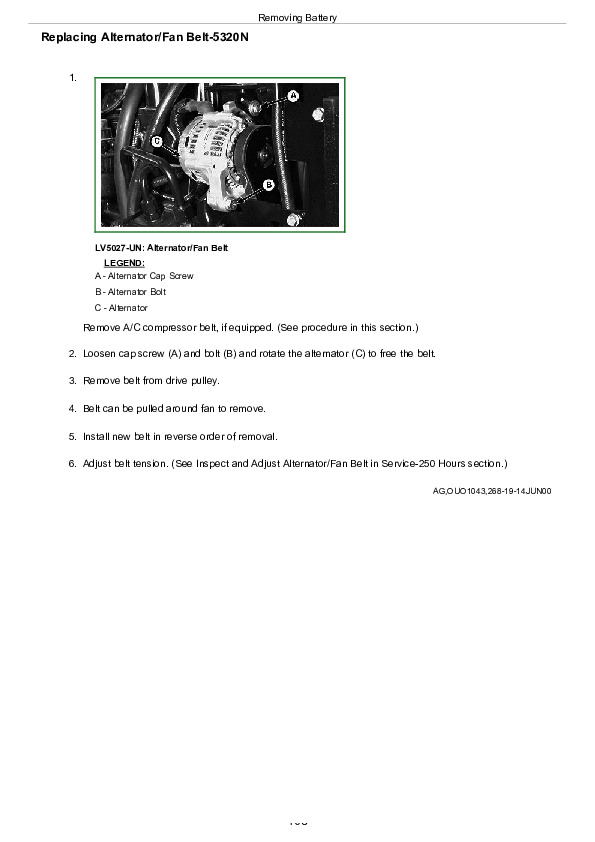
Replace Alternator/Regulator—4-Cylinder Engine
Replace Alternator/Regulator—5-Cylinder Engine
Group 10: Electrical System Components
Essential Tools
Other Material
Specifications
Replace Air Filter Restriction Switch
Replace Cold Start Advance Switch
Replace Coolant Temperature Sender—5325N Tractor
Replace Coolant Temperature Sender—5425N, 5525N, 5083EN, 5093EN, and 5101EN Tractors
Replace Engine Speed Sensor
Replace Engine Oil Pressure Switch
Replace Key Switch—Straddle Mount
Replace Key Switch—Cab Tractors
Replace Light Switch
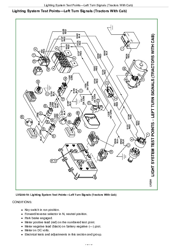
Replace Turn Signal Switch
Replace Instrument Panel
Program Instrument Cluster
Replace Rear PTO Switch—Straddle Mount
Replace Rear PTO Switch—Cab Tractors
Replace Rear PTO Switch—Electro-Hydraulic PTO
Replace Rockshaft Control Module—Electro-Hydraulic Hitch
Replace Load Depth Control—Electro-Hydraulic Hitch
Replace Fuel Level Sender—Straddle Mount
Replace Fuel Level Sender—Cab Tractors
Replace Front Wiper/Washer Control Switch
Replace Wiper Motor—Tractor with Cab
Replace Blower Control Switch
Replace A/C Temperature Control Switch
Replace Blower Motor Resistor
Replace Air Conditioning High/Low Pressure Switch
Replace Dome Light
Replace Door Switch
Replace Seat Switch—Cab Tractors
Replace Load Center Panel—Cab Tractors
Replace VEC Load Center—Straddle Mount
Replace Electro-Hydraulic Control Unit—Cab Tractors
Replace Hitch Solenoids—Cab Tractors
Replace Countershaft Speed Sensor—POWRREVERSER POWRREVERSER is a trademark of Deere & Company Tractors
Replace Wheel Speed Sensor
Replace Enable Pressure Sensor—POWRREVERSER POWRREVERSER is a trademark of Deere & Company Transmission
Replace Clutch Pedal Position Sensor—POWRREVERSER POWRREVERSER is a trademark of Deere & Company Transmission
Replace Clutch Disengage Switch—POWRREVERSER POWRREVERSER is a trademark of Deere & Company Transmission
Replace Rear PTO Sensor—POWRREVERSER POWRREVERSER is a trademark of Deere & Company Transmission—With Electro-Hydraulic PTO
Replace Hitch Draft Sensor—Electro-Hydraulic Hitch
Replace Hitch Position Sensor—Electro-Hydraulic Hitch
Replace Electro-Hydraulic Directional Reverser—POWRREVERSER POWRREVERSER is a trademark of Deere & Company Transmission
Replace Park Switch—POWRREVERSER POWRREVERSER is a trademark of Deere & Company Transmission
Replace Brake Pedal Switch—Electro-Hydraulic Tractors
Replace Hi/Lo Shifter Switch—POWRREVERSER POWRREVERSER is a trademark of Deere & Company Transmission
Replace External Raise/Lower Switch
Replace Clutch Enable Solenoid—POWRREVERSER POWRREVERSER is a trademark of Deere & Company Transmission
Replace Trans Forward Solenoid—POWRREVERSER POWRREVERSER is a trademark of Deere & Company Transmission
Replace Trans Reverse Solenoid—POWRREVERSER POWRREVERSER is a trademark of Deere & Company Transmission
Replace High Solenoid—POWRREVERSER POWRREVERSER is a trademark of Deere & Company Transmission—With Electro-Hydraulic Hi/Lo
Replace Rear PTO Solenoid—Electro-Hydraulic PTO
Replace MFWD Solenoid
Replace MFWD Switch
Replace Speakers
Group 15: Wiring Harness
Service Equipment and Tools
Service Parts Kits
Replace Connector Body—Blade Terminals
Replace WEATHER PACK WEATHER PACK is a trademark of Packard Electric. Connector
Install WEATHER PACK WEATHER PACK is a trademark of Packard Electric. Contact
Repair (Pull Type) METRI-PACK METRI-PACK is a trademark of Delphi Packard Electric Systems Connectors
Repair (Push Type) METRI-PACK Connectors
Replace Headlight Wiring Harness
Replace Fused Power Wiring Harness
Replace Front Wiring Harness—4-Cylinder
Replace Front Wiring Harness—5-Cylinder
Replace Rear Electrical Harness—Straddle Mount
Replace Rear Wiring Harness—Cab Tractors
Replace Console Wiring Harness—Cab Tractors
Replace Cab Roof and HVAC Wiring Harnesses
Section 50: Power Train Repair
Group 05: Clutch Housing
Essential Tools
Service Equipment and Tools
Other Material
Specifications
Separate Engine from Clutch Housing—Straddle Mount
Install Engine to Clutch Housing—Straddle Mount
Separate Engine from Clutch Housing—Cab Tractors
Install Engine to Clutch Housing—Cab Tractors
Inspect and Repair Clutch Pedal and Linkage—Straddle Mount (POWRREVERSER POWRREVERSER is a trademark of Deere & Company Transmissions)
Inspect and Repair Clutch Pedal and Linkage—Cab Tractors (POWRREVERSER POWRREVERSER is a trademark of Deere & Company Transmissions)
Group 10: Clutch Assembly—PowrReverser™ Transmission
Specifications
Remove and Install Clutch Assembly
Remove, Inspect, and Repair Transmission Pump
Group 11: POWRREVERSERPOWRREVERSER is a trademark of Deere & Company
Essential Tools
Service Equipment and Tools
Other Material
Specifications
Remove and Install POWRREVERSER POWRREVERSER is a trademark of Deere & Company Control Valve
Disassemble, Inspect, and Repair POWRREVERSER POWRREVERSER is a trademark of Deere & Company Control Valve
Remove and Install EH Hi/Lo Valve
Disassemble, Inspect, and Repair EH Hi/Lo Valve
Remove and Install POWRREVERSER POWRREVERSER is a trademark of Deere & Company —Transmissions Without EH Hi/Lo
Remove and Install POWRREVERSER POWRREVERSER is a trademark of Deere & Company —Transmissions With EH Hi/Lo
Disassemble, Inspect, and Repair Reverse Idle Gear—Transmissions Without EH Hi/Lo
Disassemble, Inspect, and Repair Reverse Idle Gear—Transmissions With EH Hi/Lo
Disassemble, Inspect, and Repair Clutch Gear—Transmissions Without EH Hi/Lo
Disassemble, Inspect, and Repair Connect Shaft—Transmissions With EH Hi/Lo
Disassemble, Inspect, and Repair Driven Shaft—Transmissions Without EH Hi/Lo
Disassemble, Inspect, and Repair Driven Shaft—Transmissions With EH Hi/Lo
Disassemble, Inspect, and Repair Hi/Lo Clutch Shaft—Transmissions With EH Hi/Lo
Disassemble, Inspect, and Repair POWRREVERSER POWRREVERSER is a trademark of Deere & Company —Transmissions Without EH Hi/Lo
Disassemble, Inspect, and Repair POWRREVERSER POWRREVERSER is a trademark of Deere & Company —Transmissions With EH Hi/Lo
Group 15: POWRREVERSERPOWRREVERSER is a trademark of Deere & Company Transmission
Essential Tools
Service Equipment and Tools
Other Material
Specifications
Separate Clutch Housing from Transmission—Straddle Mount
Install Clutch Housing to Transmission—Straddle Mount
Separate Clutch Housing from Transmission—Cab Tractors
Install Clutch Housing to Transmission—Cab Tractors
Remove Transmission
Disassemble and Inspect Transmission
Assemble Transmission
Install Transmission
Disassemble, Inspect, and Assemble Gearshift Shaft Assemblies
Disassemble, Inspect, and Assemble Transmission Bottom Shaft
Disassemble, Inspect, and Assemble Range Reduction Shaft
Disassemble, Inspect, and Assemble Top Shaft
Remove, Inspect, and Install MFWD and Range Gears
Group 20: Rear PTO Drive Shaft
Service Equipment and Tools
Other Material
Specifications
Inspect and Repair 540/540E PTO Shift Lever and Linkage
Remove and Install Rear 540/540E or 540/1000 Electro-Hydraulic PTO Shaft Assembly
Disassemble, Inspect, and Assemble Rear 540/540E Electro-Hydraulic and 540/1000 Electro-Hydraulic Pinion Shaft
Disassemble, Inspect, and Assemble Rear 540/540E Electro-Hydraulic PTO Output Shaft Assembly
Disassemble, Inspect, and Assemble Rear 540/1000 Electro-Hydraulic PTO Output Shaft Assembly
Remove, Inspect and Install Electro-Hydraulic PTO Valve
Group 25: Differential
Essential Tools
Service Equipment and Tools
Other Material
Specifications
Service Parts Kits
Remove and Install Differential Assembly
Disassemble, Inspect, and Assemble Differential Assembly
Remove and Inspect Differential Drive Shaft
Install Differential Drive Shaft
Remove, Inspect, and Install Differential Lock Assembly
Differential Cone Point Adjustment
Differential Backlash Adjustment
Group 30: Final Drives
Service Equipment and Tools
Other Material
Specifications
Remove and Install Final Drive Assembly
Remove and Inspect Planetary Drive Assembly
Install Planetary Drive Assembly
Remove, Inspect, and Install Axle Shaft Assembly
Group 35: Mechanical Front Wheel Drive
Essential Tools
Service Equipment and Tools
Other Material
Specifications
Remove and Install MFWD Drop Gearbox
Disassemble and Inspect MFWD Drop Gearbox
MFWD Drop Gearbox Cross Section
Assemble MFWD Drop Gearbox
Remove, Inspect, and Install MFWD Drive Shaft
Remove and Install MFWD Axle
Remove and Install MFWD Axle Pivot Pin and Pivot Bushings
Disassemble and Inspect MFWD Outer Drive
Assemble MFWD Outer Drive
Remove, Inspect, and Install MFWD Swivel Housing
Remove, Inspect, and Install MFWD Axle Shaft
Remove and Install MFWD Differential Carrier Assembly
Disassemble and Inspect MFWD Differential Carrier Assembly
Assemble MFWD Differential Carrier Assembly
Group 40: Creeper Assembly
Other Material
Specifications
Remove and Install Creeper Assembly
Disassemble, Inspect, and Assemble Creeper Assembly
Section 60: Steering and Brake Repair
Group 05: Steering Repair
Other Material
Specifications
Service Parts Kits
Remove and Install Straight Steering Column and Valve
Remove and Install Tilt/Telescoping Steering Column
Remove and Install Steering Valve—Tilt/Telescoping Steering Column
Disassemble and Inspect Steering Valve
Assemble Steering Valve
Remove and Install Steering Cylinder—2WD Axle
Disassemble, Inspect, and Assemble Steering Cylinder—2WD Axle
Disassemble, Inspect and Assemble Steering Cylinder—MFWD Axle
Remove, Inspect and Install Tie Rod Assembly—2WD Axle
Remove, Inspect and Install Tie Rod Assembly—MFWD Axle
Inspect and Replace Steering Hydraulic Lines—Straddle Mount
Inspect and Replace Steering Hydraulic Lines—Cab Tractors
Group 10: Brake Repair
Service Equipment and Tools
Other Material
Specifications
Remove and Install Brake Valve and Pedals
Disassemble and Inspect Brake Pedals and Valve
Brake Valve Cross Section
Assemble Brake Valve
Remove and Inspect Brakes
Install Brakes
Inspect and Replace Brake Hydraulic Lines
Section 70: Hydraulic Repair
Group 05: Hydraulic Pump and Filter
Service Parts Kit
Service Equipment and Tools
Specifications
Remove, Inspect, and Install Hydraulic Oil Pick-Up Screen
Remove and Install Hydraulic Pump—5-Cylinder Engine
Remove Hydraulic Pump External Components—5-Cylinder Engine
Disassemble and Inspect Hydraulic Pump—5-Cylinder Engine
Assemble Hydraulic Pump—5-Cylinder Engine
Install Hydraulic Pump External Components—5-Cylinder Engine
Remove and Install Hydraulic Pump—4-Cylinder Engine
Remove Hydraulic Pump External Components—4-Cylinder Engine
Disassemble and Inspect Hydraulic Pump—4-Cylinder Engine
Assemble Hydraulic Pump—4-Cylinder Engine
Install Hydraulic Pump External Components—4-Cylinder Engine
Remove and Install Hydraulic Oil Filter/Manifold
Inspect and Replace Hydraulic Supply/Return Lines—4-Cylinder Tractors (With SCV)
Inspect and Replace Hydraulic Supply/Return Lines—4-Cylinder Tractors (Without SCV)
Inspect and Replace Hydraulic Supply/Return Lines—5-Cylinder Tractors (With SCV)
Inspect and Replace Hydraulic Supply/Return Lines—5-Cylinder Tractors (Without SCV)
Group 06: Hydraulic Oil Cooler
Remove, Inspect, and Install Hydraulic Oil Cooler
Group 10: Rockshaft
Service Parts Kits
Other Material
Specifications
Inspect and Repair Draft Sensing Support Assembly
Rockshaft Control Valve (RCV) Repair
Rockshaft Control Valve Exploded View
Remove and Install Rockshaft Control Valve—Straddle Mount
Remove and Install Rockshaft Control Valve—Cab Tractors
Remove and Install Rockshaft Case—Straddle Mount
Remove and Install Rockshaft Case—Cab Tractors
Remove, Inspect, and Install Rockshaft Lift Arms
Remove, Inspect, and Install Rockshaft Piston and Cylinder
Group 15: Selective Control Valve
Service Parts Kits—Triple SCVs
Service Parts Kits—Dual SCVs
Other Material
Specifications
Inspect and Repair SCV Levers and Linkage
Remove and Install Dual or Triple Selective Control Valve (SCV)
Disassemble, Inspect, and Assemble Dual Selective Control Valve (SCV)
Triple Selective Control Valve (SCV) Cross-Sectional View
Disassemble, Inspect, and Assemble Triple Selective Control Valve (SCV)
Inspect and Replace Hydraulic Hoses—Control Valve (SCV)
Inspect and Replace Hydraulic Hoses—Control Valve (SCV) With Mid-Mount
Group 20: Hydraulic Mid-Mount Control Valve
Service Parts Kits
Other Material
Specifications
Inspect and Repair Joystick and Linkage
Remove and Install Mid-Mount Control Valve
Disassemble, Inspect, and Assemble Dual Mid-Mount Control Valve
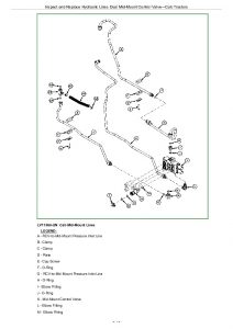
Inspect and Replace Hydraulic Lines Dual Mid-Mount Control Valve—Straddle Mount
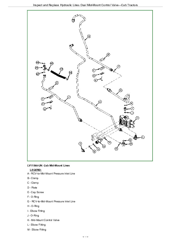
Inspect and Replace Hydraulic Lines Dual Mid-Mount Control Valve—Cab Tractors
Section 80: Miscellaneous Repair
Group 05: Front Axle—2WD
Specifications
Remove and Install Front Axle—2WD
Inspect and Replace Pivot Pin and Bushings—2WD Axle
Remove and Install Spindle Assembly—2WD Axle
Inspect and Replace Spindle Shaft Bushings—2WD Axle
Group 10: Wheels
Specifications
Inspect and Replace Front Wheel Bearings
Group 15: 3-Point Hitch
Specifications
Inspect and Repair Draft Links
Inspect and Repair Adjustable Lift Links
Inspect and Repair Center Link
Remove and Install Drawbar and Support
Group 20: Fenders
Specifications
Remove and Install Fenders—Straddle Mount
Group 25: Hood
Remove and Install Hood
Section 90: Operator Station Repair
Group 05: Seat and Support
Remove and Install Seat and Support
Group 06: Control Console and Panel
Remove and Install Right-Side Control Console—Straddle Mount
Remove and Install Left-Side Control Console—Straddle Mount
Remove and Install Right-Side Control Console—Cab Tractors
Remove and Install Left-Side Control Console—Cab Tractors
Remove and Install Cowl Cover
Group 10: ROLL-GARDROLL-GARD is a trademark of Deere & Company.
Specifications
Remove and Install ROLL-GARD ROLL-GARD is a trademark of Deere & Company
Group 15: Rear Bar
Specifications
Remove and Install Rear Bar—Straddle Mount
Group 20: Cab Components
Other Material
Essential Tools
Specifications
Remove Cab
Install Cab
Remove and Install Cab Outer Roof
Remove and Install Lower Front Windows
Remove and Install Rear Corner Cab Windows
Remove and Install Right Hand Cab Window
Remove and Install Rear Cab Window
Remove and Install Windshield
Remove and Install Cab Door
Remove, Inspect, and Install Cab Recirculating/Fresh Air Filter
Group 25: Air Conditioning System
Essential Tools
Service Equipment and Tools
Other Material
Service Parts Kits
Specifications
Recover/Recycle Air Conditioning Refrigerant
Replace Air Conditioning Receiver/Dryer
Remove, Inspect, and Install Air Conditioning Condenser
Remove, Inspect, and Install Air Conditioning Compressor
Test Volumetric Efficiency of Compressor
Test Compressor Shaft Seal Leakage
Disassemble and Assemble Compressor Clutch
Disassemble, Inspect, and Assemble Compressor
Check Compressor Clutch Hub Clearance
Inspect Compressor Manifold
Remove and Install Compressor Relief Valve
Remove Evaporator/Heater Core Housing
Install Evaporator/Heater Core Housing
Remove and Install Blower Motors
Remove Evaporator/Heater Core
Leak Test Evaporator/Heater Core
Install Evaporator/Heater Core
Service Expansion Valve
Expansion Valve Bench Test
Refrigerant Oil Information
Check Compressor Oil Charge
Determine Correct Refrigerant Oil Charge
Add Refrigerant Oil to System
System Information
Flush Air Conditioning System
Evacuate Air Conditioning System
Charge Air Conditioning System
Group 30: Heating System
Remove Heater Control Valve
Leak Test Heater Control Valve
Install Heater Control Valve
Section 99: Dealer Fabricated Tools
Group 05: Dealer Fabricated Tools
DFLV1A—Final Drive Turning Tool
DFRW20—Compressor Holding Fixture
DFT1162—Snap Ring Removal Tool


INSTANT DOWNLOAD


Posted on

John Deere Tractors 5320N, 5420N, 5520N Diagnostics & Repair Service Manual (TM1872)


INSTANT DOWNLOAD


Complete service Operator’s Manual for John Deere 5320N, 5420N and 5520N Tractors.

OMRE73927 – John Deere 5320N, 5420N and 5520N Tractors (North American) Operator’s Manual.pdf
Category: Operator’s Manual
Language: English
Published on 2003/11/24

ompfp17546
ompfp17546 – JDLink™ Modular Telematics Gateway 3G, Service ADVISOR™ Remote,and Ethernet Switch
Category: Operator’s Manual
Language: English

ompfp23380
ompfp23380 – AutoTrac™ Universal 300
Category: Operator’s Manual
Language: English

ompfp23600
ompfp23600 – JDLink™ R Modem – 4G
Category: Operator’s Manual
Language: English

PRODUCT DETAILS:
Total Pages: 576 pages
File Format: PDF (Internal Links, Bookmarked, Table of Contents, Searchable, Printable, high quality)
Language: English

TABLE OF CONTENTS
Section 05: Safety….16
  Recognize Safety Information….18
  Understand Signal Words….19
  Follow Safety Instructions….20
  Prevent Machine Runaway….21
  Use Seat Belt and Foldable ROPS Properly….22
  Operate Tractor Safely….24
  Locating Fusible Link….437
  Use Caution on Hillsides….153
  Shift to Low Gear on Hills….28
  Avoid Tipping….29
  Freeing a Mired Machine….30
  Work In Ventilated Area….385
  Park Tractor Safely….32
  Keep Riders Off Machine….33
  Handle Fuel Safely-Avoid Fires….286
  Prepare for Emergencies….35
  Do Not Use Starting Fluid….36
  Wear Protective Clothing….37
  Protect Against Noise….38
  Handle Chemical Products Safely….39
  Avoid Contact with Pesticides….40
  Stay Clear of Rotating Drivelines….208
  Use Safety Lights and Devices….276
  Use a Safety Chain….277
  Safely Transporting the Tractor….44
  Tow Loads Safely….45
  Keep ROPS Installed Properly….46
  Practice Safe Maintenance….47
  Service Tractor Safely….384
  Support Machine Properly….49
  Remove Paint Before Welding or Heating….50
  Avoid Heating Near Pressurized Fluid Lines….304
  Avoid High-Pressure Fluids….52
  Service Cooling System Safely….53
  Store Attachments Safely….54
  Prevent Acid Burns….55
  Service Tires Safely….241
  Dispose of Waste Properly….57
Section 10: Safety Signs….58
  Warning Labels….59
Section 15: Controls and Instruments….66
  Tractor Controls-Open Station….67
  Tractor Controls-Cab….69
  Instrument (Dash) Panel….71
  Overhead Control Panel-Cab….72
Section 20: Lights….74
  Light Switch Positions….75
  Using Headlights….76
  High Beam Indicator….77
  Using Tail Light-Open Station….78
  Using Rear Flood Light-Open Station….79
  Using Flood Lights-Cab….80
  Using Warning Lights-Open Station….82
  Using Warning Lights-Cab….84
  Using Turn Signals-Open Station….86
  Using Turn Signals-Cab….88
  Seven-Terminal Outlet-If Equipped….91
Section 25: Operator's Platform-Open Station….92
  Operating Foldable ROPS….93
  Using Seat Belt….99
  Selecting Seat Position….96
  Adjusting Ride Comfort….97
Section 30: Operator's Station-Cab….98
  Using Seat Belt….99
  Seat Adjustments….100
  Adjusting Steering Wheel Tilt….101
  Adjusting Blower Speed….102
  Controlling Temperature….103
  Operating Wiper(s)….104
  Accessory Electrical Outlet….105
  Optimizing A/C and Heater Performance….106
  Operating the Radio (Cab-If Equipped)….107
  Operating the Radio with Optional Cassette Tape Player (Cab-If Equipped)….108
  Operating the Radio with Optional Compact Disc Player (Cab-If Equipped)….109
  Operating the Optional Cassette Tape Player (Cab-If Equipped)….111
  Operating the Optional Compact Disc Player (Cab-If Equipped)….112
  Setting the Clock (Cab-If Equipped)….113
  Using Dome Light….114
  Storage Compartment….115
Section 35: Break-In Period….116
  Observe Engine Operation Closely….117
  Break-In Service….308
Section 40: Prestarting Checks….119
  Service Daily Before Start-Up….120
Section 45: Operating the Engine….122
  Before Starting the Engine….127
  Starting the Engine….127
  Check Instruments After Starting….129
  Oil Pressure Indicator….130
  Charging System Indicator….131
  Air Restriction Indicator….132
  Coolant Temperature Gauge….133
  Watch Fuel Level….134
  Changing Engine Speeds….135
  Warming Up the Engine….137
  Restart Stalled Engine….138
  Avoid Idling the Engine….139
  Observe Engine Work and Idle Speeds….140
  Working with Speed/Hour Meter….141
  Stopping the Engine….142
  Cold Weather Starting Procedure Using Intake Air Heater System-If Equipped….143
  Using Booster Battery….145
Section 50: Driving the Tractor….146
  Operator Training Required….147
  Avoid Contact With Pesticides….148
  Driving on Public Roads….149
  Use Caution on Hillsides….153
  Observe Maximum Travel Speeds….154
  Selecting a Gear….155
  Shifting Transmission….156
  Using Brakes….158
  Using Differential Lock….159
  Operating Mechanical Front Wheel Drive-If Equipped….160
  Stopping The Tractor….161
Section 55: Rockshaft and 3-Point Hitch….165
  Match Tractor Power to Implement….166
  3-Point Hitch Components….167
  Rockshaft Control Levers….168
  Using Rockshaft Position Control….170
  Setting Position Control Lever Stop….172
  Using Draft Control….173
  Adjusting Rockshaft Rate-of-Drop….175
  Preparing Implement….176
  Converting Category II Hitch to Category IN or Category I….178
  Positioning Draft Link Ends….179
  Positioning Center Link….180
  Attaching Implements to 3-Point Hitch….181
  Adjusting Sway Blocks….183
  Leveling the Hitch….184
  Adjusting Rockshaft Control Lever Friction-Open Station….186
  Adjusting Rockshaft Control Lever Friction-Cab….188
  Warming Hydraulic System Oil….190
Section 60: Remote Hydraulic Cylinders….192
  Use Correct Hose Tips….193
  SCV Control Lever and Coupler Identification….194
  Installing Remote Outlet Oil Manifolds-Optional….195
  Connecting Cylinder Hoses….196
  Operating SCV Controls….199
  Adjusting Cylinder Stop….201
  Power Beyond Valve Operation-If Equipped….202
  Disconnecting Cylinder Hoses….203
Section 65: Drawbar and PTO….204
  Observe Drawbar Load Limitations….205
  Selecting Drawbar Position….206
  Adjusting Drawbar Length….207
  Stay Clear of Rotating Drivelines….208
  Attaching PTO-Driven Implement….209
  Selecting Correct PTO Speeds….210
  Operating Tractor PTO….211
  Adjusting PTO Clutch Operating Rod-Open Station….344
  Adjusting PTO Clutch Operating Rod-Cab….347
Section 70: Ballast….220
  Planning for Maximum Productivity….221
  Selecting Ballast Carefully….222
  Matching Ballast to Load Work….223
  Checking for Correct Ballast….224
  Measuring Wheel Slip-Manually….225
  Ballast Limitations….226
  Ballasting Front End for Transport….227
  Ballasting Two-Wheel Drive Tractors….228
  Ballasting MFWD-Equipped Tractors….229
  Determining Maximum Rear Ballast….230
  Determining Maximum Front Ballast….231
  Using Cast Iron Weights….233
  Installing Rear Cast Iron Weights….234
  Using Liquid Weight….235
  Using Implement Codes….238
Section 75: Wheels, Tires and Treads….240
  Service Tires Safely….241
  Check Implement-to-Tire Clearance….242
  Check Tire Inflation Pressure….243
  Tire Inflation Pressure Chart….244
  Selecting Front Tire Rolling Direction….246
  Tighten Wheel/Axle Hardware Correctly….247
  Tighten Bolts-Adjustable Front Axle….248
  Tighten Bolts-MFWD Axle….249
  Tighten Bolts-Rear Axle….250
  Observe Rear Wheel Tread Width Limitations….251
  Tread Settings-Two-Position Rear Wheels-Early Model Tractor….252
  Tread Settings-Two-Position Rear Wheels-Late Model Tractor….253
  Tread Settings-Multi-Position Rear Wheels-Early Model Tractor….254
  Tread Settings-Multi-Position Rear Wheels-Late Model Tractor….256
  Tread Settings-Two-Position MFWD Wheels-Early Model Tractor….258
  Tread Settings-Two-Position MFWD Wheels-Late Model Tractor….259
  Tread Settings-Adjustable Front Axle-Early Model Tractor….260
  Tread Settings-Adjustable Front Axle-Late Model Tractor….261
  Adjust Front Axle Tread Width….263
  Checking Toe-In-Two-Wheel Drive Tractor….264
  Adjusting Toe-In-Two-Wheel Drive Tractor….265
  Checking Toe-In-MFWD Tractor….266
  Adjusting Toe-In-MFWD Tractor….267
  Set MFWD Steering Stops-MFWD Axle….268
  Use Correct Tire Combinations….269
  Tire Compatibility Chart-Early Model Tractor….270
  Tire Compatibility Chart-Late Model Tractor….273
Section 80: Transporting….275
  Use Safety Lights and Devices….276
  Use a Safety Chain….277
  Driving Tractor on Roads….278
  Transport on Carrier….283
  Towing Tractor….284
Section 85: Fuels, Lubricants, and Coolant….285
  Handle Fuel Safely-Avoid Fires….286
  Handle Fluids Safely-Avoid Fires….287
  Fuel Storage….288
  Cold Weather Operation….289
  Diesel Fuel….290
  Fill Fuel Tank….292
  Alternative and Synthetic Lubricants….293
  Lubricant Storage….294
  Diesel Engine Oil….295
  Oil Filters….296
  Diesel Engine Coolant….297
  Liquid Coolant Conditioner….298
  Anti-Chatter Transmission/Hydraulic Oil….299
  Use Correct Hydraulic-Transmission Filter Element….300
  Gear Oil….301
  Grease….302
Section 90: Lubrication and Maintenance….303
  Avoid Heating Near Pressurized Fluid Lines….304
  Clean Vehicle of Hazardous Pesticides….386
  Observe Service Intervals….309
  Use Correct Lubricant….307
  Break-In Service….308
  Service Intervals….309
Section 95: Service-10 Hours….311
  Check Engine Oil Level….312
  Check Coolant Level….313
  Drain Water and Sediment from Fuel Tank and Fuel Filter….314
  Lubricate as Necessary….316
Section 100: Service-50 Hours….317
  Check Transmission-Hydraulic System Oil Level….318
  Check MFWD Axle Oil Level….319
  Clean and Check Battery….320
  Inspect All Tires….321
  Lubricate Front Axle Pivot Pin….322
  Lubricate Steering Cylinder Ends and Steering Spindles-Adjustable Front Axle….323
  Lubricate Steering King Pins-MFWD….324
  Inspect Tractor for Loose Hardware….325
Section 105: Service-100 Hours….326
  Change Engine Oil and Filter….369
  Replace Transmission-Hydraulic Filter….329
Section 110: Service-250 Hours….330
  Service Air Cleaner….377
  Inspect and Adjust Alternator/Fan Belt-5320N….332
  Inspect and Adjust A/C Compressor Belt -Cab (5320N)….333
  Inspect and Replace A/C Compressor Belt-Cab (5420N and 5520N)….334
  Lubricate 3-Point Hitch….337
  Check Neutral Start System….338
  Check and Adjust Clutch Pedal Free Play-Open Station….339
  Check and Adjust Clutch Pedal Free Play-Cab….340
  Clean Cab Air Filters….342
  Adjusting PTO Clutch Operating Rod-Open Station….344
  Adjusting PTO Clutch Operating Rod-Cab….347
Section 115: Service-500 Hours….350
  Replace Fuel Filter….351
Section 120: Service-600 Hours….352
  Change Oil in MFWD Axle-If Equipped….353
  Clean Engine Crankcase Vent Tube….355
  Pack Front Wheel Bearings-Adjustable Front Axle….356
  Check Hoses and Hose Clamps for Tightness….357
  Lubricate Rear Axle Bearings….360
  Check Engine Idle Speeds….361
  Check Front Axle Pivot Pin….362
  Check and Adjust Engine Valve Clearance….363
Section 125: Service-1200 Hours….364
  Change Transmission-Hydraulic Oil and Filter….365
  Clean Transmission-Hydraulic Pickup Screen….366
Section 130: Service-Annually….368
  Change Engine Oil and Filter….369
  Replace Air Cleaner Elements….370
  Inspecting Seat Belt….371
Section 135: Service-2 Years/2000 Hours….372
  Flush Cooling System….416
Section 140: Service-As Required….376
  Service Air Cleaner….377
  Adjust Throttle Friction….378
  Adjust 540E PTO Throttle Limiter-Open Station….379
  Adjust 540E PTO Throttle Limiter-Cab….380
Section 145: Service….382
  Service Tractor Safely….384
  Work In Ventilated Area….385
  Clean Vehicle of Hazardous Pesticides….386
  Engine Break-In Oil….387
  Using High-Pressure Washers….388
  Additional Service Information….389
  Opening Hood….390
  Removing Hood….391
  Removing Side Screens….392
  Air Intake System Components….393
  Service Air Cleaner at Regular Intervals….394
  Checking Air Intake System….395
  Removing Air Cleaner Elements….397
  Inspecting Element….399
  Cleaning Primary Element….400
  Washing Primary Element….401
  Storing Element….402
  Replacing Alternator/Fan Belt-5320N….403
  Replacing Fan/Alternator/AC Compressor Belt-5420N and 5520N….404
  Replacing A/C Compressor Belt (Cab-5320N)….406
  Fuel System Components….407
  Bleeding Fuel System….409
  Do Not Modify Fuel System….411
  Engine Cooling System Components….412
  Cleaning Grille, Screens, Radiator, Oil Cooler and Air Conditioner Condenser….414
  Flush Cooling System….416
  Replacing Thermostat….417
  Winterize Cooling System….420
  Prevent Battery Explosions….421
  Observe Electrical Service Precautions….422
  Battery Access-Open Station Machines….423
  Battery Access-Cab Machines….424
  Removing Battery….425
  Servicing Battery….426
  Battery Replacement Specifications….429
  Charging Battery….430
  Checking Battery Condition….432
  Connecting Starter Wiring….433
  Connecting Alternator Wiring….434
  Servicing Air Conditioner….435
  Locating Fusible Link….437
  Locating Fuses….438
  Fuse Size and Function-Early Model Tractors Without Cab….439
  Fuse Size and Function-Later Model Tractors Without Cab….440
  Fuse Size and Function-All Cab Tractors….441
  Fuse Size and Function-Cab….442
  Aiming Headlights….443
  Adjusting Headlights….444
  Replace Headlight Bulb….445
  Replace Warning Light Bulb-Cab….447
  Replace Warning Light Bulb-Open Station….448
  Replace Tail/Turn Signal Light Bulb-Cab….449
  Replace Tail Light Bulb-Open Station….450
  Replace Rear Flood Light Bulb-Open Station….451
  Replace Flood Light Bulb-Cab….452
  Replace Dome Light Bulb-Cab….453
  Checking and Adjusting Park Brake Lever….454
  Checking Tires….456
  Tubeless Tire Repair….457
  Keep ROPS Installed Properly-Open Station….458
  Keep Cab Protection System Installed Properly….460
Section 150: Troubleshooting….462
  Engine Troubleshooting….463
  Transmission Troubleshooting….468
  Hydraulic System Troubleshooting….469
  Brakes Troubleshooting….470
  Rockshaft and Quick-Coupler 3-Point Hitch Troubleshooting….471
  Remote Hydraulic Cylinders Troubleshooting….473
  Electrical System Troubleshooting….474
  Heater and A/C System Troubleshooting-Cab….476
  Wipers, Flood Lights, Dome Light and Radio Troubleshooting-Cab….480
Section 155: Storage….481
  Storing Tractor….482
  Removing Tractor From Storage….486
Section 160: Specifications….488
  Machine Specifications….489
  Drain and Refill Capacities….493
  5320N Machine Dimensions….494
  5420N Machine Dimensions….496
  5520N Machine Dimensions….498
  Permissible Load Specifications….500
  SyncReverser™ Transmission Ground Speed Estimates….501
  Creeper Transmissions Ground Speed Estimates….502
  Correction Factors for Other Tire Sizes….503
  Metric Bolt and Cap Screw Torque Values….504
  Unified Inch Bolt and Cap Screw Torque Values….506
  Emissions Control System Certification Label….508
  U.S. Emissions Control Warranty Statement (United States Only)….509
  Limited Battery Warranty….510
Section 165: Identification Numbers….512
  Identification Plates….513
  Record Tractor Serial Number….514
  Record Adjustable Front Axle (2-WD) Serial Number….515
  Record Mechanical Front Wheel Drive (MFWD) Serial Number….516
  Record Engine Serial Number….517
  Record Transmission Serial Number….518
Section 170: Lubrication and Maintenance Record Charts….519
  50, 250, 500 Hour Service Chart….520
  600 Hour Service Chart….522
  1000, 1200 Hour Service Chart….524
  Annual Service Chart….526
  2000 Hour Service Chart….527
  As Required Service Chart….528
Section 175: Crime Prevention Tips….529
  Help Prevent Crime….530
  Record Ag Identification Numbers….531
  Keep Proof of Ownership….532
  Park Indoors Out of Sight….533
  When Parking Outdoors….534
  Reduce Vandalism….535
  Report Thefts Immediately….536
Section SLIT: John Deere Service Literature Available….537
  Parts Catalog….538
  Operator's Manual….539
  Fundamentals of Service Manuals….540
  Technical and Service Manuals….541
  Know-How Booklets….542
  Common Questions Booklet….543
Section IBC: John Deere Service Keeps You on the Job….544
  John Deere Quality….545

John Deere 5320N, 5420N and 5520N Tractors (North American) Operator’s Manual (OMRE73927)


INSTANT DOWNLOAD


Posted on

John Deere Tractors 5320N, 5420N, 5520N Diagnostics & Repair Service Manual (TM1872)


INSTANT DOWNLOAD


Complete All Inclusive Technical Manual with electrical wiring diagrams for John Deere Tractors 5320N, 5420N, 5520N, with all the shop information to maintain, diagnose, repair, and service like professional mechanics (Diagnosis, Operation, Tests, Repair, Service, Troubleshooting).

John Deere USA Tractors 5320N, 5420N, 5520N workshop diagnosis repair service manual includes:
* Numbered table of contents easy to use so that you can find the information you need fast.
* Detailed sub-steps expand on repair procedure information
* Numbered instructions guide you through every repair procedure step by step.
* Troubleshooting and electrical service procedures are combined with detailed wiring diagrams for ease of use.
* Notes, cautions and warnings throughout each chapter pinpoint critical information.
* Bold figure number help you quickly match illustrations with instructions.
* Detailed illustrations, drawings and photos guide you through every procedure.
* Enlarged inset helps you identify and examine parts in detail.

TM1872 – John Deere 5320N, 5420N and 5520N Tractors Diagnostic and Repair Technical Manual.pdf
Category: Technical Manual
Language: English
Published on 2021/11/12

tm9111 French – Manuel technique de diagnostic et de remise en état des tracteurs 5320N, 5420N et 5520N
Published on 2021/12/04

tm114519 – JDLink™ 2G / 3G MTG Technical Manual
Category: Technical Manual
Language: English
Published on 2019/12/14

tm117919 – StarFire™ 3000 Technical Manual
Category: Technical Manual
Language: English
Published on 2019/03/01

tm126119 – AutoTrac™ Universal Technical Manual
Category: Technical Manual
Language: English
Published on 2021/07/03

tm143019 – JDLink™ Modem – 4G Technical Manual
Category: Technical Manual
Language: English
Published on 2023/04/19

tm150619 – AutoTrac™ Universal 300 Technical Manual
Category: Technical Manual
Language: English
Published on 2022/07/14

tm155719 – JDLink™ R Modem – 4G Technical Manual
Category: Technical Manual
Language: English
Published on 2023/04/14

ctm104
ctm104 – 4.5L AND 6.8L DIESEL ENGINES (BASE ENGINE) -: (WORLDWIDE EDITION)
Category: CTM
Language: English
Published on 2023/02/09

ctm125
ctm125 – PowerTech™ 2.9 LDiesel Engines -: (Worldwide Edition)
Category: CTM
Language: English
Published on 2021/01/08

ctm207
ctm207 – PowerTech™ 4.5L and 6.8L Diesel EnginesMechanical Fuel Systems -: (Worldwide Edition)
Category: CTM
Language: English
Published on 2022/10/27

PRODUCT DETAILS:
Total Pages: 2,212 pages
File Format: PDF (bookmarked, ToC, Searchable, Printable, high quality)
Language: English

MAIN SECTION
Foreword
   General Information
      Safety
      General Specifications
      Fuel and Lubricants
      Serial Number Locations
      Features and Accessories
   Engine Repair
      Engine
      Cooling System
   Fuel and Air Repair
      Fuel System
      Air Intake System
      Speed Control Linkage
   Electrical Repair
      Battery, Starter, and Alternator
      Electrical System Components
      Wiring Harness
   Power Train Repair
      Clutch Housing
      Clutch Assembly
      Synchronized Reverser
      Transmission
      Rear PTO Drive Shaft
      Differential
      Final Drives
      Mechanical Front Wheel Drive
      Creeper Assembly
   Steering and Brake Repair
      Steering Repair
      Brake Repair
   Hydraulic Repair
      Hydraulic Pump and Filter
      Hydraulic Oil Cooler
      Rockshaft
      Selective Control Valve (SCV)
      Hydraulic Power Beyond
   Miscellaneous Repair
      Front Axle-2WD
      Wheels
      Fenders
      3-Point Hitch
   Operator Station Repair
      Seat and Support
      ROLL-GARD™
      Rear Bar
      Cab Components
      Air Conditioning System
      Heating System
   Operational Checkout Procedures
      Operational Checkout Procedures
   Engine Operation, Tests and Adjustments
      Component Location
      Theory of Operation
      Diagnosis, Tests and Adjustments
   Fuel/Air Operation, Tests and Adjustments
      Component Location
      Theory of Operation
      Diagnosis, Tests and Adjustments
   Electrical System Operation, Tests & Adjust
      Component Location
      Theory of Operation
      Diagnosis, Test and Adjust
      Wiring Schematics
   Power Train Operation, Tests & Adjustments
      Component Location
      Theory of Operation
      Diagnosis, Tests and Adjustments
   Steering and Brake Operation, Test & Adjust
      Component Location
      Theory of Operation
      Diagnosis, Tests and Adjustments
   Hydraulic System Operation, Tests, and Adjustments
      Component Location
      Theory of Operation
      Diagnosis
      Hydraulic Tests
      Adjustments
      Hydraulic Schematics
   Operator Station
      Component Location
      Theory of Operation
      Diagnosis, Tests, and Adjustments
   Dealer Fabricated Tools

tm1872 – 5320N, 5420N and 5520N Tractors Diagnostic and Repair Technical Manual

Table of Contents

Foreword

Section 10: General Information

Group 05: Safety

Recognize Safety Information

Understand Signal Words

Follow Safety Instructions

Handle Fluids Safely—Avoid Fires

Prevent Battery Explosions

Prepare for Emergencies

Prevent Acid Burns

Service Cooling System Safely

Handle Chemical Products Safely

Avoid High-Pressure Fluids

Park Machine Safely

Support Machine Properly

Wear Protective Clothing

Work in Clean Area

Service Machines Safely

Work In Ventilated Area

Illuminate Work Area Safely

Replace Safety Signs

Use Proper Lifting Equipment

Keep ROPS Installed Properly

Service Tires Safely

Avoid Harmful Asbestos Dust

Avoid Heating Near Pressurized Fluid Lines

Remove Paint Before Welding or Heating

Use Proper Tools

Dispose of Waste Properly

Live With Safety

Group 10: General Specifications

Machine Specifications

SyncReverser™ Transmission Ground Speed Estimates

Creeper Transmission Ground Speed Estimates

Correction Factors for Other Tire Sizes

Service Recommendations for O-Ring Boss Fittings

Service Recommendations For Flat Face O-Ring Seal Fittings

Metric Cap Screw Torque Values—Grade 7

Metric Bolt and Screw Torque Values

Unified Inch Bolt and Screw Torque Values

Group 20: Fuel and Lubricants

Diesel Fuel Specifications

Storing Fuel

Do Not Use Galvanized Containers

Fill Fuel Tank

Diesel Engine Oil — Non-Emissions Certified and Certified Tier 1 and Stage I

Diesel Engine Coolant (engine with wet sleeve cylinder liners)

Liquid Coolant Conditioner

Transmission and Hydraulic Oil

MFWD Gear Oil

Grease

Alternative and Synthetic Lubricants

Lubricant Storage

Group 25: Serial Number Locations

Serial Numbers

Product Identification Number Location

Engine Serial Number Location

Fuel Injection Pump Serial Number Location

Alternator Serial Number Location

Power Steering Valve Serial Number Location

Starter Serial Number Location

Transmission Serial Number Location

Front Axle (2WD) Serial Number Location

Mechanical Front Wheel Drive (MFWD) Serial Number Location

Air Conditioning Compressor Serial Number Location

Group 30: Features and Accessories

Features and Accessories

Standard Features

Factory Installed Optional Equipment

Field Installed Optional Kits and Accessories

Section 20: Engine Repair

Group 05: Engine

Specifications

Service Equipment and Tools

John Deere Engine Repair—Use CTM104, CTM125 or CTM207

Remove Engine—Tractors Without Cab

Install Engine—Tractors Without Cab

Remove Engine—Tractors With Cab

Install Engine—Tractors With Cab

Group 10: Cooling System

Specifications

Engine Water Pump Repair—Use CTM104 or CTM125

Remove and Inspect Radiator

Install Radiator

Replace Thermostat

Inspect and Replace Belt Tensioner

Section 30: Fuel and Air Repair

Group 05: Fuel System

Specifications

Injection Pump, Nozzle and Governor Repair—Use CTM207 or CTM125

Remove, Inspect, and Install Fuel Tank—Tractors Without Cab

Remove, Inspect, and Install Fuel Tanks—Tractors With Cab

Replace Fuel Filter

Remove and Install Fuel Filter/Primer Pump Assembly

Group 10: Air Intake System

Specifications

Turbocharger Repair—Use CTM104 or CTM125

Remove, Inspect, and Install Air Cleaner Elements—5320N

Remove, Inspect, and Install Air Cleaner Elements—5420N and 5520N

Remove Turbocharger—5320N

Install Turbocharger—5320N

Remove Turbocharger—5520N

Install Turbocharger—5520N

Turbocharger Break-In

Group 15: Speed Control Linkage

Inspect and Repair Speed Control Linkage—Tractors Without Cab

Inspect and Repair Speed Control Linkage—Tractors With Cab

Section 40: Electrical Repair

Group 05: Battery, Starter, and Alternator

Starter Repair—Use CTM77

Remove and Install Battery—Tractor Without Cab

Remove and Install Battery—Tractor With Cab

Remove and Install Starter—5320N

Remove and Install Starter—5420N and 5520N

Replace Alternator/Regulator—40 Amp Without Cab

Replace Alternator/Regulator—60 and 65 Amp With Cab

Group 10: Electrical System Components

Other Material

Replace Air Filter Restriction Switch—5320N

Replace Air Filter Restriction Switch—5420N and 5520N

Replace Coolant Temperature Sender—5320N

Replace Coolant Temperature Sender—5420N and 5520N

Replace Engine Speed Sensor

Replace Engine Oil Pressure Switch

Replace Air Intake Heater (Optional Equipment)

Replace Air Intake Heater Relay (Optional Equipment)

Replace Key Switch

Replace Light Switch (S.N. —438002)

Replace Light Switch (S.N. 438003— )

Replace Turn Signal Controller

Replace Instrument Panel (S.N. —438002)

Replace Instrument Panel (S.N. 438003— )

Replace Rear PTO Switch—Tractor Without Cab

Replace Rear PTO Switch—Tractor With Cab

Replace PTO Seat Switch—Tractor Without Cab

Replace Neutral Start Switch—Tractor Without Cab

Replace Neutral Start Switch—Tractor With Cab

Replace Fuel Level Sender—Tractors Without Cab

Replace Fuel Level Sender—Tractors With Cab

Replace Park Brake Switch—Tractor Without Cab

Replace Park Brake Switch—Tractor With Cab

Replace Radio (Optional Equipment)

Replace Speakers

Replace Antenna (Optional Equipment)

Replace Blower Control Switch

Replace Air Conditioning Temperature Control Switch

Replace Front Wiper/Washer Control Switch

Replace Dome Light

Replace Dome Light Switch

Replace Convenience Outlet

Replace Cab Plug-In Relays

Replace Front Wiper Motor—Tractor With Cab

Group 15: Wiring Harness

Special or Essential Tools

Service Parts Kits

Remove Connector Body from Blade Terminals

Replace WEATHER PACK WEATHER PACK is a trademark of Packard Electric Connector

Install WEATHER PACK WEATHER PACK is a trademark of Packard Electric Contact

Replace Front Wiring Harness—3-Cylinder

Replace Front Wiring Harness—4-Cylinder

Replace Rear Wiring Harness—Tractors Without Cab (S.N. —438002)

Replace Rear Wiring Harness—Tractors Without Cab (S.N. 438003— )

Replace Rear Wiring Harness—Tractors With Cab

Replace Cab Main Wiring Harness

Replace Cab Controls Wiring Harness

Section 50: Power Train Repair

Group 05: Clutch Housing

Service Equipment and Tools

Other Material

Specifications

Service Parts Kits

Separate Engine from Clutch Housing—Tractors Without Cab

Install Engine to Clutch Housing—Tractors Without Cab

Separate Engine from Clutch Housing—Tractors With Cab

Install Engine to Clutch Housing—Tractors With Cab

Inspect and Repair Clutch Pedal and Linkage—Tractors Without Cab

Inspect and Repair Clutch Pedal and Linkage—Tractors With Cab

Group 10: Clutch Assembly

Essential Tools

Service Equipment and Tools

Other Material

Specifications

Remove and Install Clutch Assembly

Disassemble and Inspect Clutch Assembly

Assemble Clutch Assembly

Traction Clutch Finger Adjustment

PTO Clutch Finger Adjustment

Remove and Inspect Clutch Release Mechanism and Shafts

Install Clutch Release Mechanism and Shafts

Install Clutch Release Mechanism and Shafts

Group 15: Synchronized Reverser

Service Equipment and Tools

Specifications

Inspect and Repair F-N-R Selector Lever and Linkage

Inspect and Repair Synchronized Reverser

Group 20: Transmission

Service Equipment and Tools

Other Material

Specifications

Inspect and Repair Park Brake Lever

Separate Clutch Housing from Transmission—Tractors Without Cab

Install Clutch Housing to Transmission—Tractors Without Cab

Separate Clutch Housing from Transmission—Tractors With Cab

Install Clutch Housing to Transmission—Tractors With Cab

Remove, Inspect, and Repair Gear Shift Lever—Tractors Without Cab

Remove, Inspect, and Repair Gear Shift Lever—Tractors With Cab

Remove, Inspect, and Repair Range Shift Lever—Tractors Without Cab

Remove, Inspect, and Repair Range Shift Lever—Tractors With Cab

Remove Transmission—Tractors Without Cab

Remove Transmission—Tractors With Cab

Disassemble and Inspect Transmission

Assemble and Install Transmission—Tractors Without Cab

Assemble and Install Transmission—Tractors With Cab

Disassemble, Inspect, and Assemble Shift Shaft Assemblies

Disassemble, Inspect, and Assemble Transmission Top Shaft

Disassemble, Inspect, and Assemble Range Reduction Shaft

Disassemble, Inspect, and Assemble Driven Shaft

Remove, Inspect, and Install MFWD and Range Gears

Remove, Inspect, and Repair Park Brake

Group 25: Rear PTO Drive Shaft

Service Equipment and Tools

Other Material

Specifications

Inspect and Repair Rear PTO Lever and Linkage-Tractors Without Cab

Inspect and Repair Rear PTO Lever and Linkage-Tractors Without Cab

Inspect and Repair Rear PTO Lever and Linkage—Tractors With Cab

Inspect and Repair Rear PTO Lever and Linkage (540/540E)—Tractors Without Cab

Inspect and Repair Rear PTO Lever and Linkage (540/540E)—Tractors Without Cab

Inspect and Repair Rear PTO Lever and Linkage (540/540E)—Tractors With Cab

Inspect and Repair Rear PTO Lever and Linkage (540/540E)—Tractors With Cab

Remove and Install Rear PTO Drive Shaft Assembly

Disassemble, Inspect, and Assemble Rear PTO Drive Shaft Assembly

Group 30: Differential

Essential Tools

Service Equipment and Tools

Other Material

Specifications

Service Parts Kit

Remove and Install Differential Assembly

Disassemble, Inspect, and Assemble Differential Assembly

Remove and Inspect Differential Drive Shaft

Install Differential Drive Shaft

Remove, Inspect, and Install Differential Lock Assembly

Differential Cone Point Adjustment

Differential Backlash Adjustment

Group 35: Final Drives

Essential Tools

Service Equipment and Tools

Other Material

Specifications

Remove and Install Final Drive Assembly

Remove and Inspect Planetary Drive Assembly

Install Planetary Drive Assembly

Remove, Inspect, and Install Axle Shaft Assembly

Group 40: Mechanical Front Wheel Drive

Essential Tools

Service Equipment and Tools

Other Material

Specifications

Inspect and Repair MFWD Lever and Linkage—Tractors Without Cab

Inspect and Repair MFWD Lever and Linkage—Tractors With Cab

Remove and Install MFWD Drop Gearbox

Disassemble and Inspect MFWD Drop Gearbox

MFWD Drop Gearbox Cross Section

Assemble MFWD Drop Gearbox

Remove, Inspect, and Install MFWD Drive Shaft

Remove and Install MFWD Axle

Remove and Install MFWD Axle Pivot Pin and Pivot Bushings

Disassemble and Inspect MFWD Outer Drive

Assemble MFWD Outer Drive

Remove, Inspect, and Install MFWD Swivel Housing

Remove, Inspect, and Install MFWD Axle Shaft

Remove and Install MFWD Differential Carrier Assembly

Disassemble and Inspect MFWD Differential Carrier Assembly

Assemble MFWD Differential Carrier Assembly

Group 45: Creeper Assembly

Other Material

Specifications

Remove and Install Creeper Assembly

Disassemble, Inspect, and Assemble Creeper Assembly

Section 60: Steering and Brake Repair

Group 05: Steering Repair

Other Material

Specifications

Service Parts Kits

Remove and Install Steering Column and Valve

Disassemble and Inspect Steering Valve

Assemble Steering Valve

Remove and Install Steering Cylinder—2WD Axle

Disassemble, Inspect, and Assemble Steering Cylinder—2WD Axle

Disassemble, Inspect and Assemble Steering Cylinder—MFWD Axle

Remove, Inspect and Install Tie Rod Assembly—2WD Axle

Remove, Inspect and Install Tie Rod Assembly—MFWD Axle

Inspect and Replace Steering Hydraulic Lines—3-Cylinder Tractors Without Cab

Inspect and Replace Steering Hydraulic Lines—4-Cylinder Tractors Without Cab

Inspect and Replace Steering Hydraulic Lines—3- And 4-Cylinder Tractors With Cab

Group 10: Brake Repair

Service Equipment and Tools

Other Material

Specifications

Remove and Install Brake Valve (S.N. —438002)

Disassemble and Inspect Brake Pedals and Valve (S.N. —438002)

Brake Valve Cross Section (S.N. —438002)

Assemble Brake Valve (S.N. —438002)

Remove and Install Brake Valve (S.N. 438003— )

Disassemble and Inspect Brake Pedals and Valve (S.N. 438003— )

Brake Valve Cross Section (S.N. 438003— )

Assemble Brake Valve (S.N. 438003— )

Remove and Inspect Brakes

Install Brakes

Inspect and Replace Brake Hydraulic Lines

Inspect and Replace Brake Hydraulic Lines

Section 70: Hydraulic Repair

Group 05: Hydraulic Pump and Filter

Service Equipment and Tools

Specifications

Service Parts Kits

Remove, Inspect, and Install Hydraulic Oil Pick-Up Screen

Remove and Install Hydraulic Pump—5320N

Remove Hydraulic Pump External Components—5320N

Disassemble and Inspect Hydraulic Pump—5320N

Assemble Hydraulic Pump—5320N

Install Hydraulic Pump External Components—5320N

Remove and Install Hydraulic Pump—5420N and 5520N

Remove Large Capacity Hydraulic Pump External Components—5420N and 5520N

Disassemble and Inspect Large Capacity Hydraulic Pump—5420N and 5520N

Assemble Large Capacity Hydraulic Pump—5420N and 5520N

Install Large Capacity Hydraulic Pump External Components—5420N and 5520N

Remove and Install Hydraulic Oil Filter/Manifold

Inspect and Replace Hydraulic Supply/Return Lines—Tractors Without Cab

Inspect and Replace Hydraulic Supply/Return Lines—Tractors With Cab

Group 06: Hydraulic Oil Cooler

Remove, Inspect, and Install Hydraulic Oil Cooler

Group 10: Rockshaft

Service Equipment and Tools

Other Material

Specifications

Service Parts Kits

Inspect and Repair Rockshaft Control Lever Assembly—Tractors Without Cab

Inspect and Repair Rockshaft Control Lever Assembly—Tractors With Cab

Inspect and Repair Rockshaft Control Linkage

Inspect and Repair Draft Sensing Support Assembly

Replace Main Relief Valve

Replace Rockshaft Surge Relief Valve

Remove, Inspect, and Install Rate-of-Drop Valve

Replace Rockshaft Control Valve

Replace Rockshaft End Cover

Remove and Install Rockshaft Case

Remove, Inspect, and Install Rockshaft Lift Arms

Remove, Inspect, and Install Rockshaft Piston and Cylinder

Group 15: Selective Control Valve (SCV)

Other Material

Specifications

Service Parts Kits

Remove and Install Selective Control Valve (SCV)—Tractors Without Cab

Remove and Install Selective Control Valve (SCV)—Tractors With Cab

Disassemble, Inspect, and Assemble Selective Control Valve (SCV)

Inspect and Replace SCV-to-Rear Coupler Hydraulic Lines—Tractors Without Cab

Inspect and Replace SCV-to-Rear Coupler Hydraulic Lines—Tractors With Cab

Group 20: Hydraulic Power Beyond

Specifications

Power Beyond—Early Model Tractors Without Cab

Power Beyond Quick Coupler—Later Model Tractor

Power Beyond Motor Control Hydraulic Line Routing—Later Model Tractor

Section 80: Miscellaneous Repair

Group 05: Front Axle—2WD

Service Equipment and Tools

Specifications

Remove and Install Front Axle—2WD

Inspect and Replace Pivot Pin and Bushings—2WD Axle

Remove and Install Spindle Assembly—2WD Axle

Inspect and Replace Spindle Shaft Bushings—2WD Axle

Group 10: Wheels

Service Equipment and Tools

Specifications

Inspect and Replace Front Wheel Bearings—2WD Axle

Group 15: Fenders

Specifications

Remove and Install Fenders—Tractors without Cab

Group 20: 3-Point Hitch

Specifications

Inspect and Repair Draft Links

Inspect and Repair Adjustable Lift Links

Inspect and Repair Center Link

Remove and Install Drawbar and Support

Section 90: Operator Station Repair

Group 05: Seat and Support

Specifications

Remove and Install Seat and Support—Without Cab

Remove and Install Seat and Support—With Cab

Group 10: ROLL-GARDROLL-GARD is a trademark of Deere & Company.

Specifications

Remove and Install ROLL-GARD ROLL-GARD is a trademark of Deere & Company.

Group 15: Rear Bar

Specifications

Remove and Install Rear Bar—Without Cab

Group 20: Cab Components

Other Material

Essential Tools

Specifications

Remove Cab

Install Cab

Remove and Install Cab Outer Roof

Remove and Install Lower Front Windows

Remove and Install Rear Side Cab Windows

Remove and Install Rear Cab Window

Remove and Install Front Windshield

Remove and Install Cab Doors

Remove, Inspect, and Install Cab Recirculating/Fresh Air Filter

Group 25: Air Conditioning System

Essential Tools

Service Equipment and Tools

Other Material

Service Parts Kits

Hose and Tubing O-Ring Connection Torques

Recover/Recycle Air Conditioning Refrigerant

Replace Air Conditioning Receiver-Dryer

Remove, Inspect, and Install Air Conditioning Condenser

Remove, Inspect, and Install Air Conditioning Compressor

Test Volumetric Efficiency of Compressor

Test Compressor Shaft Seal Leakage

Disassemble and Assemble Compressor Clutch

Disassemble, Inspect, and Assemble Compressor

Check Compressor Clutch Hub Clearance

Inspect Compressor Manifold

Remove and Install Compressor Relief Valve

Remove Evaporator/Heater Core Housing

Install Evaporator/Heater Core Housing

Remove and Install Blower Motors

Remove Evaporator/Heater Core

Leak Test Evaporator/Heater Core

Install Evaporator/Heater Core

Service Expansion Valve

Expansion Valve Bench Test

Refrigerant Oil Information

Check Compressor Oil Charge

Determine Correct Refrigerant Oil Charge

Add Refrigerant Oil to System

System Information

Flush Air Conditioning System

Evacuate Air Conditioning System

Charge Air Conditioning System

Group 30: Heating System

Remove Heater Control Valve

Leak Test Heater Control Valve

Install Heater Control Valve

Section 210: Operational Checkout Procedures

Group 10: Operational Checkout Procedures

Operational Checkout Procedure Information

Engine Oil Level and Condition Check

Coolant Level and Condition Check

Transmission and Hydraulic Oil Check

3—Cylinder Fan and V-Belt Check

4—Cylinder Fan and Serpentine Belt Check

Compressor Belt Check

Fuel System Check

Air Intake System Check

Electrical System Check

Hydraulic System Check

MFWD Oil Check

MFWD Differential Oil Check

Indicator Lamps Check

Cab Blower Motor Check

A/C Compressor Clutch Check

Engine Start Check

Transmission Neutral Start Check

PTO Neutral Start Check

Engine Fast and Slow Idle Operation

Power Steering Check

Differential Lock Check

PTO Engagement Check

Clutch Check

Transmission Shift Check

Range Lever Shift Check

MFWD Drive Check

Park Brake Check

Rockshaft Check—Tractors Without Cab

Rockshaft Check—Tractors With Cab

Selective Control Valve Check—Tractors Without Cab

Selective Control Valve Check—Tractors With Cab

A/C Operational Check

Cab Heater Valve Check

Miscellaneous Checks

Section 220: Engine Operation, Tests and Adjustments

Group 05: Component Location

Component Location Information

3-Cylinder Engine External Components—Left-Hand Side

3-Cylinder Engine External Components—Right-Hand Side

4-Cylinder Engine External Components—Left-Hand Side

4-Cylinder Engine External Components—Right-Hand Side

Group 10: Theory of Operation

Theory of Operation Information

Engine Lubrication System Operation

Engine Cooling System Operation—3-Cylinder

Engine Cooling System Operation—4-Cylinder

Group 15: Diagnosis, Tests and Adjustments

Diagnostic Information

Engine Turns Over but Will Not Start or Starts Hard

Engine Runs Irregularly or Stalls Frequently

Engine Runs Rough

Engine Has Low Power

Engine Smokes—Black or Grey

Engine Smokes Excessively—White

Engine Uses Excess Fuel

Engine Has Excess Noise or Vibration

Engine Uses Excess Oil or Smokes Blue

Engine Has Low Oil Pressure

Engine Coolant Operating Temperature Incorrect

Oil in Coolant or Coolant in Oil

Radiator Bubble Test

Cooling System Test

Radiator Cap Pressure Test

Engine Oil Pressure Test

Cylinder Compression Pressure Test

Fuel Shut-Off Solenoid Check

Throttle Lever Adjustment

Slow Idle Adjustment

Fast Idle Adjustment

Injection Pump Timing Adjustment

Check and Adjust Valve Clearance

Fan/Alternator Drive Belt Adjustment—3-Cylinder without Cab

Compressor Drive Belt Adjustment—3-Cylinder with Cab

Turbocharger Boost Pressure Test—5320N and 5520N

Bleed Fuel System

Section 230: Fuel/Air Operation, Tests and Adjustments

Group 05: Component Location

Component Location Information

Fuel System Components—Tractors Without Cab

Fuel System Components—Tractors With Cab

Air Intake System Components—Without Turbocharger

Air Intake System Components—With Turbocharger

Group 10: Theory of Operation

Theory of Operation Information

Fuel System Operation—Tractors Without Cab

Fuel System Operation—Tractors With Cab

Fuel Filter/Priming Pump Operation

Fuel Filter/Priming Pump Operation

Fuel Injection Nozzle Operation

Fuel Injection Nozzle Operation

Air Intake System Operation—Without Turbocharger

Air Intake System Operation—With Turbocharger

Air Intake System Operation—With Turbocharger

Turbocharger Operation

Group 15: Diagnosis, Tests and Adjustments

Diagnostic Information

Section 240: Electrical System Operation, Tests & Adjust

Group 05: Component Location

Component Location Information

Engine Electrical Components

Dash Electrical Components

Dash Electrical Components—Tractors Without Cab (S.N. 438003— )

Tractor Electrical Components—3-Cylinder Tractor Without Cab

Tractor Electrical Components—4-Cylinder Tractor Without Cab

Tractor Electrical Components—Tractor With Cab

Cab Control Panel and Electrical Components

Group 10: Theory of Operation

Theory of Operation Information

Fuse Block and Fuses—Tractors Without Cab

Fuse/Relay Block Assembly—Tractors Without Cab (S.N. 438003— )

Fuse Block and Fuses—Cab Tractors

Cab Fuse Block and Fuses

Relays

Starting System Operation—Normal

Starting System Operation—Bypass Attempt

Air Intake Heater System Operation

Air Intake Heater System Operation—Tractors Without Cab (S.N. 438003— ) (Optional)

Charging System Operation

Charging System Operation—Tractors Without Cab (S.N. 438003— )

Turn Signal System Operation—Tractors Without Cab

Turn Signal System Operation—Tractors Without Cab (S.N. 438003— )

Turn Signal System Operation—Tractors With Cab

Warning Lights and Tail Light System Operation—Tractors Without Cab

Warning Lights System Operation—Tractors Without Cab (S.N. 438003— )

Tail Light System Operation—Tractors Without Cab (S.N. 438003— )

Warning Lights and Tail Lights System Operation—Tractors With Cab

Headlights and Instrument Lights System Operation

Headlights and Instrument Lights System Operation—Tractors Without Cab (S.N. 438003— )

Rear Flood Light Operation—Tractors Without Cab

Rear Work Light Operation—Tractors Without Cab (S.N. 438003— )

Flood Light System Operation—Tractors With Cab

Tachometer and Hour Meter System Operation

Tachometer and Hour Meter System Operation—Tractors Without Cab (S.N. 438003— )

Fuel Gauge System Operation—Tractors Without Cab

Fuel Gauge System Operation—Tractors Without Cab (S.N. 438003— )

Fuel Gauge System Operation—Tractors With Cab

Temperature Gauge System Operation

Temperature Gauge System Operation—Tractors Without Cab (S.N. 438003— )

PTO Warning System Operation

PTO Warning System Operation—Tractors Without Cab (S.N. 438003— )

Air Filter Restriction Indicator Operation

Air Filter Restriction Indicator Operation—Tractors Without Cab (S.N. 438003— )

Optional Horn Operation

Optional Horn Operation—Tractors Without Cab (S.N. 438003— )

Accessory Relay and Trailer Connection Operation

Accessory Relay and Trailer Connection and Junction Block Operation (S.N. 438003— )

Blower Motor System Operation—Tractors With Cab

A/C Compressor System Operation—Tractors With Cab

Front Wiper/Washer System Operation—Tractors With Cab

Rear Wiper/Washer System Operation—Tractors With Cab

Dome Light Operation—Tractors With Cab

Group 15: Diagnosis, Test and Adjust

Diagnostic Information

Wire Color Chart

Starting System Test Points—Normal Operation

Starting System Test Points—Normal Operation—Tractors Without Cab (S.N. 438003— )

Starting System Test Points—Bypass Attempt

Starting System Test Points—Bypass Attempt—Tractors Without Cab (S.N. 438003— )

Air Intake Heater Test Points

Air Intake Heater Test Points—Tractors Without Cab (S.N. 438003— )

Charging System Test Points

Charging System Test Points—Tractors Without Cab (S.N. 438003— )

Lighting System Test Points—Left Turn Signals (Tractors Without Cab)

Lighting System Test Points—Right Turn Signals (Tractors Without Cab)

Lighting System Test Points—Turn Signals—Tractors Without Cab (S.N. 438003— )

Lighting System Test Points—Left Turn Signals (Tractors With Cab)

Lighting System Test Points—Right Turn Signals (Tractors With Cab)

Lighting System Test Points—Warning Lights

Lighting System Test Points—Warning Lights—Tractors Without Cab (S.N. 438003— )

Lighting System Test Points—Rear Flood Light—Tractors Without Cab (S.N. —438002)

Lighting System Test Points—Rear Work Light—Tractors Without Cab (S.N. 438003— )

Lighting System Test Points—Flood Lights (Tractors With Cab)

Lighting System Test Points—Dome Light (Tractors With Cab)

Lighting System Test Points—Tail Light—Tractors Without Cab (S.N. —438002)

Lighting System Test Points—Tail Light—Tractors Without Cab (S.N. 438003— )

Lighting System Test Points—Tail Light (Tractors With Cab)

Lighting System Test Points—Headlights and Instrument Lights

Lighting System Test Points—Headlights and Instrument Lights—Tractors Without Cab (S.N. 438003— )

Instrument Panel System Test Points—Hour Meter and Tachometer

Instrument Cluster Test Points—Hour Meter and Tachometer—Tractors Without Cab (S.N. 438003— )

Instrument Panel System Test Points—Fuel Gauge—Tractors Without Cab (S.N. —438002)

Instrument Cluster Test Points—Fuel Gauge—Tractors Without Cab (S.N. 438003— )

Instrument Panel System Test Points—Fuel Gauge (Tractors With Cab)

Instrument Panel System Test Points—Temperature Gauge

Instrument Cluster Test Points—Temperature Gauge—Tractors Without Cab (S.N. 438003— )

Instrument Panel System Test Points—Oil Pressure

Instrument Cluster Test Points—Oil Pressure—Tractors Without Cab (S.N. 438003— )

PTO Warning System Test Points

PTO Warning System Test Points—Tractors Without Cab (S.N. 438003— )

Air Filter Restriction Test Points

Air Filter Restriction Test Points—Tractors Without Cab (S.N. 438003— )

Optional Horn Test Points

Optional Horn Test Points—Tractors Without Cab (S.N. 438003— )

Accessory Relay and Trailer Connector Test Points

Accessory Relay and Trailer Connector and Junction Block Test Points—Tractors Without Cab (S.N. 438003— )

Blower Motor Test Points (Tractors With Cab)

A/C Compressor Clutch Coil Test Points (Tractors With Cab)

Front Wiper/Washer Test Points (Tractors With Cab)

Convenience Outlet Test Points (Tractors With Cab)

Battery Voltage and Specific Gravity Tests

Charge Battery

Battery Load Test

Starter Amp Draw/RPM Test

Starter No-Load Amp Draw/RPM Test

Alternator/Regulator Test

Starter Solenoid Test

Starter Relay Test

Key Switch Test

Plug-In Relay Test

Diode Pack Test

Fuse Test

Neutral Start Switch Test

PTO Switch Test

PTO Seat Switch Test

Light Switch Test

Turn Signal Controller Test

Turn Signal Switch Test (S.N. 438003— )

Fuel Shut-Off Solenoid Test

Blower Switch Test

Blower Motor Resistors

A/C Thermostatic Control Switch Test

Front Wiper/Washer Switch Test

Door Switch Test

Dome Light Switch Test

Group 20: Wiring Schematics

Schematic Information

Component Identification Table

Electrical Schematic—Without Cab (S.N. —438002)

Electrical Schematic—Without Cab (S.N. 438003— )

Electrical Schematic—With Cab

Section 250: Power Train Operation, Tests & Adjustments

Group 05: Component Location

Component Location Information

Power Train Components—Tractors Without Cab

Power Train Components—Tractors With Cab

Clutch Components

Synchronized Reverser Components

Transmission Components

Park Brake Components

Final Drive Components

Rear PTO Components

Group 10: Theory of Operation

Theory of Operation Information

Clutch Operation

Synchronized Reverser Operation

Synchronized Reverser Power Flow

Transmission Lubrication System

Transmission Power Flow—Gear Shift

Transmission Gear Shift Synchronizer Operation

Transmission Power Flow—Range Shift

Park Brake Operation

Differential Power Flow

Differential Lock Operation

Final Drive Operation

Rear PTO Operation

Rear PTO Operation

Mechanical Front Wheel Drive (MFWD) Operation

Group 15: Diagnosis, Tests and Adjustments

Diagnostic Information

Isolate the Problem Area

Traction Clutch Slips

Traction Clutch Dragging

Traction Clutch Does Not Engage

Traction Clutch Grabs

Traction Clutch Squeaks

Traction Clutch Does Not Release

Traction Clutch Chatters

Traction Clutch Rattles

Traction Clutch Engagement Is Noisy

Excessive Vibration in Traction Clutch

Clutch Pedal Does Not Return

Clutch Pedal Loose

Clutch Pedal Pulsates

Jerky or Rough Transmission of Power

Low Transmission Oil Level (Excessive Oil Leakage)

Gears Clash, Shifts Hard, or Will Not Engage

Two Speeds Engage Together

Transmission Will Not Stay in Gear

Transmission Noisy

PTO Noisy

PTO Hard to Engage

PTO Will Not Operate

PTO Will Not Stay Engaged

Excessive Differential Noise

Differential Does Not Work

No Differential Lock

Differential Chatters

Axle Noise

Axle Shaft Will Not Turn

MFWD Lever is Hard to Engage

MFWD Lever Will Not Stay in “ON” Position

Noisy Front Wheel Drive Operation

Clutch Pedal Free Play Adjustment—Tractors Without Cab

Clutch Pedal Free Play Adjustment—With Cab

PTO Clutch Lever Adjustment

Park Brake Band Adjustment

Park Brake Linkage Adjustment

PTO 540/540E Lever and Linkage Adjustment—Tractors Without Cab

PTO 540/540E Lever and Linkage Adjustment—Tractors With Cab

Forward/Reverse Selector Lever Adjustment

Section 260: Steering and Brake Operation, Test & Adjust

Group 05: Component Location

Component Location Information

Steering System Components—5320N Tractors Without Cab

Steering System Components—5420N, 5520N and Tractors With Cab

Brake System Components

Group 10: Theory of Operation

Theory of Operation Information

Steering System Operation—5320N Tractors Without Cab

Steering System Operation—5420N, 5520N and Tractors With Cab

Steering Valve Operation—Neutral and Manual Turning

Steering Valve Operation—Power Turning

Brake System Operation

Brake System Operation

Brake Valve Operation (S.N. —438002)

Brake Valve Operation (S.N. 438003— )

Group 15: Diagnosis, Tests and Adjustments

Specifications

Diagnostic Information

Isolate the Problem—Steering System

Steering Sluggish or Loss of Steering

Isolate the Problem—Brake System

Excessive Brake Pedal Leak-Down

Excessive Brake Chatter

Steering Pump Flow Test

Steering Valve Relief Test

Steering Cylinder Leakage Test

Steering Valve Leakage Test

Toe-In/Toe-Out Check and Adjustment—2WD Axle

Toe-In/Toe-Out Check and Adjustment—MFWD Axle

Steering Stop Adjustment—2WD Axle

Steering Stop Adjustment—MFWD Axle

Brake Pedal Adjustment (S.N. —438002)

Brake Pedal Adjustment (S.N. 438003— )

Bleed Brake System

Adjust Brake Drag

Section 270: Hydraulic System Operation, Tests, and Adjustments

Group 05: Component Location

Component Location Information

Hydraulic System Components—Without Oil Cooler

Hydraulic System Components—With Oil Cooler

Selective Control Valve (SCV) Components—Tractors Without Cab

Selective Control Valve (SCV) Components—Tractors With Cab

Group 10: Theory of Operation

Theory of Operation Information

Hydraulic System Operation—Tractors Without Cab

Hydraulic System Operation—Tractors With Cab

Hydraulic Filter Operation

Hydraulic Pump Operation

Rockshaft Control Valve Operation—Two Flow Regulator Valves

Rockshaft Control Valve Operation—Neutral Position

Rockshaft Control Valve Operation—Raise Position

Rockshaft Control Valve Operation—Lower Position

Surge Relief Valve Operation

Relief Valve Operation

Rate-of-Drop Valve Operation—Full Open

Rate-of-Drop Valve Operation—Partially Open

Rate-of-Drop Valve Operation—Full Closed

Rockshaft Draft-Sensing Operation

Selective Control Valve Operation—Neutral Position

Selective Control Valve Operation—Extend and Retract Positions

Selective Control Valve Operation—Boom Spool Float Position

Quick Disconnect Coupler Operation

Group 15: Diagnosis

Diagnostic Information

Preliminary Hydraulic System Inspection

Hydraulic Oil Warm-Up Procedure

Entire Hydraulic System Fails to Function/No Hydraulic Pump Output

Insufficient Pump Delivery

Hydraulic Functions Too Slow

Excessive Pump Pressure

Slow Hydraulic Pump Response

Excessive Pump Noise During Operation

Rockshaft Does Not Lift or Lifts Slowly

Rockshaft Does Not Lower or Lowers Slowly

Neutral Position Unstable, Rockshaft Drops after Engine Shut Down

SCV Control Lever Does Not Return to Neutral Position

Remote Cylinder Does Not Extend or Retract

Remote Cylinder Settles Under Load

Remote Cylinder Operates Too Fast or Too Slow

Group 20: Hydraulic Tests

Specifications

Hydraulic System Tests

Pump Flow Test

Relief Valve Test

Selective Control Valve (SCV) Leakage Test

Rockshaft Leakage Test

Rockshaft Lift Cycle Test

Group 25: Adjustments

Specifications

Rockshaft Control Lever Friction Adjustment

Rockshaft Draft-Sensing and Position-Sensing Linkage Adjustment

Rockshaft Draft-Sensing Feedback Linkage Adjustment—Tractors Without Cab

Rockshaft Draft-Sensing Feedback Linkage Adjustment—Tractors With Cab

Relief Valve Adjustment—Tractors Without Cab

Relief Valve Adjustment—Tractors With Cab

Group 30: Hydraulic Schematics

Hydraulic Circuit Symbols

Hydraulic Schematic (S.N. —438002)

Hydraulic Schematic (S.N. 438003—)

Power Beyond Hydraulic Schematic

Section 290: Operator Station

Group 05: Component Location

Air Conditioning System Components

Group 10: Theory of Operation

Refrigerant R134a

HVAC System Air Flow

Air Conditioning System Cycle

Compressor

Condenser

Receiver-Dryer

Expansion Valve

A/C Temperature Control Switch

Evaporator

Heater Temperature Control Knob

High and Low Pressure Switches

Group 15: Diagnosis, Tests, and Adjustments

Special or Essential Tools

Service Equipment and Tools

Other Material

Specifications

Section 299: Dealer Fabricated Tools

Group 00: Dealer Fabricated Tools

DFLV1A Final Drive Turning Tool

DFRW20—Compressor Holding Fixture

John Deere Tractors 5320N, 5420N, 5520N Diagnostics & Repair Service Manual (TM1872)


INSTANT DOWNLOAD


Posted on

John Deere 5425, 5425 Orchard, 5425HC, 5625, 5625HC, 5725, 5725 Orchard, and 5725HC Tractors Operator’s Manual (OMP72191)


INSTANT DOWNLOAD


Complete Operator’s Manual for John Deere 5425, 5425 Orchard, 5425HC, 5625, 5625HC, 5725, 5725 Orchard, and 5725HC Tractors.

OMP72191 – John Deere 5425, 5425 Orchard, 5425HC, 5625, 5625HC, 5725, 5725 Orchard, and 5725HC Tractors.pdf
Category: Operator’s Manual
Language: English
Published on 2012/03/06

ompfp17546
ompfp17546 – JDLink™ Modular Telematics Gateway 3G, Service ADVISOR™ Remote,and Ethernet Switch
Category: Operator’s Manual
Language: English
Published on 2017/06/20

ompfp21001
ompfp21001 – Prijemnik StarFire™ 3000
Category: Operator’s Manual
Language: Croatian
Published on 2020/08/10

ompfp22109
ompfp22109 – John Deere RTK radio 869
Category: Operator’s Manual
Language: Croatian
Published on 2022/04/01

ompfp23376
ompfp23376 – AutoTrac™ Universal 300
Category: Operator’s Manual
Language: Croatian
Published on 2022/12/14

ompfp23600
ompfp23600 – JDLink™ R Modem – 4G
Category: Operator’s Manual
Language: English
Published on 2022/12/19

omsu21580
omsu21580 – 5425, 5425 Orchard, 5425HC,5625, 5625HC,5725, 5725 Orchard,and 5725HC Tractors, Operator’s Manual (Export Edition, September 2012)
Category: Operator’s Manual
Language: English
Published on 2012/09/29

omsu22162
omsu22162 – 5425, 5425 Orchard, 5425HC,5625, 5625HC,5725, 5725 Orchard,and 5725HCTractors
Category: Operator’s Manual
Language: English
Published on 2010/01/19

omsu22163
omsu22163 – 5425, 5425 Orchard, 5425HC,5625, 5625HC,5725, 5725 Orchard,and 5725HCTractors
Category: Operator’s Manual
Language: English
Published on 2010/01/19

PRODUCT DETAILS:
Total Pages: 643 pages
File Format: PDF (Internal Links, Bookmarked, Table of Contents, Searchable, Printable, high quality)
Language: English

TABLE OF CONTENTS
Section 05: Safety….18
  Recognize Safety Information….20
  Understand Signal Words….21
  Follow Safety Instructions….22
  Prepare for Emergencies….23
  Wear Protective Clothing….24
  Protect Against Noise….25
  Handle Fuel Safely—Avoid Fires….359
  Handle Starting Fluid Safely….27
  Keep ROPS Installed Properly….28
  Use Foldable ROPS and Seat Belt Properly….29
  Stay Clear of Rotating Drivelines….286
  Use Steps and Handholds Correctly….31
  Read Operator Manuals for ISOBUS Implements….32
  Use Seat Belt Properly….33
  Operating the Tractor Safely….34
  Limited Use in Forestry Operation….36
  Operating the Loader Tractor Safely….37
  Keep Riders Off Machine….38
  Instructional Seat….39
  Use Safety Lights and Devices….342
  Use a Safety Chain….343
  Transport Towed Equipment at Safe Speeds….42
  Use Caution On Slopes and Uneven Terrain….43
  Freeing a Mired Machine….44
  Avoid Contact with Agricultural Chemicals….45
  Handle Agricultural Chemicals Safely….46
  Handling Batteries Safely….47
  Avoid Heating Near Pressurized Fluid Lines….48
  Remove Paint Before Welding or Heating….49
  Handle Electronic Components and Brackets Safely….50
  Practice Safe Maintenance….51
  Exhaust Filter Cleaning….52
  Work In Ventilated Area….390
  Support Machine Properly….54
  Prevent Machine Runaway….55
  Park Machine Safely….56
  Transport Tractor Safely….57
  Service Cooling System Safely….58
  Service Accumulator Systems Safely….59
  Service Tires Safely….315
  Service Front-Wheel Drive Tractor Safely….61
  Tightening Wheel Retaining Bolts/Nuts….62
  Avoid High-Pressure Fluids….63
  Do Not Open High-Pressure Fuel System….64
  Store Attachments Safely….65
  Dispose of Waste Properly….66
Section 10: Safety Signs….67
  Replace Damaged or Missing Safety Signs….68
  Safety Sign—PTO….69
  Safety Sign—Engine Starter….70
  Safety Sign—Radiator….71
  Safety Sign—Avoid Severe Burns….72
  Safety Sign—Clutch Pedal Free Play….73
  Safety Signs—OOS Tractors….75
  Safety Signs—Cab Tractors….78
  Safety Signs—Cab with Instructional Seat (If Equipped)….83
Section 15: Controls and Instruments….85
  Tractor Controls—OOS….86
  Tractor Controls—IOOS….88
  Tractor Controls—IOOS with PowrReverser….89
  Tractor Controls—Cab (If equipped with warning light dial switch)….90
  Tractor Controls—Cab (If equipped with warning light rocker switch)….91
  Tractor Controls—Cab with PowrReverser™….93
  Tractor Controls — Right-Hand Side Panel (OOS)….94
  Tractor Controls — Right-Hand Side Panel (IOOS)….95
  Tractor Controls—Right-Hand Side Panel (Cab)….96
  Tractor Controls — Left-Hand Side Panel (OOS)….98
  Tractor Controls — Left-Hand Side Panel (IOOS)….99
  Tractor Controls—Left-Hand Side Panel (Cab)….100
  Gauges and Indicator Lights — Cab (If Equipped)….101
  Instrument (Dash) Panel….102
  Heater and Air Conditioning Controls (Cab)….104
Section 20: Lights….105
  Light Switch Positions—OOS and IOOS….106
  Light Switch Positions—Cab (If equipped with warning light dial switch)….108
  Light Switch Positions—Cab (If equipped with warning light rocker switch)….110
  Using Headlights—OOS and IOOS….112
  Using Headlights—Cab….113
  High Beam Indicator….114
  Using Tail Lights—OOS and IOOS….115
  Using Tail Lights—Cab (If equipped with warning light dial switch)….117
  Using Tail Lights—Cab (If equipped with warning light rocker switch)….118
  Using Work Light—OOS and IOOS….119
  Using Work Light—Cab (If equipped with warning light dial switch)….121
  Using Work Light—Cab (If equipped with warning light rocker switch)….122
  Adjusting Work Light—OOS and IOOS….124
  Adjusting Work Lamps—Cab….125
  Using Warning Lights—OOS (If equipped)….126
  Using Warning Lights—IOOS….128
  Using Warning Lights—Cab (If equipped with warning light dial switch)….130
  Using Warning Lights—Cab (If equipped with warning light rocker switch)….132
  Using Turn Signal—OOS….134
  Using Turn Signal—IOOS….136
  Using Turn Signal—Cab (If equipped with warning light dial switch)….138
  Using Turn Signal—Cab (If equipped with warning light rocker switch)….140
  Using Clearance Lights—OOS….142
  Using Clearance Lights—IOOS….143
  Using Clearance Lights—Cab (If equipped with warning light rocker switch)….144
  Operating Beacon Light — If Equipped….145
  Using Plate Light (If equipped)….147
  Seven-Terminal Outlet — If Equipped….148
Section 25: Operator's Platform—OOS….149
  Operating Foldable Rops — If Equipped….150
  Fixed Rops Crossbar….440
  Using Seat Belt….157
  Selecting Seat Position….154
  Adjusting Ride Comfort….155
Section 26: Operator’s Platform—Cab and IOOS….156
  Using Seat Belt….157
  Adjusting Seat (Mechanical Suspension)….158
  Adjusting Seat Arm Rests….160
  Using Instructional Seat (If Equipped)….161
  Adjusting Steering Wheel Tilt….163
  Accessory Electrical Outlet….166
Section 27: Operator's Platform—Cab….165
  Accessory Electrical Outlet….166
  Using Emergency Exit….167
  Opening Windows….168
  Opening Door….169
  RH Emergency Exit (If equipped)….170
  Inner Mirror and Sun Visor….171
  Adjusting Blower Speed….172
  Controlling Temperature….173
  Deicing, Demisting or Defrosting Windshield….174
  Optimizing A/C and Heater Performance….175
  Operating Windshield Wiper and Washer….176
  Using Dome Light….177
  Using Control Illumination Light….178
  Routing the Cables….179
  Operating Radio (If Equipped)….180
  Operating Radio with Cassette Tape Player (If Equipped)….181
  Operating Radio with Compact Disc Player (If Equipped)….182
  Operating Cassette Tape Player (If Equipped)….184
  Operating Compact Disc Player (If Equipped)….185
  Setting Clock (If Equipped)….186
Section 30: Break-In Period….187
  Observe Engine Operation Closely….188
  Break-In Service….189
Section 35: Prestarting Checks….190
  Service Daily Before Start-Up….191
Section 40: Operating the Engine….193
  Before Starting the Engine….196
  Starting the Engine….196
  Check Instruments After Starting….199
  Oil Pressure Indicator….200
  Charging System Indicator….201
  Air Restriction Indicator….202
  Coolant Temperature Gauge….203
  Watch Fuel Level….204
  Changing Engine Speeds….205
  Warming Up the Engine….206
  Restart Stalled Engine….207
  Avoid Idling the Engine….208
  Observe Engine Work and Idle Speeds….209
  Working with Speed/Hour Meter….210
  Stopping the Engine….211
  Cold Weather Starting Procedure Using Intake Air Heater System (Optional)….212
  Using Booster Battery (Optional)….213
Section 45: Driving the Tractor….214
  Operator Training Required….215
  Avoid Contact with Pesticides….216
  Driving on Public Roads—OOS….217
  Driving on Public Roads—IOOS….220
  Driving on Public Roads—Cab….223
  Use Caution on Hillsides….226
  Operating Collar Shift or Synchronized Transmissions….227
  Shifting Transmission — Collar Shift….228
  Shifting Transmission—Synchronized….229
  Select a Gear….230
  Creeper Gear Operation (Optional)….232
  Using Brakes….233
  Using Differential Lock….234
  Operating Front-Wheel Drive….235
  Operating PowrReverser™ Transmission….236
  Stopping Tractor with Collar Shift or Synchronized Transmission—OOS….238
  Stopping Tractor with Synchronized Transmission—IOOS….240
  Stopping Tractor with Collar Shift or Synchronized Transmission—Cab….242
  PowrReverser™ Indicators….245
Section 50: Rockshaft and 3-Point Hitch….246
  Match Tractor Power to Implement….247
  3-Point Hitch Components….248
  Rockshaft Control Levers—OOS….249
  Rockshaft Control Levers—IOOS and Cab….250
  Using Rockshaft Position Control….251
  Setting Position Control Lever Stop….253
  Using Draft Control — OOS….254
  Using Draft Control—IOOS and Cab….255
  Adjusting Rockshaft Speed-of-Drop….256
  Preparing Implement….257
  Converting Category II Hitch to Category I….259
  Positioning Center Link….260
  Attaching Implements to 3-Point Hitch….261
  Adjusting Hitch Side Sway….263
  Adjusting Hitch Side Sway — If Equipped….264
  Leveling the Hitch….265
  Adjusting Lateral Float….267
  Adjusting Rockshaft Control Lever Friction….268
  Warming Hydraulic System Oil….269
Section 55: Remote Hydraulic Cylinders….270
  Use Correct Hose Tips….271
  Control Lever and Coupler Identification….272
  Installing Remote Outlet Oil Manifold (Optional)….273
  Connecting Cylinder Hoses….274
  Correcting Reversed Cylinder Response….276
  Adjusting Cylinder Stop….277
  Power Beyond Connections….278
  Power Beyond Attached….279
  Disconnecting Cylinder Hoses….280
Section 60: Drawbar and PTO….281
  Observe Drawbar Load Limitations….282
  Selecting Drawbar Position….283
  Adjusting Drawbar Length….284
  Using Swinging Drawbar….285
  Stay Clear of Rotating Drivelines….286
  Attaching Pto-Driven implement….287
  Selecting Correct PTO Speeds (Synchronized Transmission Only) — If Equipped….288
  Operating Tractor PTO (Synchronized Transmission Only) — If Equipped….290
  Operating Tractor PTO….293
Section 65: Ballast….295
  Planning for Maximum Productivity….296
  Selecting Ballast Carefully….297
  Matching Ballast to Work Load….298
  Checking for Correct Ballast….299
  Measuring Wheel Slip—Manually….300
  Ballast Limitations….301
  Ballasting Front End for Transport….302
  Ballasting Two-Wheel Drive Tractors….304
  Ballasting MFWD-Equipped Tractors….305
  Determining Maximum Rear Ballast….306
  Determining Maximum Front Ballast….307
  Using Cast Iron Weights….308
  Installing Rear Cast Iron Weights….309
  Using Liquid Weight….310
  Using Implement Codes….312
Section 70: Wheels, Tires and Treads….314
  Service Tires Safely….315
  Check Implement-to-Tire Clearance….316
  Check Tire Inflation Pressure….317
  Tire Inflation Pressure Chart….318
  Selecting Front Tire Rolling Direction….319
  Tighten Wheel/Axle Hardware Correctly….320
  Tighten Bolts—Adjustable Front Axle….321
  Tighten Bolts—MFWD Axle….322
  Tighten Bolts—Rear Axle….323
  Observe Rear Wheel Tread Width Limitations….324
  Tread Settings—Multi-Position Rear Wheels….325
  Tread Settings—Multi-Position MFWD Wheels….327
  Tread Settings—Adjustable Front Axle….329
  Adjust Front Axle Tread Width —2WD….331
  Adjust Front Axle Tread Width (2WD) — High Clearance….332
  Checking Toe-In—Adjustable Front Axle….334
  Adjusting Toe-In—Adjustable Front Axle….335
  Adjusting Toe-In—Adjustable Front Axle (High Clearance)….336
  Checking Toe-In—MFWD….337
  Adjusting Toe-In—MFWD….338
  Set MFWD Steering Stops Turning Radius….339
  Use Correct Tire Combinations….340
Section 75: Transporting….341
  Use Safety Lights and Devices….342
  Use a Safety Chain….343
  Driving Tractor On Roads—OOS….344
  Driving Tractor On Roads—IOOS….348
  Driving Tractor On Roads—Cab….352
  Transport on Carrier….356
  Towing Tractor….357
Section 80: Fuels, Lubricants, and Coolant….358
  Handle Fuel Safely—Avoid Fires….359
  Handle Fluids Safely—Avoid Fires….360
  Fuel Storage….361
  Cold Weather Operation….362
  Diesel Fuel….363
  Lubricity of Diesel Fuel….365
  Fill Fuel Tank….473
  Alternative and Synthetic Lubricants….367
  Lubricant Storage….368
  Diesel Engine Oil….369
  Engine Break-In Oil….370
  Oil Filters….371
  Engine Cooling System….372
  Liquid Coolant Conditioner….374
  Transmission and Hydraulic Oil….375
  Use Correct Hydraulic-Transmission Filter Element….376
  MFWD Wheel Hub Oil….377
  Grease….378
Section 90: Maintenance and Service Intervals….379
  Additional Service Information….380
  Service Tractor Safely….381
  Observe Service Intervals….382
  Service Interval Table….383
  Service Interval Table, continued….385
Section 95: General Maintenance and Inspection….387
  Prevent Battery Explosions….389
  Work In Ventilated Area….390
  Using High-Pressure Washers….391
  Clean Primary Air Filter Element….392
  Adjust Throttle Friction….394
  Adjust 540E PTO Throttle Limiter (Synchronized Transmission Only) — If Equipped….396
  Adjust 540E PTO Throttle Limiter (Synchronized Transmission Only) — If Equipped….396
  Adjust 540E PTO Without Throttle Limiter (Synchronized Transmission Only) — If Equipped….398
  Check and Adjust Clutch Pedal Free Play….400
  Adjust PTO Clutch Operating Rod — OOS….402
  Adjust PTO Clutch Operating Rod —IOOS and Cab….404
  Inspect All Tires….406
  Inspect Tractor for Loose Hardware….407
  Clean MFWD Axle Breather….408
  Check Neutral Start System….409
  Clean and Check Battery….411
  Inspecting and Replacing Alternator/Fan Belt….412
  Checking Air Restriction Indicator Performance….414
  Pack Front Wheel Bearings (Adjustable Front Axle)….415
  Change Transmission-Hydraulic Oil and Filter….416
  Replacing Transmission-Hydraulic Filter – PowrReverser™ Transmission….417
  Clean Transmission Hydraulic Pickup Screen….418
  Clean Engine Crankcase Vent Tube….419
  Replace Primary and Secondary Air Filter Elements….420
  Check Unloader Valve Condition….422
  Check Front Axle End Play — 2WD….423
  Check Hoses and Hose Clamps….424
  Adjust Rockshaft….425
  Adjust Engine Valve Clearance and Fuel Injectors….426
  Check Engine Idle Speeds….427
  Checking and Adjusting Park Brake Lever —OOS (If Equipped)….428
  Checking and Adjusting Park Brake Lever —IOOS and Cab (If Equipped)….430
  Checking Tires….432
  Tubeless Tire Repair….433
  Cleaning Cab Air Filters….434
  Servicing Air Conditioner (Cab)….435
  Keep Rops Installed Properly….436
  Keep Cab Protection System Installed Properly — Cab….438
  Fixed Rops Crossbar….440
  Opening Hood….441
  Removing Hood….442
Section 100: Lubrication….444
  Check Engine Oil Level….445
  Lubricate 2WD Front Axle….446
  Lubricate 2WD Front Axle — High Clearance….447
  Lubricate MFWD Axle….449
  Check Transmission-Hydraulic System Oil Level….450
  Lubricate 3-Point Hitch….451
  Change Engine Oil and Filter….452
  Check Planetary Drive Oil Level….453
  Check MFWD Axle Oil Level….454
  Lubricate Rear Axle Bearings….455
  Lubricate Front Axle Wheel Bearings — 2WD….456
  Change Planetary Drive Oil….457
  Change MFWD Axle Oil….458
Section 105: Maintenance — Cooling System….459
  Engine Cooling System Components….460
  Check Coolant Level….462
  Cleaning Grille Screens, Radiator, Oil Cooler (If Equipped) or A/C Condenser (Cab)….463
  Flush Cooling System and Replace Thermostat….465
  Replacing Thermostat….467
  Winterize Cooling System….469
Section 110: Maintenance — Fuel System….470
  Fuel System Components….471
  Do Not Modify Fuel System….472
  Fill Fuel Tank….473
  Fuel System Water Separator….474
  Drain Water and Sediment From Fuel Tank—OOS….475
  Drain Water and Sediment From Fuel Tank—IOOS and Cab….476
  Replace Fuel Filter….477
  Cleaning Water Separator….478
  Replace Primary Fuel Filter—IOOS and Cab….479
  Bleeding Fuel System….480
Section 115: Maintenance — Electrical System….481
  Observe Electrical Service Precautions….482
  Removing Battery….483
  Servicing Battery….484
  Battery Replacement Specifications….486
  Charging Battery….487
  Checking Battery Condition….488
  Connecting Starter Wiring….489
  Connecting Alternator Wiring….490
  Locating Fusible Link….491
  Locating Fuses—OOS and IOOS….493
  Locating Fuses—Cab….494
  Fuse Size and Function—OOS and IOOS….496
  Controller Location of the PowrReverser Transmission….498
  Fuse Size and Function — Cab….499
  Adjusting Headlights….501
  Replacing Headlight Bulb….503
  Replace Tail/Turn Signal Light Bulb—OOS….504
  Replacing Warning Light Bulb—Cab….505
  Replacing Taillight Bulb—IOOS and Cab….506
  Replace Rear Flood Light Bulb—OOS….507
  Replacing Work Light Bulb—Cab….508
  Replacing Dome Light Bulb—Cab….510
  Replacing Controls Illumination Light Bulb—Cab….511
  Replacing Rotary Beacon Light Bulb (If Equipped)….512
Section 145: Troubleshooting….514
  Engine Troubleshooting….515
  Transmission Troubleshooting….520
  Hydraulic System Troubleshooting….521
  Brakes Troubleshooting….522
  Rockshaft and quick-Coupler 3-Point Hitch Troubleshooting….523
  Remote Hydraulic Cylinders Troubleshooting….525
  Electrical System Troubleshooting….526
  Heater and A/C System Troubleshooting (Cab)….528
  Wipers, Work Lights, Dome Light and Radio Troubleshooting (Cab)….532
Section 150: Storage….533
  Storing Tractor….534
  Removing Tractor From Storage….538
Section 155: Specifications….540
  Machine Specifications….541
  Machine Specifications, continued….546
  Machine Specifications, continued….546
  Machine Specifications, continued….546
  Machine Dimensions — OOS….547
  Machine Dimensions — IOOS….549
  Machine Dimensions — Cab….551
  Permissible Load Specifications….553
  Estimated Vehicle Speed, Collar Shift Transmissions (PY)….555
  Estimated Vehicle Speed, Synchronized Transmissions (PY)….556
  Ground Speed Estimates(PowrReverser™ Transmission)….540
  Unified Inch Bolt and Screw Torque Values….559
  Metric Bolt and Screw Torque Values….561
Section 160: Identification Numbers….563
  Serial Numbers….564
  Product Identification Number Location….565
  Engine Serial Number Location….566
  Fuel injection pump serial number location….567
  Alternator Identification Number Location….568
  Transmission Serial Number Location….569
  Front Axle (2WD) Serial Number Location….570
  Mechanical Front Wheel Drive (MFWD) Serial Number Location….571
  Air Conditioning Compressor Serial Number Location….572
  Cab Serial Number Location….573
Section 165: Lubrication Maintenance Record Charts….574
  As Required, Every 10 and 50 Hour Service Chart….575
  Every 100 and 250 Hour Service Chart….577
  Every 500, 1000 and 2000 Hour Service Chart….579

John Deere 5425, 5425 Orchard, 5425HC, 5625, 5625HC, 5725, 5725 Orchard, and 5725HC Tractors Operator’s Manual (OMP72191)


INSTANT DOWNLOAD


Posted on

John Deere Tractors 5425, 5425HC, 5425N, 5625, 5625HC, 5725, 5725N, 5725HC Diagnostics Technical Manual (TM6033)


INSTANT DOWNLOAD


Complete Diagnosis & Tests Technical Manual with electrical wiring diagrams for John Deere Tractors 5425, 5425HC, 5425N, 5625, 5625HC, 5725, 5725N, with all the technical information to maintain, diagnose, repair, rebuild like professional mechanics.

John Deere Tractors Models 5425, 5625, 5725; Narrow 5425N, 5725N; Orchard & HC 5425HC, 5625HC workshop Diagnosis & Tests technical manual includes:
* Numbered table of contents easy to use so that you can find the information you need fast.
* Detailed sub-steps expand on repair procedure information
* Numbered instructions guide you through every repair procedure step by step.
* Troubleshooting and electrical service procedures are combined with detailed wiring diagrams for ease of use.
* Notes, cautions and warnings throughout each chapter pinpoint critical information.
* Bold figure number help you quickly match illustrations with instructions.
* Detailed illustrations, drawings and photos guide you through every procedure.
* Enlarged inset helps you identify and examine parts in detail.

TM6033 – 5425, 5425 Narrow,5425 Orchard,5425 HC, 5625, 5625 HC,5725, 5725 Narrow, 5725 Orchard and 5725 HC Tractors Diagnostics Technical Manual.pdf
Category: Diagnosis and Tests
Language: English
Published on 2012/10/18

tm6031 Spanish – 5425, 5425 Narrow,5425 Orchard, 5425 HC, 5625, 5625 HC,5725, 5725 Narrow, 5725 Orchard and 5725 HC Tractors

tm6055 Russian – Тракторы 5425, 5425 Narrow,5425 Orchard, 5425 HC, 5625, 5625 HC,5725, 5725 Narrow, 5725 Orchard,5725 H

tm6061 French – 5425, 5425 Narrow,5425 Orchard, 5425 HC, 5625, 5625 HC,5725, 5725 Narrow, 5725 Orchard and 5725 HC Tractors

tm6063 Portuguese – 5425, 5425 Narrow,5425 Orchard, 5425 HC, 5625, 5625 HC,5725, 5725 Narrow, 5725 Orchard and 5725 HC Tractors

tm6079 Arabic – 5425, 5425 Narrow,5425 Orchard, 5425 HC, 5625, 5625 HC,5725, 5725 Narrow, 5725 Orchard and 5725 HC Tractors

PRODUCT DETAILS:
Total Pages: 1,532 pages
File Format: PDF (bookmarked, ToC, Searchable, Printable, high quality)
Language: English

ctm104
ctm104 – 4.5L AND 6.8L DIESEL ENGINES (BASE ENGINE) -: (WORLDWIDE EDITION)
Category: CTM
Language: English
Published on 2023/02/09

ctm207
ctm207 – PowerTech™ 4.5L and 6.8L Diesel EnginesMechanical Fuel Systems -: (Worldwide Edition)
Category: CTM
Language: English
Published on 2022/10/27

ctm301
ctm301 – 2.4L and 3.0L Diesel Engines -: (Worldwide Edition)
Category: CTM
Language: English
Published on 2022/10/11

ctm4870
ctm4870 – 00.16, 20.09, 20.09C, 20.11, 20.16, G20.16 and G20.09 Front Wheel Drive Axles
Category: CTM
Language: English
Published on 2010/03/10

ctm4980
ctm4980 – Dvodijelna pogonska osovina prednjih kotača od 730 do 755 (verzija 1) -: (Svjetsko izdanje)
Category: CTM
Language: Croatian
Published on 2023/04/29

ctm8289
ctm8289 – Eixos da Tração Dianteira 00.16, 20.09, 20.09C, 20.11 e 20.16
Category: CTM
Language: Portuguese
Published on 2008/09/09

ctm900419
ctm900419 – 9×3 SyncShuttle™ Transmission – John Deere Pune Works
Category: CTM
Language: English
Published on 2022/08/08

ctm900519
ctm900519 – 12×12 and 24×12 PowrReverser™ Transmission – John Deere Pune Works
Category: CTM
Language: English

MAIN SECTIONS
  Foreword
   General
      Safety
      General Specifications
      General References
   DIAGNOSTIC TROUBLE CODES
      CCU Code Diagnostics (If Equipped)
      HCU Code Diagnostics (If Equipped)
      PTR Code Diagnostics (If Equipped)
   DIAGNOSTIC TROUBLE CODES (Cab, August 2012, Serial Number: 025651-)
      Control Unit Code Diagnostics (Cab, August 2012, Serial Number: 025651-)
   DIAGNOSTIC TROUBLE CODES (OOS, August 2012, Serial Number: 025651-)
      Control Unit Code Diagnostics (OOS, August 2012, Serial Number: 025651-)
      ICC Code Diagnostics (OOS, August 2012, Serial Number: 025651-)
   OBSERVABLE SYMPTOMS
      Engines
      Fuel and Air
      Electrical
      Control Units
      COLLARSHIFT and SYNCSHUTTLE Transmissions
      PowrReverser Transmissions
      Drive Systems
      Steering and Brakes
      Hydraulics
      Operator Cab
   SYSTEM DIAGNOSIS
      Starting, Charging and Start Aid
      COLLARSHIFT and SYNCSHUTTLE Transmission
      PowrReverser Transmission (If Equipped)
      Differential Lock
      MFWD
      Rear PTO
      Steering
      Rear Brakes
      SCV System Diagnosis
      Rear Hitch System Diagnosis
   ENGINES
      General Information
      Tests and Adjustments
      Engine System Theory of Operation
   FUEL AND AIR
      General Information
      Fuel and Air Theory of Operation
   ELECTRICAL
      Diagnosis, Test and Adjust
      Wiring Schematics
   ELECTRICAL (Cab, August 2012, Serial Number: 025651-)
      Diagnosis, Test and Adjust (Cab, August 2012, Serial Number: 025651-)
      Wiring Schematics (Cab, August 2012, Serial Number: 025651-)
   ELECTRICAL (OOS, August 2012, Serial Number: 025651-)
      Diagnosis, Test and Adjust (OOS, August 2012, Serial Number: 025651-)
      Wiring Schematics (OOS, August 2012, Serial Number: 025651-)
   CONTROL UNITS
      General References
      Tests and Adjustments
      CCU (If Equipped)
      HCU (If Equipped)
      PTR (If Equipped)
   CONTROL UNITS (Cab, August 2012, Serial Number: 025651-)
      General References (Cab, August 2012, Serial Number: 025651-)
      Tests and Adjustments (Cab, August 2012, Serial Number: 025651-)
      CCU and PTR Control Units (Cab, August 2012, Serial Number: 025651-)
   CONTROL UNITS (OOS, August 2012, Serial Number: 025651-)
      General References (OOS, August 2012, Serial Number: 025651-)
      Tests and Adjustments (OOS, August 2012, Serial Number: 025651-)
      CCU (OOS, August 2012, Serial Number: 025651-)
      ICC (OOS, August 2012, Serial Number: 025651-)
      PTR (OOS, August 2012, Serial Number: 025651-)
   COLLARSHIFT AND SYNCSHUTTLE™ Transmissions
      Tests and Adjustments
      Theory of Operation
      Schematics and Diagrams
   PowrReverser™ TRANSMISSION (IF EQUIPPED)
      General Information
      Preliminary and Operational Checks
      Tests and Adjustments
      Theory of Operation
      Schematics and Diagrams
   DRIVE SYSTEMS
      Preliminary and Operational Checks
      Tests and Adjustments
      Theory of Operation
      Schematics and Diagrams
   STEERING AND BRAKES
      General Information
      Preliminary and Operational Checks
      Test and Adjustments
      Theory of Operation
   HYDRAULICS
      General Information
      Preliminary and Operational Checks
      Tests and Adjustments
      Theory of Operation
      Schematics and Diagrams
   Operator’s Cab
      Operational Tests
      Tests and Adjustments
      Theory of Operation
   SERVICE TOOLS
      Dealer Fabricated Tools
      Service Tools and Kits

TABLE OF CONTENTS
Section 210: General……27
  Group 05: Safety……27
    Recognize Safety Information……31
    Understand Signal Words……32
    Follow Safety Instructions……33
    Prepare for Emergencies……34
    Wear Protective Clothing……35
    Protect Against Noise……36
    Handle Fuel Safely—Avoid Fires……37
    Handle Starting Fluid Safely……38
    Keep ROPS Installed Properly……39
    Use Foldable ROPS and Seat Belt Properly……40
    Stay Clear of Rotating Drivelines……41
    Use Steps and Handholds Correctly……43
    Read Operator Manuals for ISOBUS Implements……44
    Use Seat Belt Properly……45
    Operating the Tractor Safely……46
    Limited Use in Forestry Operation……48
    Operating the Loader Tractor Safely……49
    Keep Riders Off Machine……50
    Instructional Seat……51
    Use Safety Lights and Devices……52
    Use a Safety Chain……53
    Transport Towed Equipment at Safe Speeds……54
    Use Caution On Slopes and Uneven Terrain……56
    Freeing a Mired Machine……57
    Avoid Contact with Agricultural Chemicals……58
    Handle Agricultural Chemicals Safely……59
    Handling Batteries Safely……61
    Avoid Heating Near Pressurized Fluid Lines……63
    Remove Paint Before Welding or Heating……64
    Handle Electronic Components and Brackets Safely……65
    Practice Safe Maintenance……66
    Exhaust Filter Cleaning……67
    Work In Ventilated Area……68
    Support Machine Properly……69
    Prevent Machine Runaway……70
    Park Machine Safely……71
    Transport Tractor Safely……72
    Service Cooling System Safely……73
    Service Accumulator Systems Safely……74
    Service Tires Safely……75
    Service Front-Wheel Drive Tractor Safely……76
    Tightening Wheel Retaining Bolts/Nuts……77
    Avoid High-Pressure Fluids……78
    Do Not Open High-Pressure Fuel System……79
    Store Attachments Safely……80
    Dispose of Waste Properly……81
  Group 10: General Specifications……1517
    General Specifications……1517
  Group 15: General References……28
    Bolt and Cap Screw Torque Values……86
    Glossary of Terms……88
    JIC Hydraulic Symbols……92
    Wiring Diagram and Schematic Information……604
    Electrical Schematic Symbols……95
    Reading Wiring Schematics and Diagrams……98
    Visually Inspect Electrical System……102
    Seven-Step Electrical Procedure……103
    Using a Probe Light……106
    Circuit Types……108
    Circuit Malfunctions……110
    Troubleshooting Circuit Malfunctions……113
    Understanding Electrical vs. Electronic Circuits……118
    Intermittent Electronic Problems……121
    Relay Circuit Types……125
    Using a Digital Multimeter……138
    Troubleshooting Unresolved Problems……140
Section 211: DIAGNOSTIC TROUBLE CODES……141
  Group CCU: CCU Code Diagnostics (If Equipped)……141
    CCU 000629.12 – CCU Control Unit Fault……141
    CCU 001638.00 – Hydraulic Oil Temperature Very Hot……141
    CCU 001638.03 – Hydraulic Oil Temperature Sensor Circuit Voltage High……141
    CCU 001638.04 – Hydraulic Oil Temperature Sensor Circuit Voltage Low……141
    CCU 001883.00 – Rear PTO Overspeed……141
    CCU 001883.01 – Rear PTO Underspeed……141
    CCU 524016.04 – CCU Switched Supply Voltage Low……141
    CCU 524037.02 – MFWD Switch Circuit Fault……141
    CCU 524224.14 – Rear PTO Disabled……141
    CCU 524235.05 – MFWD Solenoid Circuit Fault……141
    CCU 524252.05 – Rear PTO Solenoid Circuit Fault……141
  Group HCU: HCU Code Diagnostics (If Equipped)……141
    HCU 000158.04 – HCU Switched Supply Voltage Low……141
    HCU 000168.04 – HCU Unswitched Supply Voltage low……141
    HCU 000190.02 – Rear Hitch Calibration Fault/Engine Speed Low……141
    HCU 000629.12 – HCU Control Unit Fault……141
    HCU 000630.13 – HCU Calibration Fault/Not Calibrated……141
    HCU 001079.03 – HCU Sensor Supply Voltage High……141
    HCU 001079.04 – HCU Sensor Supply Voltage Low……141
    HCU 001638.02 – HCU Calibration Fault/Hydraulic Oil Temperature Low……141
    HCU 001873.03 – Rear Hitch Position Sensor Circuit Voltage High……141
    HCU 001873.04 – Rear Hitch Position Sensor Circuit Voltage Low……141
    HCU 001873.13 – HCU Calibration Fault/Rear Hitch Position Sensor Circuit……141
    HCU 001881.03 – Rear Hitch Draft Sensor Circuit Voltage High……141
    HCU 001881.04 – Rear Hitch Draft Sensor Circuit Voltage Low……141
    HCU 001881.13 – HCU Calibration Fault/Rear Hitch Draft Sensor Circuit……141
    HCU 521000.02 – Rear Hitch External Switch Circuit Fault……141
    HCU 521000.31 – Rear Hitch External Switch Circuit Fault……141
    HCU 521001.02 – HCU Calibration Fault/Rear Hitch Raise Valve Gain……141
    HCU 521001.05 – Rear Hitch Raise Solenoid Current Low……141
    HCU 521001.06 – Rear Hitch Raise Solenoid Current High……141
    HCU 521001.07 – HCU Calibration Fault/Rear Hitch Raise Valve……142
    HCU 521001.11 – HCU Calibration Fault/Rear Hitch Raise Valve……142
    HCU 521001.13 – HCU Calibration Fault/Rear Hitch Raise Valve……142
    HCU 521002.05 – Rear Hitch Lower Solenoid Current Low……142
    HCU 521002.06 – Rear Hitch Lower Solenoid Current High……142
    HCU 521002.07 – HCU Calibration Fault/Rear Hitch Lower Valve……142
    HCU 521002.11 – HCU Calibration Fault/Rear Hitch Lower Valve……142
    HCU 521002.13 – HCU Calibration Fault/Rear Hitch Return Valve……142
    HCU 523832.03 – Rear Hitch Rate-of-Drop Sensor Circuit Voltage High……142
    HCU 523832.04 – Rear Hitch Rate-of-Drop Sensor Circuit Voltage Low……142
    HCU 523833.03 – Rear Hitch Height-Limit Sensor Circuit Voltage High……142
    HCU 523833.04 – Rear Hitch Height-Limit Sensor Circuit Voltage Low……142
    HCU 523834.03 – Rear Hitch Control Lever Sensor Circuit Voltage High……142
    HCU 523834.04 – Rear Hitch Control Lever Sensor Circuit Voltage Low……142
    HCU 523834.13 – Hitch Calibration Fault/Hitch Control Lever……142
    HCU 523842.03 – Rear Hitch Load/Depth Sensor Circuit Voltage High……142
    HCU 523842.04 – Rear Hitch Load/Depth Sensor Circuit Voltage Low……142
    HCU 523843.02 – Rear Raise/Lower Switch Circuit Fault……142
    HCU 523910.02 – HCU Control Unit Fault……142
    HCU 523952.31 – Rear Hitch Disabled/HCU Configuration……142
    HCU 524016.04 – HCU Switched Supply Voltage Low/Rear Hitch Solenoids……142
  Group PTR: PTR Code Diagnostics (If Equipped)……142
    PTR 000162.02 – Hi/Lo switch Circuit Conflict……142
    PTR 000162.30 – Hi/Lo switch Stuck On……142
    PTR 000168.01 – PTR Unswitched Supply Voltage Low……142
    PTR 000190.18 – Engine Speed Low……142
    PTR 000191.00 – Transmission Overspeed During Calibration……142
    PTR 000191.17 – Transmission Underspeed……142
    PTR 000598.02 – Clutch Pedal Switch/Sensor Circuit Conflict……142
    PTR 000598.04 – Clutch Pedal Switch/Transmission Enable Sensor Circuit Conflict……142
    PTR 000628.02 – EOL Data Fault……142
    PTR 000630.07 – PTR Calibration Fault/Tractor Movement……142
    PTR 000630.14 – PTR Not Calibrated……142
    PTR 000734.05 – Forward Solenoid Circuit Fault……143
    PTR 000735.05 – Reverse Solenoid Circuit Fault……143
    PTR 000736.05 – Hi/Lo solenoid Circuit Fault……143
    PTR 000752.03 – Infinitely Variable Shuttle Control Circuit Voltage High……143
    PTR 000752.04 – Infinitely Variable Shuttle Control Circuit Voltage Low……143
    PTR 001079.03 – Sensor Reference Circuit Voltage High……143
    PTR 001079.04 – Sensor Reference Circuit Voltage Low……143
    PTR 001504.30 – Seat Switch Circuit Fault……143
    PTR 523959.31 – Operator Left Seat with Directional Reverser Lever in Gear……143
    PTR 523960.31 – Operator Not Seated During a Directional Reverser Lever Command……143
    PTR 524017.07 – Gearshift Lever in Park with Directional Reverser Lever in Gear……143
    PTR 524020.31 – Directional Reverser Lever in Gear at Power-Up……143
    PTR 524021.31 – Directional Reverser Lever Switch Circuit Fault……143
    PTR 524029.02 – Clutch Pedal Sensor Circuit Conflict……143
    PTR 524029.15 – Clutch Pedal Sensor Circuit Voltage High……143
    PTR 524029.16 – Clutch Pedal Sensor Circuit Voltage High, NR……143
    PTR 524029.17 – Clutch Pedal Sensor Circuit Voltage Low……143
    PTR 524029.18 – Clutch Pedal Sensor Circuit Voltage Low, NR……143
    PTR 524060.03 – Transmission Enable Signal High During Operation……143
    PTR 524060.04 – Transmission Enable Signal Low During Operation……143
    PTR 524081.31 – Come-Home Mode Active……143
    PTR 524160.02 – Not Neutral Signal Conflicts with Neutral Signal……143
    PTR 524230.05 – Enable Proportional Valve Circuit Fault……143
    PTR 524230.07 – Enable Valve Stuck Open……143
    PTR 524234.03 – Enable Pressure Sensor Circuit Voltage High……143
    PTR 524234.04 – Enable Pressure Sensor Circuit Voltage Low……143
Section 211A: DIAGNOSTIC TROUBLE CODES (Cab, August 2012, Serial Number: 025651—)……429
  Group EHC: Control Unit Code Diagnostics (Cab, August 2012, Serial Number: 025651—)……429
    CCU and PTR Code Diagnostics (Cab, August 2012, Serial Number: 025651—)……431
Section 211B: DIAGNOSTIC TROUBLE CODES (OOS, August 2012, Serial Number: 025651—)……432
  Group EHC: Control Unit Code Diagnostics (OOS, August 2012, Serial Number: 025651—)……432
    CCU and PTR Code Diagnostics (OOS, August 2012, Serial Number: 025651—)……434
  Group ICC: ICC Code Diagnostics (OOS, August 2012, Serial Number: 025651—)……432
    ICC 000237.02 – ICC VIN Security Mismatch……432
    ICC 000237.31 – ICC VIN Security Missing……432
    ICC 000628.12 – ICC Programming Fault……432
    ICC 000630.02 – ICC Calibration Memory Fault……432
Section 212: OBSERVABLE SYMPTOMS……443
  Group 20: Engines……443
    Engine Problems……443
  Group 30: Fuel and Air……443
    Fuel and Air Problems……443
  Group 40: Electrical……443
    Electrical Problems……443
  Group 45: Control Units……443
    Electronic Problems……443
  Group 51: COLLARSHIFT and SYNCSHUTTLE Transmissions……443
    COLLARSHIFT and SYNCSHUTTLE SYNCSHUTTLE is a trademark of Deere & Company Transmission Problems……443
  Group 55: PowrReverser Transmissions……443
    PowrReverser POWRREVERSER is a trademark of Deere & Company Transmission Problems……443
  Group 56: Drive Systems……443
    Drive System Problems……443
  Group 60: Steering and Brakes……443
    Steering and Brake System Problems……443
  Group 70: Hydraulics……443
    Hitch Problems……443
    Selective Control Valve Problems……443
  Group 90: Operator Cab……443
    Air Conditioning Problems……443
Section 213: SYSTEM DIAGNOSIS……471
  Group 40: Starting, Charging and Start Aid……471
    Starting, Charging and Start Aid System Diagnosis……475
  Group 51: COLLARSHIFT and SYNCSHUTTLE Transmission……471
    COLLARSHIFT and SYNCSHUTTLE Transmission Diagnosis……479
  Group 55: PowrReverser Transmission (If Equipped)……471
    PowrReverser Transmission (If Equipped) System Diagnosis……483
  Group 56A: Differential Lock……471
    Differential Lock System Diagnosis……488
  Group 56B: MFWD……471
    MFWD System Diagnosis……492
  Group 56C: Rear PTO……471
    Rear Mechanical PTO System Diagnosis……496
  Group 60A: Steering……471
    Steering System Diagnosis……501
  Group 60B: Rear Brakes……471
    Rear Brake System Diagnosis……507
  Group 70A: SCV System Diagnosis……471
    Single and Dual Rear SCV System Diagnosis……513
    Dual Mid-Mount SCV System Diagnosis……516
  Group 70C: Rear Hitch System Diagnosis……471
    Rear Mechanical Hitch System Diagnosis……524
Section 220: ENGINES……529
  Group 05: General Information……529
    John Deere Engine Repair—Use CTM104……531
    General Engine Specifications……1517
    List of All Tractor-Specific Engine Information……533
  Group 15: Tests and Adjustments……529
    Throttle Lever Adjustment……535
  Group 20: Engine System Theory of Operation……529
    Overview of 5425, 5625 and 5725 Tractor Engines……537
Section 230: FUEL AND AIR……538
  Group 05: General Information……538
    John Deere Engine Fuel Systems Repair—Use CTM207……540
  Group 20: Fuel and Air Theory of Operation……538
    Fuel System Operation—OOS Tractors……543
    Fuel System Operation— IOOS and Cab Tractors……545
    Fuel System Operation—Narrow Tractors……547
    Air Intake System Operation—Without Turbocharger……549
    Air Intake System Operation—With Turbocharger……551
Section 240: ELECTRICAL……553
  Group 15: Diagnosis, Test and Adjust……553
    Wire Color Chart……557
    Battery Voltage and Specific Gravity Tests……559
    Charge Battery……561
    Battery Load Test……563
    Starter Amp Draw/RPM Test……565
    Starter No-Load Amp Draw/RPM Test……567
    Alternator/Regulator Test……569
    Starter Solenoid Test……571
    Starter Relay Test……572
    Key Switch Test……574
    Plug-In Relay Test……576
    Diode Pack Test……578
    Fuse Test……580
    Neutral Start Switch Test……581
    PTO Switch Test……582
    PTO Seat Switch Test……584
    Light Switch Test……586
    Flasher Module Test—Cab Tractors……588
    Turn Signal Switch Test— OOS and IOOS Tractors……589
    Fuel Shut-Off Solenoid Test……591
    Blower Switch Test……592
    Start Resistor Test……594
    Blower Motor Resistors……595
    A/C Temperature Control Switch Test……596
    Front Wiper/Washer Switch Test……597
    Door Switch Test……599
    Dome Light Switch Test……600
  Group 20: Wiring Schematics……553
    Functional Schematics Listing……603
    Schematic Information……604
    Component Identification Table……605
    Electrical Schematic—OOS Tractors (If equipped with warning light dial switch)……607
    Electrical Schematic—OOS Tractors (If equipped with warning light rocker switch)……609
    Electrical Schematic—IOOS Tractors……612
    Electrical Schematic—Cab Tractors (If equipped with warning light dial switch)……615
    Electrical Schematic—Cab Tractors (If equipped with warning light rocker switch)……619
    Electrical Schematic—IOOS Tractor 12 x 12 PowrReverser Transmission……623
    Electrical Schematic—OOS Tractor PowrReverser Transmission……627
Section 240A: ELECTRICAL (Cab, August 2012, Serial Number: 025651—)……633
  Group 15: Diagnosis, Test and Adjust (Cab, August 2012, Serial Number: 025651—)……635
    Diagnosis, Test and Adjust (Cab, August 2012, Serial Number: 025651—)……635
  Group 20: Wiring Schematics (Cab, August 2012, Serial Number: 025651—)……637
    Wiring Schematics (Cab, August 2012, Serial Number: 025651—)……637
Section 240B: ELECTRICAL (OOS, August 2012, Serial Number: 025651—)……638
  Group 15: Diagnosis, Test and Adjust (OOS, August 2012, Serial Number: 025651—)……638
    Diagnosis, Test and Adjust (OOS)……640
    ICC—Roll Mode Switch Circuit Test……641
    CCU – Rear EH PTO Switch Circuit Test……643
    CCU – Rear EH PTO Solenoid Circuit Test……648
    CCU – Rear EH PTO Speed Sensor Circuit Test……651
  Group 20: Wiring Schematics (OOS, August 2012, Serial Number: 025651—)……638
    Electrical Functional Schematics (OOS)……664
Section 245: CONTROL UNITS……673
  Group 05: General References……673
    Reference 245-05-001, Electro-Hydraulic Controller General Information……681
    Reference 245-05-002, Performance Monitor General Operation……683
    Reference 245-05-003, Diagnostic Trouble Code Listing……687
    Reference 245-05-003A, PRF Code List……688
    Reference 245-05-003B, CCU Code List……689
    Reference 245-05-003C, HCU Code List……690
    Reference 245-05-003D, PTR Code List……692
    Reference 245-05-004, Control Unit Addresses……694
    Reference 245-05-004A, CCU Address List……695
    Reference 245-05-004B, HCU Address List……697
    Reference 245-05-004C, PTR Address List……699
    Reference 245-05-005, Programming Control Units……702
    Reference 245-05-006, CAN Network Voltage Checks……709
    Reference 245-05-200, CAN Communication System Theory of Operation……712
    Reference 245-05-201, VIN Security Fault Diagnosis……714
    Reference 245-05-300, CAN Communication System Diagnostic Wiring Diagram Listing……715
    Reference 245-05-301, CAN System Diagnostic Wiring Diagram—Straddle Mount Tractors……716
    Reference 245-05-302, CAN System Diagnostic Wiring Diagram—Isolated Open Operator Station and Cab Tractors……717
    Reference 245-05-303, CAN System Diagnostic Wiring Diagram—OOS Tractors……718
  Group 15: Tests and Adjustments……673
    Reference 245-15-001, Electro-Hydraulic Controller Switched Supply Voltage and Ground Test……721
    Reference 245-15-002, Electro-Hydraulic Controller Unswitched Supply Voltage and Ground Test……723
    Reference 245-15-301, Electro-Hydraulic Controller Power Supply Wiring Diagram—Straddle Mount……725
    Reference 245-15-302, Electro-Hydraulic Controller Power Supply Wiring Diagram—Isolated Open Operator Station and Cab Tractors……726
    Reference 245-15-303, Electro-Hydraulic Controller Power Supply Wiring Diagram—OOS Tractors……727
    A/C Compressor Clutch Coil Test Points……728
    Blower Motor Test Points……730
  Group CCU: CCU (If Equipped)……673
    Reference 245-CCU-001, CCU Control Unit Calibration……744
    Reference 245-CCU-002, CCU Beep Mode Test With Speed Sensors……753
    Reference 245-CCU-003, CCU Beep Mode Test Without Speed Sensors……756
    Reference 245-CCU-004, Hydraulic Oil Temperature Sensor Circuit Test……757
    Reference 245-CCU-005, Engine Speed Sensor Circuit Test……762
    Reference 245-CCU-006, Wheel Speed Sensor Circuit Test……767
    Reference 245-CCU-007, EH MFWD Switch Circuit Test……772
    Reference 245-CCU-008, EH MFWD Solenoid Circuit Test……777
    Reference 245-CCU-009, Brake Switch Assembly Circuit Test……780
    Reference 245-CCU-010, Rear EH PTO Switch Circuit Test……785
    Reference 245-CCU-011, Rear EH PTO Solenoid Circuit Test……789
    Reference 245-CCU-012, Rear EH PTO Speed Sensor Circuit Test……792
    Reference 245-CCU-201, CCU Controller Theory of Operation……796
    Reference 245-CCU-202, Hydraulic Oil Temperature Sensor Theory of Operation……800
    Reference 245-CCU-203, Engine Speed Sensor Theory of Operation……801
    Reference 245-CCU-204, Wheel Speed Sensor Theory of Operation……802
    Reference 245-CCU-205, EH MFWD Switch Theory of Operation……803
    Reference 245-CCU-206, MFWD Solenoid Theory of Operation……804
    Reference 245-CCU-207, Brake Switch Assembly Theory of Operation……805
    Reference 245-CCU-208, Rear EH PTO Switch Theory of Operation……806
    Reference 245-CCU-209, Rear EH PTO Solenoid Theory of Operation……807
    Reference 245-CCU-210, Rear EH PTO Speed Sensor Theory of Operation……808
    Reference 245-CCU-301, Hydraulic Oil Temperature Sensor Diagnostic Wiring Diagram……809
    Reference 245-CCU-302A, Engine Speed Sensor Diagnostic Wiring Diagram—OOS……810
    Reference 245-CCU-302B, Engine Speed Sensor Diagnostic Wiring Diagram—Isolated Open Operator Station and Cab Tractors……811
    Reference 245-CCU-303A, Wheel Speed Sensor Diagnostic Wiring Diagram—Straddle Mount Tractors……812
    Reference 245-CCU-303B, Wheel Speed Sensor Diagnostic Wiring Diagram—Isolated Open Operator Station and Cab Tractors……813
    Reference 245-CCU-304A, MFWD Diagnostic Wiring Diagram—Straddle Mount……814
    Reference 245-CCU-304B, MFWD Diagnostic Wiring Diagram—Isolated Open Operator Station (IOOS) and Cab……815
    Reference 245-CCU-305A, Brake Switch Assembly Diagnostic Wiring Diagram—Straddle Mount Tractors……816
    Reference 245-CCU-305B, Brake Switch Assembly Diagnostic Wiring Diagram—Isolated Open Operator Station and Cab Tractors……817
    Reference 245-CCU-306, Rear EH PTO Switch Diagnostic Wiring Diagram……818
    Reference 245-CCU-307, Rear EH PTO Solenoid Diagnostic Wiring Diagram……819
    Reference 245-CCU-308, Rear EH PTO Speed Sensor Diagnostic Wiring Diagram……820
  Group HCU: HCU (If Equipped)……675
    Reference 245-HCU-001, HCU Control Unit Calibration……833
    Reference 245-HCU-002, HCU Beep Mode Test……845
    Reference 245-HCU-003, Rear Hitch Control Lever Circuit Test……848
    Reference 245-HCU-004, Rear Hitch Raise/Lower Switch Circuit Test……854
    Reference 245-HCU-005, Rear Hitch Height-Limit Control Circuit Test……859
    Reference 245-HCU-006, Rear Hitch Rate-of-Drop Control Circuit Test……864
    Reference 245-HCU-007, Rear Hitch Load/Depth Control Circuit Test……869
    Reference 245-HCU-008, Rear Hitch Left External Switch Circuit Test……874
    Reference 245-HCU-009, Rear Hitch Optional Right External Switch Circuit Test……880
    Reference 245-HCU-010, Rear Hitch Raise Solenoid Circuit Test……885
    Reference 245-HCU-011, Rear Hitch Lower Solenoid Circuit Test……889
    Reference 245-HCU-012, Rear Hitch Position Sensor Circuit Test……893
    Reference 245-HCU-013, Rear Hitch Draft Sensor Circuit Test……898
    Reference 245-HCU-201, HCU Control Unit Theory of Operation……903
    Reference 245-HCU-202, Rear Hitch Control Lever Theory of Operation……907
    Reference 245-HCU-203, Rear Hitch Raise/Lower Switch Theory of Operation……908
    Reference 245-HCU-204, Rear Hitch Height-Limit Control Theory of Operation……909
    Reference 245-HCU-205, Rear Hitch Rate-of-Drop Control Theory of Operation……910
    Reference 245-HCU-206, Rear Hitch Load/Depth Control Theory of Operation……911
    Reference 245-HCU-207, Rear Hitch Left and Optional Right External Switch Theory of Operation……913
    Reference 245-HCU-208, Rear Hitch Raise and Lower Solenoids Theory of Operation……915
    Reference 245-HCU-209, Rear Hitch Position Sensor Theory of Operation……916
    Reference 245-HCU-210, Rear Hitch Draft Sensor Theory of Operation……917
    Reference 245-HCU-301, Rear Hitch Control Assembly Diagnostic Wiring Diagram……918
    Reference 245-HCU-302, Hitch Load/Depth Control Diagnostic Wiring Diagram……919
    Reference 245-HCU-303, Rear Hitch Left External Switch Diagnostic Wiring Diagram……920
    Reference 245-HCU-304, Rear Hitch Optional Right External Switch Diagnostic Wiring Diagram……921
    Reference 245-HCU-305, Rear Hitch Raise and Lower Solenoids Diagnostic Wiring Diagram……922
    Reference 245-HCU-306, Rear Hitch Position Sensor Diagnostic Wiring Diagram……923
    Reference 245-HCU-307, Rear Hitch Draft Sensor Diagnostic Wiring Diagram……924
  Group PTR: PTR (If Equipped)……676
    Reference 245-PTR-001, PTR Control Unit Calibration……952
    Reference 245-PTR-002, PTR Control Unit Beep Mode Test With Speed Sensors……979
    Reference 245-PTR-003, PTR Control Unit Beep Mode Test Without Speed Sensors……983
    Reference 245-PTR-004, Directional Reverser Switch Circuit Test……984
    Reference 245-PTR-005, Clutch Disengaged Switch Circuit Test……988
    Reference 245-PTR-006, Optional Hi/Lo Switch Circuit Test……992
    Reference 245-PTR-007, Optional Infinitely Variable Shuttle Control Circuit Test……997
    Reference 245-PTR-008, Park Switch Circuit Test……1003
    Reference 245-PTR-009, Seat Switch Circuit Test……1008
    Reference 245-PTR-010, Forward Solenoid Circuit Test……1013
    Reference 245-PTR-011, Reverse Solenoid Circuit Test……1016
    Reference 245-PTR-012, Clutch Enable Proportional Valve Circuit Test……1019
    Reference 245-PTR-013, Optional Hi/Lo Solenoid Circuit Test……1023
    Reference 245-PTR-014, Clutch Pedal Position Sensor Circuit Test……1026
    Reference 245-PTR-015, Enable Pressure Sensor Circuit Test……1031
    Reference 245-PTR-016, Countershaft Speed Sensor Circuit Test……1037
    Reference 245-PTR-201, PTR Control Unit Theory of Operation……1042
    Reference 245-PTR-202, Come-Home Mode Theory of Operation……1047
    Reference 245-PTR-203, Directional Reverser Switch Theory of Operation……1048
    Reference 245-PTR-204, Clutch Disengaged Switch Theory of Operation……1049
    Reference 245-PTR-205, Optional Hi/Lo Switch Theory of Operation……1050
    Reference 245-PTR-206, Optional Infinitely Variable Shuttle Control Theory of Operation……1051
    Reference 245-PTR-207, Park Switch Theory of Operation……1052
    Reference 245-PTR-208, Seat Switch Theory of Operation……1053
    Reference 245-PTR-209, Forward Solenoid Theory of Operation……1055
    Reference 245-PTR-210, Reverse Solenoid Theory of Operation……1056
    Reference 245-PTR-211, Clutch Enable Proportional Valve Theory of Operation……1057
    Reference 245-PTR-212, Optional Hi/Lo Solenoid Theory of Operation……1058
    Reference 245-PTR-213, Clutch Pedal Position Sensor Theory of Operation……1059
    Reference 245-PTR-214, Enable Pressure Sensor Theory of Operation……1060
    Reference 245-PTR-215, Countershaft Speed Sensor Theory of Operation……1061
    Reference 245-PTR-301A, Directional Reverser Switch Circuit Diagnostic Wiring Diagram—Straddle Mount Tractors……1062
    Reference 245-PTR-301B, Directional Reverser Switch Circuit Diagnostic Wiring Diagram—Isolated Open Operator Station and Cab Tractors……1063
    Reference 245-PTR-301C, Directional Reverser Switch Circuit Diagnostic Wiring Diagram—OOS……1064
    Reference 245-PTR-302A, Clutch Disengaged Switch Diagnostic Wiring Diagram—Straddle Mount Tractors……1065
    Reference 245-PTR-302B, Clutch Disengaged Switch Diagnostic Wiring Diagram—Isolated Open Operator Station and Cab Tractors……1066
    Reference 245-PTR-302C, Clutch Disengaged Switch Diagnostic Wiring Diagram—OOS……1067
    Reference 245-PTR-303, Optional Hi/Lo Switch and Solenoid Diagnostic Wiring Diagram……1068
    Reference 245-PTR-304A, Optional Infinitely Variable Shuttle Control Diagnostic Wiring Diagram—Straddle Mount Tractors……1069
    Reference 245-PTR-304B, Optional Infinitely Variable Shuttle Control Diagnostic Wiring Diagram—Isolated Open Operator Station and Cab Tractors……1070
    Reference 245-PTR-305A, Park Switch Diagnostic Wiring Diagram—Straddle Mount Tractors……1071
    Reference 245-PTR-305B, Park Switch Diagnostic Wiring Diagram—Isolated Open Operator Station and Cab Tractors……1072
    Reference 245-PTR-306A, Seat Switch Diagnostic Wiring Diagram—Straddle Mount Tractors……1073
    Reference 245-PTR-306B, Seat Switch Diagnostic Wiring Diagram—Isolated Open Operator Station and Cab Tractors……1074
    Reference 245-PTR-306C, Seat Switch Diagnostic Wiring Diagram—OOS……1075
    Reference 245-PTR-307A, Forward Solenoid Diagnostic Wiring Diagram—Straddle Mount Tractors……1076
    Reference 245-PTR-307B, Forward Solenoid Diagnostic Wiring Diagram—Isolated Open Operator Station and Cab Tractors……1077
    Reference 245-PTR-308A, Reverse Solenoid Diagnostic Wiring Diagram—Straddle Mount Tractors……1078
    Reference 245-PTR-308B, Reverse Solenoid Diagnostic Wiring Diagram—Isolated Open Operator Station and Cab Tractors……1079
    Reference 245-PTR-309, Clutch Enable Proportional Valve Diagnostic Wiring Diagram……1080
    Reference 245-PTR-310A, Clutch Pedal Position Sensor Diagnostic Wiring Diagram—Straddle Mount Tractors……1081
    Reference 245-PTR-310B, Clutch Pedal Position Sensor Diagnostic Wiring Diagram—Isolated Open Operator Station and Cab Tractors……1082
    Reference 245-PTR-311, Enable Pressure Sensor Diagnostic Wiring Diagram……1083
    Reference 245-PTR-312A, Countershaft Speed Sensor Diagnostic Wiring Diagram—Straddle Mount Tractors……1084
    Reference 245-PTR-312B, Countershaft Speed Sensor Diagnostic Wiring Diagram—Isolated Open Operator Station and Cab Tractors……1085
    Reference 245-PTR-312C, Countershaft Speed Sensor Diagnostic Wiring Diagram—OOS……1086
Section 245A: CONTROL UNITS (Cab, August 2012, Serial Number: 025651—)……1087
  Group 05: General References (Cab, August 2012, Serial Number: 025651—)……1089
    General References (Cab, August 2012, Serial Number: 025651—)……1089
  Group 15: Tests and Adjustments (Cab, August 2012, Serial Number: 025651—)……1091
    Tests and Adjustments (Cab, August 2012, Serial Number: 025651—)……1091
  Group EHC: CCU and PTR Control Units (Cab, August 2012, Serial Number: 025651—)……1093
    CCU and PTR Control Units (Cab, August 2012, Serial Number: 025651—)……1093
Section 245B: CONTROL UNITS (OOS, August 2012, Serial Number: 025651—)……1094
  Group 05: General References (OOS, August 2012, Serial Number: 025651—)……1094
    General References (OOS)……1097
    Access Control Unit Addresses……1098
    Recall, Record, and Clear Codes……1104
  Group 15: Tests and Adjustments (OOS, August 2012, Serial Number: 025651—)……1094
    Tests and Adjustments (OOS)……1110
  Group CCU: CCU (OOS, August 2012, Serial Number: 025651—)……1094
    CCU (OOS)……1112
  Group ICC: ICC (OOS, August 2012, Serial Number: 025651—)……1094
    Instrument Cluster Control Unit (ICC) Configuration and Calibration……1115
    ICC 000 — Initial Address……1117
    ICC 001 — Recall Diagnostic Codes……1118
    ICC 002 — ICU System Beep Address……1119
    ICC 005 — Switch Status……1121
    ICC 006 — Indicator Status……1122
    ICC 010 — Fuel Level Sender Voltage……1124
    ICC 020 — Units Selection……1125
    ICC 021 — Auto Clear DTC Hours……1126
    ICC 022 — Backlight Dimming Percentage……1127
    ICC 031 — Revert to Hours Status……1128
    ICC 032 — ICC Flash Rate 1……1129
    ICC 033 — ICC Flash Rate 2……1130
    ICC 036 — Engine Coolant Warning Level……1131
    ICC 037 — Engine Coolant Stop Level……1132
    ICC 040 — Fuel Gauge Configuration……1133
    ICC 041 — Resistance Verses Fuel Level Gauge Constant 1……1134
    ICC 042 — Resistance Verses Fuel Level Gauge Constant 2……1135
    ICC 043 — Resistance Verses Fuel Level Gauge Constant 3……1136
    ICC 044 — Resistance Verses Fuel Level Gauge Constant 4……1137
    ICC 045 — Resistance Verses Fuel Level Gauge Constant 5……1138
    ICC 046 — Resistance Verses Fuel Level Gauge Constant 6……1139
    ICC 047 — Resistance Verses Fuel Level Gauge Constant 7……1140
    ICC 048 — Resistance Verses Fuel Level Gauge Constant 8……1141
    ICC 049 — Resistance Verses Fuel Level Gauge Constant 9……1142
    ICC 200-251 — General Control Unit Data……1143
  Group PTR: PTR (OOS, August 2012, Serial Number: 025651—)……1095
    PTR (OOS)……1145
Section 251: COLLARSHIFT AND SYNCSHUTTLE™ Transmissions……1146
  Group 15: Tests and Adjustments……1146
    Check and Adjust Clutch Pedal Free Play……1150
  Group 20: Theory of Operation……1146
    Transmission Theory of Operation Reference Listing……1154
    Clutch Operation—CollarShift and SyncShuttle™ Transmissions (PY008, PY021, CM, TM, AP, TU05, AP05, NM, NP, NM05, NP05)……1155
    Transmission Lubrication System—CollarShift Transmission (PY008)……1163
    Transmission Lubrication System—CollarShift Transmission (PY021)……1164
    Transmission Lubrication System—CollarShift and SyncShuttle™ Transmissions (CM, TM, AP, TU05, AP05, NM, NP, NM05, NP05)……1165
    Gear Shift Power Flow—CollarShift Transmission (PY008)……1167
    Gear Shift Power Flow—CollarShift Transmission (PY021)……1168
    Gear Shift Power Flow—CollarShift Transmission (CM)……1169
    Gear Shift Power Flow—SyncShuttle™ Transmission (TM, AP, TU05, AP05, NM, NP, NM05, NP05)……1171
    Synchronizer Operation—Reverse and 2nd Gear (Disk-and-Plate-Type Synchronizer) (TM, AP, TU05, AP05, NM, NP, NM05, NP05)……1173
    Synchronizer Operation—1st and 3rd Gear (Cone-Type Synchronizer) (TM, AP, TU05, AP05, NM, NP, NM05, NP05)……1175
    Range Shift Power Flow—CollarShift Transmission (PY008)……1177
    Range Shift Power Flow—CollarShift Transmission (PY021)……1178
    Range Shift Power Flow—CollarShift Transmission (CM, TM, AP, TU05, AP05, NM, NP, NM05, NP05)……1179
  Group 25: Schematics and Diagrams……1146
    Transmission Component Location Listing……1182
    Power Train Components—CollarShift and SyncShuttle™ Transmissions (PY008, PY021, AP, NM, NP, NM05, NP05)……1183
    Power Train Components—CollarShift and SyncShuttle™ Transmissions (CM, TM, TU05, AP05)……1184
    Clutch Components—CollarShift and SyncShuttle™ Transmissions (PY008, PY021, CM, TM, AP, TU05, AP05, NM, NP, NM05, NP05)……1185
    Transmission Components—CollarShift Transmission (PY008)……1187
    Transmission Components—CollarShift Transmission (PY021)……1188
    Transmission Components—CollarShift Transmission (CM)……1189
    Transmission Components—SyncShuttle™ Transmission (TM, AP, TU05, AP05, NM, NP, NM05, NP05)……1191
Section 255: PowrReverser™ TRANSMISSION (IF EQUIPPED)……1193
  Group 05: General Information……1193
    Install Test Equipment……1384
  Group 10: Preliminary and Operational Checks……1193
    Transmission Preliminary Checks……1291
    Transmission Operational Checks……1215
  Group 15: Tests and Adjustments……1193
    PowrReverser Control Valve Tests……1226
    PowrReverser Pump Flow Test……1233
    Electro-Hydraulic (EH) Hi/Lo Valve Pressure Test (Not Applicable)……1236
    PowrReverser Main Pressure Relief Valve Adjustment……1240
  Group 20: Theory of Operation……1193
    PowrReverser Transmission Theory of Operation Information Reference Listing……1243
    Mechanical PTO Clutch Operation—Clutch Disengaged……1244
    Mechanical PTO Clutch Operation—Clutch Engaged……1246
    PowrReverser General Information……1248
    PowrReverser Operation in Forward……1249
    PowrReverser Operation in Reverse……1251
    PowrReverser Control Valve Operation—Electro-Hydraulic Directional Reverser in Neutral……1253
    PowrReverser Control Valve Operation—Electro-Hydraulic Directional Reverser in Forward……1255
    PowrReverser Control Valve Operation—Electro-Hydraulic Directional Reverser in Reverse……1257
    Electro-Hydraulic Hi/Lo Valve Operation—Low Position (Not Applicable)……1259
    Electro-Hydraulic Hi/Lo Valve Operation—High Position (Not Applicable)……1261
    PowrReverser Transmission—Gearshift Power Flow……1263
    PowrReverser Transmission—Range Shift Power Flow……1265
    Gearshift Synchronizer Operation……1267
    PowrReverser Transmission Lubrication System……1269
    POWRREVERSER Transmission Lubrication System (With Electro-Hydraulic Hi/Lo) (Not Applicable)……1271
  Group 25: Schematics and Diagrams……1193
    POWRREVERSER Transmission Component Location Listing……1273
    POWRREVERSER Transmission Hydraulic Schematic……1274
    POWRREVERSER Transmission Hydraulic Schematic (With Electro-Hydraulic Hi/Lo) (Not Applicable)……1276
    Power Train Components—Straddle Mount……1278
    Power Train Components—Isolated Open Operator Station and Cab Tractors……1279
    Mechanical PTO Clutch Components……1280
    POWRREVERSER Components……1281
    POWRREVERSER Components (With Electro-Hydraulic Hi/Lo) (Not Applicable)……1282
    Transmission Components……1284
    Transmission Components (With Electro-Hydraulic Hi/Lo) (Not Applicable)……1286
Section 256: DRIVE SYSTEMS……1288
  Group 10: Preliminary and Operational Checks……1288
    Preliminary Checks……1291
    Rear Differential Lock Operational Check……1293
    PTO Operational Checks……1294
    MFWD Operational Checks……1296
  Group 15: Tests and Adjustments……1288
    Adjust PTO Clutch Lever Linkage — OOS……1299
    Adjust PTO Clutch Lever Linkage — IOOS and Cab……1301
    Adjust 540E PTO Lever Linkage—With Throttle Limiter (Synchronized Transmission Only) — If Equipped……1303
    Adjust 540E PTO Lever Linkage—Without Throttle Limiter (Synchronized Transmission Only) — If Equipped……1305
    Park Brake Band Adjustment (If equipped)……1307
    Park Brake Linkage Adjustment (If equipped)……1309
  Group 20: Theory of Operation……1288
    Drive Systems Theory of Operation Reference Listing……1312
    Differential Power Flow……1313
    High Clearance Axle Differential Power Flow……1315
    Differential Lock Operation……1317
    Final Drive Operation……1319
    Mechanical Front Wheel Drive (MFWD) Drop Gearbox Operation……1320
    Mechanical PTO Operation……1322
    540/540E Mechanical PTO Operation……1324
    Park Brake Operation (If Equipped)……1326
  Group 25: Schematics and Diagrams……1288
    Drive Systems Component Location Listing……1329
    Final Drive Components……1330
    High Clearance Final Drive Components……1331
    Mechanical PTO Components……1332
    540/540E Mechanical PTO Components……1333
    Park Brake Components (If equipped)……1334
Section 260: STEERING AND BRAKES……1336
  Group 05: General Information……1336
    Install Test Equipment……1384
  Group 10: Preliminary and Operational Checks……1336
    Steering Preliminary Check……1342
    Steering Operational Check……1343
    Rear Brakes Preliminary Check……1344
    Rear Brake Operational Test……1345
  Group 15: Test and Adjustments……1336
    Steering Pump Flow Test……1348
    Steering Valve Relief Test……1349
    Steering Leak Test……1350
    Checking Toe-In—Adjustable Front Axle……1352
    Adjusting Toe-In—Adjustable Front Axle……1353
    Adjusting Toe-In—Adjustable Front Axle (Narrow Tractors)……1355
    Adjusting Toe-In—Adjustable Front Axle (High Clearance Tractors)……1356
    Checking Toe-In—MFWD Axle……1358
    Adjusting Toe-In—MFWD Axle……1359
    Set MFWD Steering Stops Turning Radius……1360
    Bleed Rear Brakes……1361
    Rear Brake Valve Leak Test……1362
    Brake Pedal Adjustment……1363
    Adjust Brake Retractors……1365
  Group 20: Theory of Operation……1336
    Steering Valve Operation—Neutral and Manual Turning……1368
    Steering Valve Operation—Power Turning……1370
    Brake System Operation……1372
    Brake Valve Operation……1374
Section 270: HYDRAULICS……1378
  Group 05: General Information……1378
    Install Test Equipment……1384
    Hydraulic Oil Warm-Up Procedure……1388
  Group 10: Preliminary and Operational Checks……1378
    Hydraulic System Preliminary Checks……1391
  Group 15: Tests and Adjustments……1378
    Pump Flow Test (Tractors Without SCV)……1395
    Pump Flow Test (Tractors With SCV)……1397
    Main Relief Valve Test (Tractors Without SCV)……1399
    Main Relief Valve Test (Tractors With SCV)……1401
    Rockshaft Load Sense Relief Valve Test……1403
    SCV Leakage Test……1405
    Rockshaft Leakage Test……1407
    Rockshaft Lift Cycle Test……1409
    Mid-Mount Control Valve Cable Adjustment……1411
    Rockshaft Draft-Sensing and Position Control Cable Adjustment……1413
    Rockshaft Lever Friction Adjustment……1414
    Rockshaft Position-Sensing Feedback Linkage Adjustment……1415
    Rockshaft Draft-Sensing Feedback Linkage Adjustment……1419
  Group 20: Theory of Operation……1378
    Hydraulic System Theory of Operation Information Reference Listing……1422
    Hydraulic System Operation……1423
    Hydraulic System Operation—Narrow Tractors……1426
    Hydraulic Filter Operation……1429
    Hydraulic Pump Operation……1431
    Rockshaft Control Valve Operation—Two Flow Regulator Valves……1433
    Rockshaft Control Valve Operation—Neutral Position……1435
    Rockshaft Control Valve Operation—Raise Position……1437
    Rockshaft Control Valve Operation—Lower Position……1439
    Surge Relief Valve Operation……1441
    Rate-of-Drop Valve Operation—Full Open……1443
    Rate-of-Drop Valve Operation—Full Closed……1445
    Rockshaft Draft-Sensing Operation……1447
    SCV Operation (Neutral Position)……1449
    Selective Control Valve Operation—Neutral Position—Narrow Tractors……1451
    Selective Control Valve Operation—Extend and Retract Positions……1453
    Selective Control Valve Operation—Extend and Retract Positions—Narrow Tractors……1455
    Selective Control Valve Operation—Boom Spool Float Position……1457
    Selective Control Valve Operation—Boom Spool Float Position—Narrow Tractors……1459
    Dual Mid-Mount Control Valve Operation—Neutral Position……1461
    Dual Mid-Mount Control Valve Operation—Extend and Retract Positions……1463
    Dual Mid-Mount Control Valve Operation—Float Position……1465
    Dual Mid-Mount Control Valve Operation—Regenerative Position……1467
    Double-Acting Sleeve Coupler Operation……1469
    Double-Acting Sleeve Coupler Operation—Narrow Tractors……1471
    Selective Control Valve Operation—Bucket Spool Regenerative Position……1473
  Group 25: Schematics and Diagrams……1379
    Hydraulic System Schematic Listing……1476
    Legend for Hydraulic Schematic—Without Selective Control Valves……1477
    Legend for Hydraulic Schematic—With Selective Control Valves……1479
    Hydraulic Schematic—Narrow Tractors……1481
    Power Beyond Hydraulic Schematic……1483
    Hydraulic System Schematic—POWRREVERSER POWRREVERSER is a trademark of Deere & Company Transmission (Sheet 1 of 2)……1379
    Hydraulic System Schematic—POWRREVERSER POWRREVERSER is a trademark of Deere & Company Transmission with Electro-Hydraulic Hi/Lo (Sheet 1 of 2) (Not Applicable)……1379
    Hydraulic System Schematic—POWRREVERSER POWRREVERSER is a trademark of Deere & Company Transmission with Mechanical Hitch (Sheet 2 of 2)……1379
    Hydraulic System Schematic—Straddle Mount Tractors With Mid-Mount Valve……1490
Section 290: Operator's Cab……1492
  Group 10: Operational Tests……1492
    Air-Conditioning System, Heater and Operator's Seat——Summary of References……1495
    Air-Conditioning System and Heater—Test Sequence……1496
    Air Comfort Seat—Test Sequence……1501
  Group 15: Tests and Adjustments……1492
    Air-Conditioning System, Heater and Operator's Seat, Test and Adjustments—Summary of References……1504
    Safety at Work……1505
    Handling Refrigerant……1506
    Safety Equipment……1507
    In an Emergency……1508
    Storage of Refrigerant Containers……1509
    R134a Refrigerant……1552
    Important……1511
    A/C ON/OFF Switch and Temperature Control Knob……1512
    Heater Temperature Control Knob……1513
    Essential Tools……1514
    Service Equipment and Tools……1515
    Other Material……1516
    Specifications……1517
    Explanation of Checks……1518
    Adjust Heater Temperature Control Cable……1542
    Adjust A/C Temperature Control Switch……1544
    Pressure Deviations……1546
  Group 20: Theory of Operation……1492
    Air-Conditioning, Heating and Ventilation Systems, Operation—Summary of References……1550
    Principle of Heat Exchange……1551
    R134a Refrigerant……1552
    Refrigerant Circuit Layout……1553
    Functional Description of Components—Refrigerant Circuit……1555
    Functional Description of Components — Compressor……1557
    Functional Description of Components — Condenser……1558
    Functional Description of Components—Receiver-Drier……1559
    Functional Description of Components—Expansion Valve……1560
    Functional Description of Components—Thermostat Switch……1562
    Functional Description of Components—Evaporator……1563
    Functional Description of Components—High/Low Pressure Switch……1564
    Functional Description of Components—Control Knobs for Heating and Cooling……1565
    Heating and Ventilation……1566
Section 299: SERVICE TOOLS……1568
  Group 05: Dealer Fabricated Tools……1568
    DFRW26—Test Lead for Automotive-Style Fuses……1571
    DFRW51—Electronic Circuit Load Tester……1572
    DFRW83—Nozzle Assembly……1573
    DFRW126—Modified Tap Out Harness……1575
    DFRW133—Tap Out Harness……1577
  Group 10: Service Tools and Kits……1568
    AR94522—ISO SCV Coupler……1579
    JDG774—Solenoid Test Harness……1580
    JT02051—Manifold with Gauges……1581
    JT02081—Halogen Leak Detector……1582
    JT02153—Current Clamp-On Probe……1583
    JT03043—Adapter 1/2 M NPT x 1-1/16 M 37°……1584
    JT03044—Adapter 3/4 M NPT x 1-1/16 M 37°……1585
    JT03051—Adapter 1-1/16 F 37° x 1-1/16 F 37°……1586
    JT03059—90° Elbow, 1 1/16-12 M 37° x 1 1/16-12 F 37° Sw……1587
    JT03110—Adapter……1588
    JT03262—Adapter……1589
    JT03345—Gauge……1590
    JT03364—Hose with Coupler……1591
    JT03367—Connector……1592
    JT03459—Adapter 1-3/16 F ORFS x 7/16 37°……1593
    JT03481—Kit……1594
    JT03481-1—Adapter Male Quick Coupler Plug x 1/4 M NPT……1595
    JT03481-3—Straight Fitting 3/4-14 F NPT x M20 x 1.5 ORB……1596
    JT03481-4—Straight Fitting 1/8 M BSPT X 1/8 F NPT……1597
    JT03520—Special Adapter……1598
    JT05473—Gauge w/Quick Coupler, 0-35,000 kPa (0-5000 psi)……1599
    JT05494—7/16-20 M 37° x 3/4-16 M ORB……1600
    JT05498—Hose 508 mm (20 in.)……1601
    JT05634—Pressure Gauge……1602
    JT05685—Battery Load Tester……1603
    JT05690—1 1/16-12 M 37° x 1 3/16-12 F ORFS……1604
    JT05791—Digital Multimeter……1605
    JT05843—Hydrometer……1606
    JT07032—Gauge 400 kPa (60 psi)……1607
    JT07041—Gauge 2800 kPa (400 psi)……1608
    JT07148—Digital Hydraulic Tester……1609
    LVB24862—Wiring Harness……1610
    RE200690—Performance Monitor……1611

John Deere Tractors 5425, 5425HC, 5425N, 5625, 5625HC, 5725, 5725N, 5725HC Diagnosis and Tests Service Technical Manual (TM6033)


INSTANT DOWNLOAD