Posted on

John Deere Tractors 5425, 5425HC, 5425N, 5625, 5625HC, 5725, 5725N, 5725HC Diagnostics Technical Manual (TM6033)


INSTANT DOWNLOAD


Complete Diagnosis & Tests Technical Manual with electrical wiring diagrams for John Deere Tractors 5425, 5425HC, 5425N, 5625, 5625HC, 5725, 5725N, with all the technical information to maintain, diagnose, repair, rebuild like professional mechanics.

John Deere Tractors Models 5425, 5625, 5725; Narrow 5425N, 5725N; Orchard & HC 5425HC, 5625HC workshop Diagnosis & Tests technical manual includes:
* Numbered table of contents easy to use so that you can find the information you need fast.
* Detailed sub-steps expand on repair procedure information
* Numbered instructions guide you through every repair procedure step by step.
* Troubleshooting and electrical service procedures are combined with detailed wiring diagrams for ease of use.
* Notes, cautions and warnings throughout each chapter pinpoint critical information.
* Bold figure number help you quickly match illustrations with instructions.
* Detailed illustrations, drawings and photos guide you through every procedure.
* Enlarged inset helps you identify and examine parts in detail.

TM6033 – 5425, 5425 Narrow,5425 Orchard,5425 HC, 5625, 5625 HC,5725, 5725 Narrow, 5725 Orchard and 5725 HC Tractors Diagnostics Technical Manual.pdf
Category: Diagnosis and Tests
Language: English
Published on 2012/10/18

tm6031 Spanish – 5425, 5425 Narrow,5425 Orchard, 5425 HC, 5625, 5625 HC,5725, 5725 Narrow, 5725 Orchard and 5725 HC Tractors

tm6055 Russian – Тракторы 5425, 5425 Narrow,5425 Orchard, 5425 HC, 5625, 5625 HC,5725, 5725 Narrow, 5725 Orchard,5725 H

tm6061 French – 5425, 5425 Narrow,5425 Orchard, 5425 HC, 5625, 5625 HC,5725, 5725 Narrow, 5725 Orchard and 5725 HC Tractors

tm6063 Portuguese – 5425, 5425 Narrow,5425 Orchard, 5425 HC, 5625, 5625 HC,5725, 5725 Narrow, 5725 Orchard and 5725 HC Tractors

tm6079 Arabic – 5425, 5425 Narrow,5425 Orchard, 5425 HC, 5625, 5625 HC,5725, 5725 Narrow, 5725 Orchard and 5725 HC Tractors

PRODUCT DETAILS:
Total Pages: 1,532 pages
File Format: PDF (bookmarked, ToC, Searchable, Printable, high quality)
Language: English

ctm104
ctm104 – 4.5L AND 6.8L DIESEL ENGINES (BASE ENGINE) -: (WORLDWIDE EDITION)
Category: CTM
Language: English
Published on 2023/02/09

ctm207
ctm207 – PowerTech™ 4.5L and 6.8L Diesel EnginesMechanical Fuel Systems -: (Worldwide Edition)
Category: CTM
Language: English
Published on 2022/10/27

ctm301
ctm301 – 2.4L and 3.0L Diesel Engines -: (Worldwide Edition)
Category: CTM
Language: English
Published on 2022/10/11

ctm4870
ctm4870 – 00.16, 20.09, 20.09C, 20.11, 20.16, G20.16 and G20.09 Front Wheel Drive Axles
Category: CTM
Language: English
Published on 2010/03/10

ctm4980
ctm4980 – Dvodijelna pogonska osovina prednjih kotača od 730 do 755 (verzija 1) -: (Svjetsko izdanje)
Category: CTM
Language: Croatian
Published on 2023/04/29

ctm8289
ctm8289 – Eixos da Tração Dianteira 00.16, 20.09, 20.09C, 20.11 e 20.16
Category: CTM
Language: Portuguese
Published on 2008/09/09

ctm900419
ctm900419 – 9×3 SyncShuttle™ Transmission – John Deere Pune Works
Category: CTM
Language: English
Published on 2022/08/08

ctm900519
ctm900519 – 12×12 and 24×12 PowrReverser™ Transmission – John Deere Pune Works
Category: CTM
Language: English

MAIN SECTIONS
  Foreword
   General
      Safety
      General Specifications
      General References
   DIAGNOSTIC TROUBLE CODES
      CCU Code Diagnostics (If Equipped)
      HCU Code Diagnostics (If Equipped)
      PTR Code Diagnostics (If Equipped)
   DIAGNOSTIC TROUBLE CODES (Cab, August 2012, Serial Number: 025651-)
      Control Unit Code Diagnostics (Cab, August 2012, Serial Number: 025651-)
   DIAGNOSTIC TROUBLE CODES (OOS, August 2012, Serial Number: 025651-)
      Control Unit Code Diagnostics (OOS, August 2012, Serial Number: 025651-)
      ICC Code Diagnostics (OOS, August 2012, Serial Number: 025651-)
   OBSERVABLE SYMPTOMS
      Engines
      Fuel and Air
      Electrical
      Control Units
      COLLARSHIFT and SYNCSHUTTLE Transmissions
      PowrReverser Transmissions
      Drive Systems
      Steering and Brakes
      Hydraulics
      Operator Cab
   SYSTEM DIAGNOSIS
      Starting, Charging and Start Aid
      COLLARSHIFT and SYNCSHUTTLE Transmission
      PowrReverser Transmission (If Equipped)
      Differential Lock
      MFWD
      Rear PTO
      Steering
      Rear Brakes
      SCV System Diagnosis
      Rear Hitch System Diagnosis
   ENGINES
      General Information
      Tests and Adjustments
      Engine System Theory of Operation
   FUEL AND AIR
      General Information
      Fuel and Air Theory of Operation
   ELECTRICAL
      Diagnosis, Test and Adjust
      Wiring Schematics
   ELECTRICAL (Cab, August 2012, Serial Number: 025651-)
      Diagnosis, Test and Adjust (Cab, August 2012, Serial Number: 025651-)
      Wiring Schematics (Cab, August 2012, Serial Number: 025651-)
   ELECTRICAL (OOS, August 2012, Serial Number: 025651-)
      Diagnosis, Test and Adjust (OOS, August 2012, Serial Number: 025651-)
      Wiring Schematics (OOS, August 2012, Serial Number: 025651-)
   CONTROL UNITS
      General References
      Tests and Adjustments
      CCU (If Equipped)
      HCU (If Equipped)
      PTR (If Equipped)
   CONTROL UNITS (Cab, August 2012, Serial Number: 025651-)
      General References (Cab, August 2012, Serial Number: 025651-)
      Tests and Adjustments (Cab, August 2012, Serial Number: 025651-)
      CCU and PTR Control Units (Cab, August 2012, Serial Number: 025651-)
   CONTROL UNITS (OOS, August 2012, Serial Number: 025651-)
      General References (OOS, August 2012, Serial Number: 025651-)
      Tests and Adjustments (OOS, August 2012, Serial Number: 025651-)
      CCU (OOS, August 2012, Serial Number: 025651-)
      ICC (OOS, August 2012, Serial Number: 025651-)
      PTR (OOS, August 2012, Serial Number: 025651-)
   COLLARSHIFT AND SYNCSHUTTLE™ Transmissions
      Tests and Adjustments
      Theory of Operation
      Schematics and Diagrams
   PowrReverser™ TRANSMISSION (IF EQUIPPED)
      General Information
      Preliminary and Operational Checks
      Tests and Adjustments
      Theory of Operation
      Schematics and Diagrams
   DRIVE SYSTEMS
      Preliminary and Operational Checks
      Tests and Adjustments
      Theory of Operation
      Schematics and Diagrams
   STEERING AND BRAKES
      General Information
      Preliminary and Operational Checks
      Test and Adjustments
      Theory of Operation
   HYDRAULICS
      General Information
      Preliminary and Operational Checks
      Tests and Adjustments
      Theory of Operation
      Schematics and Diagrams
   Operator’s Cab
      Operational Tests
      Tests and Adjustments
      Theory of Operation
   SERVICE TOOLS
      Dealer Fabricated Tools
      Service Tools and Kits

TABLE OF CONTENTS
Section 210: General……27
  Group 05: Safety……27
    Recognize Safety Information……31
    Understand Signal Words……32
    Follow Safety Instructions……33
    Prepare for Emergencies……34
    Wear Protective Clothing……35
    Protect Against Noise……36
    Handle Fuel Safely—Avoid Fires……37
    Handle Starting Fluid Safely……38
    Keep ROPS Installed Properly……39
    Use Foldable ROPS and Seat Belt Properly……40
    Stay Clear of Rotating Drivelines……41
    Use Steps and Handholds Correctly……43
    Read Operator Manuals for ISOBUS Implements……44
    Use Seat Belt Properly……45
    Operating the Tractor Safely……46
    Limited Use in Forestry Operation……48
    Operating the Loader Tractor Safely……49
    Keep Riders Off Machine……50
    Instructional Seat……51
    Use Safety Lights and Devices……52
    Use a Safety Chain……53
    Transport Towed Equipment at Safe Speeds……54
    Use Caution On Slopes and Uneven Terrain……56
    Freeing a Mired Machine……57
    Avoid Contact with Agricultural Chemicals……58
    Handle Agricultural Chemicals Safely……59
    Handling Batteries Safely……61
    Avoid Heating Near Pressurized Fluid Lines……63
    Remove Paint Before Welding or Heating……64
    Handle Electronic Components and Brackets Safely……65
    Practice Safe Maintenance……66
    Exhaust Filter Cleaning……67
    Work In Ventilated Area……68
    Support Machine Properly……69
    Prevent Machine Runaway……70
    Park Machine Safely……71
    Transport Tractor Safely……72
    Service Cooling System Safely……73
    Service Accumulator Systems Safely……74
    Service Tires Safely……75
    Service Front-Wheel Drive Tractor Safely……76
    Tightening Wheel Retaining Bolts/Nuts……77
    Avoid High-Pressure Fluids……78
    Do Not Open High-Pressure Fuel System……79
    Store Attachments Safely……80
    Dispose of Waste Properly……81
  Group 10: General Specifications……1517
    General Specifications……1517
  Group 15: General References……28
    Bolt and Cap Screw Torque Values……86
    Glossary of Terms……88
    JIC Hydraulic Symbols……92
    Wiring Diagram and Schematic Information……604
    Electrical Schematic Symbols……95
    Reading Wiring Schematics and Diagrams……98
    Visually Inspect Electrical System……102
    Seven-Step Electrical Procedure……103
    Using a Probe Light……106
    Circuit Types……108
    Circuit Malfunctions……110
    Troubleshooting Circuit Malfunctions……113
    Understanding Electrical vs. Electronic Circuits……118
    Intermittent Electronic Problems……121
    Relay Circuit Types……125
    Using a Digital Multimeter……138
    Troubleshooting Unresolved Problems……140
Section 211: DIAGNOSTIC TROUBLE CODES……141
  Group CCU: CCU Code Diagnostics (If Equipped)……141
    CCU 000629.12 – CCU Control Unit Fault……141
    CCU 001638.00 – Hydraulic Oil Temperature Very Hot……141
    CCU 001638.03 – Hydraulic Oil Temperature Sensor Circuit Voltage High……141
    CCU 001638.04 – Hydraulic Oil Temperature Sensor Circuit Voltage Low……141
    CCU 001883.00 – Rear PTO Overspeed……141
    CCU 001883.01 – Rear PTO Underspeed……141
    CCU 524016.04 – CCU Switched Supply Voltage Low……141
    CCU 524037.02 – MFWD Switch Circuit Fault……141
    CCU 524224.14 – Rear PTO Disabled……141
    CCU 524235.05 – MFWD Solenoid Circuit Fault……141
    CCU 524252.05 – Rear PTO Solenoid Circuit Fault……141
  Group HCU: HCU Code Diagnostics (If Equipped)……141
    HCU 000158.04 – HCU Switched Supply Voltage Low……141
    HCU 000168.04 – HCU Unswitched Supply Voltage low……141
    HCU 000190.02 – Rear Hitch Calibration Fault/Engine Speed Low……141
    HCU 000629.12 – HCU Control Unit Fault……141
    HCU 000630.13 – HCU Calibration Fault/Not Calibrated……141
    HCU 001079.03 – HCU Sensor Supply Voltage High……141
    HCU 001079.04 – HCU Sensor Supply Voltage Low……141
    HCU 001638.02 – HCU Calibration Fault/Hydraulic Oil Temperature Low……141
    HCU 001873.03 – Rear Hitch Position Sensor Circuit Voltage High……141
    HCU 001873.04 – Rear Hitch Position Sensor Circuit Voltage Low……141
    HCU 001873.13 – HCU Calibration Fault/Rear Hitch Position Sensor Circuit……141
    HCU 001881.03 – Rear Hitch Draft Sensor Circuit Voltage High……141
    HCU 001881.04 – Rear Hitch Draft Sensor Circuit Voltage Low……141
    HCU 001881.13 – HCU Calibration Fault/Rear Hitch Draft Sensor Circuit……141
    HCU 521000.02 – Rear Hitch External Switch Circuit Fault……141
    HCU 521000.31 – Rear Hitch External Switch Circuit Fault……141
    HCU 521001.02 – HCU Calibration Fault/Rear Hitch Raise Valve Gain……141
    HCU 521001.05 – Rear Hitch Raise Solenoid Current Low……141
    HCU 521001.06 – Rear Hitch Raise Solenoid Current High……141
    HCU 521001.07 – HCU Calibration Fault/Rear Hitch Raise Valve……142
    HCU 521001.11 – HCU Calibration Fault/Rear Hitch Raise Valve……142
    HCU 521001.13 – HCU Calibration Fault/Rear Hitch Raise Valve……142
    HCU 521002.05 – Rear Hitch Lower Solenoid Current Low……142
    HCU 521002.06 – Rear Hitch Lower Solenoid Current High……142
    HCU 521002.07 – HCU Calibration Fault/Rear Hitch Lower Valve……142
    HCU 521002.11 – HCU Calibration Fault/Rear Hitch Lower Valve……142
    HCU 521002.13 – HCU Calibration Fault/Rear Hitch Return Valve……142
    HCU 523832.03 – Rear Hitch Rate-of-Drop Sensor Circuit Voltage High……142
    HCU 523832.04 – Rear Hitch Rate-of-Drop Sensor Circuit Voltage Low……142
    HCU 523833.03 – Rear Hitch Height-Limit Sensor Circuit Voltage High……142
    HCU 523833.04 – Rear Hitch Height-Limit Sensor Circuit Voltage Low……142
    HCU 523834.03 – Rear Hitch Control Lever Sensor Circuit Voltage High……142
    HCU 523834.04 – Rear Hitch Control Lever Sensor Circuit Voltage Low……142
    HCU 523834.13 – Hitch Calibration Fault/Hitch Control Lever……142
    HCU 523842.03 – Rear Hitch Load/Depth Sensor Circuit Voltage High……142
    HCU 523842.04 – Rear Hitch Load/Depth Sensor Circuit Voltage Low……142
    HCU 523843.02 – Rear Raise/Lower Switch Circuit Fault……142
    HCU 523910.02 – HCU Control Unit Fault……142
    HCU 523952.31 – Rear Hitch Disabled/HCU Configuration……142
    HCU 524016.04 – HCU Switched Supply Voltage Low/Rear Hitch Solenoids……142
  Group PTR: PTR Code Diagnostics (If Equipped)……142
    PTR 000162.02 – Hi/Lo switch Circuit Conflict……142
    PTR 000162.30 – Hi/Lo switch Stuck On……142
    PTR 000168.01 – PTR Unswitched Supply Voltage Low……142
    PTR 000190.18 – Engine Speed Low……142
    PTR 000191.00 – Transmission Overspeed During Calibration……142
    PTR 000191.17 – Transmission Underspeed……142
    PTR 000598.02 – Clutch Pedal Switch/Sensor Circuit Conflict……142
    PTR 000598.04 – Clutch Pedal Switch/Transmission Enable Sensor Circuit Conflict……142
    PTR 000628.02 – EOL Data Fault……142
    PTR 000630.07 – PTR Calibration Fault/Tractor Movement……142
    PTR 000630.14 – PTR Not Calibrated……142
    PTR 000734.05 – Forward Solenoid Circuit Fault……143
    PTR 000735.05 – Reverse Solenoid Circuit Fault……143
    PTR 000736.05 – Hi/Lo solenoid Circuit Fault……143
    PTR 000752.03 – Infinitely Variable Shuttle Control Circuit Voltage High……143
    PTR 000752.04 – Infinitely Variable Shuttle Control Circuit Voltage Low……143
    PTR 001079.03 – Sensor Reference Circuit Voltage High……143
    PTR 001079.04 – Sensor Reference Circuit Voltage Low……143
    PTR 001504.30 – Seat Switch Circuit Fault……143
    PTR 523959.31 – Operator Left Seat with Directional Reverser Lever in Gear……143
    PTR 523960.31 – Operator Not Seated During a Directional Reverser Lever Command……143
    PTR 524017.07 – Gearshift Lever in Park with Directional Reverser Lever in Gear……143
    PTR 524020.31 – Directional Reverser Lever in Gear at Power-Up……143
    PTR 524021.31 – Directional Reverser Lever Switch Circuit Fault……143
    PTR 524029.02 – Clutch Pedal Sensor Circuit Conflict……143
    PTR 524029.15 – Clutch Pedal Sensor Circuit Voltage High……143
    PTR 524029.16 – Clutch Pedal Sensor Circuit Voltage High, NR……143
    PTR 524029.17 – Clutch Pedal Sensor Circuit Voltage Low……143
    PTR 524029.18 – Clutch Pedal Sensor Circuit Voltage Low, NR……143
    PTR 524060.03 – Transmission Enable Signal High During Operation……143
    PTR 524060.04 – Transmission Enable Signal Low During Operation……143
    PTR 524081.31 – Come-Home Mode Active……143
    PTR 524160.02 – Not Neutral Signal Conflicts with Neutral Signal……143
    PTR 524230.05 – Enable Proportional Valve Circuit Fault……143
    PTR 524230.07 – Enable Valve Stuck Open……143
    PTR 524234.03 – Enable Pressure Sensor Circuit Voltage High……143
    PTR 524234.04 – Enable Pressure Sensor Circuit Voltage Low……143
Section 211A: DIAGNOSTIC TROUBLE CODES (Cab, August 2012, Serial Number: 025651—)……429
  Group EHC: Control Unit Code Diagnostics (Cab, August 2012, Serial Number: 025651—)……429
    CCU and PTR Code Diagnostics (Cab, August 2012, Serial Number: 025651—)……431
Section 211B: DIAGNOSTIC TROUBLE CODES (OOS, August 2012, Serial Number: 025651—)……432
  Group EHC: Control Unit Code Diagnostics (OOS, August 2012, Serial Number: 025651—)……432
    CCU and PTR Code Diagnostics (OOS, August 2012, Serial Number: 025651—)……434
  Group ICC: ICC Code Diagnostics (OOS, August 2012, Serial Number: 025651—)……432
    ICC 000237.02 – ICC VIN Security Mismatch……432
    ICC 000237.31 – ICC VIN Security Missing……432
    ICC 000628.12 – ICC Programming Fault……432
    ICC 000630.02 – ICC Calibration Memory Fault……432
Section 212: OBSERVABLE SYMPTOMS……443
  Group 20: Engines……443
    Engine Problems……443
  Group 30: Fuel and Air……443
    Fuel and Air Problems……443
  Group 40: Electrical……443
    Electrical Problems……443
  Group 45: Control Units……443
    Electronic Problems……443
  Group 51: COLLARSHIFT and SYNCSHUTTLE Transmissions……443
    COLLARSHIFT and SYNCSHUTTLE SYNCSHUTTLE is a trademark of Deere & Company Transmission Problems……443
  Group 55: PowrReverser Transmissions……443
    PowrReverser POWRREVERSER is a trademark of Deere & Company Transmission Problems……443
  Group 56: Drive Systems……443
    Drive System Problems……443
  Group 60: Steering and Brakes……443
    Steering and Brake System Problems……443
  Group 70: Hydraulics……443
    Hitch Problems……443
    Selective Control Valve Problems……443
  Group 90: Operator Cab……443
    Air Conditioning Problems……443
Section 213: SYSTEM DIAGNOSIS……471
  Group 40: Starting, Charging and Start Aid……471
    Starting, Charging and Start Aid System Diagnosis……475
  Group 51: COLLARSHIFT and SYNCSHUTTLE Transmission……471
    COLLARSHIFT and SYNCSHUTTLE Transmission Diagnosis……479
  Group 55: PowrReverser Transmission (If Equipped)……471
    PowrReverser Transmission (If Equipped) System Diagnosis……483
  Group 56A: Differential Lock……471
    Differential Lock System Diagnosis……488
  Group 56B: MFWD……471
    MFWD System Diagnosis……492
  Group 56C: Rear PTO……471
    Rear Mechanical PTO System Diagnosis……496
  Group 60A: Steering……471
    Steering System Diagnosis……501
  Group 60B: Rear Brakes……471
    Rear Brake System Diagnosis……507
  Group 70A: SCV System Diagnosis……471
    Single and Dual Rear SCV System Diagnosis……513
    Dual Mid-Mount SCV System Diagnosis……516
  Group 70C: Rear Hitch System Diagnosis……471
    Rear Mechanical Hitch System Diagnosis……524
Section 220: ENGINES……529
  Group 05: General Information……529
    John Deere Engine Repair—Use CTM104……531
    General Engine Specifications……1517
    List of All Tractor-Specific Engine Information……533
  Group 15: Tests and Adjustments……529
    Throttle Lever Adjustment……535
  Group 20: Engine System Theory of Operation……529
    Overview of 5425, 5625 and 5725 Tractor Engines……537
Section 230: FUEL AND AIR……538
  Group 05: General Information……538
    John Deere Engine Fuel Systems Repair—Use CTM207……540
  Group 20: Fuel and Air Theory of Operation……538
    Fuel System Operation—OOS Tractors……543
    Fuel System Operation— IOOS and Cab Tractors……545
    Fuel System Operation—Narrow Tractors……547
    Air Intake System Operation—Without Turbocharger……549
    Air Intake System Operation—With Turbocharger……551
Section 240: ELECTRICAL……553
  Group 15: Diagnosis, Test and Adjust……553
    Wire Color Chart……557
    Battery Voltage and Specific Gravity Tests……559
    Charge Battery……561
    Battery Load Test……563
    Starter Amp Draw/RPM Test……565
    Starter No-Load Amp Draw/RPM Test……567
    Alternator/Regulator Test……569
    Starter Solenoid Test……571
    Starter Relay Test……572
    Key Switch Test……574
    Plug-In Relay Test……576
    Diode Pack Test……578
    Fuse Test……580
    Neutral Start Switch Test……581
    PTO Switch Test……582
    PTO Seat Switch Test……584
    Light Switch Test……586
    Flasher Module Test—Cab Tractors……588
    Turn Signal Switch Test— OOS and IOOS Tractors……589
    Fuel Shut-Off Solenoid Test……591
    Blower Switch Test……592
    Start Resistor Test……594
    Blower Motor Resistors……595
    A/C Temperature Control Switch Test……596
    Front Wiper/Washer Switch Test……597
    Door Switch Test……599
    Dome Light Switch Test……600
  Group 20: Wiring Schematics……553
    Functional Schematics Listing……603
    Schematic Information……604
    Component Identification Table……605
    Electrical Schematic—OOS Tractors (If equipped with warning light dial switch)……607
    Electrical Schematic—OOS Tractors (If equipped with warning light rocker switch)……609
    Electrical Schematic—IOOS Tractors……612
    Electrical Schematic—Cab Tractors (If equipped with warning light dial switch)……615
    Electrical Schematic—Cab Tractors (If equipped with warning light rocker switch)……619
    Electrical Schematic—IOOS Tractor 12 x 12 PowrReverser Transmission……623
    Electrical Schematic—OOS Tractor PowrReverser Transmission……627
Section 240A: ELECTRICAL (Cab, August 2012, Serial Number: 025651—)……633
  Group 15: Diagnosis, Test and Adjust (Cab, August 2012, Serial Number: 025651—)……635
    Diagnosis, Test and Adjust (Cab, August 2012, Serial Number: 025651—)……635
  Group 20: Wiring Schematics (Cab, August 2012, Serial Number: 025651—)……637
    Wiring Schematics (Cab, August 2012, Serial Number: 025651—)……637
Section 240B: ELECTRICAL (OOS, August 2012, Serial Number: 025651—)……638
  Group 15: Diagnosis, Test and Adjust (OOS, August 2012, Serial Number: 025651—)……638
    Diagnosis, Test and Adjust (OOS)……640
    ICC—Roll Mode Switch Circuit Test……641
    CCU – Rear EH PTO Switch Circuit Test……643
    CCU – Rear EH PTO Solenoid Circuit Test……648
    CCU – Rear EH PTO Speed Sensor Circuit Test……651
  Group 20: Wiring Schematics (OOS, August 2012, Serial Number: 025651—)……638
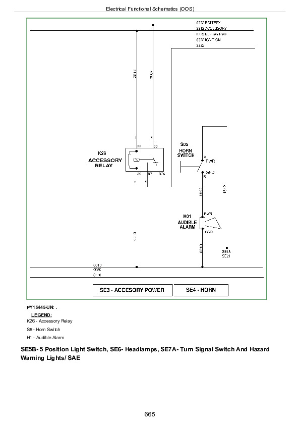
    Electrical Functional Schematics (OOS)……664
Section 245: CONTROL UNITS……673
  Group 05: General References……673
    Reference 245-05-001, Electro-Hydraulic Controller General Information……681
    Reference 245-05-002, Performance Monitor General Operation……683
    Reference 245-05-003, Diagnostic Trouble Code Listing……687
    Reference 245-05-003A, PRF Code List……688
    Reference 245-05-003B, CCU Code List……689
    Reference 245-05-003C, HCU Code List……690
    Reference 245-05-003D, PTR Code List……692
    Reference 245-05-004, Control Unit Addresses……694
    Reference 245-05-004A, CCU Address List……695
    Reference 245-05-004B, HCU Address List……697
    Reference 245-05-004C, PTR Address List……699
    Reference 245-05-005, Programming Control Units……702
    Reference 245-05-006, CAN Network Voltage Checks……709
    Reference 245-05-200, CAN Communication System Theory of Operation……712
    Reference 245-05-201, VIN Security Fault Diagnosis……714
    Reference 245-05-300, CAN Communication System Diagnostic Wiring Diagram Listing……715
    Reference 245-05-301, CAN System Diagnostic Wiring Diagram—Straddle Mount Tractors……716
    Reference 245-05-302, CAN System Diagnostic Wiring Diagram—Isolated Open Operator Station and Cab Tractors……717
    Reference 245-05-303, CAN System Diagnostic Wiring Diagram—OOS Tractors……718
  Group 15: Tests and Adjustments……673
    Reference 245-15-001, Electro-Hydraulic Controller Switched Supply Voltage and Ground Test……721
    Reference 245-15-002, Electro-Hydraulic Controller Unswitched Supply Voltage and Ground Test……723
    Reference 245-15-301, Electro-Hydraulic Controller Power Supply Wiring Diagram—Straddle Mount……725
    Reference 245-15-302, Electro-Hydraulic Controller Power Supply Wiring Diagram—Isolated Open Operator Station and Cab Tractors……726
    Reference 245-15-303, Electro-Hydraulic Controller Power Supply Wiring Diagram—OOS Tractors……727
    A/C Compressor Clutch Coil Test Points……728
    Blower Motor Test Points……730
  Group CCU: CCU (If Equipped)……673
    Reference 245-CCU-001, CCU Control Unit Calibration……744
    Reference 245-CCU-002, CCU Beep Mode Test With Speed Sensors……753
    Reference 245-CCU-003, CCU Beep Mode Test Without Speed Sensors……756
    Reference 245-CCU-004, Hydraulic Oil Temperature Sensor Circuit Test……757
    Reference 245-CCU-005, Engine Speed Sensor Circuit Test……762
    Reference 245-CCU-006, Wheel Speed Sensor Circuit Test……767
    Reference 245-CCU-007, EH MFWD Switch Circuit Test……772
    Reference 245-CCU-008, EH MFWD Solenoid Circuit Test……777
    Reference 245-CCU-009, Brake Switch Assembly Circuit Test……780
    Reference 245-CCU-010, Rear EH PTO Switch Circuit Test……785
    Reference 245-CCU-011, Rear EH PTO Solenoid Circuit Test……789
    Reference 245-CCU-012, Rear EH PTO Speed Sensor Circuit Test……792
    Reference 245-CCU-201, CCU Controller Theory of Operation……796
    Reference 245-CCU-202, Hydraulic Oil Temperature Sensor Theory of Operation……800
    Reference 245-CCU-203, Engine Speed Sensor Theory of Operation……801
    Reference 245-CCU-204, Wheel Speed Sensor Theory of Operation……802
    Reference 245-CCU-205, EH MFWD Switch Theory of Operation……803
    Reference 245-CCU-206, MFWD Solenoid Theory of Operation……804
    Reference 245-CCU-207, Brake Switch Assembly Theory of Operation……805
    Reference 245-CCU-208, Rear EH PTO Switch Theory of Operation……806
    Reference 245-CCU-209, Rear EH PTO Solenoid Theory of Operation……807
    Reference 245-CCU-210, Rear EH PTO Speed Sensor Theory of Operation……808
    Reference 245-CCU-301, Hydraulic Oil Temperature Sensor Diagnostic Wiring Diagram……809
    Reference 245-CCU-302A, Engine Speed Sensor Diagnostic Wiring Diagram—OOS……810
    Reference 245-CCU-302B, Engine Speed Sensor Diagnostic Wiring Diagram—Isolated Open Operator Station and Cab Tractors……811
    Reference 245-CCU-303A, Wheel Speed Sensor Diagnostic Wiring Diagram—Straddle Mount Tractors……812
    Reference 245-CCU-303B, Wheel Speed Sensor Diagnostic Wiring Diagram—Isolated Open Operator Station and Cab Tractors……813
    Reference 245-CCU-304A, MFWD Diagnostic Wiring Diagram—Straddle Mount……814
    Reference 245-CCU-304B, MFWD Diagnostic Wiring Diagram—Isolated Open Operator Station (IOOS) and Cab……815
    Reference 245-CCU-305A, Brake Switch Assembly Diagnostic Wiring Diagram—Straddle Mount Tractors……816
    Reference 245-CCU-305B, Brake Switch Assembly Diagnostic Wiring Diagram—Isolated Open Operator Station and Cab Tractors……817
    Reference 245-CCU-306, Rear EH PTO Switch Diagnostic Wiring Diagram……818
    Reference 245-CCU-307, Rear EH PTO Solenoid Diagnostic Wiring Diagram……819
    Reference 245-CCU-308, Rear EH PTO Speed Sensor Diagnostic Wiring Diagram……820
  Group HCU: HCU (If Equipped)……675
    Reference 245-HCU-001, HCU Control Unit Calibration……833
    Reference 245-HCU-002, HCU Beep Mode Test……845
    Reference 245-HCU-003, Rear Hitch Control Lever Circuit Test……848
    Reference 245-HCU-004, Rear Hitch Raise/Lower Switch Circuit Test……854
    Reference 245-HCU-005, Rear Hitch Height-Limit Control Circuit Test……859
    Reference 245-HCU-006, Rear Hitch Rate-of-Drop Control Circuit Test……864
    Reference 245-HCU-007, Rear Hitch Load/Depth Control Circuit Test……869
    Reference 245-HCU-008, Rear Hitch Left External Switch Circuit Test……874
    Reference 245-HCU-009, Rear Hitch Optional Right External Switch Circuit Test……880
    Reference 245-HCU-010, Rear Hitch Raise Solenoid Circuit Test……885
    Reference 245-HCU-011, Rear Hitch Lower Solenoid Circuit Test……889
    Reference 245-HCU-012, Rear Hitch Position Sensor Circuit Test……893
    Reference 245-HCU-013, Rear Hitch Draft Sensor Circuit Test……898
    Reference 245-HCU-201, HCU Control Unit Theory of Operation……903
    Reference 245-HCU-202, Rear Hitch Control Lever Theory of Operation……907
    Reference 245-HCU-203, Rear Hitch Raise/Lower Switch Theory of Operation……908
    Reference 245-HCU-204, Rear Hitch Height-Limit Control Theory of Operation……909
    Reference 245-HCU-205, Rear Hitch Rate-of-Drop Control Theory of Operation……910
    Reference 245-HCU-206, Rear Hitch Load/Depth Control Theory of Operation……911
    Reference 245-HCU-207, Rear Hitch Left and Optional Right External Switch Theory of Operation……913
    Reference 245-HCU-208, Rear Hitch Raise and Lower Solenoids Theory of Operation……915
    Reference 245-HCU-209, Rear Hitch Position Sensor Theory of Operation……916
    Reference 245-HCU-210, Rear Hitch Draft Sensor Theory of Operation……917
    Reference 245-HCU-301, Rear Hitch Control Assembly Diagnostic Wiring Diagram……918
    Reference 245-HCU-302, Hitch Load/Depth Control Diagnostic Wiring Diagram……919
    Reference 245-HCU-303, Rear Hitch Left External Switch Diagnostic Wiring Diagram……920
    Reference 245-HCU-304, Rear Hitch Optional Right External Switch Diagnostic Wiring Diagram……921
    Reference 245-HCU-305, Rear Hitch Raise and Lower Solenoids Diagnostic Wiring Diagram……922
    Reference 245-HCU-306, Rear Hitch Position Sensor Diagnostic Wiring Diagram……923
    Reference 245-HCU-307, Rear Hitch Draft Sensor Diagnostic Wiring Diagram……924
  Group PTR: PTR (If Equipped)……676
    Reference 245-PTR-001, PTR Control Unit Calibration……952
    Reference 245-PTR-002, PTR Control Unit Beep Mode Test With Speed Sensors……979
    Reference 245-PTR-003, PTR Control Unit Beep Mode Test Without Speed Sensors……983
    Reference 245-PTR-004, Directional Reverser Switch Circuit Test……984
    Reference 245-PTR-005, Clutch Disengaged Switch Circuit Test……988
    Reference 245-PTR-006, Optional Hi/Lo Switch Circuit Test……992
    Reference 245-PTR-007, Optional Infinitely Variable Shuttle Control Circuit Test……997
    Reference 245-PTR-008, Park Switch Circuit Test……1003
    Reference 245-PTR-009, Seat Switch Circuit Test……1008
    Reference 245-PTR-010, Forward Solenoid Circuit Test……1013
    Reference 245-PTR-011, Reverse Solenoid Circuit Test……1016
    Reference 245-PTR-012, Clutch Enable Proportional Valve Circuit Test……1019
    Reference 245-PTR-013, Optional Hi/Lo Solenoid Circuit Test……1023
    Reference 245-PTR-014, Clutch Pedal Position Sensor Circuit Test……1026
    Reference 245-PTR-015, Enable Pressure Sensor Circuit Test……1031
    Reference 245-PTR-016, Countershaft Speed Sensor Circuit Test……1037
    Reference 245-PTR-201, PTR Control Unit Theory of Operation……1042
    Reference 245-PTR-202, Come-Home Mode Theory of Operation……1047
    Reference 245-PTR-203, Directional Reverser Switch Theory of Operation……1048
    Reference 245-PTR-204, Clutch Disengaged Switch Theory of Operation……1049
    Reference 245-PTR-205, Optional Hi/Lo Switch Theory of Operation……1050
    Reference 245-PTR-206, Optional Infinitely Variable Shuttle Control Theory of Operation……1051
    Reference 245-PTR-207, Park Switch Theory of Operation……1052
    Reference 245-PTR-208, Seat Switch Theory of Operation……1053
    Reference 245-PTR-209, Forward Solenoid Theory of Operation……1055
    Reference 245-PTR-210, Reverse Solenoid Theory of Operation……1056
    Reference 245-PTR-211, Clutch Enable Proportional Valve Theory of Operation……1057
    Reference 245-PTR-212, Optional Hi/Lo Solenoid Theory of Operation……1058
    Reference 245-PTR-213, Clutch Pedal Position Sensor Theory of Operation……1059
    Reference 245-PTR-214, Enable Pressure Sensor Theory of Operation……1060
    Reference 245-PTR-215, Countershaft Speed Sensor Theory of Operation……1061
    Reference 245-PTR-301A, Directional Reverser Switch Circuit Diagnostic Wiring Diagram—Straddle Mount Tractors……1062
    Reference 245-PTR-301B, Directional Reverser Switch Circuit Diagnostic Wiring Diagram—Isolated Open Operator Station and Cab Tractors……1063
    Reference 245-PTR-301C, Directional Reverser Switch Circuit Diagnostic Wiring Diagram—OOS……1064
    Reference 245-PTR-302A, Clutch Disengaged Switch Diagnostic Wiring Diagram—Straddle Mount Tractors……1065
    Reference 245-PTR-302B, Clutch Disengaged Switch Diagnostic Wiring Diagram—Isolated Open Operator Station and Cab Tractors……1066
    Reference 245-PTR-302C, Clutch Disengaged Switch Diagnostic Wiring Diagram—OOS……1067
    Reference 245-PTR-303, Optional Hi/Lo Switch and Solenoid Diagnostic Wiring Diagram……1068
    Reference 245-PTR-304A, Optional Infinitely Variable Shuttle Control Diagnostic Wiring Diagram—Straddle Mount Tractors……1069
    Reference 245-PTR-304B, Optional Infinitely Variable Shuttle Control Diagnostic Wiring Diagram—Isolated Open Operator Station and Cab Tractors……1070
    Reference 245-PTR-305A, Park Switch Diagnostic Wiring Diagram—Straddle Mount Tractors……1071
    Reference 245-PTR-305B, Park Switch Diagnostic Wiring Diagram—Isolated Open Operator Station and Cab Tractors……1072
    Reference 245-PTR-306A, Seat Switch Diagnostic Wiring Diagram—Straddle Mount Tractors……1073
    Reference 245-PTR-306B, Seat Switch Diagnostic Wiring Diagram—Isolated Open Operator Station and Cab Tractors……1074
    Reference 245-PTR-306C, Seat Switch Diagnostic Wiring Diagram—OOS……1075
    Reference 245-PTR-307A, Forward Solenoid Diagnostic Wiring Diagram—Straddle Mount Tractors……1076
    Reference 245-PTR-307B, Forward Solenoid Diagnostic Wiring Diagram—Isolated Open Operator Station and Cab Tractors……1077
    Reference 245-PTR-308A, Reverse Solenoid Diagnostic Wiring Diagram—Straddle Mount Tractors……1078
    Reference 245-PTR-308B, Reverse Solenoid Diagnostic Wiring Diagram—Isolated Open Operator Station and Cab Tractors……1079
    Reference 245-PTR-309, Clutch Enable Proportional Valve Diagnostic Wiring Diagram……1080
    Reference 245-PTR-310A, Clutch Pedal Position Sensor Diagnostic Wiring Diagram—Straddle Mount Tractors……1081
    Reference 245-PTR-310B, Clutch Pedal Position Sensor Diagnostic Wiring Diagram—Isolated Open Operator Station and Cab Tractors……1082
    Reference 245-PTR-311, Enable Pressure Sensor Diagnostic Wiring Diagram……1083
    Reference 245-PTR-312A, Countershaft Speed Sensor Diagnostic Wiring Diagram—Straddle Mount Tractors……1084
    Reference 245-PTR-312B, Countershaft Speed Sensor Diagnostic Wiring Diagram—Isolated Open Operator Station and Cab Tractors……1085
    Reference 245-PTR-312C, Countershaft Speed Sensor Diagnostic Wiring Diagram—OOS……1086
Section 245A: CONTROL UNITS (Cab, August 2012, Serial Number: 025651—)……1087
  Group 05: General References (Cab, August 2012, Serial Number: 025651—)……1089
    General References (Cab, August 2012, Serial Number: 025651—)……1089
  Group 15: Tests and Adjustments (Cab, August 2012, Serial Number: 025651—)……1091
    Tests and Adjustments (Cab, August 2012, Serial Number: 025651—)……1091
  Group EHC: CCU and PTR Control Units (Cab, August 2012, Serial Number: 025651—)……1093
    CCU and PTR Control Units (Cab, August 2012, Serial Number: 025651—)……1093
Section 245B: CONTROL UNITS (OOS, August 2012, Serial Number: 025651—)……1094
  Group 05: General References (OOS, August 2012, Serial Number: 025651—)……1094
    General References (OOS)……1097
    Access Control Unit Addresses……1098
    Recall, Record, and Clear Codes……1104
  Group 15: Tests and Adjustments (OOS, August 2012, Serial Number: 025651—)……1094
    Tests and Adjustments (OOS)……1110
  Group CCU: CCU (OOS, August 2012, Serial Number: 025651—)……1094
    CCU (OOS)……1112
  Group ICC: ICC (OOS, August 2012, Serial Number: 025651—)……1094
    Instrument Cluster Control Unit (ICC) Configuration and Calibration……1115
    ICC 000 — Initial Address……1117
    ICC 001 — Recall Diagnostic Codes……1118
    ICC 002 — ICU System Beep Address……1119
    ICC 005 — Switch Status……1121
    ICC 006 — Indicator Status……1122
    ICC 010 — Fuel Level Sender Voltage……1124
    ICC 020 — Units Selection……1125
    ICC 021 — Auto Clear DTC Hours……1126
    ICC 022 — Backlight Dimming Percentage……1127
    ICC 031 — Revert to Hours Status……1128
    ICC 032 — ICC Flash Rate 1……1129
    ICC 033 — ICC Flash Rate 2……1130
    ICC 036 — Engine Coolant Warning Level……1131
    ICC 037 — Engine Coolant Stop Level……1132
    ICC 040 — Fuel Gauge Configuration……1133
    ICC 041 — Resistance Verses Fuel Level Gauge Constant 1……1134
    ICC 042 — Resistance Verses Fuel Level Gauge Constant 2……1135
    ICC 043 — Resistance Verses Fuel Level Gauge Constant 3……1136
    ICC 044 — Resistance Verses Fuel Level Gauge Constant 4……1137
    ICC 045 — Resistance Verses Fuel Level Gauge Constant 5……1138
    ICC 046 — Resistance Verses Fuel Level Gauge Constant 6……1139
    ICC 047 — Resistance Verses Fuel Level Gauge Constant 7……1140
    ICC 048 — Resistance Verses Fuel Level Gauge Constant 8……1141
    ICC 049 — Resistance Verses Fuel Level Gauge Constant 9……1142
    ICC 200-251 — General Control Unit Data……1143
  Group PTR: PTR (OOS, August 2012, Serial Number: 025651—)……1095
    PTR (OOS)……1145
Section 251: COLLARSHIFT AND SYNCSHUTTLE™ Transmissions……1146
  Group 15: Tests and Adjustments……1146
    Check and Adjust Clutch Pedal Free Play……1150
  Group 20: Theory of Operation……1146
    Transmission Theory of Operation Reference Listing……1154
    Clutch Operation—CollarShift and SyncShuttle™ Transmissions (PY008, PY021, CM, TM, AP, TU05, AP05, NM, NP, NM05, NP05)……1155
    Transmission Lubrication System—CollarShift Transmission (PY008)……1163
    Transmission Lubrication System—CollarShift Transmission (PY021)……1164
    Transmission Lubrication System—CollarShift and SyncShuttle™ Transmissions (CM, TM, AP, TU05, AP05, NM, NP, NM05, NP05)……1165
    Gear Shift Power Flow—CollarShift Transmission (PY008)……1167
    Gear Shift Power Flow—CollarShift Transmission (PY021)……1168
    Gear Shift Power Flow—CollarShift Transmission (CM)……1169
    Gear Shift Power Flow—SyncShuttle™ Transmission (TM, AP, TU05, AP05, NM, NP, NM05, NP05)……1171
    Synchronizer Operation—Reverse and 2nd Gear (Disk-and-Plate-Type Synchronizer) (TM, AP, TU05, AP05, NM, NP, NM05, NP05)……1173
    Synchronizer Operation—1st and 3rd Gear (Cone-Type Synchronizer) (TM, AP, TU05, AP05, NM, NP, NM05, NP05)……1175
    Range Shift Power Flow—CollarShift Transmission (PY008)……1177
    Range Shift Power Flow—CollarShift Transmission (PY021)……1178
    Range Shift Power Flow—CollarShift Transmission (CM, TM, AP, TU05, AP05, NM, NP, NM05, NP05)……1179
  Group 25: Schematics and Diagrams……1146
    Transmission Component Location Listing……1182
    Power Train Components—CollarShift and SyncShuttle™ Transmissions (PY008, PY021, AP, NM, NP, NM05, NP05)……1183
    Power Train Components—CollarShift and SyncShuttle™ Transmissions (CM, TM, TU05, AP05)……1184
    Clutch Components—CollarShift and SyncShuttle™ Transmissions (PY008, PY021, CM, TM, AP, TU05, AP05, NM, NP, NM05, NP05)……1185
    Transmission Components—CollarShift Transmission (PY008)……1187
    Transmission Components—CollarShift Transmission (PY021)……1188
    Transmission Components—CollarShift Transmission (CM)……1189
    Transmission Components—SyncShuttle™ Transmission (TM, AP, TU05, AP05, NM, NP, NM05, NP05)……1191
Section 255: PowrReverser™ TRANSMISSION (IF EQUIPPED)……1193
  Group 05: General Information……1193
    Install Test Equipment……1384
  Group 10: Preliminary and Operational Checks……1193
    Transmission Preliminary Checks……1291
    Transmission Operational Checks……1215
  Group 15: Tests and Adjustments……1193
    PowrReverser Control Valve Tests……1226
    PowrReverser Pump Flow Test……1233
    Electro-Hydraulic (EH) Hi/Lo Valve Pressure Test (Not Applicable)……1236
    PowrReverser Main Pressure Relief Valve Adjustment……1240
  Group 20: Theory of Operation……1193
    PowrReverser Transmission Theory of Operation Information Reference Listing……1243
    Mechanical PTO Clutch Operation—Clutch Disengaged……1244
    Mechanical PTO Clutch Operation—Clutch Engaged……1246
    PowrReverser General Information……1248
    PowrReverser Operation in Forward……1249
    PowrReverser Operation in Reverse……1251
    PowrReverser Control Valve Operation—Electro-Hydraulic Directional Reverser in Neutral……1253
    PowrReverser Control Valve Operation—Electro-Hydraulic Directional Reverser in Forward……1255
    PowrReverser Control Valve Operation—Electro-Hydraulic Directional Reverser in Reverse……1257
    Electro-Hydraulic Hi/Lo Valve Operation—Low Position (Not Applicable)……1259
    Electro-Hydraulic Hi/Lo Valve Operation—High Position (Not Applicable)……1261
    PowrReverser Transmission—Gearshift Power Flow……1263
    PowrReverser Transmission—Range Shift Power Flow……1265
    Gearshift Synchronizer Operation……1267
    PowrReverser Transmission Lubrication System……1269
    POWRREVERSER Transmission Lubrication System (With Electro-Hydraulic Hi/Lo) (Not Applicable)……1271
  Group 25: Schematics and Diagrams……1193
    POWRREVERSER Transmission Component Location Listing……1273
    POWRREVERSER Transmission Hydraulic Schematic……1274
    POWRREVERSER Transmission Hydraulic Schematic (With Electro-Hydraulic Hi/Lo) (Not Applicable)……1276
    Power Train Components—Straddle Mount……1278
    Power Train Components—Isolated Open Operator Station and Cab Tractors……1279
    Mechanical PTO Clutch Components……1280
    POWRREVERSER Components……1281
    POWRREVERSER Components (With Electro-Hydraulic Hi/Lo) (Not Applicable)……1282
    Transmission Components……1284
    Transmission Components (With Electro-Hydraulic Hi/Lo) (Not Applicable)……1286
Section 256: DRIVE SYSTEMS……1288
  Group 10: Preliminary and Operational Checks……1288
    Preliminary Checks……1291
    Rear Differential Lock Operational Check……1293
    PTO Operational Checks……1294
    MFWD Operational Checks……1296
  Group 15: Tests and Adjustments……1288
    Adjust PTO Clutch Lever Linkage — OOS……1299
    Adjust PTO Clutch Lever Linkage — IOOS and Cab……1301
    Adjust 540E PTO Lever Linkage—With Throttle Limiter (Synchronized Transmission Only) — If Equipped……1303
    Adjust 540E PTO Lever Linkage—Without Throttle Limiter (Synchronized Transmission Only) — If Equipped……1305
    Park Brake Band Adjustment (If equipped)……1307
    Park Brake Linkage Adjustment (If equipped)……1309
  Group 20: Theory of Operation……1288
    Drive Systems Theory of Operation Reference Listing……1312
    Differential Power Flow……1313
    High Clearance Axle Differential Power Flow……1315
    Differential Lock Operation……1317
    Final Drive Operation……1319
    Mechanical Front Wheel Drive (MFWD) Drop Gearbox Operation……1320
    Mechanical PTO Operation……1322
    540/540E Mechanical PTO Operation……1324
    Park Brake Operation (If Equipped)……1326
  Group 25: Schematics and Diagrams……1288
    Drive Systems Component Location Listing……1329
    Final Drive Components……1330
    High Clearance Final Drive Components……1331
    Mechanical PTO Components……1332
    540/540E Mechanical PTO Components……1333
    Park Brake Components (If equipped)……1334
Section 260: STEERING AND BRAKES……1336
  Group 05: General Information……1336
    Install Test Equipment……1384
  Group 10: Preliminary and Operational Checks……1336
    Steering Preliminary Check……1342
    Steering Operational Check……1343
    Rear Brakes Preliminary Check……1344
    Rear Brake Operational Test……1345
  Group 15: Test and Adjustments……1336
    Steering Pump Flow Test……1348
    Steering Valve Relief Test……1349
    Steering Leak Test……1350
    Checking Toe-In—Adjustable Front Axle……1352
    Adjusting Toe-In—Adjustable Front Axle……1353
    Adjusting Toe-In—Adjustable Front Axle (Narrow Tractors)……1355
    Adjusting Toe-In—Adjustable Front Axle (High Clearance Tractors)……1356
    Checking Toe-In—MFWD Axle……1358
    Adjusting Toe-In—MFWD Axle……1359
    Set MFWD Steering Stops Turning Radius……1360
    Bleed Rear Brakes……1361
    Rear Brake Valve Leak Test……1362
    Brake Pedal Adjustment……1363
    Adjust Brake Retractors……1365
  Group 20: Theory of Operation……1336
    Steering Valve Operation—Neutral and Manual Turning……1368
    Steering Valve Operation—Power Turning……1370
    Brake System Operation……1372
    Brake Valve Operation……1374
Section 270: HYDRAULICS……1378
  Group 05: General Information……1378
    Install Test Equipment……1384
    Hydraulic Oil Warm-Up Procedure……1388
  Group 10: Preliminary and Operational Checks……1378
    Hydraulic System Preliminary Checks……1391
  Group 15: Tests and Adjustments……1378
    Pump Flow Test (Tractors Without SCV)……1395
    Pump Flow Test (Tractors With SCV)……1397
    Main Relief Valve Test (Tractors Without SCV)……1399
    Main Relief Valve Test (Tractors With SCV)……1401
    Rockshaft Load Sense Relief Valve Test……1403
    SCV Leakage Test……1405
    Rockshaft Leakage Test……1407
    Rockshaft Lift Cycle Test……1409
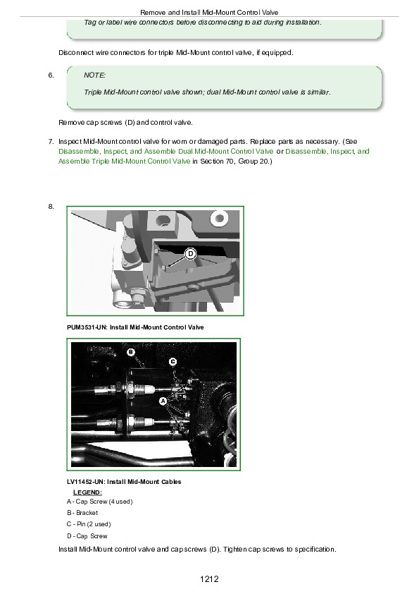
    Mid-Mount Control Valve Cable Adjustment……1411
    Rockshaft Draft-Sensing and Position Control Cable Adjustment……1413
    Rockshaft Lever Friction Adjustment……1414
    Rockshaft Position-Sensing Feedback Linkage Adjustment……1415
    Rockshaft Draft-Sensing Feedback Linkage Adjustment……1419
  Group 20: Theory of Operation……1378
    Hydraulic System Theory of Operation Information Reference Listing……1422
    Hydraulic System Operation……1423
    Hydraulic System Operation—Narrow Tractors……1426
    Hydraulic Filter Operation……1429
    Hydraulic Pump Operation……1431
    Rockshaft Control Valve Operation—Two Flow Regulator Valves……1433
    Rockshaft Control Valve Operation—Neutral Position……1435
    Rockshaft Control Valve Operation—Raise Position……1437
    Rockshaft Control Valve Operation—Lower Position……1439
    Surge Relief Valve Operation……1441
    Rate-of-Drop Valve Operation—Full Open……1443
    Rate-of-Drop Valve Operation—Full Closed……1445
    Rockshaft Draft-Sensing Operation……1447
    SCV Operation (Neutral Position)……1449
    Selective Control Valve Operation—Neutral Position—Narrow Tractors……1451
    Selective Control Valve Operation—Extend and Retract Positions……1453
    Selective Control Valve Operation—Extend and Retract Positions—Narrow Tractors……1455
    Selective Control Valve Operation—Boom Spool Float Position……1457
    Selective Control Valve Operation—Boom Spool Float Position—Narrow Tractors……1459
    Dual Mid-Mount Control Valve Operation—Neutral Position……1461
    Dual Mid-Mount Control Valve Operation—Extend and Retract Positions……1463
    Dual Mid-Mount Control Valve Operation—Float Position……1465
    Dual Mid-Mount Control Valve Operation—Regenerative Position……1467
    Double-Acting Sleeve Coupler Operation……1469
    Double-Acting Sleeve Coupler Operation—Narrow Tractors……1471
    Selective Control Valve Operation—Bucket Spool Regenerative Position……1473
  Group 25: Schematics and Diagrams……1379
    Hydraulic System Schematic Listing……1476
    Legend for Hydraulic Schematic—Without Selective Control Valves……1477
    Legend for Hydraulic Schematic—With Selective Control Valves……1479
    Hydraulic Schematic—Narrow Tractors……1481
    Power Beyond Hydraulic Schematic……1483
    Hydraulic System Schematic—POWRREVERSER POWRREVERSER is a trademark of Deere & Company Transmission (Sheet 1 of 2)……1379
    Hydraulic System Schematic—POWRREVERSER POWRREVERSER is a trademark of Deere & Company Transmission with Electro-Hydraulic Hi/Lo (Sheet 1 of 2) (Not Applicable)……1379
    Hydraulic System Schematic—POWRREVERSER POWRREVERSER is a trademark of Deere & Company Transmission with Mechanical Hitch (Sheet 2 of 2)……1379
    Hydraulic System Schematic—Straddle Mount Tractors With Mid-Mount Valve……1490
Section 290: Operator's Cab……1492
  Group 10: Operational Tests……1492
    Air-Conditioning System, Heater and Operator's Seat——Summary of References……1495
    Air-Conditioning System and Heater—Test Sequence……1496
    Air Comfort Seat—Test Sequence……1501
  Group 15: Tests and Adjustments……1492
    Air-Conditioning System, Heater and Operator's Seat, Test and Adjustments—Summary of References……1504
    Safety at Work……1505
    Handling Refrigerant……1506
    Safety Equipment……1507
    In an Emergency……1508
    Storage of Refrigerant Containers……1509
    R134a Refrigerant……1552
    Important……1511
    A/C ON/OFF Switch and Temperature Control Knob……1512
    Heater Temperature Control Knob……1513
    Essential Tools……1514
    Service Equipment and Tools……1515
    Other Material……1516
    Specifications……1517
    Explanation of Checks……1518
    Adjust Heater Temperature Control Cable……1542
    Adjust A/C Temperature Control Switch……1544
    Pressure Deviations……1546
  Group 20: Theory of Operation……1492
    Air-Conditioning, Heating and Ventilation Systems, Operation—Summary of References……1550
    Principle of Heat Exchange……1551
    R134a Refrigerant……1552
    Refrigerant Circuit Layout……1553
    Functional Description of Components—Refrigerant Circuit……1555
    Functional Description of Components — Compressor……1557
    Functional Description of Components — Condenser……1558
    Functional Description of Components—Receiver-Drier……1559
    Functional Description of Components—Expansion Valve……1560
    Functional Description of Components—Thermostat Switch……1562
    Functional Description of Components—Evaporator……1563
    Functional Description of Components—High/Low Pressure Switch……1564
    Functional Description of Components—Control Knobs for Heating and Cooling……1565
    Heating and Ventilation……1566
Section 299: SERVICE TOOLS……1568
  Group 05: Dealer Fabricated Tools……1568
    DFRW26—Test Lead for Automotive-Style Fuses……1571
    DFRW51—Electronic Circuit Load Tester……1572
    DFRW83—Nozzle Assembly……1573
    DFRW126—Modified Tap Out Harness……1575
    DFRW133—Tap Out Harness……1577
  Group 10: Service Tools and Kits……1568
    AR94522—ISO SCV Coupler……1579
    JDG774—Solenoid Test Harness……1580
    JT02051—Manifold with Gauges……1581
    JT02081—Halogen Leak Detector……1582
    JT02153—Current Clamp-On Probe……1583
    JT03043—Adapter 1/2 M NPT x 1-1/16 M 37°……1584
    JT03044—Adapter 3/4 M NPT x 1-1/16 M 37°……1585
    JT03051—Adapter 1-1/16 F 37° x 1-1/16 F 37°……1586
    JT03059—90° Elbow, 1 1/16-12 M 37° x 1 1/16-12 F 37° Sw……1587
    JT03110—Adapter……1588
    JT03262—Adapter……1589
    JT03345—Gauge……1590
    JT03364—Hose with Coupler……1591
    JT03367—Connector……1592
    JT03459—Adapter 1-3/16 F ORFS x 7/16 37°……1593
    JT03481—Kit……1594
    JT03481-1—Adapter Male Quick Coupler Plug x 1/4 M NPT……1595
    JT03481-3—Straight Fitting 3/4-14 F NPT x M20 x 1.5 ORB……1596
    JT03481-4—Straight Fitting 1/8 M BSPT X 1/8 F NPT……1597
    JT03520—Special Adapter……1598
    JT05473—Gauge w/Quick Coupler, 0-35,000 kPa (0-5000 psi)……1599
    JT05494—7/16-20 M 37° x 3/4-16 M ORB……1600
    JT05498—Hose 508 mm (20 in.)……1601
    JT05634—Pressure Gauge……1602
    JT05685—Battery Load Tester……1603
    JT05690—1 1/16-12 M 37° x 1 3/16-12 F ORFS……1604
    JT05791—Digital Multimeter……1605
    JT05843—Hydrometer……1606
    JT07032—Gauge 400 kPa (60 psi)……1607
    JT07041—Gauge 2800 kPa (400 psi)……1608
    JT07148—Digital Hydraulic Tester……1609
    LVB24862—Wiring Harness……1610
    RE200690—Performance Monitor……1611

John Deere Tractors 5425, 5425HC, 5425N, 5625, 5625HC, 5725, 5725N, 5725HC Diagnosis and Tests Service Technical Manual (TM6033)


INSTANT DOWNLOAD


Posted on

John Deere Tractors Models 5425, 5625, 5725, 5425N, 5725N, 5425HC, 5625HC, 5725HC Repair Manual (TM6032)


INSTANT DOWNLOAD


Complete Repair Technical Manual for John Deere Tractors 5425, 5425HC, 5425N, 5625, 5625HC, 5725, 5725N, with workshop information to maintain, repair, andrebuild like professional mechanics.

John Deere Tractors Models 5425, 5625, 5725; Narrow 5425N, 5725N; Orchard & HC 5425HC, 5625HC, 5725HC workshop technical manual (repair) includes:
* Numbered table of contents easy to use so that you can find the information you need fast.
* Detailed sub-steps expand on repair procedure information
* Numbered instructions guide you through every repair procedure step by step.
* Notes, cautions and warnings throughout each chapter pinpoint critical information.
* Bold figure number help you quickly match illustrations with instructions.
* Detailed illustrations, drawings and photos guide you through every procedure.
* Enlarged inset helps you identify and examine parts in detail.

TM6032 – 5425, 5425 Narrow, 5425 Orchard, 5425 HC, 5625, 5625 HC,5725, 5725 Narrow, 5725 Orchard and 5725 HC Tractors Technical Manual.pdf

PRODUCT DETAILS:
Total Pages: 1,211 pages
File Format: PDF (bookmarked, ToC, Searchable, Printable, high quality)
Language: English

MAIN SECTIONS
 Foreword
   General Information
      Safety
      General Specifications
      Fuel and Lubricants
      Serial Number Locations
      Features and Accessories
   Engine Repair
      Engine
      Cooling System
   Fuel System
      Fuel System
      Air Intake System
      Speed Control Linkage
   Electrical Repair
      Battery, starter and alternator
      Electrical system components
      Wiring Harness
   Power Train Repair
      Clutch Housing
      Clutch Assembly – CollarShift and Synchronized Transmissions (PY)
      Clutch Assembly -PowrReverser™ Transmission (PM)
      Clutch Assembly -PowrReverser™ Transmission (PY)
      CollarShift/SyncShuttle™ Transmission
      PowrReverserPowrReverser is a trademark of Deere & Company (If Equipped)
      PowrReverserPowrReverser is a trademark of Deere & Company Transmission (If Equipped)
      Rear PTO Drive Shaft
      Differential
      Final Drive
      Mechanical Front Wheel Drive
      Creeper Assembly
   Steering and Brake Repair
      Steering Repair
      Brake Repair
   Hydraulic Repair
      Hydraulic pump and filter
      Hydraulic Oil Cooler
      Rockshaft
      Dual Selective Control Valve
      Single Selective Control Valve
      Mid-Mount Selective Control Valve
      Hydraulic Power Beyond
   Miscellaneous Repair
      Front Axle-2WD
      Wheels
      3-Point Hitch
      Fenders
      Hood
      Final Axle Spacers
   Operator Station Repair
      Seat and Support
      Control Console and Panel
      ROLL-GARD®
      Rear Bar-Narrow Tractors
      Cab Components
      Isolated Open Operator Station Components
      Air Conditioning System
      Heating System
   Dealer Fabricated Tools
      Dealer Fabricated Tools

tm6032 – 5425, 5425 Narrow, 5425 Orchard, 5425 HC, 5625, 5625 HC,5725, 5725 Narrow, 5725 Orchard and 5725 HC Tractors

Table of Contents

Foreword

Section 10: General Information

Group 05: Safety

Recognize Safety Information

Understand Signal Words

Follow Safety Instructions

Prepare for Emergencies

Wear Protective Clothing

Protect Against Noise

Handle Fuel Safely—Avoid Fires

Handle Starting Fluid Safely

Keep ROPS Installed Properly

Use Foldable ROPS and Seat Belt Properly

Stay Clear of Rotating Drivelines

Use Steps and Handholds Correctly

Read Operator Manuals for ISOBUS Implements

Use Seat Belt Properly

Operating the Tractor Safely

Limited Use in Forestry Operation

Operating the Loader Tractor Safely

Keep Riders Off Machine

Instructional Seat

Use Safety Lights and Devices

Use a Safety Chain

Transport Towed Equipment at Safe Speeds

Use Caution On Slopes and Uneven Terrain

Freeing a Mired Machine

Avoid Contact with Agricultural Chemicals

Handle Agricultural Chemicals Safely

Handling Batteries Safely

Avoid Heating Near Pressurized Fluid Lines

Remove Paint Before Welding or Heating

Handle Electronic Components and Brackets Safely

Practice Safe Maintenance

Exhaust Filter Cleaning

Work In Ventilated Area

Support Machine Properly

Prevent Machine Runaway

Park Machine Safely

Transport Tractor Safely

Service Cooling System Safely

Service Accumulator Systems Safely

Service Tires Safely

Service Front-Wheel Drive Tractor Safely

Tightening Wheel Retaining Bolts/Nuts

Avoid High-Pressure Fluids

Do Not Open High-Pressure Fuel System

Store Attachments Safely

Dispose of Waste Properly

Group 10: General Specifications

Machine Specifications

Machine Specifications, continued

Machine Specifications, continued

Machine Specifications, continued

Machine Specifications (Narrow Tractors)

Machine Specifications (Narrow Tractors), continued

Machine Specifications (Narrow Tractors), continued

Machine Specifications (Narrow Tractors), continued

Machine Dimensions — OOS

Machine Dimensions — IOOS

Machine Dimensions — Cab

Machine Dimensions (Narrow Tractors)

Estimated Vehicle Speed, Collar Shift Transmissions (PY)

Estimated Vehicle Speed, Synchronized Transmissions (PY)

Estimated Vehicle Speed, PowrReverser™ Transmission (PM), 12 Forward/12 Reverse

Estimated Vehicle Speed, PowrReverser™ Transmission (PY), 12 Forward/12 Reverse

Ground Speed Estimates (Narrow Tractors)

Repair Specifications

Repair Specifications – Cont..

Repair Specifications – Cont..

Repair Specifications – Cont..

Repair Specifications – Cont..

Repair Specifications – Cont..

Repair Specifications – Cont..

Repair Specifications – Cont..

Repair Specifications – Cont..

Service Recommendations for O-Ring Boss Fittings

Service Recommendations for Flat Face O-Ring Seal Fittings

Metric Cap Screw Torque Values—Grade 7

Metric Bolt and Cap Screw Torque Values

Unified Inch Bolt and Cap Screw Torque Values

Abbreviations

Group 20: Fuel and Lubricants

Diesel Fuel Specifications

Lubricity of Diesel Fuel

Diesel Fuel Storage

Do Not Use Galvanized Containers

Fill Fuel Tank

Diesel Engine Oil

Heavy Duty Diesel Engine Coolant

Engine Break – In Oil

Engine Cooling System

Liquid Coolant Conditioner

Transmission and Hydraulic Oil

MFWD Gear Oil

Grease (Specific Application)

Grease

Alternative and Synthetic Lubricants

Lubricant Storage

Group 25: Serial Number Locations

Serial Numbers

Product Identification Number Location

Engine Serial Number Location

Fuel injection pump serial number location

Alternator Identification Number Location

Power Steering Valve Serial Number Location

Transmission Serial Number Location

Front Axle (2WD) Serial Number Location

Mechanical Front Wheel Drive (MFWD) Serial Number Location

Air Conditioning Compressor Serial Number Location

Cab Serial Number Location

Group 30: Features and Accessories

Features and Accessories

Standard Features

Standard Features

Operating Foldable Rops

Fixed ROPS Crossbar

Factory Installed Optional Equipment

Field Installed Optional Kits and Accessories

Section 20: Engine Repair

Group 05: Engine

Service Equipment and Tools

Specifications

John Deere Engine Repair—Use CTM104

Remove Engine

Install Engine

Group 10: Cooling System

Specifications

Engine Coolant Pump Repair—Use CTM104

Remove right-side fan guard

Remove left-side fan guard

Remove and Install Coolant Recovery Tank

Remove and Inspect Radiator

Install Radiator

Remove and Install Thermostat

Inspect and Replace Belt Tensioner

Section 30: Fuel System

Group 05: Fuel System

Injection Pump, Nozzle and Governor Repair—Use CTM104

Remove, Inspect and Install Fuel Tank—Reference Listing

Remove, Inspect and Install Fuel Tank—OOS ( -XXXXXX)

Remove, Inspect and Install Fuel Tank—OOS (XXXXXX- )

Remove and Install Fuel Tank—Cab and IOOS

Remove, Inspect, and Install Fuel Tank – PowrReverser™ Transmission (PY)

Remove, Inspect, and Install Fuel Tank—Narrow

Replace Fuel Filter (Engine Tier 0 and 1)

Replace Fuel Filter/Water Separator (Engine Tier 2)

Remove and Install Fuel Filter/Primer Pump Assembly (Engine Tier 0 and 1)

Remove and Install Fuel Filter/Primer Pump Assembly (Engine Tier 2)

Remove and Install The Water Separator Assembly—OOS and Cab

Replace Primary Fuel Filter—Cab and IOOS

Replace Fuel Transfer Pump—Cab and IOOS

Replacing the Check Valve in the Fuel Line—Cab and IOOS

Replacing the Adapter in the Fuel Line—Cab and IOOS

Group 10: Air Intake System

Turbocharger Repair—Use CTM104

Specifications

Other Material

Remove, Inspect, and Install Air Cleaner Elements

Remove Turbocharger

Install Turbocharger

Turbocharger Break-In

Group 15: Speed Control Linkage

Inspect and Repair Speed Control Linkage—Reference Listing

Inspect and Repair Speed Control Linkage (OOS)

Inspect and Repair Speed Control Linkage (IOOS and Cab)

Section 40: Electrical Repair

Group 05: Battery, starter and alternator

Starter Repair—Use CTM77

Prevent Battery Explosions

Remove and Install Battery

Remove and Install Starter

Replace Alternator/Regulator

Group 10: Electrical system components

Essential Tools

Other Material

Specifications

Replace Air Filter Restriction Switch

Replace Cold Start Advance Switch

Replace Coolant Temperature Sender

Replace Engine Speed Sensor

Replace Engine Oil Pressure Switch

Replace Key Switch—Reference Listing

Replace Key Switch—OOS and IOOS

Replace Key Switch—Cab

Replace Light Switch

Replace Light Switch — Cab

Replace Turn Signal Switch—Reference Listing

Replace Turn Signal Switch—OOS and IOOS

Replace Turn Signal Switch—Cab

Replace Instrument Panel—Reference Listing

Replace Instrument Panel—OOS and IOOS

Replace Instrument Panel—Cab

Replace Rear PTO Switch—Reference Listing

Replace Rear Mechanical PTO Switch—OOS

Replace Rear Mechanical PTO Switch—Cab and IOOS

Replace Neutral Start Switch

Replace Fuel Level Sender—Reference Listing

Replace Fuel Level Sender—OOS

Replace Fuel Level Sender—Cab and IOOS

Replace Seat Switch—Reference Listing

Replace Seat Switch—OOS (if equipped)

Replace Seat Switch—Cab and IOOS (if Equipped)

Replace Wiper Control Switch

Replace Wiper Motor

Replace Speakers

Replace Antenna

Replace Blower Control Switch

Replace A/C On/Off Switch

Replace A/C Temperature Control Switch

Replace Blower Motor Resistor

Replace Air Conditioning High/Low Pressure Switch

Replace Dome Light

Replace Door Switch

Replace Start Relay

Replace Countershaft Speed Sensor—PowrReverser PowrReverser is a trademark of Deere & Company (PM) and PowrReverser PowrReverser is a trademark of Deere & Company (PY) Tractors (if equipped)

Replace Enable Pressure Sensor—PowrReverser PowrReverser is a trademark of Deere & Company (PM) and PowrReverser PowrReverser is a trademark of Deere & Company (PY) Transmission (if equipped)

Replace Clutch Pedal Position Sensor—PowrReverser PowrReverser is a trademark of Deere & Company (PM) and PowrReverser PowrReverser is a trademark of Deere & Company (PY) Transmission (if equipped)

Replace Clutch Disengage Switch— PowrReverser PowrReverser is a trademark of Deere & Company (PM) and PowrReverser PowrReverser is a trademark of Deere & Company (PY) Transmission (If Equipped)

Replace Electro-Hydraulic Directional Reverser— PowrReverser PowrReverser is a trademark of Deere & Company (PM) and PowrReverser PowrReverser is a trademark of Deere & Company (PY) Transmission (If Equipped)

Replace Park Switch— PowrReverser PowrReverser is a trademark of Deere & Company (PM) and PowrReverser PowrReverser is a trademark of Deere & Company (PY) Transmission (If Equipped)

Replace Brake Pedal Switch—Electro-Hydraulic Tractors (If Equipped)

Replace Trans Forward Solenoid—POWRREVERSER POWRREVERSER is a trademark of Deere & Company Transmission (If Equipped)

Replace Trans Reverse Solenoid—POWRREVERSER POWRREVERSER is a trademark of Deere & Company Transmission (If Equipped)

Replace Electro-Hydraulic Controller – Cab (If equipped with PowrReverser PowrReverser is a trademark of Deere & Company Transmission)

Replace Electrohydraulic Controller— OOS Tractors PowrReverser™ Transmission (If Equipped)

Replace VEC Load Center— OOS Tractors

Group 15: Wiring Harness

Service Equipment and Tools

Essential Tools

Service Parts Kits

Replace Connector Body—Blade Terminals

Replace WEATHER PACK WEATHER PACK is a trademark of Packard Electric. Connector

Install WEATHER PACK WEATHER PACK is a trademark of Packard Electric. Contact

Repair (Pull Type) Metri-Pack® Connectors

Repair (Push Type) Metri-Pack® Connectors

Replace Front Wiring Harness—OOS

Replace Rear Wiring Harness—OOS, CollarShift and Synchronized Transmissions

Replace Rear Wiring Harness—OOS, PowrReverser PowrReverser is a trademark of Deere & Company Transmission (PM)

Replace Wiring Harness— IOOS

Replace Rear Electrical Harness—Cab, CollarShift and Synchronized Transmissions

Replace Console Wiring Harness – Cab, PowrReverser PowrReverser is a trademark of Deere & Company Transmission (PM)

Replace Rear Wiring Harness – Cab, Mechanical Hitch, PowrReverser PowrReverser is a trademark of Deere & Company Transmission (PM)

Replace Cab Roof Electrical Harness

Section 50: Power Train Repair

Group 05: Clutch Housing

Service Equipment and Tools

Other Material

Specifications

Separate Engine from Clutch Housing—Reference Listing

Separate Engine from Clutch Housing—OOS and IOOS

Separate Engine from Clutch Housing—Cab

Install Engine to Clutch Housing—Reference Listing

Install Engine to Clutch Housing—OOS and IOOS

Install Engine to Clutch Housing—Cab

Inspect and Repair Clutch Pedal and Linkage—Reference Listing

Inspect and Repair Clutch Pedal and Linkage (OOS)

Inspect and Repair Clutch Pedal and Linkage (IOOS and Cab)

Inspect and Repair Clutch Pedal and Linkage—(PowrReverser™ (PY) Transmissions)

Group 10: Clutch Assembly — CollarShift and Synchronized Transmissions (PY)

Essential Tools

Service Equipment and Tools

Other Material

Specifications

Remove and Install Clutch Assembly

Disassemble and Inspect Clutch Assembly

Assemble Clutch Assembly

Traction Clutch Finger Adjustment

PTO Clutch Finger Adjustment

Remove and Inspect Clutch Release Mechanism and Shafts

Install Clutch Release Mechanism and Shafts

Group 11: Clutch Assembly —PowrReverser™ Transmission (PM)

Essential Tools

Service Equipment and Tools

Other Material

Specifications

Service Parts Kits

Remove and Install PowrReverser (PM) Clutch Assembly

Disassemble and Inspect Clutch Assembly

Assemble Clutch Assembly

PTO Clutch Finger Adjustment—PowrReverser

Remove and Inspect Clutch Release Mechanism and Shafts—PowrReverser

Install Clutch Release Mechanism and Shafts

Remove, Inspect, and Repair Transmission Pump

Group 12: Clutch Assembly —PowrReverser™ Transmission (PY)

Specifications

Remove and Install PowrReverser Clutch Assembly

Remove, Inspect, and Repair Transmission Pump

Group 15: CollarShift/SyncShuttle™ Transmission

John Deere Transmission Repair

Essential Tools

Service Equipment and Tools

Other Material

Specifications

Separate Clutch Housing from Transmission—Reference Listing

Separate Clutch Housing from Transmission — Open Operator Station ( -XXXXXX)

Separate Clutch Housing from Transmission — Open Operator Station (XXXXXX- )

Separate Clutch Housing from Transmission—IOOS and Cab

Separate Clutch Housing from Transmission—Narrow Tractors

Install Clutch Housing to Transmission—Reference Listing

Install Clutch Housing to Transmission — Open Operator Station ( -XXXXXX)

Install Clutch Housing to Transmission — Open Operator Station (XXXXXX- )

Install Clutch Housing to Transmission—IOOS and Cab

Install Clutch Housing to Transmission—Narrow Tractors

Inspect and Repair Gear and Range Shift Levers – Reference Listing

Inspect and Repair Gear Shift Lever (RH)

Inspect and Repair Gear Shift Lever – Narrow Tractor

Inspect and Repair Gear and Range Shift Levers (RH)

Inspect and Repair Range Shift Lever (LH)

Inspect and Repair Range Shift Lever – Narrow Tractor

Remove Transmission—Reference Listing

Remove Transmission – CollarShift and Synchronized Transmissions (PY)

Remove Transmission – CollarShift and Synchronized Transmissions (CM, TM, TU05, AP, AP05)

Remove Transmission – Synchronized Transmissions (NM, NP, NM05, NP05)

Disassemble and Inspect Transmission—Reference Listing

Disassemble and Inspect Transmission (CM, TM, TU05, AP05)

Disassemble and Inspect Transmission (AP)

Disassemble and Inspect Transmission (NM, NP, NM05, NP05)

Assemble Transmission—Reference Listing

Assemble Transmission (CM, TM, TU05, AP05)

Assemble Transmission (AP)

Assemble and Install Transmission (NM, NP, NM05, NP05)

Install Transmission—Reference Listing

Install Transmission (PY)

Install Transmission (CM, TM, AP, TU05, AP05)

Disassemble, Inspect and Assemble Gear Shift Shaft Assemblies—Reference Listing

Disassemble, Inspect and Assemble Gear Shift Shaft Assemblies (CM, TM, AP, TU05, AP05)

Disassemble, Inspect and Assemble Gear Shift Shaft Assemblies (NM, NP, NM05, NP05)

Disassemble, Inspect, and Assemble Transmission Top Shaft—Reference Listing

Disassemble, Inspect, and Assemble Transmission Top Shaft (CM)

Disassemble, Inspect, and Assemble Transmission Top Shaft (TM, AP, TU05, AP05)

Disassemble, Inspect, and Assemble Transmission Top Shaft (NM, NP, NM05, NP05)

Disassemble, Inspect, and Assemble Range Reduction Shaft—Reference Listing

Disassemble, Inspect, and Assemble Range Reduction Shaft (CM, TM, AP, TU05, AP05)

Disassemble, Inspect, and Assemble Range Reduction Shaft (NM, NP, NM05, NP05)

Disassemble, Inspect and Assemble Driven Shaft—Reference Listing

Disassemble, Inspect and Assemble Driven Shaft (CM, TM, AP, TU05, AP05)

Disassemble, Inspect, and Assemble Driven Shaft (NM, NP, NM05, NP05)

Remove, Inspect, and Install MFWD and Range Gears—Reference Listing

Remove, Inspect, and Install MFWD and Range Gears (CM, TM, AP, TU05, AP05)

Remove, Inspect, and Install MFWD and Range Gears (NM, NP, NM05, NP05)

Remove, Inspect, and Install Reverse Idler Shaft—Reference Listing

Remove, Inspect, and Install Reverse Idler Shaft (CM, TM, AP, TU05, AP05)

Inspect and Repair Park Brake Lever (if equipped)

Remove, Inspect, and Repair Park Brake (if equipped)

Group 16: PowrReverserPowrReverser is a trademark of Deere & Company (If Equipped)

PowrReverser™ Transmission Identification

Essential Tools

Service Equipment and Tools

Other Material

Specifications

Remove and Install PowrReverser (PM) Control Valve (If Equipped)

Remove and Install PowrReverser (PY) Control Valve (If Equipped)

Disassemble, Inspect, and Repair PowrReverser (PM) Control Valve (If Equipped)

Disassemble, Inspect, and Repair PowrReverser (PY) Control Valve (If Equipped)

Remove and Install PowrReverser (PM) and PowrReverser (PY) (If Equipped)

Disassemble, Inspect, and Repair Reverse Idle Gear

Disassemble, Inspect, and Repair Clutch Gear for PowrReverser (PM)

Disassemble, Inspect, and Repair Clutch Gear for PowrReverser (PY)

Disassemble, Inspect, and Repair Driven Shaft

Disassemble, Inspect, and Repair PowrReverser (PM) (If Equipped)

Disassemble, Inspect, and Repair PowrReverser (PY) (If Equipped)

Group 17: PowrReverserPowrReverser is a trademark of Deere & Company Transmission (If Equipped)

John Deere Transmission Repair

Remove Transmission

Disassemble and Inspect Transmission

Assemble Transmission

Install Transmission

Disassemble, Inspect, and Assemble Gearshift Shaft Assemblies

Disassemble, Inspect, and Assemble Transmission Bottom Shaft

Disassemble, Inspect, and Assemble Range Reduction Shaft

Disassemble, Inspect, and Assemble Top Shaft

Remove, Inspect, and Install MFWD and Range Gears

Group 20: Rear PTO Drive Shaft

Service Equipment and Tools—Reference Listing

Service Equipment and Tools

Other Material—Reference Listing

Other Material

Specifications—Reference Listing

Specifications

Inspect and Repair Rear PTO Lever and Linkage—Reference Listing

Inspect and Repair Rear Mechanical PTO Lever and Linkage (OOS)

Inspect and Repair Rear Mechanical PTO Lever and Linkage (IOOS and Cab)

Inspect and Repair PTO Lever and Linkage (Narrow Tractors)

Inspect and Repair PTO 540/540E Shift Lever and Linkage (OOS) — If Equipped

Disassemble and Assemble PTO 540E Shift Lever and Linkage (OOS) — If Equipped

Inspect and Repair PTO 540/540E Shift Lever and Linkage (IOOS and Cab)

Inspect and Repair PTO 540/540E Shift Lever and Linkage (Narrow Tractors)

Remove and Install Rear PTO Drive Shaft Assembly—Reference Listing

Remove and Install Standard and 540/540E Rear PTO Drive Shaft Assembly

Disassemble, Inspect and Assemble Rear PTO Drive Shaft Assembly—Reference Listing

Disassemble, Inspect and Assemble Standard Rear PTO Drive Shaft Assembly

Disassemble, Inspect, and Assemble Rear 540/540E PTO Drive Shaft Assembly

Group 25: Differential

Essential Tools—Reference Listing

Essential Tools

Service Equipment and Tools—Reference Listing

Service Equipment and Tools

Other Material—Reference Listing

Other Material

Specifications—Reference Listing

Specifications

Service Parts Kits—Reference Listing

Service Parts Kits

Remove and Install Differential Assembly—Reference Listing

Remove and Install Differential Assembly

Disassemble, Inspect, and Assemble Differential Assembly—Reference Listing

Disassemble, Inspect, and Assemble Differential Assembly

Remove and Inspect Differential Drive Shaft—Reference Listing

Remove and Inspect Differential Drive Shaft

Install Differential Drive Shaft—Reference Listing

Install Differential Drive Shaft

Remove, Inspect, and Install Differential Lock Assembly—Reference Listing

Remove, Inspect, and Install Differential Lock Assembly (OOS)

Remove, Inspect, and Install Differential Lock Assembly (IOOS and Cab)

Differential Cone Point Adjustment—Reference Listing

Differential Cone Point Adjustment

Differential Backlash Adjustment—Reference Listing

Differential Backlash Adjustment

Group 30: Final Drive

Service Equipment and Tools

Other Material

Remove and Install Final Drive Assembly—Reference Listing

Remove and Install Final Drive Assembly

Remove Final Drive Assembly (High Clearance Tractors)

Install Final Drive Assembly (High Clearance Tractors)

Remove and Install Final Drive Assembly (Narrow Tractors)

Remove and Inspect Planetary Drive Assembly

Install Planetary Drive Assembly

Remove, Inspect, and Install Axle Shaft Assembly

Group 35: Mechanical Front Wheel Drive

Special or Essential Tools

Tools

Other Material

Inspect and Repair MFWD Lever and Linkage—Reference Listing

Inspect and Repair MFWD Lever and Linkage (Narrow Tractors)

Inspect and Repair MFWD Lever and Linkage (OOS)

Inspect and Repair MFWD Lever and Linkage (IOOS and Cab)

Remove and Install MFWD Drop Gearbox

Disassemble and Inspect MFWD Drop Gearbox

MFWD Drop Gearbox Cross Section

Assemble MFWD Drop Gearbox

Remove, Inspect and Install MFWD Drive Shaft—Reference Listing

Remove, Inspect and Install MFWD Drive Shaft

Remove, Inspect, and Install MFWD Drive Shaft (Narrow Tractors)

Remove and Install MFWD Axle Housing Assembly—Reference Listing

Remove and Install MFWD Axle Housing Assembly

Remove and Install MFWD Axle Housing Assembly (Narrow Tractors)

Remove and Install MFWD Axle Pivot Pin and Pivot Bushings (Narrow Tractors)

Remove, Inspect and Install MFWD Axle Supports—Reference Listing

Remove, Inspect and Install MFWD Axle Supports

Remove, Inspect and Install MFWD Axle Supports (High Clearance Tractors)

Disassemble and Inspect MFWD Outer Drive—Reference Listing

Disassemble and Inspect MFWD Outer Drive

Disassemble and Inspect MFWD Outer Drive (High Clearance Tractors)

Disassemble and Inspect MFWD Outer Drive (Narrow Tractors)

Assemble MFWD Outer Drive—Reference Listing

Assemble MFWD Outer Drive

Assemble MFWD Outer Drive (High Clearance Tractors)

Assemble MFWD Outer Drive (Narrow Tractors)

Remove, Inspect and Install MFWD Knuckle Housing—Reference Listing

Remove, Inspect and Install MFWD Knuckle Housing

Repair the Knuckle Housing and the King Pin (High Clerance Tractors)

Repair the Knuckle Housing and the King Pin (Narrow Tractors)

Remove, Inspect, and Install MFWD Axle Shaft—Reference Listing

Remove, Inspect, and Install MFWD Axle Shaft

Remove, Inspect, and Install MFWD Axle Shaft (High Clearance Tractors)

Remove, Inspect, and Install MFWD Axle Shaft (Narrow Tractors)

Remove and Install MFWD Differential Carrier Assembly

Disassemble and Inspect MFWD Differential Carrier Assembly

Assemble MFWD Differential Carrier Assembly

Filling/Draining Planetary Drive

Filling/Draining MFWD Axle Housing

Group 40: Creeper Assembly

Other Material

Remove and Install Creeper Assembly

Disassemble, Inspect, and Assemble Creeper Assembly

Section 60: Steering and Brake Repair

Group 05: Steering Repair

Other Material

Specifications

Service Parts Kits

Remove and Install Steering Column and Valve—Reference Listing

Remove and Install Straight Steering Column and Valve (without oil cooler)

Remove and Install Tilt Steering Column (if equipped)

Remove and Install Steering Valve (with oil cooler)

Disassemble and Inspect Steering Valve

Assemble Steering Valve

Remove and Install Steering Cylinder—Reference Listing

Remove and Install Steering Cylinder—2WD Axle

Remove and Install Steering Cylinder—2WD Axle (Narrow Tractors)

Remove and Install Steering Cylinder—2WD Axle (High Clearance Tractors)

Disassemble, Inspect, and Assemble Steering Cylinder—Reference Listing

Disassemble, Inspect, and Assemble Steering Cylinder—2WD Axle

Disassemble, Inspect, and Assemble Steering Cylinder—2WD Axle (Narrow Tractors)

Disassemble, Inspect, and Assemble Steering Cylinder—2WD Axle (High Clearance Tractors)

Remove and Install Steering Cylinder—MFWD Axle—Reference Listing

Remove and Install Steering Cylinder—MFWD Axle

Remove and Install Steering Cylinder—MFWD Axle (Narrow Tractors)

Disassemble, Inspect, and Assemble Steering Cylinder—MFWD Axle—Reference Listing

Disassemble, Inspect, and Assemble Steering Cylinder—MFWD Axle—Use CTM4870

Disassemble, Inspect, and Assemble Steering Cylinder— MFWD Axle (Narrow Tractors)

Remove, Inspect and Install Tie Rod Assembly—2WD Axle—Reference Listing

Remove, Inspect and Install Tie Rod Assembly—2WD Axle

Remove, Inspect and Install Tie Rod Assembly—2WD Axle (High Clearance Tractors)

Remove, Inspect and Install Tie Rod Assembly—2WD Axle (Narrow Tractors)

Remove, Inspect and Install Tie Rod Assembly—MFWD Axle—Reference Listing

Remove, Inspect and Install Tie Rod Assembly—MFWD Axle

Remove, Inspect and Install Tie Rod Assembly—MFWD Axle (Narrow Tractors)

nspect and Replace Steering Hydraulic Lines—Reference Listing

Inspect and Replace Steering Hydraulic Lines—without oil cooler (5425)

Inspect and Replace Steering Hydraulic Lines—with oil cooler (5625 and 5725)

Steering Hydraulic Lines—with oil cooler (5625 and 5725)

Inspect and Replace Steering Hydraulic Lines—Cab Tractors (With Oil Cooler)

Group 10: Brake Repair

Other Material

Remove and Install Brake Valve and Pedals

Disassemble and Inspect Brake Valve

Brake Valve Cross Section

Assemble Brake Valve

Remove and Inspect Brakes

Install Brakes

Inspect and Replace Brake Hydraulic Lines

Section 70: Hydraulic Repair

Group 05: Hydraulic pump and filter

Service Parts Kit

Service Equipment and Tools

Specifications

Remove, Inspect, and Install Hydraulic Oil Pick-Up Screen

Remove and Install Hydraulic Pump

Remove Hydraulic Pump External Components

Disassemble and Inspect Hydraulic Pump

Assemble Hydraulic Pump

Install Hydraulic Pump External Components

Remove and Install Hydraulic Oil Filter/Manifold

Inspect and Replace Hydraulic Supply/Return Lines

Group 06: Hydraulic Oil Cooler

Remove, Inspect, and Install Hydraulic Oil Cooler—Reference Listing

Remove, Inspect, and Install Hydraulic Oil Cooler

Remove, Inspect, and Install Hydraulic Oil Cooler (If equipped with air conditioning)

Group 10: Rockshaft

Other Material

Service Parts Kits

Inspect and Repair Rockshaft Control Lever Assembly—Reference Listing

Inspect and Repair Rockshaft Control Lever Assembly

Inspect and Repair Rockshaft Control Lever Assembly (Narrow Tractors)

Inspect and Repair Rockshaft Control Linkage

Inspect and Repair Rockshaft Control Lever Assembly(PowrReverser™ Transmission (PY))

Inspect and Repair Rockshaft Control Linkage

Inspect and Repair Draft Sensing Support Assembly

Replace Main Relief Valve

Replace Rockshaft Surge Relief Valve

Remove, Inspect, and Install Rate-of-Drop Valve

Replace Rockshaft Control Valve

Remove and Install Rockshaft Case

Remove, Inspect, and Install Rockshaft Lift Arms

Remove, Inspect, and Install Rockshaft Piston and Cylinder

Group 15: Dual Selective Control Valve

Other Material

Service Parts Kits

Remove and Install Dual Selective Control Valve (SCV)

Disassemble, Inspect, and Assemble Dual Selective Control Valve (SCV)

Inspect and Replace Hydraulic Hoses—Dual Selective Control Valve (SCV)

Group 16: Single Selective Control Valve

Other Material

Service Parts Kits

Inspect and Repair SCV Levers and Linkage (OOS)

Inspect and Repair SCV Levers and Linkage (IOOS and Cab)

Remove and Install Single Selective Control Valve (SCV)—Reference Listing

Remove and Install Single Selective Control Valve (SCV)

Remove and Install Selective Control Valve (SCV) (Narrow Tractors)

Disassemble, Inspect and Assemble Single (Third) Selective Control Valve (SCV)—Reference Listing

Disassemble, Inspect, and Assemble Single (Third) Selective Control Valve (SCV)

Inspect and Replace Hydraulic Hoses—Single (Third) Selective Control Valve (SCV)

Disassemble, Inspect, and Assemble Selective Control Valve (SCV)—Narrow Tractors

Group 17: Mid-Mount Selective Control Valve

Service Parts Kits

Other Material

Specifications

Inspect and Repair Joystick and Linkage

Remove and Install Mid-Mount Control Valve

Disassemble, Inspect, and Assemble Dual Mid-Mount Control Valve

Disassemble, Inspect, and Assemble Triple Mid-Mount Control Valve

Inspect and Replace Hydraulic Lines on Dual or Triple Mid-Mount Control Valve

Inspect and Replace Hydraulic Lines on Dual Mid-Mount Control Valve With Rear SCV

Group 20: Hydraulic Power Beyond

Remove and Install Hydraulic Lines and Fittings—Power Beyond Hook-Up—Reference Listing

Remove and Install Hydraulic Lines and Fittings—Power Beyond Hook-Up

Install and Remove Hydraulic Lines and Fittings—Power Beyond Hook-Up (Narrow Tractors)

Section 80: Miscellaneous Repair

Group 05: Front Axle—2WD

Remove and Install Front Axle—2WD—Reference Listing

Remove and Install Front Axle—2WD

Remove and Install Front Axle—2WD (Narrow Tractors)

Remove and Install Front Axle—2WD (High Clearance Tractors)

Inspect and Replace Pivot Pin and Bushings—2WD Axle

Remove and Install Spindle Assembly—2WD Axle—Reference Listing

Remove and Install Spindle Assembly—2WD Axle

Remove and Install Spindle Assembly—2WD Axle (Narrow Tractors)

Remove and Install Spindle Assembly—2WD Axle (High Clearance Tractors)

Inspect and Replace Spindle Shaft Bushings—2WD Axle

Group 10: Wheels

Inspect and Replace Front Wheel Bearings—Reference Listing

Inspect and Replace Front Wheel Bearings – 2WD

Inspect and Replace Front Wheel Bearings—2WD (Narrow Tractors)

Inspect and Replace Front Wheel Bearings—2WD (High Clearance Tractors)

Group 15: 3-Point Hitch

Inspect and Repair Draft Links—Reference Listing

Inspect and Repair Fixed Draft Links (if equipped with sway chain)

Inspect and Repair Fixed Draft Links (if equipped with adjustable stabilizer bar)

Inspect and Repair Telescoping Draft Links (if equipped with sway chain)

Inspect and Repair Telescoping Draft Links (if equipped with adjustable stabilizer bar)

Inspect and Repair Draft Links (Narrow Tractors)

Inspect and Repair Lift Link—Reference Listing

Inspect and Repair Standard Lift Link

Inspect and Repair Adjustable Lift Link

Inspect and Repair Adjustable Lift Links (Narrow Tractors)

Inspect and Repair Center Link—Reference Listing

Inspect and Repair Center Link

Inspect and Repair Center Link (Narrow Tractors)

Remove and Install Drawbar and Support—Reference Listing

Remove and Install Drawbar and Support

Drawbar and Support (Continued)

Remove and Install Drawbar and Support (Narrow Tractors)

Group 20: Fenders

Remove and Install Fenders—Reference Listing

Remove and Install Fenders–– IOOS Tractors

Remove and Install Fenders—Cab Tractors

Remove and Install Fenders—Narrow Tractors

Group 25: Hood

Remove and Install Hood

Group 30: Final Axle Spacers

Prepare Tractor

Install Axle Spacers

Section 90: Operator Station Repair

Group 05: Seat and Support

Remove and Install Seat and Support—Reference Listing

Remove and Install Seat and Support—OOS

Remove and Install Seat and Support—Cab and IOOS

Group 06: Control Console and Panel

Remove and Install Right-Side Control Console and Panel (OOS)

Remove and Install Left-Side Control Console and Panel (OOS)

Remove and Install Cowl Cover

Group 10: ROLL-GARD®

Remove and Install Roll-Gard™—Reference Listing

Remove and Install Roll-Gard™ (OOS)

Remove and Install Roll-Gard™ (IOOS)

Remove and Install Roll-Gard™ (Narrow Tractors)

Group 12: Rear Bar—Narrow Tractors

Remove and Install Rear Bar

Group 15: Cab Components

Essential Tools

Service Equipment and Tools

Other Material

Specifications

Remove, Inspect, and Install Cab Interior Recirculating Air Filters

Remove, Inspect, and Install Exterior Cab Intake Air Filter

Remove and Install Headliner

Remove and Install Left-Side Upholstery

Remove and Install Right-Side Upholstery

Remove and Install Windshield

Remove and Install Front Lower Windows

Remove and Install Rear Lower Window

Remove and Install Rear Upper Window

Remove and Install Side Windows

Remove and Install Cab Doors

Remove and Install Cab Outer Roof

Remove and Install A/C Housing Inner Roof

Remove Cab

Install Cab

Group 16: Isolated Open Operator Station Components

Other Material

Specifications

Remove Isolated Open Operator Station

Install Isolated Open Operator Station

Group 20: Air Conditioning System

Essential Tools

Service Equipment and Tools

Other Material

Specifications

Service Parts Kits

Recover/Recycle Air Conditioning Refrigerant

Replace Air Conditioning Receiver/Dryer

Remove, Inspect, and Install Air Conditioning Condenser

Remove, Inspect, and Install Air Conditioning Compressor

Test Volumetric Efficiency of Compressor

Test Compressor Shaft Seal Leakage

Disassemble and Assemble Compressor Clutch

Disassemble, Inspect, and Assemble Compressor

Check Compressor Clutch Hub Clearance

Inspect Compressor Manifold

Remove and Install Compressor Relief Valve

Remove and Install HVAC Housing Cover

Remove Blower Motors

Remove Evaporator/Heater Core

Leak Test Evaporator/Heater Core

Install Evaporator/Heater Core

Service Expansion Valve

Expansion Valve Bench Test

Refrigerant Oil Information

Check Compressor Oil Charge

Determine Correct Refrigerant Oil Charge

Add Refrigerant Oil to System

System Information

Flush Air Conditioning System

Evacuate Air Conditioning System

Charge Air Conditioning System

Group 25: Heating System

Replace Heater Temperature Control Cable

Remove Heater Control Valve

Leak Test Heater Control Valve

Install Heater Control Valve

Section 290: Dealer Fabricated Tools

Group 00: Dealer Fabricated Tools

PTO Clutch Finger Height Gauge

Traction Clutch Finger Height Gauge

Traction Clutch Finger Height Adjustment Tool

DFLV1A Final Drive Turning Tool

DFRW20—Compressor Holding Fixture

John Deere Tractors Models 5425, 5625, 5725, 5425N, 5725N, 5425HC, 5625HC, 5725HC Repair Manual (TM6032)


INSTANT DOWNLOAD


Posted on

John Deere 5225, 5325, 5425, 5525 and 5625 Tractors Operator’s Manual (OMRE260579)


INSTANT DOWNLOAD


Complete service Operator’s Manual for John Deere 5225, 5325, 5425, 5525 and 5625 Tractors.

OMRE260579 – John Deere 5225, 5325, 5425, 5525 and 5625 Tractors Operator’s Manual (North American).pdf
omre267252 English – 5603 Tractor Operator’s Manual (North American) Operator’s Manual
omre260580 English – 5225, 5325, 5425, 5525 and 5625 Tractors Maintenance Guide (North American) Maintenance Guide.pdf
omre267253 English – 5603 Tractor Maintenance Guide (North American) Maintenance Guide

PRODUCT DETAILS:
Total Pages: 302 pages
File Format: PDF (Internal Links, Bookmarked, Table of Contents, Searchable, Printable, high quality)
Language: English

TABLE OF CONTENTS
Section 05: Safety…..11
  Recognize Safety Information…..12
  Understand Signal Words…..13
  Follow Safety Instructions…..14
  Prevent Machine Runaway…..15
  Use Seat Belt Properly…..16
  Keep Riders Off Machine…..17
  Operating the Tractor Safely…..18
  Stopping and Parking Tractor…..20
  Use Caution on Hillsides…..21
  Freeing a Mired Machine…..22
  Handle Fuel Safely—Avoid Fires…..23
  Prepare for Emergencies…..24
  Handle Starting Fluid Safely…..25
  Wear Protective Clothing…..26
  Avoid Contact with Pesticides…..27
  Do Not Use Starting Fluid…..28
  Prevent Acid Burns…..29
  Use Safety Lights and Devices…..31
  Use a Safety Chain…..32
  Transporting on Carrier…..147
  Store Attachments Safely…..35
  Transport Towed Equipment at Safe Speeds…..36
  Stay Clear of Rotating Drivelines…..38
  Practice Safe Maintenance…..39
Section 10: Safety Signs…..42
  Replace Damaged or Missing Safety Signs…..42
  Safety Signs…..42
Section 20: Controls and Instruments…..45
  Front Console Switches and Controls…..46
  Foot-Operated Controls…..47
  Operator Station Side Controls—Straddle Mount and Hi-Crop…..48
  Operator Station Side Controls—Cab and IOOS…..49
  Ignition Switch…..51
  Gauges and Indicator Lights…..52
  Heater and Air Conditioning Controls (Cab)…..53
  External EH Hitch Raise/Lower Switches—If Equipped…..54
Section 25: Lights…..55
  Operating Lights…..56
  Operating Loader Lights—If Equipped…..59
  Using Seven-Terminal Outlet…..61
  Operating Rotating Beacon Light—If Equipped…..63
Section 30: Operator Station…..64
  Operating Foldable ROPS…..65
  Adjusting Operator Seat…..67
  Adjusting Seat (Mechanical Suspension)…..69
  Adjusting Seat Arm Rests…..71
  Using Seat Belt…..72
  Adjusting Steering Wheel Tilt and Height—If Equipped…..73
  Accessory Electrical Outlet—If Equipped…..74
Section 35: Operator Station—Cab…..75
  Opening Windows…..76
  Adjusting Seat—Air Suspension (Optional)…..77
  Adjusting Blower Speed…..78
  Controlling Temperature…..79
  Deicing, Demisting or Defrosting Windshield…..80
  Optimizing A/C and Heater Performance…..81
  Operating Windshield Wiper and Washer…..82
  Operating Rear Window Wiper and Washer—If Equipped…..83
  Using Dome Light…..84
  Using Control Illumination Light…..85
  Installing a Monitor…..86
  Using Instructional Seat—If Equipped…..87
  Using Auxiliary Power Strip—If Equipped…..88
  Using Field Office—If Equipped…..89
  Operating Radio…..90
  Setting Clock (If Equipped)…..91
  Operating Cassette Tape or Compact Disc Player—If Equipped…..92
Section 40: Break-In Period…..94
  Observe Engine Operation Closely…..95
Section 45: Prestarting Checks…..96
  Service Daily Before Start-Up…..97
Section 50: Operating Engine…..99
  Before Starting the Engine…..104
  Operating Ignition Switch…..103
  Starting the Engine…..104
  Cold Weather Starting…..106
  Using Engine Coolant Heater…..108
  Checking Engine Indicators and Gauges…..109
  Changing Engine Speeds…..111
  Recommended Engine Speeds and Operating Procedures…..113
  Stopping the Engine…..115
  Using a Booster Battery or Charger…..117
Section 55: Driving and Transporting Tractor…..119
  Ballasting Front End for Transport…..120
  Using Safety Chain…..121
  Driving on Public Roads…..123
  Operating SyncShuttle™ Transmission…..126
  Ground Speed Estimates—SyncShuttle™ Transmission…..127
  Operating PowrReverser™ Transmission…..128
  Ground Speed Estimates—PowrReverser™ Transmission…..130
  Operating PowrReverser™ Transmission with Hi/Lo—If Equipped…..131
  Ground Speed Estimates—PowrReverser™ Transmission with Hi/Lo…..132
  Using Infinitely Variable Shuttle—If Equipped…..133
  Selecting a Gear…..134
  Correction Factors for Other Tire Sizes…..135
  Creeper Gear Operation—If Equipped…..136
  Ground Speed Estimates—Creeper Transmission…..137
  Operating Brakes…..139
  Using Differential Lock…..140
  Operating Mechanical Front Wheel Drive—Electro-Hydraulic Control—If Equipped…..141
  Using Mechanical Front Wheel Drive—Electro-Hydraulic Control with Auto Engage and Brake Assist—If Equipped…..143
  Stopping the Tractor…..145
  Transporting on Carrier…..147
  Towing Tractor…..148
Section 60: Rockshaft Controls…..150
  Using Mechanical Rockshaft Position Control…..151
  Using Mechanical Draft Control—If Equipped…..153
  Adjusting Mechanical Rockshaft Rate-of-Drop…..155
  EH Hitch Indicator—If Equipped…..156
  Using EH External Raise and Lower Switches—If Equipped…..157
  Transporting Implements…..160
  Adjusting Load/Depth EH Controls—If Equipped…..161
  Manually Lowering Hitch…..163
Section 65: 3-Point Hitch…..164
  Match Tractor Power to Implement…..216
  3-Point Hitch Components…..166
  Preparing Implement…..167
  Converting Category II Hitch to Category I…..169
  Positioning Center Link…..170
  Attaching Implements to 3-Point Hitch…..171
  Adjusting Hitch Side Sway…..176
  Leveling the Hitch…..177
  Adjusting Lateral Float…..180
Section 70: Hydraulic System Controls and Operations…..181
  SCV Control Lever and Coupler Identification—If Equipped…..182
  Mid-Mount Valve Coupler Identification—If Equipped…..184
  Use Correct Hose Tips…..185
  Connecting or Disconnecting High-Pressure Hoses…..186
  Connecting Cylinder Hoses—Rear SCV…..188
  Connecting Cylinder Hoses—Mid-Mount Valve—If Equipped…..190
  Connecting and Operating Single-Acting Cylinder…..193
  Operating SCV Control Levers—Basic Valves—If Equipped…..194
  Setting Detents and Operating SCV Control Levers—Deluxe Valve—If Equipped…..196
  Using Rear SCV to Operate Hydraulic Motor…..199
  Using Deluxe SCV to Operate Loader…..201
  Operating Multi-Function Control Lever—If Equipped…..202
  Adjusting Flow Control—Deluxe SCV and Three-Function Mid-Mount Valve—If Equipped…..207
  Correcting Reversed Cylinder Response…..208
  Warming Transmission-Hydraulic System Oil…..209
  Using Power Beyond Attachment—If Equipped…..212
  Using Hydraulic Motor Case Drain Connection—If Equipped…..213
  Using Fast Return-to-Sump Connection…..214
Section 75: Drawbar and PTO…..215
  Match Tractor Power to Implement…..216
  Observing Drawbar Load Limitations…..217
  Selecting Drawbar Position…..218
  Adjusting Drawbar Length and Offset…..221
  Reversing 540/1000 RPM PTO Stub Shaft—If Equipped…..222
  Attaching PTO-Driven Implement…..224
  Selecting Correct PTO Speeds—If Equipped…..226
  Operating Tractor PTO…..228
Section 80: Performance Ballasting…..233
  Planning for Maximum Productivity…..234
  Selecting Ballast Carefully…..235
  Using Cast Iron Weights…..237
  Installing Rear Cast Iron Weights…..238
  Using Implement Codes…..240
Section 85: Storage…..242
  Storing Tractor…..243
  Removing Tractor from Storage…..248
Section 90: Troubleshooting…..250
  Engine Troubleshooting…..251
  Transmission Troubleshooting…..256
  Hydraulic System Troubleshooting…..257
  Brakes Troubleshooting…..258
  Rockshaft and Quick-Coupler/3-Point Hitch Troubleshooting…..259
  Deluxe Selective Control Valve Troubleshooting (If Equipped)…..262
  Remote Hydraulic Cylinder Troubleshooting…..263
  Electrical System Troubleshooting…..264
  Heater and A/C System Troubleshooting (Cab)…..266
  Wipers, Work Lights, Dome Light and Radio Troubleshooting (Cab)…..270
Section 95: Specifications…..271
  Machine Specifications…..272
  Machine Weights—Straddle Mount, Isolated Open Operator Station (IOOS), Cab and Hi-Crop…..273
  Drain and Refill Capacities…..274
  Permissible Load Specifications…..275
  Metric Bolt and Screw Torque Values…..277
  Unified Inch Bolt and Screw Torque Values…..279
  Limited Battery Warranty…..281
Section 100: Identification Numbers…..284
  Identification Numbers…..284
  Record Tractor Identification Number…..285
  Record Front Axle Serial Number…..286
  Record Engine Serial Number…..287
  Record Transmission Serial Number…..288
  Record Final Drive Serial Number…..289
  Record Cab Serial Number…..290
  Keep Proof of Ownership…..291
  Keep Machines Secure…..292
Section 105: Maintenance and Service Intervals…..293
  Service Interval Chart…..296
  Service Interval Chart…..296
  Service—As Required…..297

John Deere 5225, 5325, 5425, 5525 and 5625 Tractors Operator’s Manual (OMRE260579)


INSTANT DOWNLOAD