Posted on

John Deere Crawler Dozer 450J, 550J, 650J Operation & Test Service Manual (TM10721)


INSTANT DOWNLOAD


Complete Operation & Test manual with Electrical Wiring Diagrams for John Deere Crawler Dozer 450J, 550J, 650J (S.N. 159987-XXXXXX), with workshop information to maintain, diagnose, and rebuild like professional mechanics.

John Deere Crawler Dozers 450J, 550J, 650J workshop Diagnostics & Test manual includes:
* Numbered table of contents easy to use so that you can find the information you need fast.
* Detailed sub-steps expand on repair procedure information
* Numbered instructions guide you through every repair procedure step by step.
* Troubleshooting and electrical service procedures are combined with detailed wiring diagrams for ease of use.
* Notes, cautions and warnings throughout each chapter pinpoint critical information.
* Bold figure number help you quickly match illustrations with instructions.
* Detailed illustrations, drawings and photos guide you through every procedure.
* Enlarged inset helps you identify and examine parts in detail.

TM10721 English – John Deere 450J (SN 159987-216242), 550J, 650J (SN 159987- ) Crawler Dozer Technical Manual – Operation & Test.PDF
tm10723 Spanish – 450J (159987—216242), 550J and 650J (159987— ) Bulldozer sobre orugas
tm10725 – 450J (159987—216242), 550J and 650J (159987— ) Bouteur chenillé

Total Pages: 1,130 pages
File Format: PDF (PC/Mac/Android/Kindle/iPhone/iPad; bookmarked, ToC, Searchable, Printable)
Language: English Spanish French

MAIN SECTIONS
Foreword
Technical Information Feedback Form
General Information
Safety
Diagnostic Trouble Codes (DTC)
Standard Display Monitor (SDM) Diagnostic Trouble Codes
Engine Control Unit (ECU) Diagnostic Trouble Codes
Transmission Control Unit (TCU) Diagnostic Trouble Codes
Electrohydraulic Controller (EHC) Diagnostic Trouble Codes
Blade Control Joystick (BCJ) Diagnostic Trouble Codes
Operational Checkout Procedure
System Operational Checks
Engine
Theory Of Operation
Diagnostic Information
Tests
Electrical System
System Information
System Diagrams
Sub-System Diagnostics
Monitor Operation
References
Hydraulic System
Theory of Operation

TABLE OF CONTENTS
Section 9000: General Information…16
Group 01: Safety…16
Recognize Safety Information…18
Follow Safety Instructions…19
Operate Only If Qualified…20
Wear Protective Equipment…21
Avoid Unauthorized Machine Modifications…22
Inspect Machine…23
Stay Clear of Moving Parts…24
Avoid High-Pressure Fluids…25
Avoid High-Pressure Oils…26
Beware of Exhaust Fumes…27
Prevent Fires…28
Prevent Battery Explosions…29
Handle Chemical Products Safely…30
Dispose of Waste Properly…31
Prepare for Emergencies…32
Add Cab Guarding For Special Uses…33
Start Only From Operator's Seat…34
Prevent Unintended Machine Movement…35
Avoid Work Site Hazards…36
Keep Riders Off Machine…38
Avoid Backover Accidents…39
Avoid Machine Tip Over…40
Prevent Unintended Detonation of Explosive Devices…42
Park And Prepare For Service Safely…43
Service Cooling System Safely…44
Remove Paint Before Welding or Heating…45
Make Welding Repairs Safely…46
Drive Metal Pins Safely…47
Section 9001: Diagnostic Trouble Codes (DTC)…48
Group 10: Standard Display Monitor (SDM) Diagnostic Trouble Codes…55
Standard Display Monitor (SDM) Diagnostic Trouble Codes…55
000096.03 – Fuel Level Sender Open or Short…48
000096.04 – Fuel Level Sender Short to Gnd…48
000107.03 – Eng Air Filter Short to Power…48
000107.04 – Eng Air Filter Restricted…48
000177.03 – Trans Oil Temp Open or Short to Power…48
000177.04 – Trans Oil Temp Short to Gnd…48
000177.16 – Transmission Oil Temperature High…48
000609.09 – CAN Comm No TCU Msg…48
001638.00 – Hydraulic Oil High Temp…48
001638.03 – Hydraulic Oil Temp Short to Power…48
001638.04 – Hydraulic Oil Temp Short to Gnd…48
001713.31 – Hydraulic Oil Filter Restricted…48
002000.09 – CAN Comm No ECU Config…48
003156.09 – CAN Blade Mode Missing From EHC…48
003359.31 – Trans Oil Filter Restricted…48
Group 20: Engine Control Unit (ECU) Diagnostic Trouble Codes…87
Engine Control Unit (ECU) Diagnostic Trouble Codes…87
000091.09 – CAN Throttle Missing from TCU…48
Group 30: Transmission Control Unit (TCU) Diagnostic Trouble Codes…92
Transmission Control Unit (TCU) Diagnostic Trouble Codes…92
000070.00 – Park Lock Lever Inputs Both On…48
000070.01 – Park Lock Lever Inputs Both Off…48
000091.00 – Throttle Sensor Input Greater Than Max Cal…48
000091.01 – Throttle Sensor Input Less Than Min Cal…48
000091.03 – Throttle Sensor Short to Power…48
000091.04 – Throttle Sensor Open or Short…48
000091.15 – Throttle Sensor Min Cal Too High…48
000091.16 – Throttle Sensor Max Cal Too High…48
000091.17 – Throttle Sensor Min Cal Too Low…48
000091.18 – Throttle Sensor Max Cal Too Low…49
000158.03 – TCU System Volts Too High…49
000158.04 – TCU System Volts Too Low…49
000177.00 – Transmission Overtemp…49
000190.09 – CAN Comm No Engine Speed…49
000521.00 – Decel Sensor Input Greater Than Max Cal…49
000521.01 – Decel Sensor Input Less Than Min Cal…49
000521.03 – Decel Sensor Short to Power…49
000521.04 – Decel Sensor Open or Short…49
000521.05 – Decel Sensor Brake Cal Too Low…49
000521.06 – Decel Sensor Brake Cal Too High…49
000521.15 – Decel Sensor Min Cal Too High…49
000521.16 – Decel Sensor Max Cal Too High…49
000521.17 – Decel Sensor Min Cal Too Low…49
000521.18 – Decel Sensor Max Cal Too Low…49
000581.00 – Speed Buttons Input Greater Than Max Cal…49
000581.01 – Speed Buttons Input Less Than Min Cal…49
000581.03 – Speed Buttons Short to Power…49
000581.04 – Speed Buttons Open or Short…49
000581.15 – Speed Buttons Min Cal Too High…49
000581.16 – Speed Buttons Max Cal Too High…49
000581.17 – Speed Buttons Min Cal Too Low…49
000581.18 – Speed Buttons Max Cal Too Low…49
000604.03 – TCL Neut Switch Open Circuit…49
000604.04 – TCL Neut Switch Short Circuit…49
000604.15 – TCL Neut Switch Min Cal Too High…49
000604.16 – TCL Neut Switch Max Cal Too High…49
000604.17 – TCL Neut Switch Min Cal Too Low…49
000604.18 – TCL Neut Switch Max Cal Too Low…49
000619.05 – Park Brake Solenoid No Response…49
000620.03 – Sensor Supply Short to Power…49
000620.04 – Sensor Supply Short to Gnd…49
000907.03 – Left Speed Sensor Short to Power…49
000907.04 – Left Speed Sensor Short…50
000907.07 – Left Speed Sensor No Response…50
000907.12 – Left Speed Sensor Open…50
000908.03 – Right Speed Sensor Short to Power…50
000908.04 – Right Speed Sensor Short…50
000908.07 – Right Speed Sensor No Response…50
000908.12 – Right Speed Sensor Open…50
002660.00 – Steer Sensor Input Greater Than Max Cal…50
002660.01 – Steer Sensor Input Less Than Min Cal…50
002660.03 – Steer Sensor Short to Power…50
002660.04 – Steer Sensor Open or Short…50
002660.15 – Steer Sensor Min Cal Too High…50
002660.16 – Steer Sensor Max Cal Too High…50
002660.17 – Steer Sensor Min Cal Too Low…50
002660.18 – Steer Sensor Max Cal Too Low…50
002661.00 – TCL Input Greater Than Max Cal…50
002661.01 – TCL Input Less Than Min Cal…50
002661.03 – TCL Sensor Short to Power…50
002661.04 – TCL Sensor Open or Short…50
002661.15 – TCL Sensor Min Cal Too High…50
002661.16 – TCL Sensor Max Cal Too High…50
002661.17 – TCL Sensor Min Cal Too Low…50
002661.18 – TCL Sensor Max Cal Too Low…50
522444.00 – Charge Pressure High…50
522444.01 – Charge Pressure Low…50
522444.03 – Charge Pressure Short to Power…50
522444.04 – Charge Pressure Open or Short…50
522447.05 – Right Fwd Pump Coil Open…50
522447.06 – Right Fwd Pump Coil Short…50
522447.15 – Right Fwd Pump Thresh Cal High…50
522447.16 – Right Fwd Pump Max Spd Cal High…50
522447.17 – Right Fwd Pump Thresh Cal Low…50
522447.18 – Right Fwd Pump Max Spd Cal Low…50
522448.05 – Right Rev Pump Coil Open…51
522448.06 – Right Rev Pump Coil Short…51
522448.15 – Right Rev Pump Thresh Cal High…51
522448.16 – Right Rev Pump Max Spd Cal High…51
522448.17 – Right Rev Pump Thresh Cal Low…51
522448.18 – Right Rev Pump Max Spd Cal Low…51
522449.05 – Left Rev Pump Coil Open…51
522449.06 – Left Rev Pump Coil Short…51
522449.15 – Left Rev Pump Thresh Cal High…51
522449.16 – Left Rev Pump Max Spd Cal High…51
522449.17 – Left Rev Pump Thresh Cal Low…51
522449.18 – Left Rev Pump Max Spd Cal Low…51
522450.05 – Left Fwd Pump Coil Open…51
522450.06 – Left Fwd Pump Coil Short…51
522450.15 – Left Fwd Pump Thresh Cal High…51
522450.16 – Left Fwd Pump Max Spd Cal High…51
522450.17 – Left Fwd Pump Thresh Cal Low…51
522450.18 – Left Fwd Pump Max Spd Cal Low…51
523108.13 – TCU High Speed Not Calibrated…51
523108.14 – Sensor or Pump Speed Not Calibrated…51
523577.09 – Left Motor Sol No Response…51
523578.09 – Right Motor Sol No Response…51
Group 40: Electrohydraulic Controller (EHC) Diagnostic Trouble Codes…293
Electrohydraulic Controller (EHC) Diagnostic Trouble Codes…293
000158.03 – EHC System Volts Too High…51
000158.04 – EHC System Volts Too Low…51
000620.03 – Sensor Short to Power…51
000620.04 – Sensor Short to GND…51
001903.00 – Aux 1 PVE Open Circuit…51
001903.01 – Aux 1 PVE Low or Open Circuit…51
001903.03 – Aux 1 PVE Short to Power…51
001903.04 – Aux 1 PVE Short to GND…51
001903.31 – Aux 1 PVE Spool Pos Error…51
001915.00 – Aux 2 PVE Open Circuit…52
001915.01 – Aux 2 PVE Low or Open Circuit…52
001915.03 – Aux 2 PVE Short to Power…52
001915.04 – Aux 2 PVE Short to GND…52
001915.31 – Aux 2 PVE Spool Pos Error…52
002697.09 – CAN Joystick Pos Missing From BCJ…52
002712.00 – Hyd Enable Sw Inputs Both On…52
002712.01 – Hyd Enable Sw Inputs Both Off…52
003157.03 – Incr / Decr Buttons Short to Power…52
003157.04 – Incr / Decr Buttons Open or Short…52
003157.31 – Incr / Decr Buttons Invalid Output…52
522442.03 – Blade Buttons Short to Power…52
522442.04 – Blade Buttons Open or Short to Ground…52
522442.31 – Blade Buttons Invalid Output…52
523779.00 – Blade Rotate Current Above Max…52
523779.01 – Blade Rotate Current Below Min…52
523780.00 – Tilt PVE Open Circuit…52
523780.01 – Tilt PVE Low or Open Circuit…52
523780.03 – Tilt PVE Short to Power…52
523780.04 – Tilt PVE Short to GND…52
523780.31 – Tilt PVE Spool Pos Error…52
523781.00 – Height PVE Open Circuit…52
523781.01 – Height PVE Low or Open Circuit…52
523781.03 – Height PVE Short to Power…52
523781.04 – Height PVE Short to GND…52
523781.31 – Height PVE Spool Pos Error…52
524059.00 – Aux 2 Jstk Sensor 2 Volts High…52
524059.01 – Aux 2 Jstk Sensor 2 Volts Low…52
524059.03 – Aux 2 Jstk Sensor 2 Short to Power…52
524059.04 – Aux 2 Jstk Sensor 2 Short to GND…52
524059.31 – Aux 2 Jstk Sensor 2 Invalid Output…52
524062.00 – Aux 1 Jstk Sensor 2 Volts High…52
524062.01 – Aux 1 Jstk Sensor 2 Volts Low…52
524062.03 – Aux 1 Jstk Sensor 2 Short to Power…53
524062.04 – Aux 1 Jstk Sensor 2 Short to GND…53
524062.31 – Aux 1 Jstk Sensor 2 Invalid Output…53
524085.00 – Aux 2 Jstk Sensor 1 Volts High…53
524085.01 – Aux 2 Jstk Sensor 1 Volts Low…53
524085.03 – Aux 2 Jstk Sensor 1 Short to Power…53
524085.04 – Aux 2 Jstk Sensor 1 Short to GND…53
524085.14 – Aux 2 Jstk Sensor Mismatch…53
524085.31 – Aux 2 Jstk Sensor 1 Invalid Output…53
524086.00 – Aux 1 Jstk Sensor 1 Volts High…53
524086.01 – Aux 1 Jstk Sensor 1 Volts Low…53
524086.03 – Aux 1 Jstk Sensor 1 Short to Power…53
524086.04 – Aux 1 Jstk Sensor 1 Short to GND…53
524086.14 – Aux 1 Jstk Sensor Mismatch…53
524086.31 – Aux 1 Jstk Sensor 1 Invalid Output…53
Group 50: Blade Control Joystick (BCJ) Diagnostic Trouble Codes…412
Blade Control Joystick (BCJ) Diagnostic Trouble Codes…412
002697.03 – X-Axis Sensor Out of Range High…53
002697.04 – X-Axis Sensor Out of Range Low…53
002697.12 – X-Axis Joystick Internal Failure…53
002697.13 – X-Axis Joystick Setup Failure…53
002697.14 – X-Axis Joystick Sensor Failure…53
002698.03 – Y-Axis Sensor Out of Range High…53
002698.04 – Y-Axis Sensor Out of Range Low…53
002698.12 – Y-Axis Joystick Internal Failure…53
002698.13 – Y-Axis Joystick Setup Failure…53
002698.14 – Y-Axis Joystick Sensor Failure…53
Section 9005: Operational Checkout Procedure…423
Group 10: System Operational Checks…423
Operational Checkout…441
Section 9010: Engine…458
Group 05: Theory Of Operation…458
PowerTech E™ 4.5 L John Deere Engine…463
Cold Weather Starting Aid Operation…461
Group 15: Diagnostic Information…458
PowerTech E™ 4.5 L John Deere Engine…463
Engine Cooling System Component Location…464
Engine Fuel System Component Location…465
Engine Intake and Exhaust Component Location…467
Group 25: Tests…458
Fluid Sampling Procedure…473
Engine Speed Check…478
Fuel System Test…479
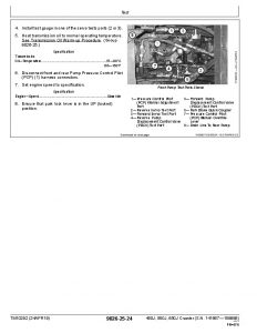
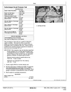
Intake Manifold Pressure Test—Turbocharger Boost…482
Section 9015: Electrical System…486
Group 05: System Information…486
Electrical Diagram Information…493
Group 10: System Diagrams…486
Fuse and Relay Specifications…504
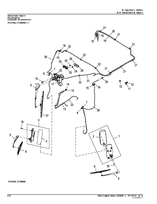
System Functional Schematic, Wiring Diagram, and Component Location Legend…511
System Functional Schematic and Section Legend…518
Power and Ground Cables (W1) Component Location…529
Cab Roof Harness (W4) Component Location…530
Cab Roof Harness (W4) Wiring Diagram…533
Main Cab/Canopy Harness (W5) Component Location…540
Main Cab/Canopy Harness (W5) Wiring Diagram…543
Engine Harness (W6) Component Location…557
Engine Harness (W6) Wiring Diagram…560
Transmission Harness (W7) Component Location…564
Transmission Harness (W7) Wiring Diagram…568
A/C Harness (W8) Component Location…571
A/C Harness (W8) Wiring Diagram…573
Radio Harness (W9) Component Location…574
Radio Harness (W9) Wiring Diagram…575
Canopy Auxiliary Light Harness (W11) Component Location…576
Canopy Auxiliary Light Harness (W11) Wiring Diagram…577
Grill Harness (W13) Component Location…578
Grill Harness (W13) Wiring Diagram…579
Integrated Grade Control (IGC) Machine Harness (W21) Component Location—If Equipped…580
Integrated Grade Control (IGC) Machine Harness (W21) Wiring Diagram—If Equipped…582
Integrated Grade Control (IGC) Cab Harness (W22) Component Location—If Equipped…583
Integrated Grade Control (IGC) Cab Harness (W22) Wiring Diagram—If Equipped…585
Charge Pressure Sensor Harness (W25) Wiring Diagram (S.N. 173345— )…587
JDLink™ System Harnesses Component Location—MIG/GTT…588
JDLink™ System Harnesses Component Location—MTG/SAT…589
JDLink™ System Wiring Diagrams—MIG/GTT…591
JDLink™ Ground Harness (W32) Wiring Diagram—If Equipped…594
JDLink™ System Wiring Diagrams—MTG/SAT…595
Group 15: Sub-System Diagnostics…487
Starting and Charging Circuit Theory of Operation…601
Controller Area Network (CAN) Circuit Theory of Operation…603
Engine Control Unit (ECU) Circuit Theory of Operation…605
Standard Display Monitor (SDM) Circuit Theory of Operation…611
Transmission Control Unit (TCU) Circuit Theory of Operation…614
Integrated Grade Control (IGC) Circuit Theory of Operation—If Equipped…619
JDLink™ Circuit Theory of Operation—If Equipped…624
Group 16: Monitor Operation…487
Standard Display Monitor (SDM) Menu Structure—Service Mode…633
Standard Display Monitor (SDM)—Change Units…639
Standard Display Monitor (SDM)—Hide/Unhide Main Menu…640
Standard Display Monitor (SDM)—Setting Hour Meter…642
Group 20: References…487
Service ADVISOR™ Diagnostic Application…645
Service ADVISOR™ Connection Procedure…646
Reading Diagnostic Trouble Codes with Service ADVISOR™ Diagnostic Application…649
JDLink™ System Identification…652
JDLink™ Connection Procedure—If Equipped…655
Alternator Test…657
CAN Circuit Test…659
Electrical Component Specifications…664
Transmission Control Unit (TCU) Calibration…667
Integrated Grade Control (IGC) Checks—If Equipped…487
Integrated Grade Control (IGC) Diagnose Malfunctions—If Equipped…487
Decelerator/Brake Pedal Adjustment…703
Engine Speed Control Remove and Install…705
Rotary Sensor Remove and Install…707
Transmission Control Lever (TCL) Adjustment…709
Replace Weather Pack™ Connector…713
Install Weather Pack™ Contact…715
Replace DEUTSCH® Connectors…717
Replace Rectangular or Triangular Connectors…719
Install DEUTSCH® Contact…721
Repair 32 and 48 Way CINCH™ Connectors…723
Replace (Pull Type) Metri-Pack™ Connectors…727
Replace (Push Type) Metri-Pack™ Connectors…729
Section 9025: Hydraulic System…730
Group 05: Theory of Operation…730
Hydraulic System Operation…733
Hydraulic Pump Operation…734
Hydraulic Pump and Reservoir Operation…735
Hydraulic Filter Operation…737
Hydraulic Control Valve Operation…741
Hydraulic System Relief Valve Operation…742
Inlet Valve Operation…744
Auxiliary Valve Operation…745
Blade Lift Valve Operation…747
Blade Angle Valve Operation…749
Blade Tilt Valve Operation…751
Outlet Valve Cover Operation…753
Hydraulic Control Valve Operation—IGC…754
Hydraulic Cylinder Operation…758
Group 15: Diagnostic Information…730
Hydraulic System Schematic…761
Hydraulic System Schematic—IGC…763
Hydraulic Component Location…765
Hydraulic Component Location—IGC…770
Ripper Hydraulic Component Location…773
Hydraulic System Diagnose Malfunctions…730
Hydraulic System Diagnose Malfunctions—IGC…730
Group 20: Adjustments…730
Hydraulic Control Lever Linkage Adjustment…810
Auxiliary Lever Linkage Adjustment…812
Blade Pitch Linkage Adjustment…814
Group 25: Tests…730
Hydraulic Oil Warm-Up Procedure…816
Hydraulic Oil Sampling Procedure—If Equipped…817
Hydraulic Pump Flow Test…818
Hydraulic System Relief Valve Test…821
Hydraulic System Relief Valve Test—IGC…824
Circuit Relief Valve Test—With Remote Pump…826
Hydraulic Pump Cycle Time Test…829
Lift Cylinder Drift Test…830
Cylinder Leakage Test…832
Oil Clean-up Procedure…834
Section 9026: Hydrostatic System…845
Group 05: Theory of Operation…842
Hydrostatic System…845
Transmission Control Circuit Operation (Flow Chart)…846
Charge Pump Operation…848
Hydrostatic Filter Operation…849
Neutral Charge Relief Valve Operation…852
Park Brake Operation…854
Multi-Function Valve Operation…857
Oil Cooler Bypass Valve Operation…859
Pump Pressure Control Pilot (PCP) Operation…861
Pump Displacement Control Valve (PDCV) Operation…863
Hydrostatic Pump Operation…865
Flushing Valve and Operating Charge Relief Valve Operation…867
Hydrostatic Motor Operation…869
Group 15: Diagnostic Information…842
Hydrostatic Schematic—Neutral (Park Brake ON)…872
Hydrostatic System Component Location…873
Hydrostatic System Diagram—Park Brake On (Neutral)…875
Hydrostatic System Diagram—Forward (Slow Speed)…877
Hydrostatic System Diagram—Reverse (Fast Speed)…879
Overheating Malfunctions…842
High/Low Charge Pressure Malfunctions…842
Mistrack/Index Malfunctions…842
Machine Full Speed Malfunctions…842
Low Power Malfunctions…842
Track Malfunctions…842
TCU Calibration Malfunctions…842
Group 25: Test…842
JT05800 Digital Thermometer Installation…928
Digital Pressure And Temperature Analyzer Installation…929
Hydraulic Oil Cleanup Procedure…930
Ultra Clean® Hand Launcher…931
Transmission Oil Warmup Procedure…932
Hydrostatic Oil Sampling Procedure—If Equipped…934
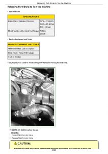
Releasing Park Brake to Tow the Machine…935
Hydrostatic Pump and Motor Initial Start-Up Procedure…939
Hydrostatic Pump Flushing Procedure…942
Pressure Control Pilot (PCP) Manual Override Test…944
Pressure Control Pilot (PCP) Test…946
Pressure Control Pilot (PCP) Internal Adjustment…950
Multi-Function Relief Valve Test…953
Transmission Efficiency Test…958
Neutral Charge Relief and Operating Charge Relief Pressure Test…963
Pump Displacement Control Valve (PDCV) Neutral (Null) Adjustment…966
Pump Servo Pressure Test…970
Hydrostatic Motor Min./Max. Angle Servo Piston Pressure Test…973
Hydrostatic Motor Min. Angle Stop Adjustment…975
Charge Pump Flow Test…979
Cooler Bypass Valve Test…982
Section 9031: Heating and Air Conditioning…985
Group 05: Theory of Operation…985
Air Conditioning System Cycle Of Operation…988
Group 15: Diagnostic Information…985
Air Conditioning System Diagnose Malfunctions…985
Heater System Diagnose Malfunctions…985
Group 25: Test…985
Proper Refrigerant Handling…1019
R134a Refrigerant Cautions…1020
R134a Oil Charge Capacity…1021
R134a Refrigerant Charge Capacity…1022
Refrigerant Hoses And Tubing Inspection…1023
Operating Pressure Diagnostic Chart…1024
Air Conditioner High/Low Pressure (Binary) Switch Test…1029
Freeze Control Switch Test…1031
Leak Testing…1032

John Deere Crawler Dozer 450J, 550J, 650J Diagnostics Technical Manual (TM10721)


INSTANT DOWNLOAD


Posted on

John Deere Crawler Dozers 450J, 550J, 650J Diagnostic Technical Manual (TM10292)


INSTANT DOWNLOAD


Complete operation & test technical manual with Electrical Wiring Diagrams for John Deere Crawler Dozers 450J, 550J, 650J (S.N. 141667—159986), with workshop diagnostic information to maintain, test, and service like professional mechanics.

John Deere Crawler Dozers 450J, 550J, 650J workshop Operation and Test manual includes:
* Numbered table of contents easy to use so that you can find the information you need fast.
* Detailed sub-steps expand on repair procedure information
* Numbered instructions guide you through every repair procedure step by step.
* Troubleshooting and electrical service procedures are combined with detailed wiring diagrams for ease of use.
* Notes, cautions and warnings throughout each chapter pinpoint critical information.
* Bold figure number help you quickly match illustrations with instructions.
* Detailed illustrations, drawings and photos guide you through every procedure.
* Enlarged inset helps you identify and examine parts in detail.

TM10292 – John Deere 450G, 455G, 550G, 555G, 650G Crawler Dozer Technical Manual (Operation and Test).PDF

Total Pages: 1,020 pages
File Format: PDF (PC/Mac/Android/Kindle/iPhone/iPad; bookmarked, ToC, Searchable, Printable)
Language: English

MAIN SECTIONS
Foreword
Technical Information Feedback Form
General Information
Safety
Diagnostic Trouble Codes
Standard Display Monitor (SDM) Diagnostic Trouble Codes
Engine Control Unit (ECU) Diagnostic Trouble Codes
Transmission Control Unit (TCU) Diagnostic Trouble Codes
Electrohydraulic Controller (EHC) Diagnostic Trouble Codes
Blade Control Joystick (BCJ) Diagnostic Trouble Codes
Operational Checkout Procedure
System Operational Checks
Engine
Theory Of Operation
System Diagnostic Information
Tests
Electrical System
System Information
System Diagrams
Sub-System Diagnostics
References
Hydraulic System
Theory of Operation
Diagnostic Information
Adjustments
Tests
Hydrostatic System
Theory of Operation
Diagnostic Information
Test
Heating and Air Conditioning
Theory of Operation
Diagnostic Information
Test
tm10292 – 450J, 550J, 650J Crawler Dozer (SN 141667-159986)
Table of Contents
Foreword
Technical Information Feedback Form
Section 9000: General Information
Group 01: Safety
Recognize Safety Information
Follow Safety Instructions
Operate Only If Qualified
Wear Protective Equipment
Avoid Unauthorized Machine Modifications
Inspect Machine
Stay Clear of Moving Parts
Avoid High-Pressure Fluids
Avoid High-Pressure Oil
Beware of Exhaust Fumes
Prevent Fires
Prevent Battery Explosions
Handle Chemical Products Safely
Dispose of Waste Properly
Prepare for Emergencies
Add Cab Guarding For Special Uses
Start Only From Operator’s Seat
Prevent Unintended Machine Movement
Avoid Work Site Hazards
Keep Riders Off Machine
Avoid Backover Accidents
Avoid Machine Tip Over
Prevent Unintended Detonation of Explosive Devices
Park And Prepare For Service Safely
Service Cooling System Safely
Remove Paint Before Welding or Heating
Make Welding Repairs Safely
Drive Metal Pins Safely
Section 9001: Diagnostic Trouble Codes
Group 10: Standard Display Monitor (SDM) Diagnostic Trouble Codes
Standard Display Monitor (SDM) Diagnostic Trouble Codes
000096.03 – Fuel Level Sender Open or Short
000096.04 – Fuel Level Sender Short to Gnd
000107.03 – Eng Air Filter Short to Power
000107.04 – Eng Air Filter Restricted
000177.03 – Trans Oil Temp Short to Power
000177.04 – Trans Oil Temp Short to Gnd
000177.16 – Transmission Oil Temperature High
000609.09 – CAN Comm No TCU Msg
001638.00 – Hydraulic Oil High Temp
001638.03 – Hydraulic Oil Temp Short to Power
001638.04 – Hydraulic Oil Temp Short to Gnd
001713.31 – Hydraulic Oil Filter Restricted
002000.09 – CAN Comm No ECU Config
003156.09 – CAN Blade Mode Missing From EHC
003359.31 – Trans Oil Filter Restricted
Group 20: Engine Control Unit (ECU) Diagnostic Trouble Codes
Engine Control Unit (ECU) Diagnostic Trouble Codes
000091.09 – CAN Throttle Missing from TCU
Group 30: Transmission Control Unit (TCU) Diagnostic Trouble Codes
Transmission Control Unit (TCU) Diagnostic Trouble Codes
!CAL – Calibrate TCU
F311 – Sensor Supply Short to Gnd
F314 – Sensor Supply Short to Power
F321 – TCU System Volts Too Low
F324 – TCU System Volts Too High
F330 – FNR Sensor Open or Short
F331 – FNR Input Less Than Min Cal
F334 – FNR Input Greater Than Max Cal
F335 – FNR Sensor Short to Power
F336 – FNR Sensor Min Cal Too Low
F337 – FNR Sensor Min Cal Too High
F338 – FNR Sensor Max Cal Too Low
F339 – FNR Sensor Max Cal Too High
F340 – Steer Sensor Open or Short
F341 – Steer Sensor Input Less Than Min Cal
F344 – Steer Sensor Input Greater Than Max Cal
F345 – Steer Sensor Short to Power
F346 – Steer Sensor Min Cal Too Low
F347 – Steer Sensor Min Cal Too High
F348 – Steer Sensor Max Cal Too Low
F349 – Steer Sensor Max Cal Too High
F350 – Decelerator Sensor Open or Short
F351 – Decelerator Sensor Input Less Than Min Cal
F354 – Decelerator Sensor Input Greater Than Max Cal
F355 – Decelerator Sensor Short to Power
F356 – Decelerator Sensor Min Cal Too Low
F357 – Decelerator Sensor Min Cal Too High
F358 – Decelerator Sensor Max Cal Too Low
F359 – Decelerator Sensor Max Cal Too High
F370 – Left Speed Sensor Short
F372 – Left Speed Sensor Open
F373 – Left Speed Sensor No Response
F375 – Left Speed Sensor Short to Power
F380 – Right Speed Sensor Short
F382 – Right Speed Sensor Signal Open
F383 – Right Speed Sensor No Response
F385 – Right Speed Sensor Short to Power
F393 – CAN Comm No Engine Speed
F3A0 – Left Fwd Pump Coil Short
F3A5 – Left Fwd Pump Coil Open
F3A6 – Left Fwd Pump Thresh Cal Low
F3A7 – Left Fwd Pump Thresh Cal High
F3A8 – Left Fwd Pump Max Spd Cal Low
F3A9 – Left Fwd Pump Max Spd Cal High
F3B3 – Brake Solenoid No Response
F3B8 – Decelerator Sensor Brake Cal Too Low
F3B9 – Decelerator Sensor Brake Cal Too High
F3C0 – Right Fwd Pump Coil Short
F3C5 – Right Fwd Pump Coil Open
F3C6 – Right Fwd Pump Thresh Cal Low
F3C7 – Right Fwd Pump Thresh Cal High
F3C8 – Right Fwd Pump Max Spd Cal Low
F3C9 – Right Fwd Pump Max Spd Cal High
F3D0 – Right Rev Pump Coil Short
F3D5 – Right Rev Pump Coil Open
F3D6 – Right Rev Pump Thresh Cal Low
F3D7 – Right Rev Pump Thresh Cal High
F3D8 – Right Rev Pump Max Spd Cal Low
F3D9 – Right Rev Pump Max Spd Cal High
F3E0 – Left Rev Pump Coil Short
F3E5 – Left Rev Pump Coil Open
F3E6 – Left Rev Pump Thresh Cal Low
F3E7 – Left Rev Pump Thresh Cal High
F3E8 – Left Rev Pump Max Spd Cal Low
F3E9 – Left Rev Pump Max Spd Cal High
F3H1 – FNR Neut Switch Short Circuit
F3H4 – FNR Neut Switch Open Circuit
F3H6 – FNR Neut Switch Min Cal Too Low
F3H7 – FNR Neut Switch Min Cal Too High
F3H8 – FNR Neut Switch Max Cal Too Low
F3H9 – FNR Neut Switch Max Cal Too High
F3K3 – Right Motor Sol No Response
F3K8 – Right Motor Max Cal Too Low
F3K9 – Right Motor Max Cal Too High
F3L3 – Left Motor Sol No Response
F3L8 – Left Motor Max Cal Too Low
F3L9 – Left Motor Max Cal Too High
F3P0 – Park Lock Lever Inputs Both On
F3P5 – Park Lock Lever Inputs Both Off
F3T0 – Speed Buttons Open or Short
F3T1 – Speed Buttons Input Less Than Min Cal
F3T4 – Speed Buttons Input Greater Than Max Cal
F3T5 – Speed Buttons Short to Power
F3T6 – Speed Buttons Min Cal Too Low
F3T7 – Speed Buttons Min Cal Too High
F3T8 – Speed Buttons Max Cal Too Low
F3T9 – Speed Buttons Max Cal Too High
F3U0 – Throttle Sensor Open or Short
F3U1 – Throttle Sensor Input Less Than Min Cal
F3U4 – Throttle Sensor Input Greater Than Max Cal
F3U5 – Throttle Sensor Short to Power
F3U6 – Throttle Sensor Min Cal Too Low
F3U7 – Throttle Sensor Min Cal Too High
F3U8 – Throttle Sensor Max Cal Too Low
F3U9 – Throttle Sensor Max Cal Too High
F3X0 – Charge Pressure Open or Short
F3X1 – Charge Pressure Low
F3X4 – Charge Pressure High
F3X5 – Charge Pressure Short to Power
F3Y4 – Transmission Overtemp
Group 40: Electrohydraulic Controller (EHC) Diagnostic Trouble Codes
Electrohydraulic Controller (EHC) Diagnostic Trouble Codes
000158.03 – EHC System Volts Too High
000158.04 – EHC System Volts Too Low
000620.03 – Sensor Short to Power
000620.04 – Sensor Short to GND
001903.00 – Aux 1 PVE Open Circuit
001903.01 – Aux 1 PVE Low or Open Circuit
001903.03 – Aux 1 PVE Short to Power
001903.04 – Aux 1 PVE Short to GND
001903.31 – Aux 1 PVE Spool Pos Error
001915.00 – Aux 2 PVE Open Circuit
001915.01 – Aux 2 PVE Low or Open Circuit
001915.03 – Aux 2 PVE Short to Power
001915.04 – Aux 2 PVE Short to GND
001915.31 – Aux 2 PVE Spool Pos Error
002697.09 – CAN Joystick Pos Missing From BCJ
002712.00 – Hyd Enable Sw Inputs Both On
002712.01 – Hyd Enable Sw Inputs Both Off
003157.03 – Incr / Decr Buttons Short to Power
003157.04 – Incr / Decr Buttons Open or Short
003157.31 – Incr / Decr Buttons Invalid Output
522442.31 – Blade Buttons Invalid Output
523779.00 – Blade Rotate Current Above Max
523779.01 – Blade Rotate Current Below Min
523780.00 – Tilt PVE Open Circuit
523780.01 – Tilt PVE Low or Open Circuit
523780.03 – Tilt PVE Short to Power
523780.04 – Tilt PVE Short to GND
523780.31 – Tilt PVE Spool Pos Error
523781.00 – Height PVE Open Circuit
523781.01 – Height PVE Low or Open Circuit
523781.03 – Height PVE Short to Power
523781.04 – Height PVE Short to GND
523781.31 – Height PVE Spool Pos Error
524059.00 – Aux 2 Jstk Sensor 2 Volts High
524059.01 – Aux 2 Jstk Sensor 2 Volts Low
524059.03 – Aux 2 Jstk Sensor 2 Short to Power
524059.04 – Aux 2 Jstk Sensor 2 Short to GND
524059.31 – Aux 2 Jstk Sensor 2 Invalid Output
524062.00 – Aux 1 Jstk Sensor 2 Volts High
524062.01 – Aux 1 Jstk Sensor 2 Volts Low
524062.03 – Aux 1 Jstk Sensor 2 Short to Power
524062.04 – Aux 1 Jstk Sensor 2 Short to GND
524062.31 – Aux 1 Jstk Sensor 2 Invalid Output
524085.00 – Aux 2 Jstk Sensor 1 Volts High
524085.01 – Aux 2 Jstk Sensor 1 Volts Low
524085.03 – Aux 2 Jstk Sensor 1 Short to Power
524085.04 – Aux 2 Jstk Sensor 1 Short to GND
524085.14 – Aux 2 Jstk Sensor Mismatch
524085.31 – Aux 2 Jstk Sensor 1 Invalid Output
524086.00 – Aux 1 Jstk Sensor 1 Volts High
524086.01 – Aux 1 Jstk Sensor 1 Volts Low
524086.03 – Aux 1 Jstk Sensor 1 Short to Power
524086.04 – Aux 1 Jstk Sensor 1 Short to GND
524086.14 – Aux 1 Jstk Sensor Mismatch
524086.31 – Aux 1 Jstk Sensor 1 Invalid Output
Group 50: Blade Control Joystick (BCJ) Diagnostic Trouble Codes
Blade Control Joystick (BCJ) Diagnostic Trouble Codes (DTC)
002697.03 – X-Axis Sensor Out of Range High
002697.04 – X-Axis Sensor Out of Range Low
002697.12 – X-Axis Joystick Internal Failure
002697.13 – X-Axis Joystick Setup Failure
002697.14 – X-Axis Joystick Sensor Failure
002698.03 – Y-Axis Sensor Out of Range High
002698.04 – Y-Axis Sensor Out of Range Low
002698.12 – Y-Axis Joystick Internal Failure
002698.13 – Y-Axis Joystick Setup Failure
002698.14 – Y-Axis Joystick Sensor Failure
Section 9005: Operational Checkout Procedure
Group 10: System Operational Checks
Operational Checkout
Section 9010: Engine
Group 05: Theory Of Operation
POWERTECH POWERTECH is a trademark of Deere & Company 4.5 L (4045) John Deere Engine
Cold Weather Starting Aid Operation
Group 15: System Diagnostic Information
Diagnose Engine Malfunctions
Group 25: Tests
Slow and Fast Idle Test
Fuel System Test
Intake Manifold Pressure Test—Turbocharger Boost
Section 9015: Electrical System
Group 05: System Information
Electrical Diagram Information
Group 10: System Diagrams
Fuse and Relay Specifications (S.N. 141667—153832)
Fuse and Relay Specifications (S.N. 153833— )
System Functional Schematic, Wiring Diagram, and Component Location Legend
System Functional Schematic and Schematic Legend
JDLink™ System Functional Schematic—MIG/GTT
JDLink™ System Functional Schematic—MTG/SAT
Canopy Harness (W4) Component Location
Canopy Harness (W4) Wiring Diagram
Cab Harness (W5) Component Location
Cab Harness (W5) Wiring Diagram
Engine Harness (W6) Component Location
Engine Harness (W6) Wiring Diagram
Transmission Harness (W7) Component Location
Transmission Harness (W7) Wiring Diagram
A/C Harness (W8) Component Location
A/C Harness (W8) Wiring Diagram
Radio Harness (W9) Component Location
Radio Harness (W9) Wiring Diagram
Canopy Auxiliary Light Harness (W11) Component Location
Canopy Auxiliary Light Harness (W11) Wiring Diagram
Grill Harness (W13) Component Location
Grill Harness (W13) Wiring Diagram
Integrated Grade Control (IGC) Machine Harness (W21) Component Location—If Equipped
Integrated Grade Control (IGC) Machine Harness (W21) Wiring Diagram—If Equipped
Integrated Grade Control (IGC) Cab Harness (W22) Component Location—If Equipped
Integrated Grade Control (IGC) Cab Harness (W22) Wiring Diagram—If Equipped
JDLink™ System Harnesses Component Location—MIG/GTT
JDLink™ System Harnesses Component Location—MTG/SAT
JDLink™ System Wiring Diagrams—MIG/GTT
JDLink™ Ground Harness (W32) Wiring Diagram—If Equipped (S.N. 153833— )
JDLink™ System Wiring Diagrams—MTG/SAT
Group 15: Sub-System Diagnostics
Starting and Charging Circuit Theory of Operation
Controller Area Network (CAN) Circuit Theory of Operation
Engine Control Unit (ECU) Circuit Theory of Operation
Standard Display Monitor (SDM) Circuit Theory of Operation
Transmission Control Unit (TCU) Circuit Theory of Operation
Integrated Grade Control (IGC) Circuit Theory of Operation—If Equipped
Group 20: References
Diagnostic Trouble Codes (DTC) Quick Reference List
Service ADVISOR™ Diagnostic Application
Service ADVISOR™ Connection Procedure
Reading Diagnostic Trouble Codes with Service ADVISOR™ Diagnostic Application
JDLink™ System Identification
JDLink™ Connection Procedure—If Equipped
Alternator Test
CAN Circuit Test
Electrical Component Specifications
Transmission Control Unit (TCU) Calibration
Standard Display Monitor (SDM) Menu Structure—Service Mode
Standard Display Monitor (SDM)—Change Units
Standard Display Monitor (SDM)—Hide/Unhide Main Menu
Standard Display Monitor (SDM) Setting Hour Meter
Transmission Control Unit (TCU) Menu Structure
Integrated Grade Control (IGC) Checks—If Equipped
Integrated Grade Control (IGC) Diagnose Malfunctions—If Equipped
Decelerator/Brake Pedal Adjustment
Engine Speed Control Remove and Install
Rotary Sensor Remove and Install
Transmission Control Lever (TCL) Adjustment
Replace Weather Pack™ Connector
Install Weather Pack™ Contact
Replace DEUTSCH® Connectors
Replace Rectangular or Triangular Connectors
Install DEUTSCH® Contact
Repair 32 and 48 Way CINCH™ Connectors
Replace (Pull Type) Metri-Pack™ Connectors
Replace (Push Type) Metri-Pack™ Connectors
Section 9025: Hydraulic System
Group 05: Theory of Operation
Hydraulic System Operation
Hydraulic Pump Operation
Hydraulic Pump and Reservoir Operation
Hydraulic Filter Operation—Normal
Hydraulic Filter Operation Continued—Restricted
Hydraulic Control Valve Operation
Hydraulic System Relief Valve Operation
Inlet Valve Operation
Auxiliary Valve Operation
Blade Lift Valve Operation
Blade Angle Valve Operation
Blade Tilt Valve Operation
Outlet Valve Cover Operation
Hydraulic Control Valve Operation—IGC
Hydraulic Cylinder Operation
Group 15: Diagnostic Information
Hydraulic System Schematic
Hydraulic System Schematic—IGC
Hydraulic Component Location
Hydraulic Component Location—IGC
Ripper Hydraulic Component Location
Hydraulic System Diagnose Malfunctions
Hydraulic System Diagnose Malfunctions—IGC
Group 20: Adjustments
Hydraulic Control Lever Linkage Adjustment
Auxiliary Lever Linkage Adjustment
Blade Pitch Linkage Adjustment
Group 25: Tests
Hydraulic Oil Warm-Up Procedure
Hydraulic Pump Flow Test
Hydraulic System Relief Valve Test
Hydraulic System Relief Valve Test—IGC
Circuit Relief Valve Test—With Remote Pump
Hydraulic Pump Cycle Time Test
Lift Cylinder Drift Test
Cylinder Leakage Test
Oil Clean-up Procedure
Section 9026: Hydrostatic System
Group 05: Theory of Operation
Hydrostatic System
Transmission Control Circuit—Flow Chart
Charge Pump Operation
Hydrostatic Filter Operation
Neutral Charge Relief Valve Operation
Park Brake Operation
Multi-Function Valve Operation
Oil Cooler Bypass Valve Operation
Pump Pressure Control Pilot (PCP) Operation
Pump Displacement Control Valve (PDCV) Operation
Hydrostatic Pump Operation
Flushing Valve and Operating Charge Relief Valve Operation
Hydrostatic Motor Operation
Group 15: Diagnostic Information
Hydrostatic Schematic—Neutral (Park Brake ON)
Hydrostatic System Component Location
Hydrostatic System Diagram—Park Brake On (Neutral)
Hydrostatic System Diagram—Forward (Slow Speed)
Hydrostatic System Diagram—Reverse (Fast Speed)
Overheating Malfunctions
High/Low Charge Pressure Malfunctions
Mistrack/Index Malfunctions
Machine Full Speed Malfunctions
Low Power Malfunctions
Track Malfunctions
TCU Calibration Malfunctions
Group 25: Test
JT05800 Digital Thermometer Installation
Digital Pressure And Temperature Analyzer Installation
Hydraulic Oil Cleanup Procedure
Ultra Clean® Hand Launcher
Transmission Oil Warm-up Procedure
Releasing Park Brake to Tow the Machine
Hydrostatic Pump and Motor Initial Start-Up Procedure
Hydrostatic Pump Flushing Procedure
Pressure Control Pilot (PCP) Manual Override Test
Pressure Control Pilot (PCP) Test
Pressure Control Pilot (PCP) Internal Adjustment
Multi-Function Relief Valve Test
Transmission Efficiency Test
Neutral Charge Relief and Operating Charge Relief Pressure Test
Pump Displacement Control Valve (PDCV) Neutral (Null) Adjustment
Pump Servo Pressure Test
Hydrostatic Motor Min./Max. Angle Servo Piston Pressure Test
Hydrostatic Motor Min. Angle Stop Adjustment
Charge Pump Flow Test
Cooler Bypass Valve Test
Section 9031: Heating and Air Conditioning
Group 05: Theory of Operation
Air Conditioner System Cycle Of Operation
Group 15: Diagnostic Information
Air Conditioner System Diagnose Malfunctions
Heater System Diagnose Malfunctions
Group 25: Test
Proper Refrigerant Handling
R134a Refrigerant Cautions
R134a Oil Charge Capacity
R134a Refrigerant Charge Capacity
Refrigerant Hoses And Tubing Inspection
Operating Pressure Diagnostic Chart
Air Conditioner High/Low Pressure (Binary) Switch Test
Freeze Control Switch Test
Leak Testing

John Deere Crawler Dozers 450J, 550J, 650J Diagnostic Technical Manual (TM10292)


INSTANT DOWNLOAD


Posted on

John Deere Crawler Dozers 450J, 550J, 650J Technical Repair Manual (TM2258)


INSTANT DOWNLOAD


Complete service repair manual for John Deere Crawler Dozers 450J, 550J, 650J (S.N.before 141666), with workshop information to maintain, repair, and service like professional mechanics.

John Deere Crawler Dozers 450J, 550J, 650J workshop service repair manual includes:
* Numbered table of contents easy to use so that you can find the information you need fast.
* Detailed sub-steps expand on repair procedure information
* Numbered instructions guide you through every repair procedure step by step.
* Notes, cautions and warnings throughout each chapter pinpoint critical information.
* Bold figure number help you quickly match illustrations with instructions.
* Detailed illustrations, drawings and photos guide you through every procedure.
* Enlarged inset helps you identify and examine parts in detail.

TM2258 (English) – John Deere 450G, 455G, 550G, 555G, 650G Crawler Dozer Technical Manual (Repair).PDF
tm2995 (French) – Bouteurs chenillés 450J, 550J, 650J ( —141666)
tm9008 (Spanish) – Bulldozer sobre orugas 450J, 550J, 650J ( —141666)

Total Pages: 680 pages
File Format: PDF (bookmarked, ToC, Searchable, Printable)
Language: English etc.

Product Lines: Crawler Dozers
Publication Type: Repair Manuals
Associated Models: 450J, 550J, 650J
Serial: DOZER XXXXXX-159986

See also:
omt204685 English – 450J, 550J, and 650J Crawler Dozer Operator’s Manual
omt204707 Spanish – Bulldozer sobre orugas 450J, 550J, y 650J
omt204709 French – Bouteurs chenillés 450J, 550J et 650J

omt302214 English – Crawler Dozer 450J (S.N. 216243— ) Operator’s Manual
omt302407 Spanish – Bulldozer sobre orugas 450J (216243— )
omt302416 French – Bouteur chenillé 450J (216243— )

ctm104 English – 4.5L AND 6.8L DIESEL ENGINES (BASE ENGINE) -: (WORLDWIDE EDITION) CTM
ctm166 English – 4000S Winches CTM
ctm310 English – Super Caddy Oil Cleanup Procedure CTM
ctm331 English – PowerTech™ 4.5L and 6.8L Diesel EnginesLevel 12 ElectronicFuel System WithStanadyne DE10 Pump -: (Worldwide Edition) CTM
ctm502 English – 4045-6068 Diesel Engine — Level 16 ECU -: (Worldwide Edition) CTM

MAIN SECTIONS
Foreword
General Information
Safety
Torque Values
Tracks
Track System
Axles and Suspension Systems
Drive Axle Housing and Support
Axle Shaft, Bearings, and Reduction Gear
Transmission
Removal and Installation
Controls Linkage
Hydrostatic System
Engine
Removal and Installation
Engine Auxiliary Systems
Cold Weather Starting Aids
Radiator and Fan Shroud
Engine Speed Control
Intake System
External Exhaust System
Mounting Frame
External Fuel Supply System
Dampener Drive
Elements
Park Brake
Removal and Installation
Control Linkage
Hydraulic System
Operator`s Station
Removal and Installation
Operator`s Enclosure
Seat and Seat Belt
Heating and Air Conditioning
Sheet Metal and Styling
Hood and Engine Enclosure
Grille and Grille Housing
Main Hydraulic System
Hydraulic System
Bulldozer
Blades
Control Linkage
Frames
Hydraulic System
Dealer Fabricated Tools
tm2258 – 450J, 550J, 650J Crawler Dozer (S.N. —141666)
Table of Contents
Foreword
HELP!! HELP!! HELP!! HELP!!
Section 00: General Information
Group 01: Safety
Recognize Safety Information
Follow Safety Instructions
Operate Only If Qualified
Wear Protective Equipment
Avoid Unauthorized Machine Modifications
Inspect Machine
Stay Clear of Moving Parts
Avoid High-Pressure Fluids
Beware of Exhaust Fumes
Prevent Fires
Prevent Battery Explosions
Handle Chemical Products Safely
Dispose of Waste Properly
Prepare for Emergencies
Add Cab Guarding For Special Uses
Start Only From Operator’s Seat
Prevent Unintended Machine Movement
Avoid Work Site Hazards
Keep Riders Off Machine
Avoid Backover Accidents
Avoid Machine Tip Over
Park And Prepare For Service Safely
Service Cooling System Safely
Remove Paint Before Welding or Heating
Make Welding Repairs Safely
Drive Metal Pins Safely
Group 03: Torque Values
Metric Bolt and Cap Screw Torque Values
Additional Metric Cap Screw Torque Values
Unified Inch Bolt and Cap Screw Torque Values
Service Recommendations for 37° Flare and 30° Cone Seat Connectors
Service Recommendations for O-Ring Boss Fittings
O-Ring Boss Fittings In Aluminum Housing Service Recommendations—Excavators
Service Recommendations for Flared Connections—Straight or Tapered Threads
Service Recommendations For Flat Face O-Ring Seal Fittings
O-Ring Face Seal Fittings With SAE Inch Hex Nut And Stud End For High Pressure Service Recommendations
O-Ring Face Seal Fittings With Metric Hex Nut And Stud End For Standard Pressure Service Recommendations
O-Ring Face Seal Fittings With Metric Hex Nut And Stud End For High Pressure Service Recommendations
Service Recommendations for Metric Series Four Bolt Flange Fitting
Service Recommendations For Inch Series Four Bolt Flange Fittings
Inch Series Four Bolt Flange Fitting For High Pressure Service Recommendations
Service Recommendations For Non-Restricted Banjo (Adjustable) Fittings
Service Recommendations For O-Ring Boss Fittings With Shoulder
Metric 24° O-Ring Seal DIN 20078 Service Recommendations
Section 01: Tracks
Group 0130: Track System
Rock Guards and Chain Guides Remove and Install
Carrier Roller Remove and Install
Carrier Roller Disassemble and Assemble
Metal Face Seals Inspection
Track Roller Remove and Install
Track Roller Disassemble and Assemble
Track Roller Leakage Test
Track Shoe Remove and Install
Sealed Track Chain Removal
Sealed Track Chain Disassemble and Assemble
Sealed Track Chain Installation
Lubricated Track Chain (Saw Tooth Master Split Link) Remove and Install
Lubricated Track Chain Disassembly (Turn Bushings and Lubricate Chain)
Lubricated Track Chain Assembly (Turn Bushings and Lubricate Chain)
Lubricated Track Chain Disassemble and Assemble (Turn Pins and Not Lubricate)
Front Idler Remove and Install
Front Idler Disassemble, Inspect, and Assemble
Front Idler Adjustment
Front Idler Oil Level Check
Track Tension Adjuster Remove and Disassemble
Track Tension Adjuster Assemble and Install
Track Idler Recoil Spring Remove and Install
Track Idler Recoil Spring Disassemble and Assemble
Sprocket Remove and Install
Track Frame Remove and Install
Track Frame Disassemble and Assemble
Frame Wear Strips Remove and Install
Section 02: Axles and Suspension Systems
Group 0201: Drive Axle Housing and Support
Final Drive Remove and Install
Group 0250: Axle Shaft, Bearings, and Reduction Gear
Final Drive Disassemble and Assemble
Section 03: Transmission
Group 0300: Removal and Installation
Hydrostatic Pump Remove and Install
Hydrostatic Motor Remove and Install
Group 0315: Controls Linkage
Transmission Control Lever (TCL) Remove and Install
Transmission Control Lever (TCL) Disassemble and Assemble (S.N. —130885)
Group 0360: Hydrostatic System
Hydrostatic Pumps Disassemble
Hydrostatic Charge Pump Disassemble and Assemble
Pump Displacement Control Valve (PDCV) Disassemble and Assemble
Multi-Function Valve Disassemble and Assemble
Neutral Charge Relief Valve Disassemble and Assemble
Hydrostatic Pump Assemble
Hydrostatic Motor Disassemble
Hydrostatic Motor Assemble
Oil Cooler Thermal Bypass Valve Remove and Install
Hydrostatic Filter Remove and Install
Hydrostatic Filter Disassemble and Assemble
Hydrostatic Reservoir Remove and Install
Section 04: Engine
Group 0400: Removal and Installation
Engine Remove and Install
Section 05: Engine Auxiliary Systems
Group 0505: Cold Weather Starting Aids
Engine Coolant Heater Remove and Install
Start Aid Remove and Install
Starting Aid Solenoid Remove and Install
Group 0510: Radiator and Fan Shroud
Fan Blade and Shroud Remove and Install (450J, 550J)
Fan Blade and Shroud Remove and Install (650J)
Cooling Package Remove and Install (450J, 550J)
Cooling Package Remove and Install (650J)
Sand Shield Remove and Install
Group 0515: Engine Speed Control
Decelerator/Brake Pedal Remove and Install
Decelerator/Brake Pedal Disassemble and Assemble
Group 0520: Intake System
Air Cleaner Remove and Install 550J and 650J
Group 0530: External Exhaust System
Muffler Without Turbocharger Remove and Install
Muffler With Turbocharger Remove and Install
Group 0540: Mounting Frame
Engine and Power Train Mounting
Group 0560: External Fuel Supply System
Fuel Tank Remove and Install
Section 07: Dampener Drive
Group 0752: Elements
Dampener Drive Remove and Install
Section 11: Park Brake
Group 1100: Removal and Installation
Park Brake Valve Remove and Install
Park Brake Remove and Install
Group 1115: Control Linkage
Park Lock Linkage Remove and Install
Park Lock Linkage Disassemble and Assemble
Group 1160: Hydraulic System
Park Brake Valve Disassemble and Assemble
Park Brake Disassemble and Assemble
Section 18: Operator’s Station
Group 1800: Removal and Installation
Cab or ROPS Remove and Install
Group 1810: Operator’s Enclosure
Slide Glass Remove and Install
Stationary Glass Remove and Install
Sliding Window Remove and Install
Front Window Wiper Remove and Install
Door Window Wipers Remove and Install
Rear Window Wiper Remove and Install
Window Washer Pumps Remove and Install
Group 1821: Seat and Seat Belt
Standard Seat Remove and Install (Old)
Deluxe Seat Remove and Install
Air Suspension Seat Remove and Install
Group 1830: Heating and Air Conditioning
R134a Refrigerant Cautions
R134a Compressor Oil Charge Check
R134a Compressor Oil Removal
R134a Component Oil Charge
Leakage Testing
R134a Refrigerant Recovery, Recycling and Charging Station Installation Procedure
Recover R134a System
Evacuate R134a System
Charge R134a System
Air Conditioner System Cleaning Procedures
Purge R134a System
Flush R134a System
Evaporator or Heater Core Remove and Install
Expansion Valve Remove and Install
A/C Freeze Switch Remove and Install
Upper Cab Heater Blower Motor and Heater Blower Resistor Remove and Install
Cab Upper Heater Disassemble and Assemble
Cab or ROPS Under Seat Heater Disassemble and Assemble
Receiver-Dryer Remove and Install
Condenser Remove and Install
Compressor Remove and Install
Compressor Clutch Disassemble and Assemble
Clutch Hub Clearance Check
Compressor Manifold Inspect
Compressor Disassemble and Assemble
Section 19: Sheet Metal and Styling
Group 1910: Hood and Engine Enclosure
Hood Remove and Install
Hood Support and Engine Side Shields Remove and Install
Group 1921: Grille and Grille Housing
Grille and Grille Housing Removal
Grille and Grille Housing Installation
Section 21: Main Hydraulic System
Group 2160: Hydraulic System
Hydraulic Pump Remove and Install
Hydraulic Pump (With Winch Option) Disassemble and Assemble
Hydraulic Pump (Without Winch Option) Disassemble and Assemble
Hydraulic Reservoir Remove and Install
Hydraulic Reservoir and Hydrostatic Reservoir Cleanout Cover Remove and Install
Hydraulic Reservoir Disassemble and Assemble
Hydraulic Filter Remove and Install
Hydraulic Filter Disassemble and Assemble
Section 32: Bulldozer
Group 3201: Blades
Blade Remove and Install
Blade Ball and Socket Alignment Procedure
Blade Retainer Split Bearing Installation
Cutting Edges and End Bits Remove and Install
Group 3215: Control Linkage
Hydraulic Control Lever Linkage Remove and Install
Auxiliary Hydraulic Control Lever Linkage Remove and Install
Group 3240: Frames
C-Frame Remove and Install
Group 3260: Hydraulic System
Hydraulic Control Valve Remove and Install
Hydraulic Control Valve Disassemble and Assemble
Wiper Seals and Lip Seals on Hydraulic Control Valve Remove and Install
Auxiliary Control Valve Section Disassemble and Assemble
Angle Control Valve Section Disassemble and Assemble
Tilt Control Valve Section Disassemble and Assemble
Lift Control Valve Section Disassemble and Assemble
Integrated Grade Control (IGC) Lever Remove and Install (S.N. 130886—)
Integrated Grade Control (IGC) Lever Disassemble and Assemble (S.N. 130886—)
System and Angle Circuit Relief Valve Disassemble and Assemble
Tilt Cylinder Remove and Install
Angle Cylinder Remove and Install
Lift Cylinder Remove and Install
Angle, Lift, and Tilt Cylinders Disassemble and Assemble (John Deere 120 Series Cylinders)
Section 9900: Dealer Fabricated Tools
Group 0999: Dealer Fabricated Tools
DF1041 Track Nut Removal Tool
DF1063 Final Drive Lift Bracket
DFT1087 Track Recoil Spring Disassembly and Assembly Guard Tool
DFT1119 Pump Support
DFT1130 Adapter
DFT1132 Hydrostatic Motor Removal and Installation Tool
DFT1137 Hydrostatic Motor Removal and Installation Tool
DFT1165 Left Hand Hydrostatic Motor Lifting Bracket
DFT1166 Final Drive Lifting Bracket Adapter
DFT1167 Final Drive Lifting Bracket Adapter Spacer
DFT1168 Right Hand Hydrostatic Motor Lifting Bracket
DFT1211 Final Drive Lifting Bracket Adapter
DFRW20 Compressor Holding Fixture
ST4920 Track Recoil Spring Disassembly and Assembly Tool

John Deere Crawler Dozers 450J, 550J, 650J Technical Repair Manual (TM2258)


INSTANT DOWNLOAD


Posted on

John Deere Crawler Dozers 450J, 550J, 650J Operation and Test Service Manual (TM2257)


INSTANT DOWNLOAD


Complete Operation and Test manual with Electrical Wiring Diagrams for John Deere Crawler Dozers 450J, 550J, 650J (S.N.before 141666), with all the shop information to maintain, diagnose, repair, and rebuild like professional mechanics.

John Deere Crawler Dozers 450J, 550J, 650J workshop Diagnostics and Test manual includes:
* Numbered table of contents easy to use so that you can find the information you need fast.
* Detailed sub-steps expand on repair procedure information
* Numbered instructions guide you through every repair procedure step by step.
* Troubleshooting and electrical service procedures are combined with detailed wiring diagrams for ease of use.
* Notes, cautions and warnings throughout each chapter pinpoint critical information.
* Bold figure number help you quickly match illustrations with instructions.
* Detailed illustrations, drawings and photos guide you through every procedure.
* Enlarged inset helps you identify and examine parts in detail.

TM2257 – John Deere 450G, 455G, 550G, 555G, 650G Crawler Dozer Technical Manual (Operation and Test).PDF

Total Pages: 397 pages
File Format: PDF (bookmarked, ToC, Searchable, Printable, high quality)
Language: English

MAIN SECTIONS
Foreword
General Information
Safety
Operational Checkout Procedure
System Operational Checks
Engine
Theory Of Operation
System Diagnostic Information
Tests
Electrical System
System Information
System Diagrams
Sub-System Diagnostics
References
Hydraulic System
Theory of Operation
Diagnostic Information
Adjustments
Tests
Hydrostatic System

tm2257 – 450J, 550J, 650J Crawler Dozer (S.N. —141666)
Table of Contents
Foreword
Technical Information Feedback Form
Section 9000: General Information
Group 01: Safety
Recognize Safety Information
Follow Safety Instructions
Operate Only If Qualified
Wear Protective Equipment
Avoid Unauthorized Machine Modifications
Inspect Machine
Stay Clear of Moving Parts
Avoid High-Pressure Fluids
Beware of Exhaust Fumes
Prevent Fires
Prevent Battery Explosions
Handle Chemical Products Safely
Dispose of Waste Properly
Prepare for Emergencies
Add Cab Guarding For Special Uses
Start Only From Operator’s Seat
Prevent Unintended Machine Movement
Avoid Work Site Hazards
Keep Riders Off Machine
Avoid Backover Accidents
Avoid Machine Tip Over
Park And Prepare For Service Safely
Service Cooling System Safely
Remove Paint Before Welding or Heating
Make Welding Repairs Safely
Drive Metal Pins Safely
Section 9005: Operational Checkout Procedure
Group 10: System Operational Checks
Operational Checkout
Section 9010: Engine
Group 05: Theory Of Operation
POWERTECH POWERTECH is a trademark of Deere & Company 4.5 L (4045) John Deere Engine
Cold Weather Starting Aid Operation
Group 15: System Diagnostic Information
Diagnose Engine Malfunctions
Group 25: Tests
Slow and Fast Idle Test
Fuel System Test
Turbocharger Boost Pressure Test
Section 9015: Electrical System
Group 05: System Information
Electrical Diagram Information
Group 10: System Diagrams
Fuse and Relay Specifications
System Functional Schematic, Wiring Diagram, and Component Location Legend
System Functional Schematic and Schematic Legend
Canopy Harness (W4) Component Location
Canopy Harness (W4) Wiring Diagram
Cab Harness (W5) Component Location
Cab Harness (W5) Wiring Diagram
Engine Harness (W6) Component Location
Engine Harness (W6) Wiring Diagram
Transmission Harness (W7) Component Location
Transmission Harness (W7) Wiring Diagram
A/C Harness (W8) Component Location (S.N. —102598)
A/C Harness (W8) Component Location (S.N. 102599— )
A/C Harness (W8) Wiring Diagram
Radio Harness (W9) Component Location
Radio Harness (W9) Wiring Diagram
Canopy Auxiliary Light Harness (W11) Component Location
Canopy Auxiliary Light Harness (W11) Wiring Diagram
Grill Harness (W13) Component Location
Grill Harness (W13) Wiring Diagram
Group 15: Sub-System Diagnostics
Starting and Charging Circuit Theory of Operation
Controller Area Network (CAN) Theory of Operation
Engine Control Unit (ECU) Circuit Theory of Operation
Monitor Display Unit (MDU) Circuit Theory of Operation
Transmission Control Unit (TCU) Circuit Theory of Operation
Group 20: References
Service ADVISOR™ Diagnostic Application
Service ADVISOR™ Connection Procedure
Reading Diagnostic Trouble Codes with Service ADVISOR™ Diagnostic Application
Access Diagnostic Trouble Codes (DTCs)
Engine Control Unit (ECU) Diagnostic Trouble Codes
Monitor Display Unit (MDU) Diagnostic Trouble Codes
Transmission Control Unit (TCU) Diagnostic Trouble Codes
Battery Electrolyte Level And Terminals Check
Battery Test Procedure
Alternator Test Procedure
CAN Circuit Test
Electrical Component Specifications
Transmission Control Unit (TCU) Calibration
Change Units on Monitor Display Unit (MDU)
Decelerator/Brake Pedal Adjustment
Engine Speed Control Remove and Install
Rotary Sensor Remove and Install
Transmission Control Lever (TCL) Adjustment
Section 9025: Hydraulic System
Group 05: Theory of Operation
Hydraulic System Operation
Hydraulic Pump Operation
Hydraulic Pump and Reservoir Operation
Hydraulic Filter Operation—Normal
Hydraulic Filter Operation Continued—Restricted
Control Valve Operation
System Relief Valve (S.N. —108980) And Blade Angle Circuit Relief Valve Operation
System Relief Valve (S.N. 108981— )
Inlet Valve Operation
Auxiliary Valve Operation
Blade Lift Valve Operation
Blade Angle Valve Operation
Blade Tilt Valve Operation
Outlet Valve Cover Operation
Hydraulic Cylinder Operation
Group 15: Diagnostic Information
Hydraulic System Schematic
Hydraulic Component Location
Diagnose Hydraulic System
Group 20: Adjustments
Hydraulic Control Lever Linkage Adjustment
Auxiliary Lever Linkage Adjustment
Blade Pitch Linkage Adjustment
Group 25: Tests
Hydraulic Oil Warm-Up Procedure
Hydraulic Pump Flow Test
Hydraulic System Relief Valve Test
Circuit Relief Valve Test—With Remote Pump
Hydraulic Pump Cycle Time Test
Lift Cylinder Drift Test
Cylinder Leakage Test
Oil Clean-up Procedure
Section 9026: Hydrostatic System
Group 05: Theory of Operation
Hydrostatic System
Transmission Control Circuit—Flow Chart
Charge Pump Operation
Hydrostatic Filter Operation
Neutral Charge Relief Valve Operation
Park Brake Operation
Multi-Function Valve Operation
Oil Cooler Bypass Valve Operation
Pump Pressure Control Pilot (PCP) Operation
Pump Displacement Control Valve (PDCV) Operation
Hydrostatic Pump Operation
Flushing Valve and Operating Charge Relief Valve Operation
Hydrostatic Motor Operation
Group 15: Diagnostic Information
Hydrostatic Schematic—Neutral (Park Brake ON)
Hydrostatic System Component Location
Hydrostatic System Diagram—Park Brake On (Neutral)
Hydrostatic System Diagram—Forward (Slow Speed)
Hydrostatic System Diagram—Reverse (Fast Speed)
Overheating – Flow Chart
High/Low Charge Pressure – Flow Chart
Mistrack/Indexes – Flow Chart
Machine Will Not Reach Full Speed – Flow Chart
Low Power – Flow Chart
TCU Won’t Calibrate And One Of The Following Codes Are Displayed During Calibration – Flow Chart
Group 25: Test
JT05800 Digital Thermometer Installation
Digital Pressure And Temperature Analyzer Installation
Hydraulic Oil Cleanup Procedure
Ultra Clean® Hand Launcher
Transmission Oil Warm-Up Procedure
Releasing Park Brake to Tow the Machine
Hydrostatic Pump and Motor Initial Start-Up Procedure
Hydrostatic Pump Flushing Procedure
Pressure Control Pilot (PCP) Manual Override Test
Pressure Control Pilot (PCP) Test
Pressure Control Pilot (PCP) Internal Adjustment
Multi-Function Relief Valve Test
Transmission Efficiency Test
Neutral Charge Relief and Operating Charge Relief Pressure Test
Pump Displacement Control Valve (PDCV) Neutral (Null) Adjustment
Pump Servo Pressure Test
Hydrostatic Motor Min./Max. Angle Servo Piston Pressure Test
Hydrostatic Motor Min. Angle Stop Adjustment
Charge Pump Flow Test
Cooler Bypass Valve Test
Section 9031: Heating and Air Conditioning
Group 05: Theory of Operation
Air Conditioner System Cycle Of Operation
Group 15: Diagnostic Information
Diagnose Air Conditioning System Malfunctions
Diagnose Heater System Malfunctions
Group 25: Test
Proper Refrigerant Handling
R134a Refrigerant Cautions
R134a Oil Charge Capacity
R134a Refrigerant Charge Capacity
Refrigerant Hoses And Tubing Inspection
Operating Pressure Diagnostic Chart
Air Conditioner Low Pressure Switch Test (S.N. —102598)
Air Conditioner High Pressure Switch Test (S.N. —102598)
Air Conditioner High/Low Pressure (Binary) Switch Test (S.N. 102599— )
Freeze Control Switch Test
Leak Testing

John Deere Crawler Dozers 450J, 550J, 650J Operation and Test Service Manual (TM2257)


INSTANT DOWNLOAD


Posted on

John Deere 550J Crawler Dozer PARTS CATALOG (PC10179)


INSTANT DOWNLOAD


Complete PARTS CATALOG manual for John Deere 550J Crawler Dozer (159987- ), with all the technical information to maintain, diagnose, repair, rebuild like professional mechanics.

PRODUCT DETAILS:
Total Pages: 836 pages
File Format: PDF
Language: English

PC10179 (Aug-19) English – John Deere 550J Crawler Dozer (159987- ) PARTS CATALOG.PDF

MAIN SECTIONS
Table of Contents
01 Wheels & Tires & Tracks
0131 Track Frames… 56
0132 Drive Sprockets, Chains & Shoes… 68
0133 Rollers… 94
0134 Recoil System (Idler & Idler Spring)… 118
02 Axles, Differentials & Suspension Systems
0201 Drive Axle Hsg & Support (Inc. Final Drives) … 124
03 Transmission
0315 Controls … 132
0325 Input Drive Shafts & U-joints… 134
0355 Variable Speed Drives … 136
0363 Trans. Oil Lines … 158
0364 Trans. Filter, Cooler & Aux. Reservoir… 178
0375 Automatic Control Circuits … 184
04 Engine 4045HT059-4045HT059
0400 Engine 4045HT059… 194
05 Engine Auxiliary System
0505 Cold Weather Starting Aids … 322
0511 Radiator & Fan Shroud … 332
0512 Fan… 336
0521 Air Cleaner & Piping … 340
0531 Muffler & Exhaust Pipe … 344
0540 Engine Mounting… 348
0563 Fuel Lines & Fittings … 350
0564 Fuel Tank … 356
0575 Automatic Control Circuits … 358
10 Service Brakes
1062 Service Brake Valve… 360
11 Parking Brakes
1115 Controls Linkage … 364
13 Miscellaneous Vehicle
1322 Labels & Trademarks… 368
1369 Greases, Oils, Fuels & Coolants… 376
15 Equipment Attaching
1511 Drawbar … 378
16 Vehicle Electrical Systems
1671 Batteries, Support & Cables … 386
1672 Alternator, Regulator & Charging System Wiring… 390
1673 Vehicle Lighting System… 394
1674 Wiring Harnesses & Switches… 408
1676 Instruments & Indicators … 440
1678 Sensors… 450
17 Frame Chassis Or Supporting Structure
1741 Engine Or Main Frame … 452
1749 Chassis Weights … 460
18 Operator’s Station
1807 Special Noise Control Items … 462
1810 Operator Enclosure… 464
1811 ROPS, FOPS, OPS, Or Body Frame… 494
1813 Body Sides, Doors, Shields And Glazing… 506
1814 Windshield & Wipers… 512
1816 Instrument & Control Mounting Structure … 522
1821 Seat And Seat Belts… 524
1831 Heater, Hoses & Controls … 554
1832 Air Cond System Compressor & Drive … 568
19 Sheet Metal & Styling
1911 Hood & Hood Supports … 578
1912 Engine Sideshields … 584
1913 Miscellaneous Shields … 588
1921 Grille & Grille Housing … 590
20 Safety, Convenience & Miscellaneous
2001 Radio … 600
2004 Warning Devices Including Horn & Reverse Alarm … 602
2006 Cigar Lighter … 606
21 Vehicle Main Hydraulic System
2161 Hydraulic Pumps & Drives … 610
2163 Hydraulic Lines & Hoses… 616
2164 Hydraulic Reservoir, Filter & Cooler… 634
26 Global Vehicle Communication
2601 Communication Controller … 646
2602 Antennas and Cables … 660
30 Winch
3015 Controls Linkage… 664
3025 Input Shafts & U-joints … 668
3041 Winch Hsg & Mounting Structure… 674
3045 Fairleads and Rollers… 682
3051 Gears, Shafts And Bearings … 686
3052 Clutches & Brakes … 698
3061 Hydraulic Pump … 702
3062 Control & Load Holding Valves … 704
3063 Lines, Hoses & Fittings … 708
32 Dozers
3201 Blade… 716
3215 Controls Linkage… 730
3243 Moveable Frame (Push Beam & Lift mech.)… 736
3262 Control Valves… 744
3263 Lines, Hoses & Fittings … 774
3265 Hydraulic Cylinder… 792
42 Ground Conditioning Tool
4243 Moveable Frame… 812

John Deere 550J Crawler Dozer PARTS CATALOG (PC10179)


INSTANT DOWNLOAD