Posted on

John Deere 85G Excavator Repair Technical Manual (TM12870)


INSTANT DOWNLOAD


Complete service repair manual for John Deere 85G Excavator, with all the workshop information to maintain, repair, and rebuild like professional mechanics.

John Deere 85G Excavator workshop service & repair manual includes:
* Numbered table of contents easy to use so that you can find the information you need fast.
* Detailed sub-steps expand on repair procedure information
* Numbered instructions guide you through every repair procedure step by step.
* Notes, cautions and warnings throughout each chapter pinpoint critical information.
* Bold figure number help you quickly match illustrations with instructions.
* Detailed illustrations, drawings and photos guide you through every procedure.
* Enlarged inset helps you identify and examine parts in detail.

TM12870 – John Deere 85G Excavator Technical Manual (Repair).pdf

Total Pages: 616 pages
File Format: PDF (PC/Mac/Android/Kindle/iPhone/iPad; bookmarked, ToC, Searchable, Printable)
Language: English

MAIN SECTION
Foreword
Technical Information Feedback Form
General Information
Tracks
Axles and Suspension Systems
Engine
Engine Auxiliary Systems
Damper Drive (Flex Coupling)
Frame or Supporting Structure
Operator’s Station
Blade (Backfill)
Excavator
Swing or Pivoting System
Dealer Fabricated Tools

BY_SECTION
01 – Tracks
Front Idler Disassemble and Assemble.pdf
Front Idler Remove and Install.pdf
Inspect Metal Face Seals.pdf
Sprocket Remove and Install.pdf
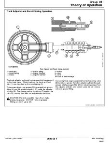
Track Adjuster and Recoil Spring Disassemble and Assemble.pdf
Track Adjuster and Recoil Spring Remove and Install.pdf
Track Carrier Roller Remove and Install.pdf
Track Chain Disassemble and Assemble.pdf
Track Chain Remove and Install.pdf
Track Chain Repair to Replace Broken Part.pdf
Track Roller Disassemble and Assemble.pdf
Track Roller Pressure Test.pdf
Track Roller Remove and Install.pdf
Track Shoe Remove and Install.pdf
02 – Axles and Suspension Systems
00 – General Information
01 – Safety
Add and Operate Attachments Safely.pdf
Add Cab Guarding for Special Uses.pdf
Avoid Backover Accidents.pdf
Avoid High-Pressure Fluids.pdf
Avoid High-Pressure Oils.pdf
Avoid Machine Tip Over.pdf
Avoid Unauthorized Machine Modifications.pdf
Avoid Work Site Hazards.pdf
Clean Debris from Machine.pdf
Clean Exhaust Filter Safely.pdf
Control Pattern Selector—If Equipped.pdf
Dispose of Waste Properly.pdf
Drive Metal Pins Safely.pdf
Exhaust Filter Ash Handling and Disposal.pdf
Follow Safety Instructions.pdf
Handle Chemical Products Safely.pdf
Inspect and Maintain ROPS.pdf
Inspect Machine.pdf
Keep Riders Off Machine.pdf
Make Welding Repairs Safely.pdf
Operate Only If Qualified.pdf
Park and Prepare for Service Safely.pdf
Prepare for Emergencies.pdf
Prevent Battery Explosions.pdf
Prevent Fires.pdf
Prevent Unintended Machine Movement.pdf
Recognize Safety Information.pdf
Remove Paint Before Welding or Heating.pdf
Service Cooling System Safely.pdf
Start Only From Operator’s Seat.pdf
Stay Clear of Moving Parts.pdf
Use and Maintain Seat Belt.pdf
Use Special Care When Lifting Objects.pdf
Use Steps and Handholds Correctly.pdf
Wear Protective Equipment.pdf
Work In Ventilated Area.pdf
03 – Torque Values
Additional Metric Cap Screw Torque Values.pdf
Inch Series Four Bolt Flange Fitting For High Pressure Service Recommendations.pdf
Metric 24° O-Ring Seal DIN 20078 Service Recommendations.pdf
Metric Bolt and Cap Screw Torque Values.pdf
O-Ring Boss Fittings In Aluminum Housing Service Recommendations—Excavators.pdf
O-Ring Face Seal Fittings With Metric Hex Nut And Stud End For High Pressure Service Recommendations.pdf
O-Ring Face Seal Fittings With Metric Hex Nut And Stud End For Standard Pressure Service Recommendations.pdf
O-Ring Face Seal Fittings With SAE Inch Hex Nut And Stud End For High Pressure Service Recommendations.pdf
Service Recommendations for 37° Flare and 30° Cone Seat Connectors.pdf
Service Recommendations For Flared Connections—Straight or Tapered Threads.pdf
Service Recommendations For Flat Face O-Ring Seal Fittings.pdf
Service Recommendations For Inch Series Four Bolt Flange Fittings.pdf
Service Recommendations for Metric Series Four Bolt Flange Fitting.pdf
Service Recommendations For Non-Restricted Banjo (Adjustable) Fittings.pdf
Service Recommendations for O-Ring Boss Fittings.pdf
Service Recommendations For O-Ring Boss Fittings With Shoulder.pdf
Unified Inch Bolt and Cap Screw Torque Values.pdf
Park Brake Valve Disassemble and Assemble.pdf
Travel Gear Case Disassemble and Assemble.pdf
Travel Gear Case Remove and Install.pdf
Travel Motor and Park Brake Disassemble and Assemble.pdf
Travel Motor and Park Brake Remove and Install.pdf
Travel Motor and Park-Brake Start-Up Procedure.pdf
04 – Engine
Engine Remove and Install.pdf
05 – Engine Auxiliary Systems
Air Cleaner Remove and Install.pdf
Coolant Recovery Tank Remove and Install.pdf
Cooling Package Remove and Install.pdf
Diesel Particulate Filter (DPF) Remove and Install.pdf
Exhaust Filter Disassemble and Assemble.pdf
Exhaust Filter Remove and Install.pdf
Fan and Fan Guard Remove and Install.pdf
Final Fuel Filter Housing Remove and Install.pdf
Fuel Cooler Remove and Install.pdf
Fuel Tank Remove and Install.pdf
Hydraulic Oil Cooler Remove and Install.pdf
Primary Fuel Filter and Water Separator Housing Remove and Install.pdf
Radiator Remove and Install.pdf
07 – Dampener Drive
Damper Drive (Flex Coupling) Remove and Install.pdf
17 – Frames, Chassis, or Supporting Structure
Counterweight Remove and Install.pdf
Welding on Machine.pdf
18 – Operator’s Station
Air Conditioner Compressor Remove and Install.pdf
Cab Remove and Install.pdf
Charge R134a System.pdf
Condenser Remove and Install.pdf
Evacuate R134a System.pdf
Flush and Purge Air Conditioning System.pdf
Heater and Air Conditioner Blower Motor Remove and Install.pdf
Heater and Air Conditioner Remove and Install.pdf
Left and Right Console Covers Remove and Install.pdf
R134a Compressor Oil Charge Check.pdf
R134a Compressor Oil Removal.pdf
R134a Refrigerant Oil Information.pdf
R134a Refrigerant Recovery, Recycling, and Charging Station Installation Procedure.pdf
Receiver-Dryer Remove and Install.pdf
Recover R134a Refrigerant.pdf
Refrigerant Cautions and Proper Handling.pdf
Seat Belt Remove and Install.pdf
Seat Remove and Install.pdf
Windowpanes Dimensions.pdf
Windowpanes Remove and Install.pdf
Windshield Remove and Install.pdf
32 – Blade (Backfill)
Blade Cylinder Disassemble and Assemble.pdf
Blade Cylinder Remove and Install.pdf
Blade Disassemble and Assemble.pdf
Blade Pilot Controller Disassemble and Assemble.pdf
Blade Pilot Valve Remove and Install.pdf
Blade Remove and Install.pdf
33 – Excavator
Apply Vacuum to Hydraulic Oil Tank.pdf
Arm Cylinder Disassemble and Assemble.pdf
Arm Cylinder Remove and Install.pdf
Arm Remove and Install.pdf
Boom Cylinder Disassemble and Assemble.pdf
Boom Cylinder Remove and Install.pdf
Boom Remove and Install.pdf
Boom Swing Cylinder Disassemble and Assemble.pdf
Boom Swing Cylinder Remove and Install.pdf
Boom Swing Pilot Valve Disassemble and Assemble.pdf
Boom Swing Pilot Valve Remove and Install.pdf
Boom Swing Post Remove and Install.pdf
Bucket Cylinder Disassemble and Assemble.pdf
Bucket Cylinder Remove and Install.pdf
Bucket Links Remove and Install.pdf
Bucket Pin-Up Data.pdf
Bucket Remove and Install.pdf
Bushing and Seal Remove and Install.pdf
Control Lever Pattern Selector Disassemble and Assemble.pdf
Control Lever Pattern Selector Remove and Install.pdf
Control Valve Disassemble and Assemble.pdf
Control Valve Remove and Install.pdf
General Hydraulic Oil Cleanup Procedure.pdf
Hydraulic Component Failure Cleanup Procedure.pdf
Hydraulic Cylinder Bleed Procedure.pdf
Hydraulic Oil Cooler Bypass Valve Remove and Install.pdf
Hydraulic Oil Tank Disassemble and Assemble.pdf
Hydraulic Oil Tank Remove and Install.pdf
Hydraulic Pump Assembly Remove and Install.pdf
Hydraulic Pump Start-Up Procedure.pdf
Inspect Pins and Bushings—Front Attachment and Blade.pdf
Pilot Pressure Regulating Valve and Filter Remove and Install.pdf
Pilot Pump Disassemble and Assemble.pdf
Pilot Pump Remove and Install.pdf
Pilot Shutoff Solenoid Valve Disassemble and Assemble.pdf
Pilot Shutoff Solenoid Valve Remove and Install.pdf
Pilot Valve (Left and Right) Disassemble and Assemble.pdf
Pilot Valve (Left and Right) Remove and Install.pdf
Pump 1 and 2 Disassemble and Assemble.pdf
Pump 1 and 2 Inspection.pdf
Pump 3 Disassemble and Assemble.pdf
Pump 3 Inspection.pdf
Solenoid Valve Manifold Remove and Install.pdf
Travel Pilot Valve Disassemble and Assemble.pdf
Travel Pilot Valve Remove and Install.pdf
43 – Swing or Pivoting System
Center Joint Air Test .pdf
Center Joint Disassemble and Assemble.pdf
Center Joint Remove and Install.pdf
Crossover Relief Valve and Make-Up Check Valve Remove and Install.pdf
Swing Bearing Disassemble and Assemble.pdf
Swing Bearing Lower Seal Install.pdf
Swing Bearing Remove and Install.pdf
Swing Bearing Upper Seal Install.pdf
Swing Gear Case Disassemble and Assemble.pdf
Swing Gear Case Remove and Install.pdf
Swing Motor and Park Brake Disassemble and Assemble.pdf
Swing Motor and Park Brake Inspection.pdf
Swing Motor and Park Brake Remove and Install.pdf
Swing Motor and Park Brake Start-Up Procedure.pdf
Upperstructure Remove And Install.pdf
9900 – Dealer Fabricated Tools
Center Joint (Rotary Manifold) Lifting Tool .pdf
DFT1087 Track Recoil Spring Disassembly and Assembly Guard Tool.pdf
DFT1112A Spacer.pdf
DFT1360 Swing Gear Roller Bearing Tool.pdf
ST4920 Track Recoil Spring Disassembly and Assembly Tool.pdf
External_Files5
H70406 – O-Ring Face Seal Fitting.pdf
T113889 – Connection.pdf
T113948 – Non-Restricted Banjo Fitting.pdf
T113957 – O-Ring Boss Fitting With Shoulder.pdf
T150148 – Cap Screw Tightening Sequence.pdf
T165793 – Blade Cylinder.pdf
T165794 – Blade Cylinder Cross Section.pdf
T166098 – Inner Race Puller.pdf
T188509 – Travel Motor Retainer and Bushing Arrangement.pdf
T188539 – Counterweight Support Beams.pdf
T188540 – Boom Bracket.pdf
T188541 – Upperstructure.pdf
T188542 – Swing Bearing.pdf
T196315 – O-Ring Boss Straight and Adjustable Fittings.pdf
T196337 – O-Ring Face Seal Fittings.pdf
T216779 – Unintended Machine Movement.pdf
T6234AC – Cone Seat Connector.pdf
T6557JB – Center Joint Air Test.pdf
T6585UY – Track Recoil Spring Disassembly and Assembly Tool.pdf
T6641DO – Center Joint Lifting Tool.pdf
T6873AD – Tapered Thread.pdf
T6873AE – Straight Thread.pdf
T6890BB – Flange Fittings.pdf
T6890BB – Four Bolt Flange Fittings.pdf
T6890BB – Metric Series Four Bolt Flange Fitting.pdf
T7029CG – ST4920 Dimensions.pdf
T7029CH – ST4920 Dimensions.pdf
T7029CI – ST4920 Dimensions.pdf
T7162AF – DFT1087 Dimensions.pdf
T7969AB – DFT1112A Spacer Dimensions.pdf
TS1693 – Moving Parts.pdf
TS1695 – Stop.pdf
TX1008208 – Seal Inspection Areas.pdf
TX1008209 – Examples Of Worn Seal Rings.pdf
TX1010083 – Bucket.pdf
TX1036620 – Swing Motor Hose Identification.pdf
TX1040135 – Travel Gear Case.pdf
TX1040324 – Piston Removal.pdf
TX1040490 – Pipe Dimensions.pdf
TX1040491 – Dust Seals.pdf
TX1040510 – Cover Removal.pdf
TX1040511 – Valve Plate and Notch.pdf
TX1040512 – Sleeve and Housing.pdf
TX1040513 – Feedback Link.pdf
TX1040593 – Piston-to-Bore Clearance.pdf
TX1040595 – Piston and Piston Slipper.pdf
TX1040596 – Cylinder Block Springs.pdf
TX1040597 – Retainer and Bushing Height.pdf
TX1041942 – Boom Swing Cylinder.pdf
TX1043234 – Swing Motor and Park Brake.pdf
TX1043361A – Hydraulic Pressure Release Button.pdf
TX1043362A – Pressure Release Button Housing.pdf
TX1043363A – Vacuum Pump Installation.pdf
TX1045655 – Boom Swing Control.pdf
TX1092021 – Pilot Shutoff Solenoid Valve.pdf
TX1092915A – Seal.pdf
TX1092921 – Swing Bearing Cross Section.pdf
TX1093550A – Track Shoe (steel track shoe shown).pdf
TX1096302 – Pilot Control Valve.pdf
TX1096325 – Spring Removal Tools.pdf
TX1096326 – Snap Ring Installation Tool.pdf
TX1098001 – Track Pin.pdf
TX1098002 – Bushing.pdf
TX1098003 – Track Link Assembly.pdf
TX1098008 – Track Pin.pdf
TX1098035 – Bushing.pdf
TX1098617 – Refrigerant Recovery, Recycling, and Charging Station.pdf
TX1113412 – Swing Bearing Lower Seal.pdf
TX1122068 – Swing Bearing Cap Screws.pdf
TX1124992 – Swing Bearing Cross Section.pdf
TX1124993 – Swing Bearing Cross Section.pdf
TX1128437A – Pilot Control Levers (shown tied back).pdf
TX1128440A – Wiring Cover.pdf
TX1128441A – Heater and Air Conditioner and Wiring Harness.pdf
TX1132651 – Track Shoe Cap Screw and Nut.pdf
TX1132924A – Seat Belt.pdf
TX1132925A – Buckle.pdf
TX1133214 – Track Recoil Spring Tool.pdf
TX1133218 – Installing Track Adjuster in Disassembly and Assembly Tool.pdf
TX1133220 – Track Recoil Spring Guard Tool.pdf
TX1133223 – Track Recoil Spring Guard Tool—Guard Raised.pdf
TX1133703A – Arm Rest.pdf
TX1133704A – Rear Switch Console.pdf
TX1133705A – Pilot Control Lever Boot.pdf
TX1133706A – Pilot Control Lever.pdf
TX1133707A – Right Switch Console.pdf
TX1133723A – Rear Switch Console (bottom view).pdf
TX1133724A – Right Switch Console (bottom view).pdf
TX1133785A – Left Console.pdf
TX1133787A – Boot.pdf
TX1133788A – Left Console (shown with inside cover removed).pdf
TX1134367 – Control Lever Pattern Selector.pdf
TX1134741A – Fuel Injectors.pdf
TX1134743A – Exhaust Filter Connectors.pdf
TX1134758A – Engine Lifting Points.pdf
TX1135532A – Exhaust Filter.pdf
TX1135533 – Exhaust Filter (exploded view).pdf
TX1136128A – Cylinder Pin.pdf
TX1136470 – Excavator Bucket Pin-Up Data.pdf
TX1137195 – Grease Fitting.pdf
TX1137198A – Master Pin.pdf
TX1137200 – Master Pin.pdf
TX1137323 – Boom-to-Arm Angle.pdf
TX1137758A – Pilot Pump.pdf
TX1137760A – Hydraulic Pump.pdf
TX1138049A – Covers.pdf
TX1138113A – Intake and Coolant Hoses.pdf
TX1138121A – Engine Harness Electrical Connectors.pdf
TX1138124A – Air Conditioner Compressor.pdf
TX1138134A – High-Pressure Fuel Pump.pdf
TX1138143A – Return Fuel Hose and Engine Harness Connectors.pdf
TX1138146A – Starter Motor.pdf
TX1138148A – Alternator.pdf
TX1138180 – Track Chain.pdf
TX1138248A – Cross Member Cover.pdf
TX1138251 – Front Idler.pdf
TX1138254A – Front Idler.pdf
TX1138255A – Sprocket.pdf
TX1138265A – Hydraulic Pump Assembly.pdf
TX1138266A – Support Assembly.pdf
TX1138282A – Engine Cover.pdf
TX1138283A – Washer Fluid Bracket.pdf
TX1138284A – Counterweight Cap Screws.pdf
TX1138403 – Control Valve Mounting.pdf
TX1138410A – Control Valve (front).pdf
TX1138532A – Flywheel Cover.pdf
TX1138579A – Cab Harness Connectors.pdf
TX1138609A – Cabin Air Filter Duct.pdf
TX1138611A – Windshield Washer Tank Hose.pdf
TX1138612 – Cab Mount Locations.pdf
TX1138637A – Travel Gear Case.pdf
TX1138640A – Travel Gear Case Cover.pdf
TX1138655A – Hydraulic Pump Suction Line.pdf
TX1138671A – Air Conditioner Lines.pdf
TX1138675A – Support Assembly.pdf
TX1138699 – Travel Motor and Park Brake Disassemble and Assemble.pdf
TX1138715A – Hydraulic Pump Compartment.pdf
TX1138716A – Hydraulic Oil Tank (rear).pdf
TX1138720 – Hydraulic Lines.pdf
TX1138749A – Travel Motor and Park Brake Start-Up Procedure.pdf
TX1138822A – Control Valve Covers.pdf
TX1138826A – Engine Cover.pdf
TX1138828A – Exhaust Filter Connections.pdf
TX1138831A – Exhaust Filter.pdf
TX1138841A – Primary Fuel Filter.pdf
TX1138846A – Shutoff Valve.pdf
TX1138847A – Final Fuel Filter.pdf
TX1138851A – Hydraulic Oil Cooler Bypass Valve.pdf
TX1138853A – Return Line.pdf
TX1138910A – Control Lever Pattern Selector Cover and Door.pdf
TX1138911A – Control Lever Pattern Selector.pdf
TX1138913A – Track Carrier Roller.pdf
TX1138918A – Air Filter Connection.pdf
TX1138922 – Track Roller Disassemble and Assemble.pdf
TX1138929A – Track Roller.pdf
TX1138986A – Solenoid Valve Manifold.pdf
TX1138998A – Track Roller Oil Leakage Test Components.pdf
TX1139000A – Radiator Access Door.pdf
TX1139002A – Cooling Package Covers.pdf
TX1139003A – Upper Radiator Hose.pdf
TX1139004A – Lower Radiator Hose.pdf
TX1139005A – Radiator.pdf
TX1139019A – Fuel Cooler.pdf
TX1139020A – Condenser.pdf
TX1139023 – Solenoid Valves.pdf
TX1139055A – Fuel Cooler.pdf
TX1139092 – Park Brake Valve Disassemble and Assemble.pdf
TX1139116A – Fan Guard.pdf
TX1139122A – Fan.pdf
TX1139123A – Fan Pulley.pdf
TX1139133A – Travel Pilot Valve.pdf
TX1139134A – Front Cover (below cab).pdf
TX1139136A – Travel Pilot Valve (bottom view).pdf
TX1139149A – Auxiliary Flow Control Valve.pdf
TX1139152A – Auxiliary Flow Control Valve (bottom).pdf
TX1139154A – Pilot Pressure Regulating Valve Mounting Bracket Cap Screws.pdf
TX1139176A – Pilot Pressure Regulating Valve.pdf
TX1139209A – Coolant Recovery Tank.pdf
TX1139329A – Seat (front of seat shown).pdf
TX1139330A – Air Conditioner Compressor.pdf
TX1139384A – Hydraulic Oil Tank (front and side).pdf
TX1139386A – Control Valve Compartment.pdf
TX1139464A – Fuel Regulator.pdf
TX1139473A – Hydraulic Hoses.pdf
TX1139477A – Arm Cylinder Pin.pdf
TX1139511A – Rear Frame.pdf
TX1139515A – Hydraulic Lines.pdf
TX1139516A – Hydraulic Lines.pdf
TX1139702 – Track Adjuster Cylinder.pdf
TX1139703A – Track Adjuster and Recoil Spring.pdf
TX1139704A – Track Adjuster and Recoil Spring.pdf
TX1139731A – Condenser.pdf
TX1139732A – Fuel Cooler.pdf
TX1139733A – Cooling Package Access Door.pdf
TX1139734A – Cooling Package Covers.pdf
TX1139735A – Upper Cooling Package Hoses.pdf
TX1139736A – Paneling.pdf
TX1139737A – Cooling Package.pdf
TX1139738A – Lower Radiator Hoses.pdf
TX1139739A – Lower Hydraulic Oil Cooler Hose.pdf
TX1139740A – Cooling Package Mount.pdf
TX1139741A – Lifting Device.pdf
TX1139745A – Air Filter Housing.pdf
TX1139761A – Boom Swing Pilot Valve Line Connections.pdf
TX1139875A – Boom Swing Pilot Valve.pdf
TX1139893A – Pilot Shutoff Solenoid Valve.pdf
TX1140155A – Cooling Package.pdf
TX1140200A – Boom Pin.pdf
TX1140201A – Boom Cylinder Pin.pdf
TX1140218A – Boom Light Connector.pdf
TX1140221A – Arm Pin.pdf
TX1140308A – Pilot Valve (left side shown).pdf
TX1140311A – Bucket Links.pdf
TX1140312A – Bucket and Arm Links.pdf
TX1140433 – Boom, Arm, Bucket, and Blade Pins and Bushings.pdf
TX1140444 – Hydraulic Valves.pdf
TX1140507 – Pump 1 and 2 Disassemble.pdf
TX1140580 – Boom Cylinder.pdf
TX1140582 – Bucket Cylinder.pdf
TX1140583 – Arm Cylinder.pdf
TX1140587A – Swing Gear Case Assembly.pdf
TX1140591 – Swing Gear Case.pdf
TX1140600 – Second Stage Carrier Pins.pdf
TX1140641 – Swing Post.pdf
TX1140711 – Pump 3 Disassemble and Assemble.pdf
TX1140714 – Valve Plate and Notch.pdf
TX1140795 – Pilot Pump Components.pdf
TX1140866 – Travel Pilot Valve Components.pdf
TX1140872 – Blade.pdf
TX1140884 – Lifting Brackets.pdf
TX1140885 – Position of Machine.pdf
TX1140909 – Swing Bearing (exploded view).pdf
TX1140914A – Blade Pilot Valve.pdf
TX1140921 – Blade Pilot Vale.pdf
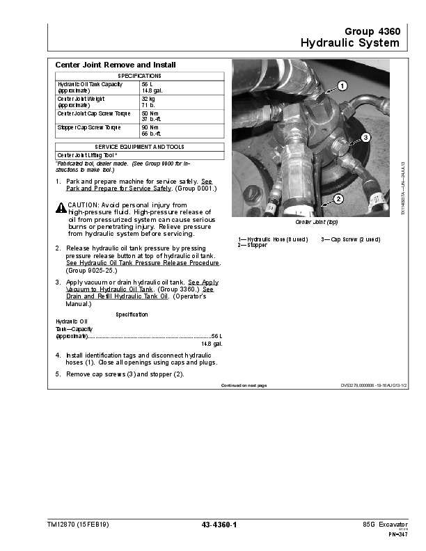
TX1140937A – Center Joint (top).pdf
TX1140938A – Center Joint (bottom).pdf
TX1140945A – Blade Cylinder.pdf
TX1140965A – Blade.pdf
TX1141046 – Center Joint Components.pdf
TX1141051 – Hydraulic Oil Tank.pdf
TX1141148A – Cover.pdf
TX1141254 – Control Valve—3-Spool Section.pdf
TX1141306A – Hydraulic Hoses.pdf
TX1141312A – Boom Cylinder Rod End.pdf
TX1141313A – Cylinder Pin.pdf
TX1141332 – Swing Park Brake Release Pilot Valve.pdf
TX1141333 – Bucket Spool.pdf
TX1141334 – Boom 1 Spool.pdf
TX1141336 – Arm 2 Spool.pdf
TX1141337 – Swing Spool.pdf
TX1141338 – Arm In Flow Combiner Selector Valve.pdf
TX1141339 – Auxiliary Flow Combiner Valve Spool.pdf
TX1141341A – Hydraulic Cylinder Pin and Hoses.pdf
TX1141342A – Cylinder Pin.pdf
TX1141400A – Swing Motor and Park Brake.pdf
TX1141414 – Swing Motor and Park Brake.pdf
TX1141516 – Boom Reduced Leakage Valve—Switched Valve.pdf
TX1141517 – Check Valve (lift check)—Arm 2 Neutral Passage.pdf
TX1141518 – Check Valve (lift check) and System Relief Valve Isolation Check Valve.pdf
TX1141519 – Check Valve (lift check)—Right Travel Neutral Passage.pdf
TX1141520 – Check Valve (lift check)—Bucket Flow Combiner Circuit.pdf
TX1141523A – Hydraulic Hoses.pdf
TX1141524A – Cylinder Pin.pdf
TX1141528A – JT30043-30 Hex Piston Nut Wrench.pdf
TX1141529A – Sliding Housing and Stand Assembly.pdf
TX1141530A – Ring Compressor.pdf
TX1141535 – Check Valve (lift check)—Boom Up Flow Combiner Circuit.pdf
TX1141536 – Right Travel Spool.pdf
TX1141538 – Flow Combiner Valve.pdf
TX1141539 – Boom 2 Spool.pdf
TX1141540 – Arm 1 Spool.pdf
TX1141541 – Auxiliary Spool 1.pdf
TX1141565A – Rear (rear of seat shown).pdf
TX1141584A – Track Shoe (rubber track shoe shown).pdf
TX1141594A – Boom Swing Cylinder.pdf
TX1141604A – Condenser.pdf
TX1141643A – Receiver-Dryer.pdf
TX1141656 – Upper Front Glass.pdf
TX1141657 – Lower Front Glass.pdf
TX1141660 – Cab Roof Glass.pdf
TX1141661 – Cab Door.pdf
TX1141663 – Rear Cab Glass.pdf
TX1141664 – Right Side Cab Glass.pdf
TX1141665 – Rear Left Side Sliding Window (upper).pdf
TX1141666 – Rear Left Side Sliding Window (lower).pdf
TX1141680A – Bucket Pins.pdf
TX1141726A – Windshield Latch (left side).pdf
TX1141727A – Windshield Latch (right side).pdf
TX1141728A – Windshield Roller (right side).pdf
TX1141729A – Windshield Roller (left side).pdf
TX1141730A – Windshield Wiper Motor Connector.pdf
TX1141738 – Control Valve—Relief Valves.pdf
TX1141743 – Control Valve—6-Spool Section.pdf
TX1141744 – Boom Swing Spool.pdf
TX1141745 – Control Valve—5-Spool Section.pdf
TX1141746 – Blade Spool.pdf
TX1141747 – Control Valve—Poppets, Plugs, and Boom Reduced Leakage Valve.pdf
TX1141869 – Plunger and Bore.pdf
TX1141870A – Panels.pdf
TX1141871 – Plunger and Shoe.pdf
TX1141872A – Right Side of Fuel Tank.pdf
TX1141874A – Left Side of Fuel Tank.pdf
TX1141880A – Under Tank.pdf
TX1141891A – Cover.pdf
TX1142100A – Boom Swing Cylinder Hose.pdf
TX1142247 – Swing Gear Roller Bearing Tool.pdf
TX1142298A – Cover Assembly.pdf
TX1142356A – Adjusting Washer.pdf
TX1175575 – Track Adjuster Cylinder.pdf
Table of Contents – Expanded View
Foreword
Technical Information Feedback Form
General Information
Safety
Recognize Safety Information
Follow Safety Instructions
Operate Only If Qualified
Wear Protective Equipment
Avoid Unauthorized Machine Modifications
Control Pattern Selector—If Equipped
Add Cab Guarding for Special Uses
Inspect Machine
Stay Clear of Moving Parts
Avoid High-Pressure Fluids
Avoid High-Pressure Oils
Work In Ventilated Area
Prevent Fires
Prevent Battery Explosions
Handle Chemical Products Safely
Decommissioning — Proper Recycling and Disposal of Fluids and Components
Exhaust Filter Ash Handling and Disposal
Prepare for Emergencies
Clean Debris from Machine
Use Steps and Handholds Correctly
Start Only From Operator’s Seat
Use and Maintain Seat Belt
Prevent Unintended Machine Movement
Avoid Work Site Hazards
Keep Riders Off Machine
Avoid Backover Accidents
Inspect and Maintain ROPS
Avoid Machine Tip Over
Use Special Care When Lifting Objects
Add and Operate Attachments Safely
Park and Prepare for Service Safely
Service Cooling System Safely
Remove Paint Before Welding or Heating
Make Welding Repairs Safely
Drive Metal Pins Safely
Clean Exhaust Filter Safely
Torque Values
Metric Bolt and Cap Screw Torque Values
Additional Metric Cap Screw Torque Values
Unified Inch Bolt and Cap Screw Torque Values
Service Recommendations for 37° Flare and 30° Cone Seat Connectors
Service Recommendations for O-Ring Boss Fittings
Service Recommendations for Flared Connections—Straight or Tapered Threads
Service Recommendations for Flat Face O-Ring Seal Fittings
O-Ring Boss Fittings in Aluminum Housing Service Recommendations—Excavators
O-Ring Face Seal Fittings With SAE Inch Hex Nut and Stud End for High-Pressure Service Recommendations
O-Ring Face Seal Fittings With Metric Hex Nut and Stud End for Standard Pressure Service Recommendations
O-Ring Face Seal Fittings With Metric Hex Nut and Stud End for High-Pressure Service Recommendations
Service Recommendations for Metric Series Four Bolt Flange Fitting
Service Recommendations For Inch Series Four Bolt Flange Fittings
Inch Series Four Bolt Flange Fitting for High-Pressure Service Recommendations
Service Recommendations For Non-Restricted Banjo (Adjustable) Fittings
Service Recommendations For O-Ring Boss Fittings With Shoulder
Metric 24° O-Ring Seal DIN 20078 Service Recommendations
Tracks
Track System
Track Roller Remove and Install
Track Roller Disassemble and Assemble
Track Roller Pressure Test
Track Carrier Roller Remove and Install
Inspect Metal Face Seals
Track Shoe Remove and Install
Track Chain Remove and Install
Track Chain Disassemble and Assemble
Track Chain Repair to Replace Broken Part
Sprocket Remove and Install
Front Idler Remove and Install
Front Idler Disassemble and Assemble
Track Adjuster and Recoil Spring Remove and Install
Track Adjuster and Recoil Spring Disassemble and Assemble
Axles and Suspension Systems
Axle Shaft, Bearings, and Reduction Gears
Travel Gear Case Remove and Install
Travel Gear Case Disassemble and Assemble
Hydraulic System
Travel Motor and Park Brake Remove and Install
Travel Motor and Park Brake Disassemble and Assemble
Park Brake Valve Disassemble and Assemble
Travel Motor and Park-Brake Start-Up Procedure
Engine
Removal and Installation
Engine Remove and Install
Engine Auxiliary Systems
Cooling System
Radiator Remove and Install
Hydraulic Oil Cooler Remove and Install
Fuel Cooler Remove and Install
Cooling Package Remove and Install
Fan and Fan Guard Remove and Install
Coolant Recovery Tank Remove and Install
Intake System
Air Cleaner Remove and Install
External Exhaust Systems
Diesel Particulate Filter (DPF) Remove and Install
Exhaust Filter Remove and Install
Exhaust Filter Disassemble and Assemble
External Fuel Supply Systems
Fuel Tank Remove and Install
Primary Fuel Filter and Water Separator Housing Remove and Install
Final Fuel Filter Housing Remove and Install
Damper Drive (Flex Coupling)
Elements
Damper Drive (Flex Coupling) Remove and Install
Frame or Supporting Structure
Frame Installation
Welding on Machine
Chassis Weights
Counterweight Remove and Install
Operator’s Station
Removal and Installation
Cab Remove and Install
Operator Enclosure
Windshield Remove and Install
Windowpanes Remove and Install
Windowpanes Dimensions
Seat and Seat Belt
Seat Remove and Install
Seat Belt Remove and Install
Left and Right Console Covers Remove and Install
Heating and Air Conditioning
Refrigerant Cautions and Proper Handling
Flush and Purge Air Conditioning System
R134a Refrigerant Oil Information
R134a Refrigerant Recovery, Recycling, and Charging Station Installation Procedure
R134a Compressor Oil Charge Check
R134a Compressor Oil Removal
Recover R134a Refrigerant
Evacuate R134a System
Charge R134a System
Air Conditioner Compressor Remove and Install
Condenser Remove and Install
Heater and Air Conditioner Remove and Install
Heater and Air Conditioner Blower Motor Remove and Install
Receiver-Dryer Remove and Install
Blade (Backfill)
Blades
Blade Remove and Install
Blade Disassemble and Assemble
Hydraulic System
Blade Cylinder Remove and Install
Blade Cylinder Disassemble and Assemble
Blade Pilot Valve Remove and Install
Blade Pilot Controller Disassemble and Assemble
Excavator
Buckets
Bucket Remove and Install
Bucket Pin-Up Data
Frames
Bucket Links Remove and Install
Arm Remove and Install
Boom Remove and Install
Boom Swing Post Remove and Install
Inspect Pins and Bushings—Front Attachment and Blade
Cylinder Specifications
Bushing and Seal Remove and Install
Hydraulic System
Apply Vacuum to Hydraulic Oil Tank
General Hydraulic Oil Cleanup Procedure
Hydraulic Component Failure Cleanup Procedure
Hydraulic Pump Assembly Remove and Install
Pump 1 and 2 Disassemble and Assemble
Pump 1 and 2 Inspection
Pump 3 Disassemble and Assemble
Pump 3 Inspection
Pilot Pump Remove and Install
Pilot Pump Disassemble and Assemble
Hydraulic Pump Start-Up Procedure
Pilot Pressure Regulating Valve and Filter Remove and Install
Pilot Shutoff Solenoid Valve Remove and Install
Pilot Shutoff Solenoid Valve Disassemble and Assemble
Solenoid Valve Manifold Remove and Install
Solenoid Valve Remove and Install—Travel Speed (SI) and Torque Control (ST)
Pilot Valve (Left and Right) Remove and Install
Pilot Valve (Left and Right) Disassemble and Assemble
Travel Pilot Valve Remove and Install
Travel Pilot Valve Disassemble and Assemble
Boom Swing Pilot Valve Remove and Install
Boom Swing Pilot Valve Disassemble and Assemble
Control Valve Remove and Install
Control Valve Disassemble and Assemble
Control Lever Pattern Selector Remove and Install
Control Lever Pattern Selector Disassemble and Assemble
Hydraulic Oil Tank Remove and Install
Hydraulic Oil Tank Disassemble and Assemble
Hydraulic Oil Cooler Bypass Valve Remove and Install
Boom Cylinder Remove and Install
Boom Cylinder Disassemble and Assemble
Arm Cylinder Remove and Install
Arm Cylinder Disassemble and Assemble
Bucket Cylinder Remove and Install
Bucket Cylinder Disassemble and Assemble
Boom Swing Cylinder Remove and Install
Boom Swing Cylinder Disassemble and Assemble
Hydraulic Cylinder Bleed Procedure
Swing or Pivoting System
Mechanical Drive Elements
Swing Gear Case Remove and Install
Swing Gear Case Disassemble and Assemble
Upperstructure Remove And Install
Swing Bearing Remove and Install
Swing Bearing Disassemble and Assemble
Swing Bearing Upper Seal Install
Swing Bearing Lower Seal Install
Hydraulic System
Center Joint Remove and Install
Center Joint Disassemble and Assemble
Center Joint Air Test
Swing Motor and Park Brake Remove and Install
Swing Motor and Park Brake Disassemble and Assemble
Swing Motor and Park Brake Inspection
Swing Motor and Park Brake Start-Up Procedure
Crossover Relief Valve and Make-Up Check Valve Remove and Install
Dealer Fabricated Tools
ST4920 Track Recoil Spring Disassembly and Assembly Tool
DFT1112A Spacer
DFT1087 Track Recoil Spring Disassembly and Assembly Guard Tool
Center Joint (Rotary Manifold) Lifting Tool
DFT1360 Swing Gear Roller Bearing Tool

John Deere 85G Excavator Repair Technical Manual (TM12870)


INSTANT DOWNLOAD


Posted on

John Deere 85G Excavators Technical Manual (Operation & Test TM12867)


INSTANT DOWNLOAD


Complete Diagnosis & Test Technical manual with Electrical Wiring Diagrams for John Deere 85G Excavator, with all the workshop information to service & diagnose.

John Deere 85G Excavator workshop diagnosis service manual includes:
* Numbered table of contents easy to use so that you can find the information you need fast.
* Detailed sub-steps expand on repair procedure information
* Numbered instructions guide you through every repair procedure step by step.
* Troubleshooting and electrical service procedures are combined with detailed wiring diagrams for ease of use.
* Notes, cautions and warnings throughout each chapter pinpoint critical information.
* Bold figure number help you quickly match illustrations with instructions.
* Detailed illustrations, drawings and photos guide you through every procedure.
* Enlarged inset helps you identify and examine parts in detail.

TM12867 English – Operation & Test (John Deere 85G Excavator).pdf
TM12867 (05JUN19) – John Deere 85G Excavator (PIN 1FF085GX_ _J017001— ) Operation & Test Technical Manual.PDF
tm12868 French – Excavatrice 85G.pdf
tm12869 Spanish – Excavadora 85G.pdf

Total Pages: 1,012 pages
File Format: PDF (bookmarked, ToC, Searchable, Printable)
Language: English French Spanish

TABLE OF CONTENTS
Section 9000: General Information….21
Group 01: Safety….21
Recognize Safety Information….24
Follow Safety Instructions….25
Operate Only If Qualified….26
Wear Protective Equipment….27
Avoid Unauthorized Machine Modifications….28
Control Pattern Selector—If Equipped….29
Add Cab Guarding for Special Uses….30
Inspect Machine….31
Stay Clear of Moving Parts….32
Avoid High-Pressure Fluids….33
Avoid High-Pressure Oils….34
Work In Ventilated Area….35
Prevent Fires….36
Prevent Battery Explosions….37
Handle Chemical Products Safely….38
Decommissioning — Proper Recycling and Disposal of Fluids and Components….39
Exhaust Filter Ash Handling and Disposal….40
Prepare for Emergencies….41
Clean Debris from Machine….42
Use Steps and Handholds Correctly….43
Start Only From Operator's Seat….44
Use and Maintain Seat Belt….45
Prevent Unintended Machine Movement….46
Avoid Work Site Hazards….47
Keep Riders Off Machine….49
Avoid Backover Accidents….50
Inspect and Maintain ROPS….51
Avoid Machine Tip Over….52
Use Special Care When Lifting Objects….54
Add and Operate Attachments Safely….55
Park and Prepare for Service Safely….56
Service Cooling System Safely….57
Remove Paint Before Welding or Heating….58
Make Welding Repairs Safely….59
Drive Metal Pins Safely….60
Clean Exhaust Filter Safely….61
Section 9001: Diagnostics….64
Group 10: Main Controller (MCZ) Diagnostic Trouble Codes….73
Main Controller (MCZ) Diagnostic Trouble Codes….73
Controller Area Network 0 (CAN 0) Circuit Diagnostics….74
Controller Area Network 1 (CAN 1) Circuit Diagnostics….88
Interface Controller Area Network (N-CAN) Diagnostics….105
011000.02 – Abnormal EEPROM….64
011001.02 – Abnormal RAM….64
011002.02 – Abnormal A/D Converter….64
011003.03 – Abnormal Sensor Voltage….64
011006.02 – Engine Controller Communication Error….64
011007.02 – (CAN 0) Data Converter Communication Error 1….64
011008.02 – (CAN 1) Data Converter Communication Error 2….64
011009.02 – (CAN 0) Monitor Controller Communication Error 1….64
011010.02 – (CAN 1) Monitor Controller Communication Error 2….64
011100.02 – Abnormal Engine Speed….64
011101.03 – Engine Control Dial Sensor Circuit High Input….64
011101.04 – Engine Control Dial Sensor Circuit Low Input….64
011304.03 – Travel Pilot Pressure Sensor Circuit High Input….64
011304.04 – Travel Pilot Pressure Sensor Circuit Low Input….64
011307.03 – Front Pilot Pressure Sensor Circuit High Input….64
011307.04 – Front Pilot Pressure Sensor Circuit Low Input….64
011401.02 – Torque Pressure Solenoid Valve Abnormal Feedback….64
011401.03 – Torque Pressure Solenoid Valve Feedback High Current….64
011401.04 – Torque Pressure Solenoid Valve Feedback Low Current….64
011407.02 – Travel Mode Selector Solenoid Valve Abnormal Feedback….64
011407.03 – Travel Mode Selector Solenoid Valve Feedback High Current….64
011407.04 – Travel Mode Selector Solenoid Valve Feedback Low Current….64
011408.02 – 2-Spool Solenoid Valve Unit (SJ) Abnormal Feedback….64
011408.03 – 2-Spool Solenoid Valve Unit (SJ) Feedback High Input….64
011408.04 – 2-Spool Solenoid Valve Unit (SJ) Feedback Low Input….64
011409.02 – 2-Spool Solenoid Valve Unit (SZ) Abnormal Feedback….64
011409.03 – 2-Spool Solenoid Valve Unit (SZ) Feedback High Input….64
011409.04 – 2-Spool Solenoid Valve Unit (SZ) Feedback Low Input….65
011434.02 – Attachment Relief 1 (Upper) Proportional Solenoid Valve Abnormal Feedback….65
011434.03 – Attachment Relief 1 (Upper) Proportional Solenoid Valve Feedback High Current….65
011434.04 – Attachment Relief 1 (Upper) Proportional Solenoid Valve Feedback Low Current….65
011435.02 – Attachment Relief 2 (Lower) Proportional Solenoid Valve Abnormal Feedback….65
011435.03 – Attachment Relief 2 (Lower) Proportional Solenoid Valve Feedback High Current….65
011435.04 – Attachment Relief 2 (Lower) Proportional Solenoid Valve Feedback Low Current….65
011436.02 – Breaker Relief Proportional Solenoid Valve Abnormal Feedback….65
011436.03 – Breaker Relief Proportional Solenoid Valve Feedback High Current….65
011436.04 – Breaker Relief Proportional Solenoid Valve Feedback Low Current….65
011458.02 – (Auxiliary) Discontinuity of Selector Valve….65
011459.02 – Discontinuity of Auto Shut-Down Control Power Line….65
011810.03 – Electric Lever Operating Pressure Sensor 1 High Voltage….65
011810.04 – Electric Lever Operating Pressure Sensor 1 Low Voltage….65
011811.03 – Electric Lever Operating Pressure Sensor 2 High Voltage….65
011811.04 – Electric Lever Operating Pressure Sensor 2 Low Voltage….65
011812.02 – OPT Electric Lever 1 Neutral Abnormal….65
011813.02 – OPT Electric Lever 1 Abnormal Operation….747
011814.02 – OPT Electric Lever 2 Neutral Abnormal….65
011815.02 – OPT Electric Lever 2 Abnormal Operation….747
011816.02 – OPT Solenoid 1 Feedback Abnormal….65
011816.03 – OPT Solenoid 1 Feedback Current High….65
011816.04 – OPT Solenoid 1 Feedback Current Low….65
011817.02 – OPT Solenoid 2 Feedback Abnormal….65
011817.03 – OPT Solenoid 2 Feedback Current High….65
011817.04 – OPT Solenoid 2 Feedback Current Low….65
011818.02 – OPT Solenoid 3 Feedback Abnormal….65
011818.03 – OPT Solenoid 3 Feedback Current High….65
011818.04 – OPT Solenoid 3 Feedback Current Low….65
011819.02 – OPT Solenoid 4 Feedback Abnormal….65
011819.03 – OPT Solenoid 4 Feedback Current High….65
011819.04 – OPT Solenoid 4 Feedback Current Low….65
015011.03 – Hydraulic Oil Temperature Sensor Circuit High Input (Pilot)….65
015011.04 – Hydraulic Oil Temperature Sensor Circuit Low Input (Pilot)….66
015016.03 – Right Analog Stroke Sensor Circuit High Input….66
015016.04 – Right Analog Stroke Sensor Circuit Low Input….66
015017.03 – Left Analog Stroke Sensor Circuit High Input….66
015017.04 – Left Analog Stroke Sensor Circuit Low Input….66
020010.02 – Exhaust Filter Alarm….66
020011.02 – Electric Lever Alarm….66
020012.02 – Line Filter Restriction Alarm….66
020303.02 – Electric Lever Pilot Cut Alarm….66
Group 20: Engine Control Unit (ECU) Diagnostic Trouble Codes….228
Engine Control Unit (ECU) Diagnostic Trouble Codes….228
000051.03 – Intake Throttle Opening Sensor Fault (High Voltage) (P02E9) (00033-03)….66
000051.04 – Intake Throttle Opening Sensor Fault (Low Voltage) (P02E8) (00033-04)….66
000091.03 – Acceleration Sensor 1 Fault (High Voltage) (P0123) (0005B-03)….66
000091.04 – Acceleration Sensor 1 Fault (Low Voltage) (P0122) (0005B-04)….66
000100.01 – Low Oil Pressure Fault Alarm (P1198) (00064-01)….66
000100.04 – Oil Pressure Switch Open Circuit (P1192) (00064-04)….66
000102.03 – Exhaust Gas Recirculation (EGR) Low Pressure Side Sensor Fault (High Voltage) (P0238) (00066-03)….66
000102.04 – Exhaust Gas Recirculation (EGR) Low Pressure Side Sensor Fault (Low Voltage) (P0237) (00066-04)….66
000105.03 – Intake Air Temperature Sensor Fault (High Voltage) (P040D) (00069-03)….66
000105.04 – Intake Air Temperature Sensor Fault (Low Voltage) (P040C) (00069-04)….66
000108.03 – Atmospheric Pressure Sensor Fault (High Voltage) (P2229) (0006C-03)….66
000108.04 – Atmospheric Pressure Sensor Fault (Low Voltage) (P2228) (0006C-04)….66
000108.10 – Atmospheric Pressure Sensor Characteristic Fault (P1231) (0006C-0A)….66
000110.00 – Cooling Water Temperature Sensor Temperature Abnormal High (Overheat) (P0217) (0006E-00)….66
000110.03 – Cooling Water Temperature Sensor Fault (High Voltage) (P0118) (0006E-03)….66
000110.04 – Cooling Water Temperature Sensor Fault (Low Voltage) (P0117) (0006E-04)….66
000157.00 – Actual Rail Pressure Rise Error (P0088) (0009D-00)….66
000157.03 – Rail Pressure Sensor Fault (High Voltage) (P0193) (0009D-03)….66
000157.04 – Rail Pressure Sensor Fault (Low Voltage) (P0192) (0009D-04)….66
000157.15 – Rail Pressure Deviation Error During the Actual Rail Pressure Rise (P0093) (0009D-0F)….66
000157.16 – Pressure Limit Valve (PLV) Open Valve (P000F) (0009D-10)….67
000157.18 – Rail Pressure Deviation Error During the Actual Rail Pressure Drop (P0094) (0009D-12)….67
000167.01 – Charge Alarm (P1568) (000A7-01)….67
000167.05 – Charge Switch Open Circuit (P1562) (000A7-05)….67
000172.03 – New Air Temperature Sensor Fault (High Voltage) (P0113) (000AC-03)….67
000172.04 – New Air Temperature Sensor Fault (Low Voltage) (P0112) (000AC-04)….67
000173.03 – Exhaust Air Temperature Sensor Fault (High Voltage) (P0546) (000AD-03)….67
000173.04 – Exhaust Air Temperature Sensor Fault (Low Voltage) (P0545) (000AD-04)….67
000174.00 – Fuel Temperature Sensor Temperature Abnormal High (P0168) (000AE-00)….67
000174.03 – Fuel Temperature Sensor Fault (High Voltage) (P0183) (000AE-03)….67
000174.04 – Fuel Temperature Sensor Fault (Low Voltage) (P0182) (000AE-04)….67
000190.00 – Overspeed (P0219) (000BE-00)….67
000412.03 – Exhaust Gas Recirculation (EGR) Gas Temperature Sensor Fault (High Voltage) (P041D) (0019C-03)….67
000412.04 – Exhaust Gas Recirculation (EGR) Gas Temperature Sensor Fault (Low Voltage) (P041C) (0019C-04)….67
000630.12 – EEPROM Memory Deletion Error (P0601) (00276-0C)….67
000633.05 – High Pressure Pump Drive Circuit (Open Circuit) (P0627) (00279-05)….67
000633.06 – High Pressure Pump Drive Circuit (High Side Ground Short Circuit) (P1642) (00279-06)….67
000651.03 – Injector 1 Short Circuit (4TNV) (P1271) (0028B-03)….67
000651.05 – Injector 1 Open Circuit (Inherent Location of the Injector) (4TNV) (P0204) (0028B-05)….67
000651.06 – Injector 1 Coil Short Circuit (4TNV) (P0271) (0028B-06)….67
000651.11 – Injector 1 Unclassified (4TNV) (P1272) (0028B-0B)….67
000652.03 – Injector 4 Short Circuit (P1268) (0028C-03)….67
000652.05 – Injector 4 Open Circuit (Inherent Location of the Injector) (P0203) (0028C-05)….67
000652.06 – Injector 4 Coil Short Circuit (P0268) (0028C-06)….67
000652.11 – Injector 4 Unclassified (P1269) (0028C-0B)….67
000653.03 – Injector 2 Short Circuit (P1265) (0028D-03)….67
000653.05 – Injector 2 Open Circuit (Inherent Location of the Injector) (P0202) (0028D-05)….67
000653.06 – Injector 2 Coil Short Circuit (P0265) (0028D-06)….67
000653.11 – Injector 2 Unclassified (P1266) (0028D-0B)….67
000654.03 – Injector 3 Short Circuit (P1262) (0028E-03)….67
000654.05 – Injector 3 Open Circuit (Inherent Location of the Injector) (P0201) (0028E-05)….67
000654.06 – Injector 3 Coil Short Circuit (P0262) (0028E-06)….68
000654.11 – Injector 3 Unclassified (P1263) (0028E-0B)….68
001209.03 – Exhaust Gas Recirculation (EGR) High Pressure Side Sensor Fault (High Voltage) (P0473) (004B9-03)….68
001209.04 – Exhaust Gas Recirculation (EGR) High Pressure Side Sensor Fault (Low Voltage) (P0472) (004B9-04)….68
001485.02 – Power Off Without Main Relay Self Holding (P068A) (005CD-02)….68
001485.07 – Main Relay Contact Stuck (P068B) (005CD-07)….68
002791.00 – Exhaust Gas Recirculation (EGR) High Voltage Malfunction (P0404) (00AE7-00)….68
002791.01 – Exhaust Gas Recirculation (EGR) Low Voltage Malfunction (P0404) (00AE7-01)….68
002791.01 – Exhaust Gas Recirculation (EGR) Low Voltage Malfunction (P1404) (00AE7-01)….68
002791.07 – Exhaust Gas Recirculation (EGR) Feedback Malfunction (P1409) (00AE7-07)….68
002791.09 – EGRECM Data Fault (U0401) (00AE7-09)….68
002791.12 – Open Circuit Between The Exhaust Gas Recirculation (EGR) Motor Coils (P0403) (00AE7-0C)….68
002797.06 – Injector Drive Circuit (Bank1) Short Circuit (P1146) (00AED-06)….68
002798.06 – Injector Drive Circuit (Bank 2) Short Circuit (4TN: Circuit For No. 2 And No. 3 Cylinders) (P1149) (00AEE-06)….68
002950.03 – Power Short Circuit of Throttle Valve Drive H Bridge Output 1 (P1658) (00B86-03)….68
002950.04 – Ground Short Circuit of Throttle Valve Drive H Bridge Output 1 (P1659) (00B86-04)….68
002950.05 – No Load of Throttle Valve Drive H Bridge Circuit (P0660) (00B86-05)….68
002951.03 – Power Short Circuit of Throttle Valve Drive H Bridge Output 2 (P1661) (00B87-03)….68
002951.04 – Ground Short Circuit of Throttle Valve Drive H Bridge Output 2 (P1662) (00B87-04)….68
003242.00 – DPF Inlet Temperature Sensor Temperature Abnormal High (P1436) (00CAA-00)….68
003242.03 – DPF Inlet Temperature Sensor Fault (High Voltage) (P1428) (00CAA-03)….68
003242.04 – DPF Inlet Temperature Sensor Fault (Low Voltage) (P1427) (00CAA-04)….68
003250.00 – DPF Intermediate Temperature Sensor Temperature Abnormal High (Post-Injection Error) (P1426) (00CB2-00)….68
003250.01 – DPF Intermediate Temperature Sensor Temperature Abnormal Low Temperature (P0420) (00CB2-01)….68
003250.03 – DPF Intermediate Temperature Sensor Fault (High Voltage) (P1434) (00CB2-03)….68
003250.04 – DPF Intermediate Temperature Sensor Fault (Low Voltage) (P1435) (00CB2-04)….68
003251.00 – DPF Differential Pressure Sensor Differential Pressure Abnormal High (P2452) (00CB3-00)….68
003251.03 – DPF Differential Pressure Sensor Fault (High Voltage) (P2455) (00CB3-03)….68
003251.04 – DPF Differential Pressure Sensor Fault (Low Voltage) (P2454) (00CB3-04)….68
003251.16 – Maintenance (Maintenance Not Performed For A Given Period of Time) (P1437) (00CB3-10)….69
003609.03 – DPF High Pressure Side Sensor Fault (High Voltage) (P1455) (00E19-03)….69
003609.04 – DPF High Pressure Side Sensor Fault (Low Voltage) (P1454) (00E19-04)….69
003719.00 – Backup Mode (P1424) (00E87-00)….69
003719.16 – Stationary Regeneration Standby (P1421) (00E87-10)….69
003720.00 – Ash Cleaning Request 2 (P1420) (00E88-00)….69
003720.16 – Ash Cleaning Request 1 (P242F) (00E88-10)….69
004257.12 – Injector Drive IC Error (P0611) (010A1-0C)….69
522243.05 – Start Assist Relay Interrupted (P0543) (7F803-05)….69
522243.06 – Startup Assist Relay Ground Interrupted (P0541) (7F803-06)….69
522323.00 – Air Cleaner Clogged Alarm (P1101) (7F853-00)….69
522329.00 – Oil/Water Separator Alarm (P1151) (7F859-00)….69
522400.02 – Crank Speed Sensor (P0336) (7F8A0-02)….69
522400.05 – No Crank Signal (P0337) (7F8A0-05)….69
522401.02 – Cam Signal Malfunction (P0341) (7F8A1-02)….69
522401.05 – No Cam Signal (P0342) (7F8A1-05)….69
522401.07 – Angle Offset Error (P1341) (7F8A1-07)….69
522571.03 – SCV (MPROP) High Pressure Pump Drive Circuit (Low Side VB Short Circuit) (P1641) (7F94B-03)….69
522571.06 – SCV (MPROP) High Pressure Pump Drive Circuit (Low Side Ground Short Circuit) (P1643) (7F94B-06)….69
522573.00 – Overaccumulation (Method C) (P2463) (7F94D-00)….69
522574.00 – Overaccumulation (Method P) (P1463) (7F94E-00)….69
522575.07 – Regeneration Defect (Stationary Regeneration Error) (P2458) (7F94F-07)….69
522577.11 – Regeneration Defect (Stationary Regeneration Not Performed) (P2459) (7F951-0B)….69
522596.09 – TSC1 Reception Time Out Error (SA1) (U0292) (7F964-09)….69
522597.09 – TSC1 Reception Time Out Error (U1301) (7F965-09)….69
522599.09 – Y_ECR1 Reception Time Out Error (U1292) (7F967-09)….69
522600.09 – Y_EC Reception Time Out Error (U1293) (7F968-09)….69
522609.09 – Y_ETCP1 Reception Time Out Error (U1300) (7F971-09)….69
522610.09 – CAN1 (For EGR) Reception Time Out Error (U010B) (7F972-09)….69
522610.19 – CAN1 (For EGR) Reception Data Length Error (U040C) (7F972-13)….69
522619.09 – Y_DPFIF Reception Time Out (U1303) (7F97B-09)….69
522994.03 – Actuator Drive Circuit 1 VB Short Circuit (P160A) (7FAF2-03)….70
522994.04 – Actuator Drive Circuit 1 Ground Short Circuit (P1626) (7FAF2-04)….70
522994.11 – SW Reset (Recovery) Execution 1 (P160B) (7FAF2-0B)….70
522994.12 – WDA/ABE Communication Error (P1607) (7FAF2-0C)….70
523249.05 – No Signal on Both Crank and Cam Speed Sensor (P0008) (7FBF1-05)….70
523489.00 – Rail Pressure Error (The Actual Rail Pressure is Too High During PRV Limp Home) (P1668) (7FCE1-00)….70
Group 30: Monitor Controller (DSZ) Diagnostic Trouble Codes….347
Monitor Controller (DSZ) Diagnostic Trouble Codes….347
013000.02 – Flash Memory Error 1….70
013001.02 – Flash Memory Error 2….70
013002.02 – ECU Communication Error….70
013003.02 – Main Controller (MCZ) Communication Error 1….70
013004.02 – Main Controller (MCZ) Communication Error 2….70
013005.02 – Monitor Controller (DSZ) Communication Error 1….70
013006.02 – Monitor Controller (DSZ) Communication Error 2….70
013007.02 – Machine Controller (BCZ) Communication Error….70
013303.02 – Abnormal Monitor Internal Temperature Sensor….70
013304.02 – Alternator Alarm….70
013310.03 – Shorted Circuit in Coolant Temperature Sensor….70
013311.03 – Fuel Level Sensor Open Circuit….70
013311.04 – Fuel Level Sensor Shorted Circuit….70
014001.02 – Flash Memory Read/Write Error….70
014002.02 – External RAM Read/Write Error….70
014003.02 – Abnormal EEPROM….70
014006.02 – Communication Terminal:Communication Error….70
014008.02 – Abnormal Internal RAM….70
014021.02 – Communication Terminal Security Error….70
014022.02 – SIM Card Error….70
014023.02 – Security Error….70
020100.02 – Overheat Alarm….70
020101.02 – Engine Warning Alarm….70
020102.02 – Engine Oil Pressure Alarm….70
020105.02 – Hydraulic Oil Filter Restriction Alarm….71
020106.02 – Air Cleaner Restriction Alarm….71
020107.02 – Water Separator Alarm….71
020109.02 – Pilot Control Shut-Off Lever Alarm….71
020110.02 – Fuel Filter Restriction Alarm….71
020113.02 – System Error Alarm….71
020114.02 – Overheat Alarm….71
020133.02 – Crane Function Alarm….71
020137.02 – Exhaust Filter Alarm….71
020141.02 – Muffler Temperature Alarm….71
020142.02 – Intake Air Temperature Alarm….71
020145.02 – Boost Temperature Increase Alarm….71
020146.02 – Fuel Temperature Increase Alarm….71
020149.02 – EGR Gas Temperature Alarm….71
Group 40: Air Conditioner Controller (ACF) Diagnostic Trouble Codes….396
Air Conditioner Controller (ACF) Diagnostic Trouble Codes….396
11 – Open Circuit in Air Recirculation Sensor….71
12 – Short-Circuited Air Recirculation Sensor….71
13 – Open Circuit in Ambient Air Temperature Sensor….71
14 – Short-Circuited Ambient Air Temperature Sensor….71
18 – Short-Circuited Solar Radiation Sensor….71
21 – Open Circuit in Air Conditioner Freeze Control Switch….71
22 – Short-Circuited Air Conditioner Freeze Control Switch….71
43 – Abnormal Air Conditioner and Heater Blower Port Change Servomotor….71
44 – Abnormal Air Conditioner and Heater Mixer Servomotor….71
51 – Abnormal High/Low Refrigerant Pressure….71
91 – Communication Error….71
92 – CAN Bus Off Error….71
Section 9005: Operational Checkout Procedure….429
Group 10: Operational Checkout Procedure….429
Operational Checkout….487
Section 9010: Engine….544
Group 05: Theory of Operation….747
Yanmar Engine….562
Engine Fuel System Component Location….547
Engine Cooling System Component Location….550
Cold Weather Starting Aid….552
Engine Speed Control System Operation….747
Group 15: Diagnostic Information….544
Yanmar Engine….562
Group 20: Adjustments….544
Yanmar Engine….562
Group 25: Tests….544
Yanmar Engine….562
Section 9015: Electrical System….563
Group 05: System Information….563
Electrical Diagram Information….576
Group 10: System Diagrams….563
Explanation of Wire Markings….585
Fuse and Relay Specifications….586
System Functional Schematic, Component Location, and Wiring Diagram Master Legend….591
System Functional Schematic….599
Cab Harness (W1) Component Location….609
Cab Harness (W1) Wiring Diagram….612
Machine Harness (W2) Component Location….616
Machine Harness (W2) Wiring Diagram….619
Monitor Harness (W3) Component Location….625
Monitor Harness (W3) Wiring Diagram….626
Engine Harness (W4) Component Location….628
Engine Harness (W4) Wiring Diagram….630
Exhaust Filter Parked Cleaning Switch Harness (W9) Component Location….633
Exhaust Filter Parked Cleaning Switch Harness (W9) Wiring Diagram….634
Pilot Shutoff Switch Harness (W11) Component Location….635
Pilot Shutoff Switch Harness (W11) Wiring Diagram….636
Auxiliary Fuse Box Harness (W13) Component Location….637
Auxiliary Fuse Box Harness (W13) Wiring Diagram….638
Multi-Function Pilot Control Lever Harness (W15) Component Location….640
Multi-Function Pilot Control Lever Harness (W15) Wiring Diagram….641
Travel Alarm Cancel Switch Harness (W16) Component Location….642
Travel Alarm Cancel Switch Harness (W16) Wiring Diagram….643
Rear Camera Harness (W19) Component Location….644
Rear Camera Harness (W19) Wiring Diagram….645
9-Pin Service ADVISOR™ Connector (W20) Component Location….563
9-Pin Service ADVISOR™ Connector (W20) Wiring Diagram….563
Pilot Shutoff Valve Harness (W21) Component Location….648
Pilot Shutoff Valve Harness (W21) Wiring Diagram….649
Auxiliary 3-Button Cancel Switch Harness (W22) Component Location….650
Auxiliary 3-Button Cancel Switch Harness (W22) Wiring Diagram….651
12-Volt Power Converter Harness (W23) Component Location….564
12-Volt Power Converter Harness (W23) Wiring Diagram….564
Travel Alarm Cancel Switch Sub Harness (W27) Component Location….654
Travel Alarm Cancel Switch Sub Harness (W27) Wiring Diagram….655
Boom Light Harness (W28) Component Location….656
Boom Light Harness (W28) Wiring Diagram….657
Starter Switch Harness (W29) Component Location….658
Starter Switch Harness (W29) Wiring Diagram….659
Data Converter Harness (W30) Component Location….660
Data Converter Harness (W30) Wiring Diagram….661
Radiator Harness (W31) Component Location….662
Radiator Harness (W31) Wiring Diagram….663
Heater and Air Conditioner Harness (W41) Component Location….664
Heater and Air Conditioner Harness (W41) Wiring Diagram….665
Auxiliary Solenoid Harness (W61) Component Location….666
Auxiliary Solenoid Harness (W61) Wiring Diagram….668
Auxiliary Function Lever (AFL) Harness (W75) Component Location….670
Auxiliary Function Lever (AFL) Harness (W75) Wiring Diagram….672
Auxiliary Function Lever (AFL) Solenoid Harness (W76) Component Location….673
Auxiliary Function Lever (AFL) Solenoid Harness (W76) Wiring Diagram….675
Auxiliary Function Lever (AFL) Grip Harness (W77) Component Location….677
Auxiliary Function Lever (AFL) Grip Harness (W77) Wiring Diagram….678
Auxiliary Function Lever (AFL) Harness 2 (W79) Component Location….679
Auxiliary Function Lever (AFL) Harness 2 (W79) Wiring Diagram….680
Auxiliary Function Lever (AFL) Solenoid Jumper Harness (W80) Component Location….681
Auxiliary Function Lever (AFL) Solenoid Jumper Harness (W80) Wiring Diagram….682
Auxiliary Function Lever (AFL) Left Grip Harness (W81) Component Location….683
Auxiliary Function Lever (AFL) Left Grip Harness (W81) Wiring Diagram….684
Satellite (SAT) Harness (W6003) Component Location….685
Satellite (SAT) Harness (W6003) Wiring Diagram….686
JDLink™ Harness (W6004) Component Location….687
JDLink™ Harness (W6004) Wiring Diagram….689
Group 15: Sub-System Diagnostics….565
Controller Area Network (CAN) Theory of Operation….747
Starting and Charging Circuit Theory of Operation….747
Monitor Controller (DSZ) Circuit Theory of Operation….747
Engine Control Unit (ECU) Circuit Theory of Operation….747
Exhaust Aftertreatment Circuit Theory of Operation….747
Main Controller (MCZ) Circuit Theory of Operation….747
Travel Alarm Circuit Theory of Operation….747
Machine Controller (BCZ) Circuit Theory of Operation….747
Windshield Wiper and Washer Circuit Theory of Operation….747
Lighting Circuit Theory of Operation….747
Pilot Shutoff Circuit Theory of Operation….747
Group 16: Monitor Operation….747
Service Menu….737
Troubleshooting….739
Monitoring….740
Controller Version….745
Issued Warning Record….746
Operation….747
Machine Setting….748
Monitor Setting….750
Engine Setting….753
Exhaust Filter….754
Group 20: References….565
Reading Diagnostic Trouble Codes with Monitor Display….756
Service ADVISOR™ Diagnostic Application….757
Service ADVISOR™ Connection Procedure….758
Reading Diagnostic Trouble Codes with Service ADVISOR™ Diagnostic Application….760
Diesel Particulate Filter (DPF) Service Recovery With Service ADVISOR™ Diagnostic Application….763
MPDr Application….765
MPDr Connection Procedure….766
Fuse Test….768
Relay Test….773
Glow Plug Relay Test….774
Pressure Sensor Test….776
Solenoid Test….778
Proportional Solenoid Test….779
Temperature Sensor Test….780
Alternator Test….781
Electrical Component Checks….783
Battery Remove and Install….790
Rear Cover Remove and Install….792
Rear Auxiliary Cover Remove and Install….793
Main Controller (MCZ) Remove and Install….794
Machine Controller (BCZ) Remove and Install….796
Engine Control Unit (ECU) Remove and Install….798
Data Converter Remove and Install….800
Monitor Controller (DSZ) Remove and Install….802
Air Conditioner Controller (ACF) Remove and Install….804
Key Switch Remove and Install….805
Right Switch Console Remove and Install….806
Left Switch Console Remove and Install….810
Travel Alarm Remove and Install….812
ECO Control Disable and Enable….813
Disconnect Tab Retainer Connectors….814
Disconnecting Spring Wire Clip Connectors….815
Replace DEUTSCH™ Connectors….816
Replace DEUTSCH™ Rectangular or Triangular Connectors….818
Install DEUTSCH™ Contact….820
Replace WEATHER PACK™ Connector….822
Install WEATHER PACK™ Contact….824
Replace (Pull Type) Metri-Pack™ Connectors….826
Replace (Push Type) Metri-Pack™ Connectors….828
Replace CINCH™ Connectors….829
Install CINCH™ Contact….831
Repair 32 and 48 Way CINCH™ Connectors….833
Remove Connector Body from Blade Terminals….837
Section 9020: Power Train….838
Group 05: Theory of Operation….747
Track Adjuster and Recoil Spring Operation….841
Travel Gear Case Operation….843
Group 15: Diagnostic Information….838
Noisy or Loose Track Chain….838
Tight Track Chain….838
Frequent Track Chain Sag Adjustment Required….838
Excessive Oil Leakage From Front Idler, Track Rollers, or Carrier Rollers….838
Bent Track Shoes (Steel Track Only)….838
Section 9025: Hydraulic System….865
Group 05: Theory of Operation….747
Hydraulic System Operation….869
Pilot System Operation….870
Pilot Pump, Pressure Regulating Valve, and Filter Operation….871
Pilot Shutoff Solenoid Valve Operation….873
Pilot Control Valve Operation….906
Control Lever Pattern Selector—If Equipped….882
Travel Pilot Control Valve Operation….906
Pilot Operation of Control Valve Operation….906
Flow Regulator Valve Operation….889
Swing Shockless Valve….892
Hydraulic Pump 1, 2, and 3 Operation….894
Hydraulic Pump Regulator Operation….897
Engine Speed Sensing Control Circuit Operation….904
Control Valve Operation….906
Control Valve Check Valves Identification and Operation….930
Main Relief Valve Circuit Operation….934
Circuit Relief and Anticavitation Valve Operation….938
Flow Combiner Valve Operation….940
Auxiliary Flow Combiner Valve Operation….941
Travel and Arm In Combined Operation….942
Swing and Boom Up Combined Operation….944
Boom Reduced Leakage Valve Operation….946
Swing Reduction Gear Case Operation….948
Swing Motor, Crossover Relief Valve, and Make-Up Check Valve Operation….950
Swing Motor Park Brake Release Circuit Operation….954
Center Joint Operation….957
Travel Motor and Park Brake Valve Operation….959
Travel Motor Speed Circuit Operation….966
Cylinder Operation….969
Return Filter Operation….971
Group 15: Diagnostic Information….865
All Hydraulic Functions Slow….866
Hydraulic Oil Overheats….866
No Hydraulic Functions….866
Poor Combined Operation….747
All Functions Cannot Be Operated….866
Function Does Not Stop When Control Lever Is Released….866
Some Functions Cannot Be Operated, All Others Are Normal….866
Functions Move in Opposite Direction….866
All Dig Functions Slow or No Power….866
Some Dig Functions Slow (Not All)….866
Load Drifts Down When Control Lever is in Neutral Position….866
Load Drifts Down When Control Valve is Actuated To Raise Load With Engine Running at Slow Idle….866
Arm In Speed Slow….866
Swing Speed Slow in Both Directions….866
Swing Speed Slow or Does Not Operate in One Direction….866
Upperstructure Drift With Swing Valve in Neutral….866
Swing Function Does Not Operate….866
Engine Stops During Combined Operation of Swing and Front Attachment….866
Travel Park Brakes Do Not Apply….866
Track Will Not Move in One Direction….866
Track Will Not Move in Either Direction….866
Machine Mistracks at All Speeds in Both Directions….866
Slow Travel Speed or Low Power….866
Travel Speed Does Not Change to Slow Speed….866
Combined Travel and Dig Functions Slow or No Power….866
Travel is “Jerky”….866
Machine Will Not Hold Back and Park Brakes Engage and Disengage When Traveling Down an Incline….866
Machine Will Not Turn Smoothly in One Direction or Park Brake Grabs….866
Blade Does Not Move or Moves Slowly….866
Boom Swing Does Not Move or Moves Slowly….866
Pump 1, Pump 2, Pump 3, and Pilot Pump Line Identification….1037
Control Valve Line Identification….1038
Pilot Control Line Identification….1042
Swing Motor Line Identification….1047
Travel System Component Location….1048
Travel Hydraulic System Line Connection….1050
Blade System Component Location….1051
Blade Hydraulic System Line Identification….1053
Blade Hydraulic System Line Connections….1073
Hydraulic System Schematic….1056
Hydraulic System Component Location….1070
Hydraulic System Line Connections….1073
Group 25: Tests….867
JT05800 Digital Thermometer Installation….1075
JT02156A Digital Pressure and Temperature Analyzer Kit Installation….1076
General Hydraulic Oil Cleanup Procedure….1077
Hydraulic Component Failure Cleanup Procedure….1080
Hydraulic Oil Tank Pressure Release Procedure….1083
Hydraulic Oil Warm-Up Procedure….1085
Pilot Pressure Regulating Valve Test and Adjustment….1087
Control Valve Spool Actuating Pilot Pressure Test….1090
Travel Speed Solenoid Valve Test and Adjustment….1093
Torque Control Solenoid Valve Test and Adjustment….1098
Main Relief Valve Test and Adjustment….1103
Circuit Relief Valve Test and Adjustment….1112
Swing Motor Crossover Relief Valve Test and Adjustment….1120
Travel Motor Crossover Relief Valve Test and Adjustment….1125
Pump Flow Test….1130
Swing Motor Leakage Test….1141
Travel Motor Leakage Test….1145
Cylinder Drift Test—Boom, Arm, Bucket, and Blade….1149
Section 9031: Heating and Air Conditioning….1152
Group 05: Theory of Operation….747
Air Conditioning System Cycle of Operation….1155
Group 15: Diagnostic Information….1152
Air Conditioning System Does Not Operate….1152
No Air Flow From Heater and Air Conditioner Vents….1152
Air Conditioning Does Not Cool Interior of Cab….1152
Air Conditioning Runs Constantly, Too Cold….1152
Interior Windows Continue to Fog Using Air Conditioner….1152
Heater System Does Not Operate….1152
Heater Does Not Warm Interior of Cab….1152
Interior Windows Continue to Fog Using Heater….1152
Heater and Air Conditioner Diagnostic Trouble Code Check….1186
Heater and Air Conditioner Component Location….1187
Group 25: Tests….1152
Refrigerant Cautions and Proper Handling….1190
Heater and Air Conditioner Operational Checks….1191
Air Conditioner Compressor Clutch Test….1194
Refrigerant Leak Test….1195
Refrigerant Hoses and Tubing Inspection….1196
Air Conditioner Compressor Belt Check and Adjustment….1197
R134a Air Conditioning System Test….1198
Operating Pressure Diagnostic Chart….1201

John Deere 85G Excavators Technical Manual (Operation & Test TM12867)


INSTANT DOWNLOAD