Posted on

John Deere 260E and 310E Articulated Dump Truck Diagnosis and Test Service Technical Manual (TM13843X19)


INSTANT DOWNLOAD


Complete Diagnosis & Tests Technical Manual with electrical wiring diagrams for John Deere 260E and 310E Articulated Dump Truck, with workshop information to maintain, diagnose, and rebuild like professional mechanics.

John Deere 260E and 310E Articulated Dump Truck workshop Diagnosis & Tests technical manual includes:
* Numbered table of contents easy to use so that you can find the information you need fast.
* Detailed sub-steps expand on repair procedure information
* Numbered instructions guide you through every repair procedure step by step.
* Troubleshooting and electrical service procedures are combined with detailed wiring diagrams for ease of use.
* Notes, cautions and warnings throughout each chapter pinpoint critical information.
* Bold figure number help you quickly match illustrations with instructions.
* Detailed illustrations, drawings and photos guide you through every procedure.
* Enlarged inset helps you identify and examine parts in detail.

TM13843X19 English – John Deere 260E and 310E Articulated Dump Truck Operation and Test Technical Manual.pdf
tm13843x28 French – Camions-benne articulés 260E et 310E
tm13843x59 Russian – 260E и 310E Самосвалы с шарнирно-сочлененной рамой
tm13843x63 Spanish – Volquetes articulados 260E y 310E

PRODUCT DETAILS:
Total Pages: 1,711 pages
File Format: PDF (bookmarked, ToC, Searchable, Printable)
Language: English

Also Available Now:

ctm117719 – 6090 Diesel Engine — Level 33 ECU -: (Worldwide Edition)
Category: CTM
Language: English
Published on 2019/09/13

ctm120519
ctm120519 – Hydraulic Cylinders
Category: CTM
Language: English
Published on 2019/12/23

ctm385 – 6090 Diesel Engine — Level 14 ECU -: (Worldwide Edition)
Category: CTM
Language: English
Published on 2018/02/23

ctm400 – PowerTech™ 9.0 L OEM Diesel Engines Base Engine Repair -: (Worldwide Edition)
Category: CTM
Language: English
Published on 2019/12/30

ctm207 – PowerTech™ 4.5L and 6.8L Diesel EnginesMechanical Fuel Systems -: (Worldwide Edition)
Category: CTM
Language: English
Published on 2019/08/29

ctm4 – Series 300 – 3179,4239,6359,4276,6414 Diesel Engines
Category: CTM
Language: English
Published on 2005/03/01

ctm4509 – Front Wheel Drive Axles
Category: CTM
Language: English
Published on 2005/02/21

ctm385 – 6090 Diesel Engine — Level 14 ECU -: (Worldwide Edition)
Category: CTM
Language: English
Published on 2021/02/20

TABLE OF CONTENTS
Section 9000: General Information…37
Group 01: Safety…37
Information for European Union Directives and Customs Union Technical Regulations Compliance…43
Recognize Safety Information…47
Follow Safety Instructions…48
Operate Only If Qualified…49
Wear Protective Equipment…50
Avoid Unauthorized Machine Modifications…51
Inspect Machine…52
Stay Clear of Moving Parts…53
Avoid High-Pressure Fluids…54
Avoid High-Pressure Oils…55
Work In Ventilated Area…56
Handle Starting Fluid Safely…57
Avoid Static Electricity Risk When Refueling…58
Prevent Fires…60
In Case of Machine Fire…61
Prevent Battery Explosions…62
Handle Chemical Products Safely…63
Decommissioning — Proper Recycling and Disposal of Fluids and Components…64
Prepare for Emergencies…65
Clean Debris from Machine…66
Use Steps and Handholds Correctly…67
Start Only From Operator's Seat…68
Use and Maintain Seat Belt…69
Prevent Unintended Machine Movement…70
Avoid Work Site Hazards…71
Keep Riders Off Machine…73
Prevent Acid Burns…74
Avoid Backover Accidents…76
Avoid Machine Tip Over…77
Operating on Slopes…78
Operating or Traveling On Public Roads…79
Inspect and Maintain ROPS…80
Travel Safely…81
Add and Operate Attachments Safely…82
Park and Prepare for Service Safely…83
Service Cooling System Safely…84
Remove Paint Before Welding or Heating…85
Make Welding Repairs Safely…86
Drive Metal Pins Safely…87
Service Tires Safely…88
Section 9001: Diagnostics…89
Group 10: Transmission Control Unit (TCU) Diagnostic Trouble Codes…89
523000.01 – Controller Power Source Fault…89
523000.03 – Controller Power Source Fault…89
523000.04 – Unswitched Power Circuit Fault…89
523001.01 – Unswitched Power Fault…89
523010.03 – Sensor Supply Circuit Fault…89
523010.04 – Sensor Supply Circuit Fault…89
523011.04 – Internal Controller Supply Circuit Fault…89
523020.03 – Sensor Supply Circuit Fault…89
523020.04 – Sensor Supply Circuit Fault…89
523020.06 – Sensor Supply Circuit Fault…89
523021.03 – Sensor Supply Circuit Fault…89
523021.04 – Sensor Supply Circuit Fault…89
523021.06 – Sensor Supply Circuit Fault…89
523022.03 – Sensor Supply Circuit Fault…89
523022.04 – Sensor Supply Circuit Fault…89
523022.06 – Sensor Supply Circuit Fault…89
523030.03 – Controller Valve Power Supply Circuit Fault…89
523030.04 – Controller Valve Power Supply Circuit Fault…89
523030.06 – Controller Power Source Fault…89
523031.03 – Controller Valve Power Supply Circuit Fault…89
523031.04 – Controller Valve Power Supply Circuit Fault…89
523031.06 – Controller Power Source Fault…89
523040.00 – Controller Temperature High…89
523040.02 – Internal Controller Temperature High…89
523045.12 – Controller Fault…89
523046.12 – Controller Fault…89
523047.12 – Controller Fault…89
523048.12 – Controller Fault…89
523049.12 – Controller Fault…89
523100.02 – Turbine Speed Sensor Fault…89
523100.03 – Turbine Speed Sensor Fault…90
523100.06 – Turbine Speed Sensor Fault…90
523100.07 – Turbine Speed Sensor Fault…90
523100.08 – Turbine Speed Sensor Fault…90
523100.09 – Turbine Speed Sensor Fault…90
523100.11 – Turbine Speed Sensor Fault…90
523105.02 – Unknown Connection…90
523105.03 – Internal Speed Sensor Fault…90
523105.06 – Internal Speed Sensor Fault…90
523105.07 – Internal Speed Sensor Fault…90
523105.08 – Internal Speed Sensor Fault…90
523105.09 – Internal Speed Sensor Fault…90
523105.11 – Internal Speed Sensor Fault…90
523110.02 – Unknown Connection…90
523110.03 – Internal Speed Sensor Fault…90
523110.06 – Internal Speed Sensor Fault…90
523110.07 – Internal Speed Sensor Fault…90
523110.08 – Internal Speed Sensor Fault…90
523110.09 – Internal Speed Sensor Fault…90
523110.11 – Internal Speed Sensor Fault…90
523115.02 – Unknown Connection…90
523115.03 – Output Speed Sensor Fault…90
523115.06 – Output Speed Sensor Fault…90
523115.07 – Output Speed Sensor Fault…90
523115.08 – Output Speed Sensor Fault…90
523115.09 – Output Speed Sensor Fault…90
523115.11 – Output Speed Sensor Fault…90
523125.02 – Clutch F Proportional Valve Circuit Fault…90
523130.02 – Clutch F Proportional Valve Circuit Fault…90
523140.02 – Unknown Connection…90
523140.03 – Transmission Sump Temperature Sensor Fault…90
523140.05 – Transmission Sump Temperature Sensor Fault…90
523140.06 – Transmission Sump Temperature Sensor Fault…90
523145.02 – Unknown Connection…91
523145.03 – Retarder Temperature Sensor Fault…91
523145.05 – Retarder Temperature Sensor Fault…91
523145.06 – Retarder Temperature Sensor Fault…91
523150.02 – Unknown Connection…91
523155.02 – Unknown Connection…91
523155.03 – Transmission Oil Filter Fault…91
523155.04 – Transmission Oil Filter Fault…91
523155.06 – Transmission Oil Filter Fault…91
523200.00 – Clutch A Slip…91
523200.02 – Unknown Connection…91
523200.03 – Controller Valve Power Supply Circuit Fault…91
523200.05 – Controller Valve Power Supply Circuit Fault…91
523200.06 – Controller Valve Power Supply Circuit Fault…91
523200.08 – Clutch A Proportional Valve Circuit Fault…91
523205.00 – Clutch B Slip…91
523205.02 – Unknown Connection…91
523205.03 – Controller Valve Power Supply Circuit Fault…91
523205.05 – Controller Valve Power Supply Circuit Fault…91
523205.06 – Controller Valve Power Supply Circuit Fault…91
523205.08 – Clutch B Proportional Valve Circuit Fault…91
523210.00 – Clutch C Slip…91
523210.02 – Unknown Connection…91
523210.03 – Clutch C Proportional Valve Circuit Fault…91
523210.05 – Clutch C Proportional Valve Circuit Fault…91
523210.06 – Clutch C Proportional Valve Circuit Fault…91
523210.08 – Clutch C Proportional Valve Circuit Fault…91
523215.00 – Clutch D Slip…91
523215.02 – Unknown Connection…91
523215.03 – Clutch D Proportional Valve Circuit Fault…91
523215.05 – Clutch D Proportional Valve Circuit Fault…91
523215.06 – Clutch D Proportional Valve Circuit Fault…91
523215.08 – Clutch D Proportional Valve Circuit Fault…91
523220.00 – Clutch R Slip…92
523220.02 – Unknown Connection…92
523220.03 – Clutch R Proportional Valve Circuit Fault…92
523220.05 – Clutch R Proportional Valve Circuit Fault…92
523220.06 – Clutch R Proportional Valve Circuit Fault…92
523220.08 – Clutch R Proportional Valve Circuit Fault…92
523225.00 – Clutch F Slip…92
523225.02 – Unknown Connection…92
523225.03 – Clutch F Proportional Valve Circuit Fault…92
523225.05 – Clutch F Proportional Valve Circuit Fault…92
523225.06 – Clutch F Proportional Valve Circuit Fault…92
523225.08 – Clutch F Proportional Valve Circuit Fault…92
523230.00 – Clutch V Slip…92
523230.02 – Unknown Connection…92
523230.03 – Clutch V Proportional Valve Circuit Fault…92
523230.05 – Clutch V Proportional Valve Circuit Fault…92
523230.06 – Clutch V Proportional Valve Circuit Fault…92
523230.08 – Clutch V Proportional Valve Circuit Fault…92
523235.00 – Clutch E Slip…92
523235.02 – Unknown Connection…92
523235.03 – Clutch E Proportional Valve Circuit Fault…92
523235.05 – Clutch E Proportional Valve Circuit Fault…92
523235.06 – Clutch E Proportional Valve Circuit Fault…92
523235.08 – Clutch E Proportional Valve Circuit Fault…92
523240.00 – Transmission Lockup Clutch Slip…92
523240.02 – Unknown Connection…92
523240.03 – Torque Converter Proportional Valve Circuit Fault…92
523240.05 – Torque Converter Proportional Valve Circuit Fault…92
523240.06 – Torque Converter Proportional Valve Circuit Fault…92
523240.08 – Torque Converter Proportional Valve Circuit Fault…92
523245.02 – Unknown Connection…92
523245.03 – Retarder Proportional Valve Circuit Fault…92
523245.05 – Retarder Proportional Valve Circuit Fault…92
523245.06 – Retarder Proportional Valve Circuit Fault…93
523245.08 – Retarder Proportional Valve Circuit Fault…93
523250.01 – Controller Area Network (CAN) Message Invalid or Time-out…93
523250.02 – Unknown Connection…93
523250.03 – Diff Lock Proportional Valve Circuit Fault…93
523250.05 – Diff Lock Proportional Valve Circuit Fault…93
523250.06 – Diff Lock Proportional Valve Circuit Fault…93
523250.08 – Diff Lock Proportional Valve Circuit Fault…93
523300.00 – Transmission Sump Oil Temperature High…93
523300.16 – Transmission Sump Oil Temperature High…93
523301.00 – Retarder Oil Temperature High…93
523301.16 – Retarder Oil Temperature High…93
523302.00 – Torque Converter Oil Temperature High…93
523302.16 – Torque Converter Oil Temperature High…93
523304.00 – Transmission Oil Filter Fault…93
523305.00 – Transmission Oil Filter Restricted…93
523310.00 – Transmission Input Torque High…93
523320.15 – Transmission Output Speed High…93
523355.00 – Forward Clutch Reversal Temperature Limit Exceeded Severely…93
523356.00 – Reverse Clutch Reversal Temperature Limit Exceeded Severely…93
523360.09 – Internal Controller Error…93
523371.00 – Driveline Engagement Protection…93
523400.09 – Communication System Message Missing…93
523401.09 – Communication System Message Missing…93
523402.09 – Communication System Message Missing…93
523403.09 – Communication System Message Missing…93
523410.09 – Communication System Message Missing…93
523413.09 – Communication System Message Missing…93
523414.09 – Communication System Message Missing…93
523415.09 – Communication System Message Missing…93
523416.09 – Communication System Message Missing…93
523417.09 – Communication System Message Missing…93
523418.09 – Communication System Message Missing…93
523419.09 – Communication System Message Missing…94
523420.09 – Communication System Message Missing…94
523424.09 – Communication System Message Missing…94
523426.09 – Communication System Message Missing…94
523427.09 – Communication System Message Missing…94
523470.19 – Operation Mode Fault…94
523471.19 – Transmission Command Fault…94
523474.19 – Difflock Command Fault…94
523475.19 – Torque Converter Lockup Command Fault…94
523476.19 – Retarder Command Fault…94
523480.09 – Machine Configuration Invalid…94
523481.00 – Testmode Not Active…94
523500.00 – Transmission Input Speed High…94
523501.00 – Engine Speed Limitation Fault…94
523502.00 – Engine Speed Demand Fault…94
523503.00 – Engine Torque Limitation Fault…94
523504.00 – Engine Torque Demand Fault…94
523505.00 – Transmission Protection…94
523506.00 – Engine Brake Without Request…94
523600.00 – Transmission Protection…94
523600.01 – Transmission Protection…94
523600.02 – Transmission Protection…94
523600.03 – Transmission Protection…94
523600.04 – Transmission Protection…94
523600.05 – Transmission Protection…94
523600.07 – Transmission Protection…94
523600.09 – Transmission Protection…94
523600.10 – Transmission Protection…94
523601.00 – Transmission Protection…94
523602.00 – Transmission Protection…94
523603.00 – Transmission Protection…94
523650.00 – Neutral Selected While in Motion…94
Group 20: Engine Control Unit (ECU) Diagnostic Trouble Codes…94
000091.03 – Throttle Input…95
000091.04 – Throttle Input…95
000237.02 – VIN Security Data Invalid…95
000237.13 – VIN Option Code Security Data Conflict…95
000237.31 – VIN Security Data Missing…95
000629.31 – Engine Control Unit Fault…95
001321.09 – Starter Relay…95
001321.31 – Starter Relay…95
003587.05 – Ether Starting Aid Circuit Fault…95
003587.06 – Ether Starting Aid Circuit Fault…95
524225.31 – Engine Speed Detected Without Start Signal…95
Group 30: Vehicle Control Unit (VCU) Diagnostic Trouble Codes…95
000096.03 – Fuel Level Sensor Circuit Fault…95
000096.04 – Fuel Level Sensor Circuit Fault…95
000116.03 – Rear Brake Pressure Sensor Circuit Fault…95
000116.04 – Rear Brake Pressure Sensor Circuit Fault…95
000117.01 – Rear Brake Charge Pressure Extremely Low…95
000117.03 – Rear Brake Charge Pressure Sensor Circuit Fault…95
000117.04 – Rear Brake Charge Pressure Sensor Circuit Fault…95
000237.02 – Vehicle Identification Conflict…95
000237.13 – Vehicle Identification Fault…95
000237.31 – Communication Fault…95
000619.03 – Brake Solenoid Circuit Fault…95
000619.05 – Brake Solenoid Circuit Fault…95
000619.06 – Brake Solenoid Circuit Fault…95
000628.12 – Programming…95
000629.12 – Control Unit…95
000639.12 – Communication System Message Missing…95
000639.14 – Communication System…95
001045.04 – Brake Light Switch Circuit Fault…95
001071.03 – Fan Speed Solenoid Circuit Fault…95
001071.04 – Fan Speed Solenoid Circuit Fault…95
001071.05 – Fan Speed Solenoid Circuit Fault…95
001071.06 – Fan Speed Solenoid Circuit Fault…96
001120.03 – Articulation Angle Sensor Circuit Fault…96
001120.04 – Articulation Angle Sensor Circuit Fault…96
001231.14 – CAN 2 Bus Off…96
001638.00 – Hydraulic Oil Temperature High…96
001638.03 – Hydraulic Oil Temperature Sensor Circuit Fault…96
001638.04 – Hydraulic Oil Temperature Sensor Circuit Fault…96
001639.08 – Left Cooling Fan Speed Fault…96
001713.01 – Hydraulic Oil Filter Restricted…96
001713.03 – Hydraulic Oil Filter Restriction Switch Circuit Fault…96
001713.16 – Hydraulic Oil Filter Restricted…96
002000.09 – Communication System Message Missing…96
002003.09 – Communication System Message Missing…96
002038.09 – Communication System Message Missing…96
002051.09 – Communication System Message Missing…96
002072.09 – Communication System Message Missing…96
002142.09 – Communication System Message Missing…96
002143.09 – Communication System Message Missing…96
002213.09 – Communication System Message Missing…96
002251.09 – Communication System Message Missing…96
002347.04 – Hi Beam Switch Circuit Fault…96
002348.03 – Hi Beam Light Circuit Fault…96
002348.05 – Hi Beam Light Circuit Fault…96
002348.06 – Hi Beam Light Circuit Fault…96
002350.03 – Low Beam Light Circuit Fault…96
002350.05 – Low Beam Light Circuit Fault…96
002350.06 – Low Beam Light Circuit Fault…96
002355.03 – Front Cab Lights Circuit Fault…96
002355.05 – Front Cab Lights Circuit Fault…96
002355.06 – Front Cab Lights Circuit Fault…96
002368.03 – Left Turn Signal Circuit Fault…96
002368.05 – Left Turn Signal Circuit Fault…96
002368.06 – Left Turn Signal Circuit Fault…96
002370.03 – Right Turn Signal Circuit Fault…97
002370.05 – Right Turn Signal Circuit Fault…97
002370.06 – Right Turn Signal Circuit Fault…97
002386.03 – Rotary Beacon Circuit Fault…97
002386.05 – Rotary Beacon Circuit Fault…97
002386.06 – Rotary Beacon Circuit Fault…97
002598.03 – Artic Reverse Light Circuit Fault…97
002598.05 – Artic Reverse Light Circuit Fault…97
002598.06 – Artic Reverse Light Circuit Fault…97
002641.03 – Horn Circuit Fault…97
002641.05 – Horn Circuit Fault…97
002641.06 – Horn Circuit Fault…97
002642.03 – Heated Mirror Circuit Fault…97
002642.05 – Heated Mirror Circuit Fault…97
002642.06 – Heated Mirror Circuit Fault…97
002833.31 – Movement While Park Brake Applied…97
002863.04 – Steering Column Lever Problem…97
002866.04 – Steering Column Lever Problem…97
002876.04 – Turn Signal Switch Circuit Fault…97
003509.03 – Sensor Supply Circuit Fault…97
003509.04 – Sensor Supply Circuit Fault…97
003510.03 – Sensor Supply Circuit Fault…97
003510.04 – Sensor Supply Circuit Fault…97
003511.03 – Sensor Supply Circuit Fault…97
003511.04 – Sensor Supply Circuit Fault…97
004086.03 – Load Sense Pressure Sensor Circuit Fault…97
004086.04 – Load Sense Pressure Sensor Circuit Fault…97
005557.03 – Fan 2 Reverse Solenoid Circuit Fault…97
005557.05 – Fan 2 Reverse Solenoid Circuit Fault…97
005557.06 – Fan 2 Reverse Solenoid Circuit Fault…97
005562.08 – Right Cooling Fan Speed Fault…97
005563.03 – Fan 2 Solenoid Circuit Fault…97
005563.04 – Fan 2 Solenoid Circuit Fault…97
005563.05 – Fan 2 Solenoid Circuit Fault…98
005563.06 – Fan 2 Solenoid Circuit Fault…98
005572.03 – 12V Power Converter Circuit Fault…98
005572.04 – 12V Power Converter Circuit Fault…98
516691.03 – Under Hood Work Light Circuit Fault…98
516691.05 – Under Hood Work Light Circuit Fault…98
516691.06 – Under Hood Work Light Circuit Fault…98
516884.04 – Strut Release Button Circuit Fault…98
516885.03 – Dump Body Cylinder Rod Oil Return Solenoid Circuit Fault…98
516885.04 – Dump Body Cylinder Rod Oil Return Solenoid Circuit Fault…98
516885.05 – Dump Body Cylinder Rod Oil Return Solenoid Circuit Fault…98
516885.06 – Dump Body Cylinder Rod Oil Return Solenoid Circuit Fault…98
516886.03 – Dump Body Cylinder Head Oil Return Solenoid Circuit Fault…98
516886.04 – Dump Body Cylinder Head Oil Return Solenoid Circuit Fault…98
516886.05 – Dump Body Cylinder Head Oil Return Solenoid Circuit Fault…98
516886.06 – Dump Body Cylinder Head Oil Return Solenoid Circuit Fault…98
516940.03 – Front Right Suspension Pressure Sensor Circuit Fault…98
516940.04 – Front Right Suspension Pressure Sensor Circuit Fault…98
516941.03 – Front Left Suspension Pressure Sensor Circuit Fault…98
516941.04 – Front Left Suspension Pressure Sensor Circuit Fault…98
520329.09 – Communication System Message Missing…98
520833.03 – Body Solenoid Circuit Fault…98
520833.04 – Body Solenoid Circuit Fault…98
520833.05 – Body Solenoid Circuit Fault…98
520833.06 – Body Solenoid Circuit Fault…98
520841.00 – Front CDL Pressure Sensor Circuit Fault…98
520841.01 – Front CDL Axle Pressure Low…98
520841.03 – Front CDL Pressure Sensor Circuit Fault…98
520841.04 – Front CDL Pressure Sensor Circuit Fault…98
520848.03 – Front CDL Solenoid Circuit Fault…98
520848.05 – Front CDL Solenoid Circuit Fault…98
520848.06 – Front CDL Solenoid Circuit Fault…98
520869.03 – Green OBW Light Circuit Fault…98
520869.05 – Green OBW Light Circuit Fault…99
520869.06 – Green OBW Light Circuit Fault…99
520877.03 – Red OBW Light Circuit Fault…99
520877.05 – Red OBW Light Circuit Fault…99
520877.06 – Red OBW Light Circuit Fault…99
520878.03 – Axle Cooling Cut Solenoid Circuit Fault…99
520878.05 – Axle Cooling Cut Solenoid Circuit Fault…99
520878.06 – Axle Cooling Cut Solenoid Circuit Fault…99
520880.03 – Fan Cut Solenoid Circuit Fault…99
520880.05 – Fan Cut Solenoid Circuit Fault…99
520880.06 – Fan Cut Solenoid Circuit Fault…99
520886.03 – Dump Body Hold Solenoid Circuit Fault…99
520886.05 – Dump Body Hold Solenoid Circuit Fault…99
520886.06 – Dump Body Hold Solenoid Circuit Fault…99
520889.03 – Left Strut Position Sensor Circuit Fault…99
520889.04 – Left Strut Position Sensor Circuit Fault…99
520899.03 – Right Strut Position Sensor Circuit Fault…99
520899.04 – Right Strut Position Sensor Circuit Fault…99
520900.03 – Dump Body Pressure Reduction Circuit Fault…99
520900.04 – Dump Body Pressure Reduction Circuit Fault…99
520900.05 – Dump Body Pressure Reduction Circuit Fault…99
520900.06 – Dump Body Pressure Reduction Circuit Fault…99
520911.04 – Service Light Switch Circuit Fault…99
520914.07 – Body Position Sensor Fault…99
520949.03 – Left Strut Solenoid Circuit Fault…99
520949.04 – Left Strut Solenoid Circuit Fault…99
520949.05 – Left Strut Solenoid Circuit Fault…99
520949.06 – Left Strut Solenoid Circuit Fault…99
520953.03 – Right Strut Solenoid Circuit Fault…99
520953.04 – Right Strut Solenoid Circuit Fault…99
520953.05 – Right Strut Solenoid Circuit Fault…99
520953.06 – Right Strut Solenoid Circuit Fault…99
520957.03 – Park Brake Release Solenoid Fault…99
520957.05 – Park Brake Release Solenoid Circuit Fault…100
520957.06 – Park Brake Release Solenoid Circuit Fault…100
520986.04 – High-Low Beam Switch Circuit Fault…100
521157.04 – Hazard Lamp Enable Circuit Fault…100
521197.04 – Exit Light Switch Circuit Fault…100
521466.03 – Fan 1 Relief Circuit Fault…100
521466.05 – Fan 1 Relief Circuit Fault…100
521466.06 – Fan 1 Relief Circuit Fault…100
521467.03 – Fan 2 Relief Circuit Fault…100
521467.05 – Fan 2 Relief Circuit Fault…100
521467.06 – Fan 2 Relief Circuit Fault…100
521834.03 – Fan Reverse Solenoid Circuit Fault…100
521834.05 – Fan Reverse Solenoid Circuit Fault…100
521834.06 – Fan Reverse Solenoid Circuit Fault…100
521891.01 – Front Axle Oil Filter Restricted…100
521891.03 – Front Axle Oil Filter Fault…100
521891.16 – Front Axle Oil Filter Circuit Fault…100
521924.00 – Front Axle Oil Temperature High…100
521924.03 – Front Axle Temperature Sensor Circuit Fault…100
521924.04 – Front Axle Temperature Sensor Circuit Fault…100
522039.03 – Seat Heater Circuit Fault…100
522039.06 – Seat Heater Circuit Fault…100
522279.03 – Brake Control Valve Circuit Fault…100
522279.04 – Brake Control Valve Circuit Fault…100
522279.05 – Brake Control Valve Circuit Fault…100
522279.06 – Brake Control Valve Circuit Fault…100
522311.03 – Rear Washer Pump Circuit Fault…100
522311.05 – Rear Washer Pump Circuit Fault…100
522311.06 – Rear Washer Pump Circuit Fault…100
522312.03 – Front Washer Pump Circuit Fault…100
522312.05 – Front Washer Pump Circuit Fault…100
522312.06 – Front Washer Pump Circuit Fault…100
522426.10 – Rear Wiper Park Circuit Fault…100
522427.10 – Front Wiper Park Circuit Fault…101
522433.03 – Rear Wiper Low-Speed Circuit Fault…101
522433.05 – Rear Wiper Low-Speed Circuit Fault…101
522433.06 – Rear Wiper Low-Speed Circuit Fault…101
522434.03 – Front Wiper Low Speed Circuit Fault…101
522434.05 – Front Wiper Low Speed Circuit Fault…101
522434.06 – Front Wiper Low Speed Circuit Fault…101
522435.03 – Front Wiper Hi Speed Circuit Fault…101
522435.05 – Front Wiper Hi Speed Circuit Fault…101
522435.06 – Front Wiper Hi Speed Circuit Fault…101
522523.03 – Dump Body Cylinder Rod-End Float Solenoid Circuit Fault…101
522523.05 – Dump Body Cylinder Rod-End Float Solenoid Circuit Fault…101
522523.06 – Dump Body Cylinder Rod-End Float Solenoid Circuit Fault…101
522787.00 – Primary Hydraulic Pump Pressure Extremely High…101
522787.01 – Primary Hydraulic Pump Pressure Extremely Low…101
522787.03 – Primary Hydraulic Pump Pressure Sensor Circuit Fault…101
522787.04 – Primary Hydraulic Pump Pressure Sensor Circuit Fault…101
523137.03 – Steering Pressure Sensor Circuit Fault…101
523137.04 – Steering Pressure Sensor Circuit Fault…101
523217.04 – Unswitched Power Circuit Fault…101
523218.04 – Unswitched Power Circuit Fault…101
523347.01 – Brake Charge Pressure Extremely Low…101
523347.03 – Brake Charge Pressure Sensor Circuit Fault…101
523347.04 – Brake Charge Pressure Sensor Circuit Fault…101
523417.03 – Load Sense Generation Solenoid Circuit Fault…101
523417.04 – Load Sense Generation Solenoid Circuit Fault…101
523417.05 – Load Sense Generation Solenoid Circuit Fault…101
523417.06 – Load Sense Generation Solenoid Circuit Fault…101
523489.03 – Service Light Circuit Fault…101
523489.05 – Service Light Circuit Fault…101
523489.06 – Engine Compartment Work Light Circuit Fault…101
523689.03 – Differential Lock Switch Circuit Fault…101
523702.07 – Flexpower Fault…101
523757.03 – Operator Exit Light Circuit Fault…102
523757.05 – Operator Exit Light Circuit Fault…102
523757.06 – Operator Exit Light Circuit Fault…102
523840.03 – Brake Pressure Sensor Circuit Fault…102
523840.04 – Brake Pressure Sensor Circuit Fault…102
524232.03 – Park Brake Pressure Sensor Circuit Fault…102
524232.04 – Park Brake Pressure Sensor Circuit Fault…102
Group 40: Display Menu Handler (DMH) Diagnostic Trouble Codes…102
002000.09 – Communication System Message Missing…102
002038.09 – Communication System Message Missing…102
002141.09 – Communication System Message Missing…102
002251.09 – Communication System Message Missing…102
Group 50: Sealed Switch Module 1 (SM1) Diagnostic Trouble Codes…102
002033.09 – Communication System Message Missing…102
002634.04 – Ignition Relay Circuit Fault…102
002634.05 – Ignition Relay Circuit Fault…102
521274.09 – Communication System Message Missing…102
523850.04 – SSM Button Stuck…102
523850.09 – Communication System Message Missing…102
523852.04 – SSM Button Stuck…102
523852.09 – Communication System Message Missing…102
523854.04 – SSM Button Stuck…102
523854.09 – Communication System Message Missing…102
523855.04 – SSM Button Stuck…102
523855.09 – Communication System Missing…102
523856.04 – SSM Button Stuck…102
523856.09 – Communication System Message Missing…102
523857.04 – SSM Button Stuck…102
523857.09 – Communication System Message Missing…102
523858.04 – SSM Button Stuck…102
523858.09 – Communication System Message Missing…102
523860.04 – SSM Button Stuck…102
523860.09 – Communication System Message Missing…102
523861.04 – SSM Button Stuck…103
523861.09 – Communication System Message Missing…103
523862.04 – SSM Button Stuck…103
523862.09 – Communication System Message Missing…103
523863.04 – SSM Button Stuck…103
523863.09 – Communication System Message Missing…103
523864.04 – SSM Button Stuck…103
523864.09 – Communication System Message Missing…103
523865.04 – SSM Button Stuck…103
523865.09 – Communication System Message Missing…103
523867.04 – SSM Button Stuck…103
523687.09 – Communication System Message Missing…103
523868.04 – SSM Button Stuck…103
523868.09 – Communication System Message Missing…103
Group 60: Sealed Switch Module 2 (SM2) Diagnostic Trouble Codes…103
002033.09 – Communication System Message Missing…103
002634.04 – Ignition Relay Circuit Fault…103
002634.05 – Ignition Relay Circuit Fault…103
521274.09 – Communication System Message Missing…103
523850.04 – SSM Button Stuck…103
523850.09 – Communication System Message Missing…103
523852.04 – SSM Button Stuck…103
523852.09 – Communication System Message Missing…103
523854.04 – SSM Button Stuck…103
523854.09 – Communication System Message Missing…103
523855.04 – SSM Button Stuck…103
Section 9005: Operational Checkout Procedure…933
Group 10: Operational Checkout Procedure…933
Operational Checkout…956
Section 9010: Engine…978
Group 05: Theory of Operation…978
John Deere Engine…1014
Dump Body Heat Theory of Operation…982
Cold Start Aid Theory of Operation…983
Fast Fill Fuel System Theory of Operation…984
Group 10: System Diagrams…978
Engine Cooling System Component Location…988
Engine Fuel System Component Location…990
Engine Intake and Exhaust Component Location…992
Group 15: Diagnostic Information…978
John Deere Engine…1014
Engine Cranks—Will Not Start…995
Engine Misfires—Runs Irregularly…996
Engine—Does Not Develop Full Power…997
Engine—Emits Excessive White Exhaust Smoke…998
Engine—Emits Excessive Black or Gray Exhaust Smoke…999
Engine—Will Not Crank…1000
Engine Idles Poorly…1001
Engine—Abnormal Noise…1002
Low Pressure Fuel System Check…1003
High Pressure Fuel System Check…1004
Fuel—Excessive Consumption…1005
Fuel Found in Oil…1006
Fast Fill Fuel System Underfill—If Equipped…978
Fast Fill Fuel System Overfill—If Equipped…978
Fast Fill Fuel System Nozzle Leaks at Receiver—If Equipped…978
Group 20: Adjustments…978
John Deere Engine…1014
Group 25: Tests…978
John Deere Engine…1014
Fluid Sampling Procedure—If Equipped…1015
Engine Idle Speeds and Auto Engine Shutdown Check…1020
Engine Slow Idle Speed Adjustment…1022
Section 9015: Electrical System…1023
Group 05: Theory of Operation…1023
24-Volt Power and Ground Circuits Theory of Operation…1035
12-Volt Power Circuits Theory of Operation…1041
Controller Area Network (CAN) Circuit Theory of Operation…1043
Start and Charge Circuits Theory of Operation…1046
Cold Start Aid Circuits Theory of Operation—If Equipped…1052
Engine Control Unit (ECU) Circuits Theory of Operation…1055
Transmission Control Unit (TCU) and Retarder Circuits Theory of Operation…1063
Vehicle Control Unit (VCU) Circuits Theory of Operation…1071
Rear Frame Controller (RFC) Circuits Theory of Operation…1078
Primary Display Unit (PDU) and Sealed Switch Modules (SM1 and SM2) Circuits Theory of Operation…1080
Dump Body Control and Gear Limit Circuits Theory of Operation…1083
Differential Lock Circuits Theory of Operation…1090
Axle Cooling and Lubrication Circuits Theory of Operation…1094
Hydraulic Fan Control Circuits Theory of Operation…1097
Suspension Height Control Circuit Theory of Operation…1105
Hood Actuators Control Circuit Theory of Operation…1108
Park Brake Circuit Theory of Operation…1109
Service Brake Light and Brake Accumulator Low-Pressure Circuits Theory of Operation…1112
Headlights and Taillights Circuits Theory of Operation…1115
Turn Lights and Hazard Warning Lights Circuits Theory of Operation…1118
Work Lights and Rotating Beacon Circuits Theory of Operation—If Equipped…1121
Stairwell and Service Lights Circuits Theory of Operation…1123
Backup Alarm and Backup Lights Circuits Theory of Operation…1126
Horn Circuit Theory of Operation…1129
Rear Camera Circuit Theory of Operation—If Equipped…1131
Windshield Wipers and Washers Circuits Theory of Operation…1133
Air Conditioner and Heater Circuits Theory of Operation…1138
Electric Mirror Circuit Theory of Operation—If Equipped…1142
Heated Seat and Air Seat Compressor Circuits Theory of Operation…1145
Tire Pressure Monitoring (TPM) System Theory of Operation—If Equipped…1147
Onboard Weighing (OBW) Circuit Theory of Operation—If Equipped…1150
Turbo Cool Down and Auto Engine Shutdown Circuits Theory of Operation…1155
JDLink™ Circuit Theory of Operation—If Equipped…1158
Group 10: System Diagrams…1024
Electrical Diagram Information…1164
Electrical Schematic Symbols…1168
Fuse and Relay Specifications…1170
System Functional Schematic, Component Location, and Wiring Diagram Master Legend…1172
System Functional Schematic…1180
Front Frame Harness (W11) Component Location…1190
Front Frame Harness (W11) Wiring Diagram…1191
Cab Main Harness (W12) Component Location…1193
Cab Main Harness (W12) Wiring Diagram…1195
Rear Hydraulic Harness (W13) Component Location…1199
Rear Hydraulic Harness (W13) Wiring Diagram…1200
Front Hydraulic Harness (W14) Component Location…1201
Front Hydraulic Harness (W14) Wiring Diagram…1203
Transmission Control Harness (W15) Component Location…1205
Transmission Control Harness (W15) Wiring Diagram…1206
Clutch Control Harness (W16) Component Location…1207
Clutch Control Harness (W16) Wiring Diagram…1209
Retarder Control Harness (W17) Component Location…1210
Retarder Control Harness (W17) Wiring Diagram…1212
Transmission Output Speed Sensor Harness (W18) Component Location…1213
Transmission Output Speed Sensor Harness (W18) Wiring Diagram…1214
Articulation Harness (W19) Component Location…1215
Articulation Harness (W19) Wiring Diagram…1216
Rear Frame Harness (W20) Component Location…1217
Rear Frame Harness (W20) Wiring Diagram…1218
Rear Lights Harness (W21) Component Location…1220
Rear Lights Harness (W21) Wiring Diagram…1221
Cab Work Lights Harness (W22) Component Location…1222
Cab Work Lights Harness (W22) Wiring Diagram…1223
AM/FM Radio Harness (W23) Component Location…1224
AM/FM Radio Harness (W23) Wiring Diagram…1225
Automatic Temperature Control (ATC) Sensor Harness (W24) Component Location…1226
Automatic Temperature Control (ATC) Sensor Harness (W24) Wiring Diagram…1227
Engine Harness (W25) Component Location…1228
Engine Harness (W25) Wiring Diagram…1230
Engine Interface Harness (W26) Component Location…1233
Engine Interface Harness (W26) Wiring Diagram…1234
Diesel Fired Coolant Heater (DFCH) Harnesses (W28, W31, and W32) Component Location—If Equipped…1236
Diesel Fired Coolant Heater (DFCH) Control Harness (W28) Wiring Diagram—If Equipped…1237
Low-Pressure Fuel System (LPFS) Harness (W29) Component Location…1238
Low-Pressure Fuel System (LPFS) Harness (W29) Wiring Diagram…1239
Diesel Fired Coolant Heater (DFCH) Harness 1 (W31) Wiring Diagram—If Equipped…1240
Diesel Fired Coolant Heater (DFCH) Harness 2 (W32) Wiring Diagram—If Equipped…1241
Rear Camera Harnesses (W33, W34, and W35) Component Location—If Equipped…1243
Rear Camera Harnesses (W33, W34, and W35) Wiring Diagram—If Equipped…1245
Fuel Injector Harness (W36) Component Location…1246
Fuel Injector Harness (W36) Wiring Diagram…1247
Service Brake Pressure Sensors Harness (W37) Component Location…1248
Service Brake Pressure Sensors Harness (W37) Wiring Diagram…1249
SiriusXM® Satellite Module Harness (W38) Component Location—If Equipped…1250
SiriusXM® Satellite Module Harness (W38) Wiring Diagram—If Equipped…1251
Hood Control and Lights Harness (W39) Component Location…1252
Hood Control and Lights Harness (W39) Wiring Diagram…1253
Front Frame Axle Cooling Harness (W40) Component Location—If Equipped…1254
Front Frame Axle Cooling Harness (W40) Wiring Diagram—If Equipped…1255
Rear Frame Axle Cooling Harness (W41) Component Location—If Equipped…1256
Rear Frame Axle Cooling Harness (W41) Wiring Diagram—If Equipped…1257
Middle and Rear Axle Temperature Sensor Harness (W42 and W43) Component Location…1258
Middle and Rear Axle Temperature Sensor Harness (W42 and W43) Wiring Diagram…1259
Front Axle Temperature Sensor Harness (W44) Component Location…1260
Front Axle Temperature Sensor Harness (W44) Wiring Diagram…1261
Left and Right Onboard Weighing (OBW) Strain Gauge Harnesses (W45 and W46) Component Location—If Equipped…1262
Left and Right Onboard Weighing (OBW) Strain Gauge Harnesses (W45 and W46) Wiring Diagram—If Equipped…1263
Battery Compartment Harness (W48) Component Location…1264
Battery Compartment Harness (W48) Wiring Diagram…1265
Radio USB Harness (W57) Component Location—If Equipped…1266
Radio USB Harness (W57) Wiring Diagram—If Equipped…1267
Radio Auxiliary Harness (W58) Component Location—If Equipped…1268
Radio Auxiliary Harness (W58) Wiring Diagram—If Equipped…1270
Vehicle Control Unit (VCU) Unswitched Battery Power Cable (W59) Component Location…1272
Vehicle Control Unit (VCU) Unswitched Battery Power Cable (W59) Wiring Diagram…1273
Power and Ground Component Location…1274
JDLink™ Harnesses (W6002 and W6003) Component Location—If Equipped…1275
JDLink™ Modular Telematics Gateway (MTG) Harness (W6002) Wiring Diagram—If Equipped…1276
JDLink™ Satellite (SAT) Harness (W6003) Wiring Diagram—If Equipped…1278
Group 15: Diagnostic Information…1026
Electrical Component Specifications…1285
Onboard Weighing (OBW) Does Not Function Properly…1026
Hood Will Not Raise or Lower with Switch…1294
Service ADVISOR™ Diagnostic Application…1301
Service ADVISOR™ Connection Procedure…1302
Reading Diagnostic Trouble Codes with Service ADVISOR™ Diagnostic Application…1305
Intermittent Diagnostic Trouble Code (DTC) Diagnostics…1308
Using Service ADVISOR™ Remote…1309
JDLink™ Connection Procedure…1312
TPM—SmartWave® Advanced Maintenance Tool Diagnostics…1313
Group 16: Primary Display Unit (PDU) Operation…1026
Accessing Service Mode…1316
Diagnostics—Clearing Codes…1318
Diagnostics JDLink™—Readings…1319
Diagnostics—Software Delivery Settings…1320
Diagnostics—Engine Sensors Readings…1321
Diagnostics—Transmission Sensors Readings…1322
Diagnostics—Machine Sensors Readings…1323
Diagnostics—HVAC Readings…1326
Setup—Monitor Menu Access…1327
Setup—Test and Setup…1328
Setup—Machine Options…1330
Setup—Owner Settings…1333
Setup—Calibrations…1335
Setup—Factory Default Settings…1338
Group 17: Diagnostic Test Box…1027
Setup and Functional Test…1348
Two Wire Sensor Circuit Check—Out of Range High…1357
Two Wire Sensor Circuit Check—Out of Range Low…1359
Three Wire Sensor Circuit Check—Out of Range High…1361
Three Wire Sensor Circuit Check—Out of Range Low…1363
Group 20: Adjustments…1027
Vehicle Control Unit (VCU) Outputs…1367
Strut Position Sensor Linkage Adjustment…1369
Dump Body Position Sensor Adjustment…1371
Dump Body Position Sensor Calibration…1373
Slope Sensor Calibration…1375
Onboard Weighing (OBW) Calibration—If Equipped…1376
Load Sense Generation Valve Calibration…1377
TPM—Activating Tire Pressure Monitoring System…1378
TPM—Programming Sensors With SmartWave® Advanced Maintenance Tool…1379
TPM—Programming Using Sensor Identification Numbers…1381
TPM—Cold Inflation Pressure (CIP) Setup…1383
TPM—Alarm Setup…1384
TPM—Delete Sensors…1386
Group 25: Tests…1027
Alternator Test…1391
Relay Test…1395
Diode Test…1397
Controller Area Network (CAN) Circuit Test…1398
Controller Area Network (CAN) Resistor Test…1406
Hydraulic Pressure Sensors Test…1409
Hydraulic Temperature Sensors Test…1412
Steering Column Multi-Function Switch Test…1414
Transmission Solenoids and Sensors Tests…1416
Section 9020: Power Train…1418
Group 05: Theory of Operation…1418
Transmission Control System…1422
Transmission Cross Sectional Diagram…1423
Transmission System Schematic…1426
Torque Converter Operation…1428
Transmission Clutch Engagement…1429
Transmission Retarder Operation…1434
Transmission Inter-Axle Differential Lock (IDL) Operation…1437
Axle Operation…1439
Cross-Axle Differential Lock (CDL) Operation…1441
Service Brake System Operation…1442
Park Brake Operation…1445
Axle Cooling System Operation—If Equipped…1447
Suspension System Operation…1449
Group 10: System Diagrams…1418
Transmission External Components…1453
Power Train Component Location…1455
Service Brake Circuit Component Location…1456
Group 15: Diagnostic Information…1418
Axle Oil Leaking…1418
Axle Oil Overheating…1418
Axle Assembly Noisy…1418
Cross-Axle Differential Lock (CDL) Does Not Work…1418
Inter-Axle Differential Lock (IDL) Does Not Work…1473
Auto Differential Lock (ADL) Does Not Work…1476
Service Brake Excessive Wear…1418
Poor or No Service Brake…1418
Time Between Service Brake Accumulator Charging Cycles Too Short…1682
Service Brake Noise and Vibration…1685
Service Brakes Do Not Fully Release…1686
Park Brake Does Not Release…1418
Park Brake Will Not Hold…1419
Machine Will Not Move…1419
Transmission Will Not Shift to Forward or Reverse…1419
Machine Creeps in Neutral…1419
Engine Speed Too High During Torque Converter Stall…1419
Engine Speed Too Low During Torque Converter Stall…1419
Excessive Clutch Slippage and Chatter…1419
Oil Comes Out of Transmission Oil Fill Tube…1419
Buzzing Noise From Transmission…1419
Transmission Overheating in all Gears…1419
Transmission Not Shifting Properly (Rough Shifts, Shifting at Too-Low or Too-High Speed)…1419
Transmission Will Not Make a Specific Shift…1419
Transmission Retarder Does Not Function…1419
Transmission Retarder Weak…1419
Retarder Stays on When Not Requested…1419
Transmission Retarder Too Aggressive…1419
Group 25: Tests…1419
Transmission Warm-Up Procedure…1534
JT02156A Digital Pressure/Temperature Analyzer Installation…1718
Transmission Pressure Test…1537
Transmission Clutch Drag Test…1541
Transmission Pump Flow Test…1543
Transmission Oil Cooler Restriction Test…1545
Transmission Oil Cooler Thermal Bypass Valve Temperature Test…1547
Transmission Oil Cooler Thermal Bypass Valve Pressure Test…1549
Torque Converter—Inlet Pressure Test…1551
Torque Converter—Inlet Flow Test and Relief Pressure Test…1553
Torque Converter Stall Test…1557
Torque Converter Stator Tests…1560
Torque Converter Lockup Test…1562
Electronic Clutch Calibration…1564
Service Brake Accumulator Pressure Regulator Valve Test and Adjustment…1566
Service Brake Accumulator Pressure Sensor and Service Brake Accumulator Charge Test…1568
Front and Rear Service Brake Accumulators Pressure Test and Charge Procedure…1570
Service Brake Inspection…1572
Service Brake Valve Test…1574
Electronic Brake Valve (EBV) Test…1577
Axle Cooling Pump Pressure Test and Flow Test…1580
Priming Axle Oil Cooling Motors…1586
Park Brake Test…1587
Park Brake Pressure Test…1588
Park Brake Pad Thickness Check…1590
Park Brake Adjustment…1591
Strut Accumulator Pressure Test and Charge Procedure…1592
Cross-Axle Differential Lock (CDL) Pressure Test…1595
Inter-Axle Differential Lock (IDL) Pressure Test…1597
Transmission Oil Sampling Procedure…1599
Front, Middle, and Rear Axle Oil Sampling Procedure…1600
Section 9025: Hydraulic System…1602
Group 05: Theory of Operation…1602
Hydraulic System Operation…1607
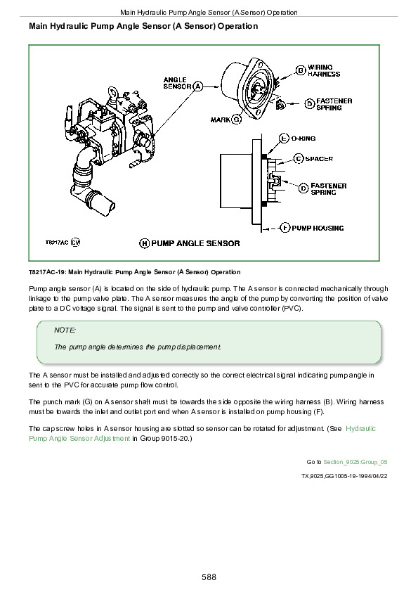
Main Hydraulic Pump Operation…1610
Main Hydraulic Pump Load Sense Operation…1612
Hydraulic Load Sense Generation Circuit Operation…1615
Service Brakes System Operation…1619
Steering and Secondary Steering System Operation…1620
Steering Valve Operation…1623
Secondary Steering Pump Operation…1625
Front Hydraulic System Manifold Operation…1627
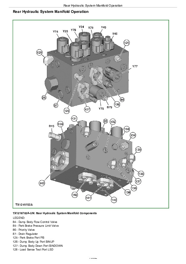
Rear Hydraulic System Manifold Operation…1632
Fan Drive System Operation…1636
Group 10: System Diagrams…1602
Hydraulic Schematic Symbols…1643
Hydraulic System Schematic…1647
Hydraulic System Component Location…1650
Group 15: Diagnostic Information…1602
No Hydraulic Functions…1602
All Hydraulic Functions Slow…1602
Hydraulic Oil Overheats…1602
Main Hydraulic Pump Noisy…1602
Dump Body Will Not Rise…1602
Cab Tilt Manifold Does Not Lift Cab…1602
Hydraulic Fan Motor Not Working…1602
Hydraulic Fan Runs at Full Speed…1602
Poor or No Service Brakes…1680
Service Brake Pads Excessive Wear…1681
Time Between Service Brake Accumulator Charging Cycles Too Short…1682
Service Brake Overheats…1683
Service Brake Cooling Oil Leaking…1684
Service Brake Noise and Vibration…1685
Service Brakes Do Not Fully Release…1686
Slow or No Steering Function…1603
Constant Steering Needed to Maintain Straight Travel…1603
Steering Erratic…1603
Steering Soft or Spongy…1603
Steering Wheel Free Play…1603
Steering Locks Up…1603
Steering Wheel Turns by Itself…1603
Machine Turns in Opposite Direction as Steering Wheel…1603
Machine Turns With Steering Valve in Neutral…1603
Suspension System Not Working…1603
Group 20: Adjustments…1603
Cab Tilt Circuit Bleed Procedure…1715
Group 25: Tests…1603
JT02156A Digital Pressure/Temperature Analyzer Installation…1718
Hydraulic System Warm-Up Procedure…1719
Cycle Time Test…1721
Hydraulic System Deaeration…1723
Main Hydraulic Pump Maximum and Differential Pressure Test and Adjustment…1725
Dump Body Manual Lowering and Bin Tip Circuit Pressure Relieving Procedure…1728
Priority Valve Test…1730
Service Brake Accumulator Pressure Regulator Valve Test Procedure…1731
Service Brake Accumulator Pressure Sensor and Service Brake Accumulator Charge Test Procedure…1732
Front and Rear Service Brake Accumulators Pressure Test Procedure…1733
Service Brake Valve Test Procedure…1734
Electronic Brake Valve (EBV) Test Procedure…1735
Axle Cooling Pump Pressure Test and Flow Test Procedure…1736
Steering Load Sense Relief Valve Test and Adjustment…1737
Steering Cylinder Leakage Test…1740
Hydraulic Fan Circuit Flow Test…1742
Section 9031: Heating and Air Conditioning…1745
Group 05: Theory of Operation…1745
Air Conditioning System Cycle of Operation…1748
Group 15: Diagnostic Information…1745
Air Conditioning System Does Not Operate…1745
Air Conditioning System Does Not Cool Interior of Cab…1745
Air Conditioning System Runs Constantly, Too Cold…1745
Interior Windows Continue to Fog…1745
Heating System Does Not Operate…1745
Heating System Does Not Warm Interior of Cab…1745
Group 25: Tests…1745
R134a Refrigerant Cautions and Proper Handling…1778
Heater and Air Conditioner Operational Checks…1779
Air Conditioning System Test…1783
Operating Pressure Diagnostic Chart…1787
Air Conditioner Freeze Control Sensor Test…1788
Air Conditioner Compressor Clutch Test…1790
Air Conditioner High/Low-Pressure Switch Test…1791
R134a Refrigerant Leak Test…1794
R134a Oil Charge Capacity…1795
R134a Refrigerant Charge Capacity…1796
R134a Refrigerant Hoses and Tubing Inspection…1797

John Deere 260E and 310E Articulated Dump Truck Diagnosis and Test Service Technical Manual (TM13843X19)


INSTANT DOWNLOAD


Posted on

John Deere Tractors Models 500, 504, B550, B554 All Inclusive Service Technical Manual (TM701519)


INSTANT DOWNLOAD


Complete All Inclusive Technical Manual with electrical wiring diagrams for John Deere Tractors 500, 504, B550 and B554 (2WD or MFWD), with workshop information to maintain, diagnose, repair, and rebuild like professional mechanics (Diagnosis, Operation, Tests, Repair, Service, Troubleshooting).

John Deere Tractors Models 500, 504, B550 and B554 workshop technical service manual includes:
* Numbered table of contents easy to use so that you can find the information you need fast.
* Detailed sub-steps expand on repair procedure information
* Numbered instructions guide you through every repair procedure step by step.
* Troubleshooting and electrical service procedures are combined with detailed wiring diagrams for ease of use.
* Notes, cautions and warnings throughout each chapter pinpoint critical information.
* Bold figure number help you quickly match illustrations with instructions.
* Detailed illustrations, drawings and photos guide you through every procedure.
* Enlarged inset helps you identify and examine parts in detail.

PRODUCT DETAILS:
Total Pages: 1,021 pages
File Format: PDF (bookmarked, ToC, Searchable, Printable)
Language: English

tm701519 – John Deere Tractors Models 500, 504, B550, B554 Technical Manual (All Inclusive).pdf
TM701514 TM – All Inclusive 500,504,B550和B554型拖拉机技术手册.pdf
OMSJ16414 Operator’s Manual 500, 504, B550 and B554 Tractor.pdf
OMSJ16415 Operator’s Manual 500, 504, B550 and B554 Tractor.pdf
PC4654 Parts Catalog 500 Tractor (China Edition).pdf
PC4654Z Parts Catalog 500 Tractor (China Edition).pdf

MAIN SECTIONS
Foreword
General
Safety regulations
Technical specifications
Fuel and lubricating oil
Position of serial number plate
Discharge oil and water before servicing
Engine
Engine
Cooling system
Fuel system, air intake and exhaust
Speed control lever
Fuel system
Air intake and exhaust system
Electrical system
Battery and engine
Electrical system components
Wiring harness
Fuses and relays
Electrical schematic
Drive system
Rear PTO shaft
Clutch
Feeder house
Gearbox
Rear differential
Final drive
MFWD
2WD front axle
Steering and braking device
Steering system
Brake
Air brake (optional)
Hydraulic system
Hydraulic pump, oil tank and oil pipe assembly
Lifter
Trailer device
Miscellaneous
Engine hood and shield
Three-point suspension device
Wheel
Front counterweight tray
Cab
Remove and install components
Seat
Safety bracket
Special tools (made by dealers)
Work checking procedures
Engine operational principles, test and adjust
Component locations
Operational principles
Diagnose, test and adjust
Operational principles, test and adjustment of fuel/air intake system
Component locations
Operational principles
Diagnose, test and adjust
Operational principles, test and adjustment of electrical system
Component locations
Operational principles
Diagnose, test and adjust
Circuit diagram
Operational principles, test and adjustment of drive system
Component locations
Operational principles
Diagnose, test and adjust
Operational principles, test and adjustment of steering and braking devices
Component locations
Operational principles
Diagnose, test and adjust
Operational principles, test and adjustment of hydraulic system
Component locations
Operational principles
Diagnose, test and adjust

TABLE OF CONTENTS
Section 10: General…….212
Group 05: Safety regulations…….19
Live With Safety…….24
Recognize Safety Information…….25
Understand Signal Words…….26
Follow Safety Instructions…….27
Prepare for Emergencies…….28
Wear Protective Clothing…….29
Protect Against Noise…….30
Handle Fuel Safely—Avoid Fires…….31
Handle Starting Fluid Safely…….32
Fire Prevention…….33
In Case of Fire…….34
Keep ROPS Installed Properly…….35
Use Foldable ROPS and Seat Belt Properly…….36
Stay Clear of Rotating Drivelines…….37
Use Steps and Handholds Correctly…….39
Read Operator Manuals for ISOBUS Implements…….40
Use Seat Belt Properly…….41
Operating the Tractor Safely…….42
Avoid Backover Accidents…….44
Limited Use in Forestry Operation…….45
Operating the Loader Tractor Safely…….46
Keep Riders Off Machine…….47
Instructional Seat…….48
Use Safety Lights and Devices…….49
Transport Towed Equipment at Safe Speeds…….50
Use Caution On Slopes and Uneven Terrain…….52
Freeing a Mired Machine…….53
Avoid Contact with Agricultural Chemicals…….54
Handle Agricultural Chemicals Safely…….55
Handling Batteries Safely…….57
Avoid Heating Near Pressurized Fluid Lines…….59
Remove Paint Before Welding or Heating…….60
Handle Electronic Components and Brackets Safely…….61
Practice Safe Maintenance…….62
Avoid Hot Exhaust…….63
Clean Exhaust Filter Safely…….64
Work In Ventilated Area…….67
Support Machine Properly…….68
Prevent Machine Runaway…….69
Park Machine Safely…….70
Transport Tractor Safely…….71
Service Cooling System Safely…….72
Service Accumulator Systems Safely…….73
Service Tires Safely…….74
Service Front-Wheel Drive Tractor Safely…….75
Tightening Wheel Retaining Bolts/Nuts…….76
Avoid High-Pressure Fluids…….77
Do Not Open High-Pressure Fuel System…….78
Store Attachments Safely…….79
Dispose of Waste Properly…….80
Use a Safety Chain…….81
Engine Coolant…….82
Produce dealer self-made tools safely…….83
Handle Global Positioning System (GPS) receiver safely…….84
Avoid tractor being out of control…….85
Use Proper Lifting Equipment…….86
Work in Clean Area…….87
Illuminate Work Area Safely…….88
Service Machines Safely…….89
Use Proper Tools…….90
Group 10: Technical specifications…….792
Technical specifications for 2WD model…….96
Technical specifications of mechanical front-wheel drive model…….101
Maximum control force…….106
Minimum turning radius…….107
PTO shaft properties…….108
Traction properties…….109
Properties of hydraulic suspension system…….110
Pouring capacity (L)…….111
Metric bolt and screw torque values…….113
Imperial bolt and screw torque values…….115
Hydraulic system imperial connector torque…….118
Hydraulic system metric connector torque…….119
Clean air filter…….121
Check hose clamps…….122
Clear dust on engine cover and screen…….124
Clean radiator…….125
Check lifter, gearbox and front drive axle oil level…….126
Clean battery…….128
Check neutral start circuit…….129
Tractor operation check…….131
Group 15: Fuel and lubricating oil…….21
Handle fuel safely – Prevent fire…….133
Handle Fluids Safely—Avoid Fires…….134
Handling and Storing Diesel Fuel…….138
Cold Weather Operation…….136
Hot Weather Operation…….137
Diesel Fuel…….138
Lubricity of Diesel Fuel…….140
Testing Diesel Fuel…….141
Fill the fuel tank…….142
Alternative and Synthetic Lubricants…….144
Lubricant Storage…….145
Diesel engine break-in oil…….146
Diesel engine oil…….148
Oil Filters…….150
Heavy Duty Diesel Engine Coolant…….151
Use of Water as Coolant…….152
Liquid coolant conditioner…….153
Transmission and Hydraulic Oil…….154
Use Correct Transmission/Hydraulic Filter Element…….155
MFWD Front Axle Housing Oil…….156
MFWD Wheel Hub Oil…….157
Refuel gearbox…….158
Regularly check and service the gearbox…….159
Lubricating grease (specific applications)…….160
Grease…….161
Group 20: Position of serial number plate…….22
Serial number…….163
Tractor serial number…….164
Tractor machine serial number – 13-digit PIN…….165
Engine serial number…….166
Group 25: Discharge oil and water before servicing…….22
MFWD model front axle oil discharge…….168
MFWD drive transfer case oil discharge…….169
Steering oil tank hydraulic oil discharge…….170
Gearbox oil discharge…….171
Lifter oil discharge…….172
Diesel tank discharge…….173
Coolant discharge…….174
Engine oil discharge…….176
Section 20: Engine…….177
Group 05: Engine…….177
Basic or recommended tools…….179
Technical specifications…….792
Engine maintenance…….181
Remove and install engine…….243
Group 10: Cooling system…….177
Technical specifications…….792
Maintenance of engine water pump…….188
Remove, install and adjust fan drive belt…….189
Remove, check and install radiator…….191
Replace thermostat…….196
Install thermostat…….198
Section 30: Fuel system, air intake and exhaust…….200
Group 05: Speed control lever…….200
Technical specifications…….792
Check and repair engine control mechanism assembly…….203
Adjust foot throttle cable and pedal force…….205
Adjust shut-off cable…….207
Adjust throttle handle…….208
Adjust synchronization of foot throttle pedal and throttle handle…….209
Group 10: Fuel system…….200
General…….212
Technical information…….213
Remove, check and install fuel tank…….214
Replace fuel transfer pump…….219
Replace sediment bowl…….220
Replace sediment bowl assembly…….221
Replace fuel filter and engine oil filter…….223
Bleed air from fuel system…….797
Group 15: Air intake and exhaust system…….200
Technical specifications…….792
Remove, check and install air filter…….228
Remove, check and install muffler…….231
Section 40: Electrical system…….234
Group 05: Battery and engine…….234
Avoid damaging electrical system…….237
Replace battery…….238
Charging battery…….927
Connect battery cables…….240
Remove and install battery…….241
Remove and install engine…….243
Group 10: Electrical system components…….234
Service equipment and tools…….246
Replace water temperature sensor…….247
Replace engine oil pressure sensor…….248
Replace engine speed sensor…….249
Replace fuel volume sensor…….250
Replace keyswitch…….252
Replace warning light switch…….254
Replace high/low beam switch / light switch / work light switch / turn signal light switch / horn switch…….256
Replace brake light switch…….258
Replace gearbox neutral start switch…….259
Replace PTO neutral start switch…….261
Replace horn…….262
Replace flasher…….263
Replace trailer socket (optional)…….264
Replace air pressure alarm switch (optional)…….265
Group 15: Wiring harness…….840
Cable repair pliers…….267
Remove and install electrical connectors…….268
Separate blade terminals from connectors…….269
Replace connector…….270
Install contact…….272
Replace tractor wiring harness…….273
Wiring harness…….840
Group 20: Fuses and relays…….235
Locations of fuses…….280
Fuse specifications and functions…….282
Replace start relays…….283
Group 25: Electrical schematic…….940
Cable color codes…….939
Electrical schematic…….940
Section 50: Drive system…….290
Group 10: Rear PTO shaft…….290
Exploded view of rear PTO control assembly…….294
Exploded view of output driving shaft module…….296
Exploded view of PTO shaft…….298
PTO shaft protection cover assembly…….300
Remove, check and assemble PTO control assembly…….301
Disassemble and check rear PTO shaft assembly…….304
Assemble rear PTO shaft assembly…….314
Group 15: Clutch…….290
Recommended tools…….327
Technical specifications…….792
Remove, check and install clutch assembly…….329
Adjustment of clutch…….331
Disassemble, check and assemble clutch assembly…….333
Adjustment of clutch assembly…….337
Group 20: Feeder house…….290
Technical specifications…….792
Remove and install feeder house…….341
Exploded view of feeder house (2WD)…….344
Exploded view of feeder house (4WD)…….347
Disassemble, check and assemble feeder house…….350
Group 25: Gearbox…….290
Exploded view of gearbox first shaft (MFWD)…….360
Exploded view of gearbox second shaft…….362
Exploded view of gearbox second shaft (MFWD)…….364
Exploded view of control lever assembly and shift fork shaft module…….366
Exploded view of gearbox cover assembly…….368
Remove and install gearbox…….370
Disassemble, check and assemble shift shaft…….373
Disassemble and check first shaft and second shaft…….376
Assemble first shaft and second shaft…….388
Group 30: Rear differential…….291
Technical specifications…….792
General repair procedures – rear differential…….409
Exploded view of rear differential assembly…….410
Remove and install differential assembly…….412
Disassemble, check and assemble differential assembly…….418
Group 35: Final drive…….291
Technical specifications…….792
Exploded view of final drive assembly…….432
Remove and install final drive assembly…….434
Disassemble and check final drive assembly…….439
Assemble final drive assembly…….442
Group 40: MFWD…….291
Technical specifications…….792
Exploded view of drive transfer case and drive shaft (4WD)…….450
Remove, check and install drive transfer case and drive shaft (4WD)…….452
Disassemble, check and assemble drive transfer case (4WD)…….456
Exploded view of bracket and front central drive…….460
Exploded view of front central drive and half shaft housing…….462
Exploded view of front final drive…….464
Remove and check front wheel final drive assembly…….467
Assemble front wheel final drive assembly…….478
Disassemble and check front central drive assembly…….496
Assemble front central drive assembly…….506
Group 45: 2WD front axle…….291
Exploded view of front axle bracket…….523
Exploded view of knuckle and front wheel hub…….525
Exploded view of steering horizontal lever…….527
Remove, check and assemble front axle…….528
Section 60: Steering and braking device…….534
Group 05: Steering system…….534
Technical specifications…….792
Remove and install steering wheel…….537
Remove and install steering column…….538
Remove and install hydraulic steering oil tank…….539
Remove and install hydraulic steering system pipes…….542
Remove and install steering cylinder assembly…….552
Remove and install constant flow pump…….557
Remove and install full hydraulic steering gear…….560
Adjust toe-in (MFWD)…….1035
Adjust front wheel toe-in and wheel tread (2WD model)…….1037
Group 10: Brake…….534
Technical specifications…….792
Remove and install brake pedals…….569
Remove and install braking device…….574
Remove and install handbrake assembly…….581
Adjust brake stroke…….583
Group 10B: Air brake (optional)…….534
Technical requirements…….587
Exploded view of air brake…….588
Exhaust air and discharge water from air reservoir…….590
Remove, check and install valve lever assembly…….591
Remove, check and install cut-off brake valve…….593
Remove, check and install air pipes…….595
Remove, check and install air reservoir…….601
Remove, check and install air reservoir bracket…….603
Repair of compressor…….604
Adjust cut-off brake valve…….605
Section 70: Hydraulic system…….606
Group 05: Hydraulic pump, oil tank and oil pipe assembly…….606
Remove and install gear pump…….610
Remove and install lifter oil tank…….613
Remove and install lifter oil pipes…….616
Group 10: Lifter…….606
Technical specifications…….792
Remove and install lifter assembly…….628
Remove and install lifter parts – lifter upper cover and filter assembly…….630
Remove and install lifter parts – shut-off valve transition plate assembly…….631
Remove and install lifter parts – outer lift arm and lift shaft…….632
Remove and install lifter parts – internal connecting parts…….634
Remove and install lifter parts – cylinder and distributor…….635
Remove and install lifter parts – distributor…….637
Remove and install lifter parts – safety valve and shut-off valve rod…….642
Remove and install lifter parts – lifter oil level gauge…….643
Group 15: Trailer device…….606
Technical specifications…….792
Remove and install trailer device…….646
Section 80: Miscellaneous…….648
Group 05: Engine hood and shield…….648
Remove engine hood…….652
Install engine hood…….655
Remove and install engine hood air spring strut…….658
Remove and install engine hood lock…….659
Remove and install PTO shaft shield…….660
Group 10: Three-point suspension device…….648
Adjust upper lever…….663
Remove and install upper lever assembly…….664
Adjust oblique lever…….666
Remove and install oblique lever…….667
Remove and install lower lever…….670
Adjust external stopper chain assembly…….672
Remove and install external stopper chain…….673
Group 15: Wheel…….648
Technical specifications…….792
Remove and install guide wheels…….679
Remove and install front drive wheels…….680
Remove and install drive wheels…….681
Remove and install rear wheel counterweight…….682
Group 20: Front counterweight tray…….648
Remove, check and install front counterweight tray…….688
Section 90: Cab…….693
Group 05: Remove and install components…….693
Remove and install gantry…….697
Remove and install instrument cover…….700
Remove and install fender and flooring welding assembly…….703
Remove and install boarding step…….706
Remove and install rear-view mirrors…….708
Remove and install cross-beam welding…….710
Group 10: Seat…….693
Remove and install seat…….716
Group 15: Safety bracket…….693
Remove and install safety bracket…….722
Section 99: Special tools (made by dealers)…….724
Group 05: Special tools (made by dealers)…….724
Q22-264 special tool for installing final drive housing shaft sleeve Ⅰ…….727
Q23-83 special tool for installing composite bushes at both ends of first shaft…….729
Q22-4 special shaft for installing clutch assembly…….731
Q23-5 special tool for installing bearing 305…….737
Q23-6 special tool for installing bushes…….739
Q22-56 special tool for installing oil seals…….741
Q22-57 special tool for installing bearings…….742
Q22-105 special tool for installing brake camshaft…….744
Q22-7 special tool for installing reverse gear composite bushes…….746
Q23-3 special tool for installing bearing 6207…….747
Q22-106 special tool for installing bearing 30211 inner ring…….749
Section 210: Work checking procedures…….751
Group 10: Work checking procedures…….751
Information of work checking procedures…….753
Engine oil level and status check…….754
Coolant level and status check…….756
Gearbox oil level check…….758
Lifter oil check…….760
Fan and belt check…….762
Fuel system check…….764
Air intake system check…….766
Electrical system check…….768
Hydraulic system check…….769
Indicator bulb check…….770
Engine start check…….772
Power steering check…….773
Clutch check…….774
Shift lever check…….775
Brake check…….777
Other checks…….779
Section 220: Engine operational principles, test and adjust…….780
Group 05: Component locations…….780
Information of component locations…….1041
Engine external components – left side…….783
Engine external components – right side…….785
Group 10: Operational principles…….780
Information of operational principles…….1044
Operational principles of engine cooling system…….789
Group 15: Diagnose, test and adjust…….780
Technical specifications…….792
Cooling system test…….793
Throttle adjustment…….794
Fan/Generator drive belt adjustment…….795
Bleed air from fuel system…….797
Air filter blockage…….799
Engine cannot start or is difficult to start…….801
Insufficient engine power…….803
Engine emits black smoke…….804
Engine emits blue smoke…….805
Engine emits white smoke…….806
Engine oil pressure is abnormal…….807
Engine oil level rises…….808
Abnormal sound…….809
Water temperature of engine is too high…….810
Engine oil consumption is too much…….811
Excessive vibration…….812
Starter motor failure…….813
Generator failure…….814
Section 230: Operational principles, test and adjustment of fuel/air intake system…….815
Group 05: Component locations…….815
Information of component locations…….1041
Fuel system components…….818
Air intake/exhaust system components…….820
Group 10: Operational principles…….815
Information of operational principles…….1044
Operational principles of fuel system…….823
Operational principles of air intake/exhaust system…….825
Group 15: Diagnose, test and adjust…….815
Diagnostic information…….1053
Fuel/air intake system diagnosis, test and adjustment…….829
Exhaust noise is abnormal…….830
Section 240: Operational principles, test and adjustment of electrical system…….832
Group 05: Component locations…….832
Information of component locations…….1041
Engine electrical components – right side…….836
Engine electrical components – left side…….837
Electrical components of dashboard and main control panel…….838
Wiring harness…….840
Group 10: Operational principles…….832
Information of operational principles…….1044
Fuses…….846
Relays…….848
Operational principles of starting system…….849
Operational principles of battery charging system…….851
Operational principles of lighting system – left/right turn signal light…….853
Operational principles of lighting system – High/Low beam…….855
Operational principles of lighting system – dashboard switch light…….857
Operational principles of lighting system – work lights…….859
Operational principles of lighting system – taillights, front screen lights and brake lights…….861
Operational principles of lighting system – hazard warning light…….864
Operational principles of dashboard system – oil pressure alarm indicator…….866
Operational principles of dashboard system – air brake indicator (optional)…….868
Operational principles of dashboard system – tachometer…….870
Operational principles of dashboard system – fuel gauge…….872
Operational principles of dashboard system – water temperature gauge…….874
Operational principles of horn…….876
Group 15: Diagnose, test and adjust…….832
Diagnostic information…….1053
Cable color table…….882
Starting system test point…….883
Battery charging system test point…….886
Lighting system test points – left/right turn signal light…….888
Lighting system test points – high/low beam…….892
Lighting system test point – dashboard switch light…….896
Lighting system test points – work light…….900
Lighting system test points – taillight, front screen light and brake light…….903
Lighting system test points – hazard warning light…….907
Dashboard system test points – oil pressure alarm indicator…….911
Dashboard system test points – air brake indicator test point (optional)…….914
Dashboard system test points – tachometer…….916
Dashboard system test points – fuel gauge…….918
Dashboard system test points – water temperature gauge…….921
Horn test point…….924
Battery voltage test…….926
Charging battery…….927
Keyswitch test…….928
Fuse test…….930
Neutral start switch test…….931
Hazard alarm switch test…….932
Front floodlight high/low beam switch test…….933
Light switch test…….934
Work light switch test…….935
Turn signal light switch test…….936
Horn switch test…….937
Group 20: Circuit diagram…….833
Cable color codes…….939
Electrical schematic…….940
Section 250: Operational principles, test and adjustment of drive system…….943
Group 05: Component locations…….943
Information of component locations…….1041
Drive system components…….946
Clutch components…….947
Gearbox components…….948
Front drive axle component…….961
Final drive components…….968
Group 10: Operational principles…….943
Information of operational principles…….1044
Operational principles of clutch…….972
Operational principles of gearbox…….974
Operational principles of final drive…….979
Operational principles of rear PTO shaft…….981
Operational principles of drive transfer case transmission…….983
Operational principles of MFWD…….985
Group 15: Diagnose, test and adjust…….943
Diagnostic information…….1053
Isolate defective components…….990
Clutch slippage…….992
Clutch cannot be disengaged completely…….993
Clutch engagement…….994
Clutch cannot be disengaged…….995
Clutch pedal does not return…….996
Power is transmitted unstably or unsteadily…….997
Gearbox oil level is low (serious oil leakage)…….998
Gear bumps, shifting is difficult or fails to engage…….999
Gearbox fails to stay at required gear position…….1000
PTO shaft generates much noise…….1001
PTO shaft is difficult to engage…….1002
PTO shaft fails to stay at engaged status…….1003
Differential generates much noise…….1004
Section 260: Operational principles, test and adjustment of steering and braking devices…….1005
Group 05: Component locations…….1005
Information of component locations…….1041
Steering system components…….1008
Braking system components…….1011
Group 10: Operational principles…….1005
Information of operational principles…….1044
Operational principles of hydraulic steering system…….1017
Operational principles of braking system…….1020
Group 15: Diagnose, test and adjust…….1005
Diagnostic information…….1053
Isolate defective components – steering system…….1028
It is difficult or fails to steer…….1029
Steering cylinder leakage test…….1030
Isolate defective components – brake…….1031
Braking is not stable…….1032
Isolate defective components – air brake…….1033
Air pressure alarm switch light is lit…….1034
Adjust toe-in (MFWD)…….1035
Adjust front wheel toe-in and wheel tread (2WD model)…….1037
Section 270: Operational principles, test and adjustment of hydraulic system…….1039
Group 05: Component locations…….1039
Information of component locations…….1041
Lifter assembly…….1042
Group 10: Operational principles…….1039
Information of operational principles…….1044
Operational principles of hydraulic system…….1045
Group 15: Diagnose, test and adjust…….1039
Diagnostic information…….1053
Preliminary checks of hydraulic system…….1054
Entire hydraulic system is not working / hydraulic oil pump does not supply oil…….1055
Insufficient oil supply from oil pump…….1056
Oil pump pressure is too high…….1057
Too much noise is generated when oil pump works…….1058
Lifter does not lift or lifting speed is too slow…….1059

John Deere Tractors Models 500, 504, B550, B554 All Inclusive Service Technical Manual (TM701519)


INSTANT DOWNLOAD


Posted on

John Deere 493D Feller-Buncher Repair Service Manual (TM1415)


INSTANT DOWNLOAD


Complete service repair manual with Electrical Wiring Diagrams for John Deere 493D Feller-Buncher, with all the technical information to maintain, diagnose, repair, and rebuild like professional mechanics.

John Deere 493D Feller-Buncher workshop service repair manual includes:
* Numbered table of contents easy to use so that you can find the information you need fast.
* Detailed sub-steps expand on repair procedure information
* Numbered instructions guide you through every repair procedure step by step.
* Troubleshooting and electrical service procedures are combined with detailed wiring diagrams for ease of use.
* Notes, cautions and warnings throughout each chapter pinpoint critical information.
* Bold figure number help you quickly match illustrations with instructions.
* Detailed illustrations, drawings and photos guide you through every procedure.
* Enlarged inset helps you identify and examine parts in detail.

TM1415 – John Deere 493D Feller-Buncher Technical Manual.pdf

This is TM-1415 493D Feller-Buncher.
The pages are dated (Jun-88). Listed below is a brief explanation.
This manual is to be used with:
TM-1390 490D Excavator Repair, and
TM-1389 490D Excavator Operation and Tests
Both Feller Buncher repair and operation/test information are in this manual.

PRODUCT DETAILS:
Total Pages: 168 pages
File Format: PDF
Language: English

TABLE OF CONTENTS
SECTION I —GENERAL INFORMATION
SECTION 01—TRACKS
SECTION 05—ENGINE AUXILIARY SYSTEMS
SECTION 16—ELECTRICAL
Group 1674—Wiring Harness and Switches Controller Switches
SECTION 18—OPERATOR’S STATION
SECTION 33—EXCAVATOR
SECTION 9005—OPERATIONAL CHECK-OUT PROCEDURE
SECTION 9015—ELECTRICAL SYSTEM
SECTION 9020—POWER TRAIN
SECTION 9025—HYDRAULIC SYSTEM

John Deere 493D Feller-Buncher Repair Service Manual (TM1415)


INSTANT DOWNLOAD


Posted on

John Deere 490E Excavators Diagnostics Technical Manual (TM1504)


INSTANT DOWNLOAD


Complete Diagnostics, Operation and Test manual with electrical wiring diagrams for John Deere 490E Excavator, with all the service information to maintain, diagnose, and rebuild like professional mechanics.

John Deere 490E Excavator workshop Operation and Test manual includes:
* Numbered table of contents easy to use so that you can find the information you need fast.
* Detailed sub-steps expand on repair procedure information
* Numbered instructions guide you through every repair procedure step by step.
* Troubleshooting and electrical service procedures are combined with detailed wiring diagrams for ease of use.
* Notes, cautions and warnings throughout each chapter pinpoint critical information.
* Bold figure number help you quickly match illustrations with instructions.
* Detailed illustrations, drawings and photos guide you through every procedure.
* Enlarged inset helps you identify and examine parts in detail.

TM1504 – John Deere 490E Excavator Technical Manual – Operation and Test.PDF

PRODUCT DETAILS:
Total Pages: 860 pages
File Format: PDF (bookmarked, ToC, Searchable, Printable, high quality)
Language: English

MAIN SECTIONS
Foreword
General Information
Safety
General Specifications
Torque Values
Fuels And Lubricants
Operational Checkout
Operational Checkout Procedure
Engine
Theory Of Operation
System Operational Checks
Diagnostic Information
Adjustments
Tests
Electrical System
System Information
System Diagrams
References
Power Train
Theory Of Operation
System Operational Checks
Diagnostic Information
Adjustments
Tests
Hydraulic System
Theory Of Operation
System Operational Checks
Diagnostic Information
Adjustments
Tests

TABLE OF CONTENTS
Section 9000: General Information….14
Group 01: Safety….14
Follow Safe Procedures….17
Prepare for Emergencies….18
Prevent Acid Burns….19
Handle Chemical Products Safely….21
Handle Fluids Safely-Avoid Fires….22
Avoid High-Pressure Fluids….23
Warn Others of Service Work….24
Support Machine Properly….25
Operate Only from Operator's Seat….26
Park Machine Safely….27
Stay Clear of Moving Parts….28
Avoid Power Lines….29
Use Handholds and Steps….30
Keep Riders Off Machine….31
Move and Operate Machine Safely….32
Wear Protective Clothing….33
Protect Against Flying Debris….34
Protect Against Noise….35
Illuminate Work Area Safely….36
Service Machines Safely….37
Remove Paint Before Welding or Heating….38
Avoid Heating Near Pressurized Fluid Lines….39
Beware of Exhaust Fumes….40
Use Proper Lifting Equipment….41
Service Cooling System Safely….42
Dispose of Waste Properly….43
Work in a Clean Area….44
Use Tools Properly….45
Replace Safety Signs….46
Live With Safety….47
Group 02: General Specifications….14
490E….15
490E Drain And Refill Capacities….15
Group 03: Torque Values….15
Unified Inch Bolt and Cap Screw Torque Values….54
Metric Bolt and Cap Screw Torque Values….55
Additional Metric Cap Screw Torque Values….56
Service Recommendations for O-Ring Boss Fittings….58
Service Recommendations for Flat Face O-Ring Seal Fittings….60
Service Recommendations for 37° Flare and 30° Cone Seat Connectors….62
Service Recommendations For Flared Connections-Straight or Tapered Threads….64
Service Recommendations For Inch Series Four Bolt Flange Fittings….66
Service Recommendations for Metric Series Four Bolt Flange Fitting….68
Group 04: Fuels And Lubricants….15
Fuel Specifications….71
Engine Oil….72
Hydraulic Oil….74
Swing Gearbox, Propel Gearbox and Pump Gearbox Oils….75
Track Roller, Front Idler, And Carrier Roller Oil….76
Track Adjuster, Working Tool Pivot, Swing Bearing, And Swing Bearing Gear Grease….77
Section 9005: Operational Checkout….85
Group 10: Operational Checkout Procedure….78
Operational Checkout Record Sheet-490E….82
Operational Checkout….85
Section 9010: Engine….133
Group 05: Theory Of Operation….133
4045 John Deere Engine-Use CTM8….133
General Engine Description….136
Engine-Sectional View….138
Fan Drive Operation….140
Engine Speed Control System Operation….141
Group 10: System Operational Checks….133
4045 John Deere Engine-Use CTM8….133
Engine Operational Checks….145
Group 15: Diagnostic Information….133
4045 John Deere Engine-Use CTM8….133
Diagnose Engine Malfunctions….162
Group 20: Adjustments….133
4045 John Deere Engine-Use CTM8….133
JT05801 Clamp-On Electronic Tachometer Installation….795
Engine Speed And Control Linkage Adjustment….401
Group 25: Tests….133
4045 John Deere Engine-Use CTM8….133
Fuel Line Leakage Test….182
Air Filter Restriction Indicator Switch Test….183
Air Intake System Leakage Test….185
Radiator Air Flow Test….187
JT05529 Air Flow Meter Test Record….189
Section 9015: Electrical System….191
Group 05: System Information….191
Visually Inspect Electrical System….195
Electrical Circuit Malfunctions….196
High Resistance Circuit….198
Open Circuit….200
Grounded Circuit….202
Shorted Circuit….204
Multimeter….206
Seven Step Electrical Test Procedure….207
Wiring Diagram And Schematic Information….209
Reading A System Functional Schematic….231
Reading A Wiring Diagram….212
Electrical Schematic Symbols….214
Group 10: System Diagrams….191
Replacing Fuses….218
Fuse (Blade-Type) Color Codes….219
Fuse Specifications….220
Switch Specifications….222
Component Identification Table….223
Wiring And Schematic Diagrams Legend….225
Component Location Diagram….230
System Functional Schematic….231
Engine Harness (W5) Wiring Diagram….233
Cab Harness (W6) Wiring Diagram….234
Power Circuit Operational Information….235
Power Circuit Theory Of Operation….236
Power Circuit Schematic….237
Charging Circuit Operational Information….243
Charging Circuit Theory Of Operation….244
Charging Circuit Schematic….245
Windshield Wiper And Washer Circuit Operational Information….250
Windshield Wiper And Washer Circuit Theory Of Operation….251
Windshield Wiper And Washer Circuit Schematic….252
Switch Panel 1 Circuit Operational Information….258
Switch Panel 1 Theory Of Operation….259
Switch Panel 1 Circuit Schematic….260
Switch Panel 2 Circuit Operational Information….263
Switch Panel 2 Theory Of Operation….264
Switch Panel 2 Circuit Schematic….265
Light Circuit Operational Information….268
Light Circuit Theory Of Operation….269
Light Circuit Schematic….270
Horn, Dome Light, Cigar Lighter And Heater Circuits Operational Information….275
Horn, Dome Light, Cigar Lighter And Heater Circuits Theory Of Operation….276
Horn, Dome Light, Cigarette Lighter And Heater Circuits Schematic….277
Monitor Circuit Specifications….283
Monitor Circuit Operational Information….284
Monitor Circuit Theory Of Operation….285
Monitor Circuit Schematic….286
Auto Idle Circuit Operational Information….302
Auto Idle Circuit Theory Of Operation….303
Auto Idle Circuit Schematic….305
Warm-Up Circuit Operational Information….315
Warm-Up Circuit Theory Of Operation….316
Hydraulic Warm-Up Circuit Schematic….317
Pump And Valve Controller Circuit Operational Information….327
Pump And Valve Controller Circuit Theory Of Operation….328
Pump And Valve Controller Circuit Schematic….329
Engine Controller Circuit Operational Information….353
Engine Controller Circuit Theory Of Operation….354
Engine Controller Circuit Schematic….356
Start Aid And Travel Alarm Circuit Operational Information….365
Start Aid And Propel Alarm Circuit Theory Of Operation….366
Start Aid And Propel Alarm Circuit Schematic….367
Group 20: References….192
Monitor And Switch Panels….379
Monitor Panel….381
Switch Panel 1….382
Switch Panel 2….546
Resetting Engine Controller (EC)….385
Electrical Component Identification….386
Alternator Voltage Output Test-Delco….388
Alternator Operation-40 Amp Delco Remy….389
Replacing Batteries….391
Battery Operation….392
Diagnose Battery Malfunctions….393
Check Battery Electrolyte Level And Terminals….394
Procedure For Testing Batteries….397
Using Booster Batteries-24 Volt System….399
Engine Speed And Control Linkage Adjustment….401
Electronic Control Bypass Procedure….404
Hydraulic Pump Angle Sensor (A Sensor) Mechanical Check Diagnostic Procedure….715
Hydraulic Pump Angle Sensor (A Sensor) Adjustment….409
Troubleshooting Pump And Valve Controller (PVC)….700
Troubleshooting Engine Controller (EC)….701
Engine Control Sensor (EC Sensor) Harness Test….413
Connecting Engine Controller (EC) And Pump And Valve Controller (PVC) Harness Connector….417
Disconnect Tab Retainer Connectors….418
Disconnecting Spring Wire Retainer Connectors….419
Connector Pin Location And Numbers….420
Section 9020: Power Train….421
Group 05: Theory Of Operation….421
Power Train Components….424
Propel System Operation….425
Propel Pilot Circuit Operation….571
Propel Pilot Controller Operation-Neutral….583
Propel Pilot Check Valve Block Operation-Forward….430
Propel Control Valve Operation….432
Variable Pressure Compensator Valve Operation….434
Propel Proportional Solenoid Valve Operation….579
Propel Speed Control System Operation….438
Propel Speed Change Solenoid Valve Operation….440
Rotary Manifold Operation….442
Propel Brake Valve Operation….443
Propel Brake Pressure Reducing Valve Operation….445
Counterbalance Valve Operation-Neutral….447
Counterbalance Valve Operation-Propel….448
Counterbalance Valve Operation-Braking….450
Propel Motor Crossover Relief Valve Operation….451
Propel Motor Operation….453
Propel Speed Operation-Super Low And Normal….455
Propel Motor Operation-Max. Speed….457
Charge Valve Operation-Normal Maximum Speed….459
Charge Valve Maximum Speed Operation-Braking….460
Propel Gearbox Operation….461
Track Adjuster Operation….463
Group 10: System Operational Checks….421
Power Train Operational Checks….475
Group 15: Diagnostic Information….421
Diagnose Undercarriage Components Malfunctions….488
Diagnose Propel System Malfunctions….490
Measure Track Chain Bushing Wear….498
Measure Track Chain Pitch….499
Measure Track Chain Link Wear….500
Measure Track Shoe Grouser Wear….501
Measure Lower Track Roller Wear….502
Measure Front Idler Wear….503
Measure Upper Track Roller Wear….504
Propel System Component Location….505
Group 20: Adjustments….422
Adjust Track Sag….508
Propel Speed Cycle Time….510
Group 25: Tests….422
JT07058 Diagnostic Computer Operating Procedure….760
JT07059 Diagnostic Computer Function….767
JT05801 Clamp-On Electronic Tachometer Installation….795
JT05800 Digital Thermometer Installation….796
Hydraulic System Warm-Up Procedure….797
Propel Motor Start-Up Procedure….521
Engine Speed Programming Procedure After Battery Disconnection….803
Propel Motor Crossover Relief Valve Test And Adjustment….523
Propel Speed Change Solenoid Valve Test And Adjustment….527
Propel Proportional Solenoid Valve Test And Adjustment….529
Propel Motor Operating Leakage Test….532
Swing Bearing Wobble Test….534
Section 9025: Hydraulic System….542
Group 05: Theory Of Operation….535
Hydraulic System….542
Control Systems Operation….544
Switch Panel 2….546
Engine (EC), Pump And Valve (PVC) Controllers….548
Engine Control Circuit….550
Engine Power Modes….552
Hydraulic System Block Diagram….553
Load Sense System-Control Valves In Neutral….555
Load Sense System-Single Function Actuated….557
Load Sense System-Function Held Over Relief….559
Pump Control-Speed Sensing….560
Flow Dividing Control System….562
Work Mode Chart….564
Propel Speed Control System….565
Swing Brake Release Circuit Operation….567
Swing Stop Cushion Valve Circuit Operation….568
Warm-Up Control Circuit….569
Pilot Circuit Operation….571
Pilot Pump Operation….573
Pilot Filter Operation….574
Solenoid Valve Assembly Operation….575
Pilot Pressure Regulating Valve Operation….577
Pilot Pressure Reducing Valve Operation….578
Proportional Solenoid Valve Operation….579
Pilot Shut-Off Valve Operation….581
Pilot Controller Operation-Neutral….583
Pilot Controller Operation-Metering….584
Pilot Controller Operation-Full Stroke….585
Pilot Operation Of Main Control Valve….586
Dig Function Pilot Controller Check Valve Operation….588
Flow Regulator Valve Operation….589
Warm-Up Circuit Operation….591
Main Hydraulic Pump Operation….592
Main Hydraulic Pump Displacement Solenoid Valves Operation….594
Main Hydraulic Pump Control Operation….595
Main Hydraulic Pump Operation-Maximum Displacement….597
Main Hydraulic Pump Operation-Minimum Displacement….599
Main Hydraulic Pump Angle Sensor (A Sensor) Operation….601
Main Hydraulic Pump And Drive Gearbox-Serial No. (025000-)….602
Main Control Valve Operation….603
Control Valve Inlet Section Operation….605
Surge Relief Valve Operation (Serial No. -024999) System Relief Valve Operation (Serial No. 025000- )….607
System Relief Valve And Unloading Valve Operation-Neutral….609
System Relief Valve And Unloading Valve Operation-Activated….611
Circuit Relief Valve Operation….613
Differential Pressure Sensor Operation….615
Variable Pressure Compensator Valves Operation….617
Auxiliary Valve Operation….619
Arm, Boom, And Bucket Valve Operation….621
Anti-Drift Valve Operation….623
Swing Valve Operation….625
Shuttle Valve Operation….626
Combined Function Operation….628
Swing Motor And Brake Operation….630
Swing Motor Cover Operation-Start Of Swing….632
Swing Motor Cover Operation-Normal Swing….634
Swing Motor Cover Operation-Stopping….636
Swing Brake Release Solenoid Valve Operation….638
Swing Stop Cushion Valve Operation….640
Swing Stop Cushion Valve Operation-Swinging….642
Swing Gearbox Operation….643
Cylinder Operation….645
Return Filter Operation….646
Suction Screen Operation….647
Oil Cooler Operation….648
Pump Inlet And Delivery Circuits Operation….649
Return Circuit Operation….651
Drain Circuit Operation….652
Group 10: System Operational Checks….537
Hydraulic Operational Checks….670
Group 15: Diagnostic Information….537
Diagnostic Procedure….691
JT07058 Diagnostic Computer Operating Procedure….760
JT07059 Diagnostic Computer Function….767
Troubleshooting Differential Pressure Sensor (DP Sensor)….699
Troubleshooting Pump And Valve Controller (PVC)….700
Troubleshooting Engine Controller (EC)….701
Troubleshooting Engine Speed Sensor (N Sensor)….702
Troubleshooting Pump Displacement Angle Sensor (A Sensor)….703
Troubleshooting Pressure Sensor (P Sensor)….704
Troubleshooting Engine Control Sensor (EC Sensor)….705
Troubleshooting Hydraulic Oil Temperature Sensor (T Sensor)….706
Troubleshooting Boom Up Pilot Pressure Sensor (BPI Sensor)-Serial No. (025000- )….707
Troubleshooting Arm In Pressure Sensor (ABP Sensor)-Serial No. (025000- )….708
Troubleshooting Pump Displacement Solenoid Valve (PDSV)….709
Troubleshooting Proportional Solenoid Valve….710
Troubleshooting Propel Speed Change Solenoid Valve….711
Troubleshooting Swing Brake Release Solenoid Valve….712
Troubleshooting Swing Stop Cushion Valve….713
Troubleshooting Engine Control Motor (EC Motor)….714
Hydraulic Pump Angle Sensor (A Sensor) Mechanical Check Diagnostic Procedure….715
Introduction To Flow Charts….717
Diagnose Hydraulic System Malfunctions….730
Diagnose Pilot Circuit Malfunctions….735
Diagnose Dig Circuit Malfunctions….737
Diagnose Swing Circuit Malfunctions….743
Pilot Circuit Component Location….749
Hydraulic System Component Location….750
Pilot System SAE Pattern….751
Pilot System John Deere Pattern….752
Group 20: Adjustments….538
Pilot Shut-Off Valve Linkage Adjustment….756
Group 25: Tests….538
JT07058 Diagnostic Computer Operating Procedure….760
JT07058 Diagnostic Computer Initial Setup….762
Connecting JT07058 Diagnostic Computer To Machine….764
Begin JT07058 Diagnostic Computer Function….765
JT07059 Diagnostic Computer Function….767
Retry Procedure A….769
Retry Procedure B….771
Self Diagnostic Function Fault Codes For Engine Controller (EC)….773
Self Diagnostic Function Fault Codes For Pump And Valve Controller (PVC)….775
Monitor Data Function Display List And Description….778
Component Abbreviations And Location….785
Cross Reference To Monitor Data Function And Display Symbol….787
Reading Fault Codes Without JT07058 Diagnostic Computer….789
Reading Fault Codes With JT07058 Diagnostic Computer….791
Monitor Data Function Worksheet-490E….792
Example Of Monitor Data Function Worksheet….794
JT05801 Clamp-On Electronic Tachometer Installation….795
JT05800 Digital Thermometer Installation….796
Hydraulic System Warm-Up Procedure….797
Hydraulic Pump Start-Up Procedure….799
Swing Motor Start-Up Procedure….800
Swing Gearbox Start-Up Procedure….801
Hydraulic Oil Filter Inspection Procedure….802
Engine Speed Programming Procedure After Battery Disconnection….803
Hydraulic Oil Cleanup Procedure Using Portable Filter Caddy….804
Cycle Time Test….806
Proportional Solenoid Valve Harness Test….809
Swing Brake Solenoid Valve Harness Test….810
Pump Displacement Solenoid Valve Harness Test….812
Swing Stop Cushion Valve Harness Test….814
Engine Control Motor (EC Motor) Harness Test….816
Differential Pressure Sensor Voltage Test And Adjustment….818
Engine Control Sensor (EC Sensor) Test….821
Miscellaneous Harness Test….824
Pilot Pressure Regulating Valve Test And Adjustment….826
Pilot Pressure Reducing Valve Test And Adjustment….830
Surge Relief Valve Test And Adjustment-Serial No. ( -024999)….833
System Relief Valve Test And Adjustment-(Serial No. -024999)….837
System Relief Valve Test And Adjustment-(Serial No. 025000- )….840
Circuit Relief Valve Test And Adjustment….844
Proportional Solenoid Valve (PSV) Test And Adjustment….848
Swing Motor Crossover Relief Valve Test And Adjustment….852
Hydraulic Pump Flow Test….856
Engine Power Or Hydraulic Pump Test Using Flow Meter Method….860
Pilot Pump Flow Test….866
Arm, Boom, And Bucket Cylinder Drift Test….869
Swing Motor Leakage Test….872
Oil Cooler Flow And Pressure Drop Test….875

John Deere 490E Excavators Diagnostics Technical Manual (TM1504)


INSTANT DOWNLOAD


Posted on

John Deere 490E Excavator Service Repair Manual (TM1505)


INSTANT DOWNLOAD


Complete service repair manual for John Deere 490E Excavator, with all the service information to maintain, repair, and rebuild like professional mechanics.

John Deere 490E Excavator workshop service & repair manual includes:
* Numbered table of contents easy to use so that you can find the information you need fast.
* Detailed sub-steps expand on repair procedure information
* Numbered instructions guide you through every repair procedure step by step.
* Notes, cautions and warnings throughout each chapter pinpoint critical information.
* Bold figure number help you quickly match illustrations with instructions.
* Detailed illustrations, drawings and photos guide you through every procedure.
* Enlarged inset helps you identify and examine parts in detail.

TM1505 – John Deere 490E Excavator Technical Manual – Repair.PDF
ctm104 English – 4.5L AND 6.8L DIESEL ENGINES (BASE ENGINE) -: (WORLDWIDE EDITION) CTM
CTM8 English – Series 300 3029 (S.N. -499999), 4039, 4045, 6059 and 6068 Diesel Engines CTM

PRODUCT DETAILS:
Total Pages: 664 pages
File Format: PDF (bookmarked, ToC, Searchable, Printable, high quality)
Language: English

TABLE OF CONTENTS
Section 00: General Information…14
Group 0001: Safety…14
Follow Safe Procedures…17
Prepare for Emergencies…18
Prevent Acid Burns…19
Handle Chemical Products Safely…21
Handle Fluids Safely-Avoid Fires…22
Avoid High-Pressure Fluids…23
Warn Others of Service Work…24
Support Machine Properly…25
Operate Only from Operator’s Seat…26
Park Machine Safely…27
Stay Clear of Moving Parts…28
Avoid Power Lines…29
Use Handholds and Steps…30
Keep Riders Off Machine…31
Move and Operate Machine Safely…32
Wear Protective Clothing…33
Protect Against Flying Debris…34
Protect Against Noise…35
Illuminate Work Area Safely…36
Service Machines Safely…37
Remove Paint Before Welding or Heating…38
Avoid Heating Near Pressurized Fluid Lines…39
Beware of Exhaust Fumes…40
Use Proper Lifting Equipment…41
Service Cooling System Safely…42
Dispose of Waste Properly…43
Work in a Clean Area…44
Use Tools Properly…45
Replace Safety Signs…46
Live With Safety…47
Group 0002: General Specifications…670
490E…15
490E Drain And Refill Capacities…15
Group 0003: Torque Values…15
Unified Inch Bolt and Cap Screw Torque Values…54
Metric Bolt and Cap Screw Torque Values…55
Additional Metric Cap Screw Torque Values…56
Service Recommendations for O-Ring Boss Fittings…58
Service Recommendations for Flat Face O-Ring Seal Fittings…60
Service Recommendations for 37° Flare and 30° Cone Seat Connectors…62
Service Recommendations For Flared Connections-Straight or Tapered Threads…64
Service Recommendations For Inch Series Four Bolt Flange Fittings…66
Service Recommendations for Metric Series Four Bolt Flange Fitting…68
Group 0004: Fuels and Lubricants…15
Fuel Specifications…670
Engine Oil…72
Hydraulic Oil…74
Swing Gearbox, Propel Gearbox and Pump Gearbox Oils…75
Track Roller, Front Idler, And Carrier Roller Oil…76
Track Adjuster, Working Tool Pivot, Swing Bearing, And Swing Bearing Gear Grease…77
Section 01: Tracks…78
Group 0130: Track System…78
Service Equipment and Tools…634
Other Material…635
Specifications…670
Measure Lower Track Roller Wear…83
Remove and Install Lower Track Roller…84
Disassemble and Assemble Lower Track Roller…86
Test Lower Track Roller for Oil Leakage…89
Measure Upper Track Roller Wear…90
Remove and Install Upper Track Roller…91
Disassemble and Assemble Upper Track Roller…93
Inspect Metal Face Seals…153
Measure Track Shoe Grouser Wear…98
Remove and Install Track Shoe…99
Measure Track Chain Link Wear…101
Measure Track Chain Bushing Wear…102
Measure Track Chain Pitch…103
Remove Track Chain…104
Install Track Chain…107
Disassemble and Assemble Track Chain…110
Disassemble and Assemble Track Chain to Replace Broken Part…112
Adjust Track Sag…115
Remove and Install Sprocket…117
Measure Front Idler Wear…119
Remove and Install Front Idler…120
Disassemble Front Idler…121
Assemble Front Idler…123
Test Front Idler for Oil Leakage…125
Remove and Install Track Adjuster Cylinder and Recoil Spring…127
Disassemble and Assemble Track Adjuster Recoil Spring…130
Disassemble and Assemble Track Adjuster Cylinder…135
Section 02: Axles and Suspension Systems…138
Group 0250: Axle Shaft, Bearings, and Reduction Gears…138
Service Equipment and Tools…634
Other Material…635
Specifications…670
Towing Machine…143
Remove and Install Propel Gearbox…145
Disassemble Propel Gearbox…148
Inspect Metal Face Seals…153
Disassemble and Assemble First Planet Carrier…155
Disassemble and Assemble Second Planet Carrier…156
Assemble Propel Gearbox…157
Group 0260: Hydraulic System…138
Service Equipment and Tools…634
Other Material…635
Specifications…670
Remove and Install Propel Motor and Brake…166
Propel Motor Start-Up Procedure…169
Disassemble Propel Motor and Brake…170
Assemble Propel Motor and Brake…174
Disassemble and Assemble Propel Motor Brake Valve Housing…179
Remove and Install Rotary Manifold…190
Disassemble and Assemble Rotary Manifold…194
Rotary Manifold Air Test…197
Section 04: Engine…198
Group 0400: Removal and Installation…198
4045 John Deere Engine-Use CTM8…198
Special or Essential Tools…459
Service Equipment and Tools…634
Other Material…635
Specifications…670
Remove Engine…206
Install Engine…211
Remove and Install Oil Pan…216
Removing DB4 Fuel Injection Pump…219
Installing DB4 Fuel Injection Pump…223
JT07158 TIME TRAC TIME TRAC is a registered trademark of the Stanadyne Automotive Corp. Installation…198
Bleed Fuel System…229
Adjust Engine Valve Lash (Clearance)…230
Remove and Install Starter…233
Section 05: Engine Auxiliary Systems…235
Group 0505: Cold Weather Starting Aids…235
Other Material…635
Specifications…670
Remove and Install Starting Aid Solenoid and Nozzle…239
Remove and Install Engine Coolant Heater…241
Group 0510: Cooling System…235
Specifications…670
Remove and Install Fan, Shroud, and Guards…245
Remove and Install Radiator…247
Remove and Install Fan Belt…250
Group 0515: Speed Controls…235
Service Equipment and Tools…634
Other Material…635
Specifications…670
Remove and Install Engine Speed and Control Linkage…255
Engine Speed and Control Linkage Adjustment…257
Remove and Install Engine Control (EC) Motor and Sensor…260
Disassemble and Assemble Engine Control (EC) Motor and Sensor…262
Group 0520: Intake System…235
Special or Essential Tools…459
Service Equipment and Tools…634
Specifications…670
Remove and Install Air Cleaner…269
Air Intake System Leakage Test…270
Group 0560: External Fuel Supply Systems…235
Other Material…635
Specifications…670
Remove and Install Fuel Tank…274
Remove and Install Water Separator Filter…276
Disassemble and Assemble Water Separator Filter…277
Section 07: Dampener Drive (Flex Coupling)…279
Group 0752: Elements…279
Specifications…670
Remove and Install Dampener Drive (Flex Coupling)…282
Section 16: Electrical System…287
Group 1671: Batteries, Support, and Cables…287
Service Equipment and Tools…634
Specifications…670
Handle Batteries Safely…292
Procedure for Testing Batteries…293
Checking Electrolyte Specific Gravity…294
Check Battery Electrolyte Level and Terminals…297
Using Booster Batteries-24-Volt System…300
Charge Battery…302
Batteries Remove and Install…305
Adding 12-Volt Accessories…307
Group 1672: Alternator, Regulator, and Charging System Wiring…287
Alternators and Starting Motors-Use CTM77…309
Specifications…670
Remove and Install Alternator…311
Group 1674: Wiring Harness and Switches…287
Special or Essential Tools…459
Front Chassis Electrical Component Identification…315
Cab Electrical Component Identification…317
Hydraulic Electrical Component Identification…320
Engine Electrical Component Identification…322
Connecting Engine Controller (EC) and Pump and Valve Controller (PVC) Harness Connector…352
Disconnecting Spring Wire Retainer Connectors…325
Disconnecting Tab Retainer Connectors…326
Replacing Fuses…327
Fuse (Blade-Type) Color Codes…330
Remove and Install Cab Ground Straps…331
Remove and Install Starter Switch…332
Remove and Install Dome Light Switch…334
Remove and Install Propel Alarm Cancel Switch and Start Aid Switch…335
Replace DEUTSCH DEUTSCH is a trademark of the Deutsch Co. Connectors…287
Install DEUTSCH DEUTSCH is a trademark of the Deutsch Co. Contact…288
Replace WEATHER PACK WEATHER PACK is a trademark of Packard Electric Connector…288
Install WEATHER PACK WEATHER PACK is a trademark of Packard Electric Contact…288
Remove Connector Body From Blade Terminals…345
Group 1675: System Controls…288
Welding on Machine…435
Connecting Engine Controller (EC) and Pump and Valve Controller (PVC) Harness Connector…352
Remove and Install Pump and Valve Controller (PVC)…353
Remove and Install Monitor Controller…355
Group 1676: Instruments and Indicators…288
Replace Monitor Panel Bulbs…357
Remove and Install Monitor Panel…358
Remove and Install Switch Panel 1…360
Remove and Install Hour Meter, Coolant Temperature and Fuel Level Gauges…361
Replace Switch Panel 2 Bulb…363
Remove and Install Switch Panel 2…364
Section 17: Frame or Supporting Structure…366
Group 1740: Frame Installation…366
Specifications…670
Welding on Machine…435
Welding Repair of Major Structure…372
Group 1749: Chassis Weights…366
Service Equipment and Tools…634
Specifications…670
Remove and Install Counterweight…377
Section 18: Operator’s Station…379
Group 1800: Removal and Installation…379
Specifications…670
Remove and Install Cab…382
Group 1810: Operator Enclosure…379
Service Equipment and Tools…634
Other Material…635
Remove and Install Windowpane and Two Piece Molding…390
Remove and Install Windowpane and One Piece Molding…392
Remove and Install Sliding Windows…393
Windowpane Dimensions…395
Group 1821: Seat and Seat Belt…379
Specifications…670
Remove and Install Seat…399
Disassemble and Assemble Seat (Early Machine)…401
Disassemble and Assemble Seat Stand (Early Machine)…403
Group 1830: Heating and Air Conditioning…379
Remove and Install Blower Motor…408
Remove and Install Heater Core and Blower Motor Relay…410
Section 20: Safety and Convenience…411
Group 2004: Horn and Warning Devices…411
Remove and Install Travel Alarm…413
Changing Travel Alarm Volume…414
Section 33: Excavator…416
Group 3302: Bucket…416
Specifications…670
Replacing Bucket Teeth…421
Replacing Bucket Tooth Tip-Heavy-Duty Bucket…423
Remove and Install Tooth Shank…425
Remove and Install Bucket and Linkage…428
Adjust Bucket Linkage…433
Welding on Machine…435
Replace Welded Bucket Cutting Edges…437
Repair Cracked Cutting Edge…438
Group 3340: Frames…416
Service Equipment and Tools…634
Specifications…670
Remove and Install Arm…443
Remove and Install Boom…449
Inspect Arm and Boom Pins and Bushings…454
Remove and Install Bushings and Seals…456
Group 3360: Hydraulic System…416
Special or Essential Tools…459
Service Equipment and Tools…634
Other Material…635
Specifications…670
Hydraulic Cylinder Bleed Procedure…597
Release Pressure in Hydraulic System…466
Hydraulic Oil Cleanup Procedure Using Portable Filter Caddy…468
Remove and Install Hydraulic Pump…470
Hydraulic Pump Start-Up Procedure…474
Disassemble Hydraulic Pump…475
Assemble Hydraulic Pump…482
Remove and Install Hydraulic Pump Displacement Solenoid Valve…496
Remove and Install Engine Speed Sensor (S.N. -024999)…498
Remove and Install Engine Speed Sensor (S.N. 025000-)…499
Remove and Install Hydraulic Pump Angle Sensor (A Sensor)…500
Hydraulic Pump Angle Sensor (A Sensor) Adjustment…503
Remove and Install Pilot Pump (S.N. -024999)…505
Remove and Install Pilot Pump (S.N. 025000-)…506
Disassemble and Assemble Pilot Pump…508
Remove and Install Pilot Filter…512
Hydraulic Oil Filter Inspection Procedure…514
Remove and Install Proportional Solenoid Valve…515
Disassemble and Assemble Proportional Solenoid Valve…518
Remove and Install Pilot Pressure Regulating Valve…522
Remove and Install Pilot Pressure Reducing Valve…523
Remove and Install Pilot Shut-Off Valve…524
Disassemble and Assemble Pilot Shut-Off Valve…526
Pilot Shut-Off Valve Linkage Adjustment…528
Remove and Install Dig Function Pilot Controller…530
Disassemble and Assemble Dig Function Pilot Controller…534
Remove and Install Dig Function Pilot Controller Check Valve…537
Disassemble and Assemble Dig Function Pilot Controller Check Valve…539
Remove and Install Dig Function Pilot Flow Regulator Valve…540
Disassemble and Assemble Dig Function Pilot Flow Regulator Valve…542
Remove and Install Propel Pilot Controller…544
Disassemble and Assemble Propel Pilot Controller…546
Remove and Install Propel Pilot Check Valve Block…550
Disassemble and Assemble Propel Pilot Check Valve Block…552
Remove and Install Main Control Valve…553
Disassemble and Assemble Main Control Valve…558
Remove and Install Differential Pressure Sensor…572
Remove and Install Surge Relief Valve (S.N. -024999) System Relief Valve (S.N. 025000-)…573
Disassemble and Assemble Surge Relief Valve (S.N. -024999) System Relief Valve (S.N. 025000-)…574
Remove and Install System Relief Valve and Unloading Valve (S.N. -024999)…576
Disassemble and Assemble System Relief Valve and Unloading Valve (S.N. -024999)…577
Remove and Install Circuit Relief and Anti-Cavitation Valve…579
Disassemble and Assemble Circuit Relief and Anti-Cavitation Valve…580
Remove and Install Variable Pressure Compensator Valve…583
Disassemble and Assemble Variable Pressure Compensator Valve…585
Remove and Install Holding Valve…586
Remove and Install Shuttle Valve…587
Remove and Install Arm in Pressure Sensor (S.N. 025000-)…589
Remove and Install Boom Cylinder…590
Remove and Install Arm Cylinder…593
Remove and Install Bucket Cylinder…595
Hydraulic Cylinder Bleed Procedure…597
Disassemble Bucket, Arm, or Boom Cylinder…598
Assemble Bucket, Arm, or Boom Cylinder…604
Remove and Install Hydraulic Oil Cooler…618
Remove and Install Hydraulic Oil Cooler Bypass Valve…621
Remove and Install Swing Make-Up Restriction Valve…623
Remove and Install Return Filter and Bypass Valve…625
Remove and Install Reservoir…627
Disassemble and Assemble Reservoir…630
Section 43: Swing Rotation or Pivoting System…632
Group 4350: Mechanical Drive Elements…632
Service Equipment and Tools…634
Other Material…635
Specifications…670
Remove and Install Swing Gearbox…637
Swing Gearbox Start-Up Procedure…639
Disassemble and Assemble Swing Gearbox…640
Remove Upperstructure…649
Install Upperstructure…657
Remove and Install Swing Bearing…661
Disassemble and Assemble Swing Bearing…663
Install Swing Bearing Upper Seal…667
Install Swing Bearing Lower Seal…668
Group 4360: Hydraulic System…632
Specifications…670
Remove and Install Swing Motor and Brake…671
Swing Motor Start-Up Procedure…673
Disassemble Swing Motor and Brake…674
Assemble Swing Motor and Brake…679
Disassemble and Assemble Swing Motor Valve Housing and Cover…684
Disassemble and Assemble Swing Relief Valve…686
Remove and Install Swing Stop Cushion Valve…689
Disassemble and Assemble Swing Stop Cushion Valve…691
Disassemble and Assemble Swing Brake Release Solenoid Valve…696
Section 99: Dealer Fabricated Tools…698
Group 9900: Dealer Fabricated Tools…698
ST4920 Track Recoil Spring Disassembly and Assembly Tool…704
DFT1087 Track Recoil Spring Disassembly and Assembly Guard Tool…709
DFT1112 Spacer…710
DF1036A Propel Gearbox Nut Wrench…711
DFT1109 Holding Bar…712
Rotary Manifold Lifting Tool…713
DFT1089 Barrel Support…714
DFT1113 Guide Pin…716
DFT1119 Pump Support…717

John Deere 490E Excavator Service Repair Manual (TM1505)


INSTANT DOWNLOAD