Complete service repair manual for John Deere Excavators 490D, 590D, with service information to maintain, repair, and rebuild like professional mechanics.
John Deere Excavators 490D, 590D workshop service repair manual includes:
* Numbered table of contents easy to use so that you can find the information you need fast.
* Detailed sub-steps expand on repair procedure information
* Numbered instructions guide you through every repair procedure step by step.
* Notes, cautions and warnings throughout each chapter pinpoint critical information.
* Bold figure number help you quickly match illustrations with instructions.
* Detailed illustrations, drawings and photos guide you through every procedure.
* Enlarged inset helps you identify and examine parts in detail.
TM1390 – John Deere 490D and 590D Excavator Technical Manual – Repair.pdf
Total Pages: 711 pages
File Format: PDF (bookmarked, ToC, Searchable, Printable)
Language: English
MAIN SECTIONS
Foreword
General Information
Safety
General Specifications
Torque Values
Fuels And Lubricants
Tracks
Track System
Axles And Suspension Systems (Propel)
Axle Shaft, Bearings, And Reduction Gears
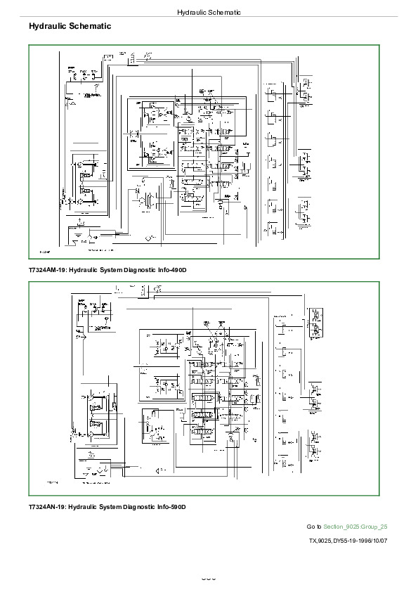
Hydraulic System
Engine
Removal And Installation
Engine Auxiliary Systems
Cold Weather Starting Aids
Cooling System
Speed Controls
Intake System
External Fuel Supply Systems
Dampener Drive (Flex Coupling)
Elements
Electrical System
Batteries, Support, And Cables
Alternator, Regulator And Charging System Wiring
Wiring Harness And Switches
Motors And Actuators
Frame Or Supporting Structure
Frame Installation
Chassis Weights
Operator’s Station
Removal And Installation
Operator Enclosure
Seat And Seat Belt
Heating And Air Conditioning
Sheet Metal And Styling
Hood Or Engine Enclosure
Excavator
Buckets
Frames
Hydraulic Systems
Swing Or Pivoting System
Mechanical Drive Elements
Hydraulic System
Dealer Fabricated Tools
TABLE OF CONTENTS
Section I: General Information…14
Group I: Safety…14
Follow Safe Procedures…18
Prepare for Emergencies…19
Prevent Acid Burns…20
Handle Chemical Products Safely…22
Handle Fluids Safely-Avoid Fires…23
Avoid High-Pressure Fluids…24
Warn Others of Service Work…25
Support Machine Properly…26
Operate Only from Operator's Seat…27
Park Machine Safely…28
Stay Clear of Moving Parts…29
Avoid Power Lines…30
Use Handholds and Steps…31
Keep Riders Off Machine…32
Move and Operate Machine Safely…33
Wear Protective Clothing…34
Protect Against Flying Debris…35
Protect Against Noise…36
Illuminate Work Area Safely…37
Service Machines Safely…38
Remove Paint Before Welding or Heating…39
Avoid Heating Near Pressurized Fluid Lines…40
Beware of Exhaust Fumes…41
Use Proper Lifting Equipment…42
Service Cooling System Safely…43
Dispose of Waste Properly…44
Work in a Clean Area…45
Use Tools Properly…46
Replace Safety Signs…47
Live With Safety…48
Group II: General Specifications…666
490D Specifications…666
490D Working Ranges…53
490D Drain And Refill Capacities…55
490D…56
490D Bucket Selection Chart-2.5 M (98 In.) Arm…58
490D Bucket Selection Chart-3.0 M (118 In.) Arm…59
490D Bucket Specifications…666
490D with 2.5 m (8 ft 2 in.) Arm Lift Capacity-Kg (Lb)…61
490D with 3.0 m (9 ft 10 in.) Arm Lift Capacity-Kg (Lb)…62
590D Specifications…666
590D Working Ranges…66
590D Operating Specifications…666
590D Drain And Refill Capacities…68
590D Engine and Hydraulic Specifications…666
590D Bucket Selection Chart-2.6 M (8 Ft 6 In.) Arm…71
590D Bucket Selection Chart-3.1 M (10 Ft. 2 In.) Arm…72
590D Bucket Specifications…666
590D Lift Capacity-Kg (Lb)…74
590D Lift Capacity-Kg (Lb)-Continued…76
Group III: Torque Values…15
Hardware Torque Specifications…666
Check Track Shoe Torque…79
Inch Cap Screw Torque Values…80
Metric Cap Screw Torque Values…82
Additional Metric Cap Screw Torque Values…84
Service Recommendations for O-Ring Boss Fittings…86
Service Recommendations For Flat Face O-Ring Seal Fittings…88
Service Recommendations For Flared Connections-Straight or Tapered Threads…90
SAE Four Bolt Flange Fitting Service Recommendations…92
Group IV: Fuels And Lubricants…15
Fuel Specifications…666
Fuel Storage…96
Engine Oil…97
Hydraulic Oil…98
Swing Gearbox, Propel Gearbox And Pump Gearbox Oils…99
Track Rollers And Idlers Oil…100
Swing Gear Grease…102
Grease…102
Lubricant Storage…103
Alternative Lubricants…104
Section 01: Tracks…105
Group 0130: Track System…105
Service Equipment And Tools…664
Other Material…665
Specifications…666
Measure Lower Track Roller Wear…110
Remove And Install Lower Track Roller…111
Disassemble And Assemble Lower Track Roller…113
Inspect Metal Face Seals…221
Measure Upper Track Roller Wear…122
Remove And Install Upper Track Roller…123
Assemble Upper Track Roller…126
Measure Track Shoe Grouser Wear…128
Remove And Install Track Shoe…129
Measure Track Link Wear…130
Measure Track Bushing Wear…131
Measure Track Pitch…132
Remove Track Chain…133
Install Track Chain…135
Disassemble And Assemble Track Chain…137
Adjust Track Sag…138
Measure Sprocket Wear…140
Remove And Install Sprocket…141
Measure Front Idler Wear…143
Remove And Install Front Idler…144
Disassemble Front Idler…145
Assemble Front Idler…148
Remove And Install Track Adjuster…151
Disassemble Track Adjuster…154
Assemble Track Adjuster…161
Section 02: Axles And Suspension Systems (Propel)…166
Group 0250: Axle Shaft, Bearings, And Reduction Gears…166
Service Equipment And Tools…664
Other Material…665
Specifications…666
Towing The Excavator-490D…171
Towing The Excavator-590D…174
Remove And Install Propel Gearbox-490D…178
Disassemble Propel Gearbox-490D…181
Assemble Propel Gearbox-490D…191
Remove And Install Propel Gearbox-590D…201
Disassemble Propel Gearbox-590D…205
Assemble Propel Gearbox-590D…214
Inspect Metal Face Seals…221
Group 0260: Hydraulic System…166
Essential Tools…495
Service Equipment And Tools…664
Other Material…665
Specifications…666
Remove And Install Propel Motor-490D…228
Disassemble Propel Motor-490D…233
Inspect Propel Motor-490D…243
Assemble Propel Motor-490D…247
Remove And Install Propel Motor-590D…257
Disassemble Propel Motor-590D…260
Assemble Propel Motor-590D…269
Remove And Install Propel Hydraulic Lines…276
Remove And Install Rotary Manifold…278
Disassemble And Assemble Rotary Manifold…281
Rotary Manifold Air Test…283
Section 04: Engine…284
Group 0400: Removal And Installation…284
4276 John Deere Engine Repair-Use CTM-4…286
Essential Tools…495
Other Material…665
Specifications…666
Remove And Install Engine-490D…292
Remove And Install Engine-590D…297
Remove And Install Oil Pan…301
Remove Fuel Injection Pump…302
Install Fuel Injection Pump…304
Remove And Install Fuel Injection Nozzles…306
Bleed Fuel System…309
Remove And Install Water Pump…311
Remove And Install Turbocharger-590D…313
Section 05: Engine Auxiliary Systems…315
Group 0505: Cold Weather Starting Aids…315
Other Material…665
Specifications…666
Remove And Install Starting Aid Solenoid And Nozzle…319
Remove And Install Engine Coolant Heater…321
Group 0510: Cooling System…315
Service Equipment And Tools…664
Specifications…666
Remove And Install Fan…326
Remove And Install Fan Belt…327
Fan Belt Tension Adjustment…328
Remove And Install Radiator…329
Group 0515: Speed Controls…315
Other Material…665
Specifications…666
Remove And Install Speed Control Assembly…333
Engine Speed Adjustment…334
Speed Control Linkage Adjustment…337
Speed Control Lever Tension Adjustment…340
Group 0520: Intake System…315
Service Equipment And Tools…664
Specifications…666
Remove And Install Air Cleaner-490D…344
Remove And Install Air Cleaner-590D…345
Air Intake System Leakage Test…346
Group 0560: External Fuel Supply Systems…315
Specifications…666
Remove And Install Fuel Tank…350
Remove And Install Fuel Filter…352
Section 07: Dampener Drive (Flex Coupling)…354
Group 0752: Elements…354
Other Material…665
Specifications…666
Disassemble And Assemble Flex Coupling-490D…358
Disassemble And Assemble Flex Coupling-590D…361
Section 16: Electrical System…363
Group 1671: Batteries, Support, And Cables…363
Specifications…666
Handle Batteries Safely…366
Test Batteries Using Coolant And Battery Tester…367
Test Batteries Using High Rate Discharge Test…368
Prevent Fire Hazards When Using Booster Batteries…369
Charge Battery…370
Remove And Install Batteries…371
Group 1672: Alternator, Regulator And Charging System Wiring…363
John Deere Engine Accessories-Alternator Repair-Use CTM-11…373
Service Equipment And Tools…664
Specifications…666
Remove And Install…376
Group 1674: Wiring Harness And Switches…363
Remove And Install Dome Light Switch…379
Remove And Install Control Panel Switches…380
Remove And Install Relay Starter Solenoid…381
Remove And Install Engine Hourmeter Switch…382
Remove And Install Engine Overheat Alarm Switch…383
Remove And Install Air Cleaner Restriction Indicator…384
Remove And Install Battery Relay…386
Remove And Install Battery Relay…386
Remove And Install Buzzer Stop Switch…387
Remove And Install Travel Alarm-590D…388
Changing Travel Alarm Volume…389
Group 1677: Motors And Actuators…363
John Deere Starting Motor Repair Use CTM-11…391
Service Equipment And Tools…664
Specifications…666
Remove And Install Starting Motor…394
Section 17: Frame Or Supporting Structure…395
Group 1740: Frame Installation…395
Welding Repair Of Major Structure…397
Group 1749: Chassis Weights…395
Essential Tools…495
Specifications…666
Remove And Install Counterweight…401
Section 18: Operator’s Station…402
Group 1800: Removal And Installation…402
Other Material…665
Specifications…666
Remove And Install Cab And Cab Floor…406
Remove And Install Cab (Without Floor)…413
Group 1810: Operator Enclosure…402
Service Equipment And Tools…664
Other Material…665
Remove And Install Windowpane And Two Piece Molding…418
Remove And Install Windowpane And One Piece Molding…420
Remove And Install Sliding Windows…421
Windowpane Dimensions…423
Remove And Install Cab Door…424
Remove And Install Door Latch…425
Remove And Install Inside Assist Handle…426
Remove, Disassemble, Assemble, And Install Windshield Wiper…427
Remove And Install Defroster Fan…428
Disassemble And Assemble Defroster Fan…429
Group 1821: Seat And Seat Belt…402
Disassemble And Assemble Seat…431
Group 1830: Heating And Air Conditioning…402
Disassemble And Assemble Blower Motor…433
Remove And Install 13,500 BTU Heater…434
Remove And Install 13,500 BTU Cab Heater Lines And Controls…436
Remove And Install 19,000 BTU Heater…438
Remove And Install 19,000 BTU Cab Heater Lines And Controls…439
Remove And Install 40,000 BTU Heater…441
Remove And Install 40,000 BTU Cab Heater Lines And Controls…442
Section 19: Sheet Metal And Styling…444
Group 1910: Hood Or Engine Enclosure…444
Specifications…666
Remove And Install Hood…447
Adjust Hood Latch Catch…448
Remove And Install Service Doors…449
Remove And Install Top Cover…450
Section 33: Excavator…451
Group 3302: Buckets…451
Service Equipment And Tools…664
Specifications…666
Remove And Install Bucket And Linkage…458
Remove And Install Bushings…492
Inspect Bucket Linkage Pins And Bushings…465
Adjust Bucket Pivot End Play…466
Disassemble And Assemble Bucket…467
Remove And Install Tooth Tip…468
Remove Tooth Shank…469
Install Tooth Shank…470
Group 3340: Frames…451
Service Equipment And Tools…664
Other Material…665
Specifications…666
Remove Arm…477
Install Arm…481
Remove Boom…484
Install Boom…488
Inspect Arm And Boom Pins And Bushings…491
Remove And Install Bushings…492
Group 3360: Hydraulic Systems…451
Essential Tools…495
Service Equipment And Tools…664
Other Material…665
Specifications…666
Hydraulic Cylinder Bleed Procedure…583
Release Pressure In Hydraulic System…502
Remove And Install Hydraulic Pump…504
Hydraulic Pump Start-Up Procedure…506
Disassemble Hydraulic Pump…507
Assemble Hydraulic Pump…511
Remove And Install Hydraulic Pump Regulator…514
Disassemble Pump Regulator…515
Assemble Pump Regulator…520
Remove And Install Pilot Pump…524
Disassemble And Assemble Pilot Pump…525
Remove And Install Solenoid Valve And Pilot Pressure Regulating Valve…527
Disassemble And Assemble Solenoid Valve And Pilot Pressure Regulating Valve…530
Remove And Install Engine Speed Mode Selection Cylinders…533
Disassemble And Assemble Engine Speed Mode Selection Cylinders…534
Remove And Install Hydraulic Control Valve…535
Disassemble Hydraulic Control Valve…542
Assemble Hydraulic Control Valve…553
Remove And Install Reservoir…564
Remove And Install Return Filter And Suction Filter…569
Remove And Install Oil Cooler Restriction Valve…572
Disassemble And Assemble Oil Cooler Restriction Valve…573
Remove And Install Oil Cooler Bypass Valve…574
Disassemble And Assemble Oil Cooler Bypass Valve…575
Remove And Install Oil Cooler…576
Remove And Install Bucket Cylinder…577
Remove And Install Arm Cylinder…579
Remove And Install Boom Cylinder…581
Hydraulic Cylinder Bleed Procedure…583
Disassemble Bucket, Arm And Boom Cylinders…584
Inspection Of Cylinder Rod…589
Assemble Bucket, Arm, And Boom Cylinders…590
Inspection Of Cylinder Pins And Bushings…596
Remove And Install Auxiliary Shut-Off Valve…597
Disassemble And Assemble Auxiliary Shut-Off Valve…599
Remove And Install Propel Function Ler Valve…601
Disassemble Propel Function Pilot Controller Valve…603
Assemble Propel Function Pilot Controller Valve…606
Remove And Install Dig Function Pilot Controller Valve…609
Disassemble Dig Function Pilot Controller Valve…612
Assemble Dig Function Pilot Controller Valve…615
Remove And Install Pilot Shut-Off Valve…618
Pilot Shut-Off Valve Linkage Adjustment…620
Disassemble And Assemble Pilot Shut-Off Valve…621
Disassemble And Assemble Pilot Filter…623
Inspect Pilot Filter Relief Valve…624
Remove And Install Flow Control Valve…625
Disassemble And Assemble Flow Control Valve…627
Remove And Install Check Valve Block…629
Disassemble And Assemble Check Valve Block…631
Section 43: Swing Or Pivoting System…632
Group 4350: Mechanical Drive Elements…632
Service Equipment And Tools…664
Other Material…665
Specifications…666
Remove And Install Swing Gearbox…637
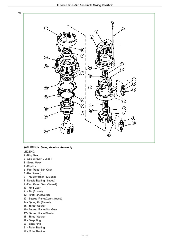
Disassemble And Assemble Swing Gearbox…639
Remove And Install Swing Bearing…648
Disassemble And Assemble Swing Bearing…657
Install Swing Bearing Seals…662
Group 4360: Hydraulic System…632
Service Equipment And Tools…664
Other Material…665
Specifications…666
Remove And Install Swing Motor…667
Disassemble Swing Motor…669
Assemble Swing Motor…676
Disassemble And Assemble Crossover Relief Valves…682
Remove And Install Make-Up Valves…686
Disassemble And Assemble Swing Brake Release Valve…687
Section 99: Dealer Fabricated Tools…691
Group 9900: Dealer Fabricated Tools…691
DF1036 Propel Gearbox Nut Wrench-490D…693
DFT1070 Propel Gearbox Nut Wrench-590D…694
DF1038 Torque Adapter…695
Rotary Manifold Lifting Tool…696
ST4920 Track Recoil Spring Disassembly And Assembly Tool…697
DFT1087 Track Recoil Spring Disassembly And Assembly Guard Tool…701
John Deere 490D and 590D Excavator Repair Technical Manual (TM1390)