Posted on

John Deere 35G Compact Excavator Repair Technical Manual (TM12894)


INSTANT DOWNLOAD


Complete service repair manual for John Deere 35G, with all the shop information to maintain, repair, and rebuild like professional mechanics.

John Deere 35G Compact Excavator workshop service repair manual includes:
* Numbered table of contents easy to use so that you can find the information you need fast.
* Detailed sub-steps expand on repair procedure information
* Numbered instructions guide you through every repair procedure step by step.
* Notes, cautions and warnings throughout each chapter pinpoint critical information.
* Bold figure number help you quickly match illustrations with instructions.
* Detailed illustrations, drawings and photos guide you through every procedure.
* Enlarged inset helps you identify and examine parts in detail.

TM12894 English – John Deere 35G Compact Excavator Technical Manual – Repair.pdf
tm12895 French – Excavatrice 35G.pdf
tm12896 Spanish – Excavadora 35G

Total Pages: 554 pages
File Format: PDF (bookmarked, ToC, Searchable, Printable)
Language: English French Spanish

MAIN SECTIONS
Foreword
Technical Information Feedback Form
General Information
Safety
Torque Values
Tracks
Track System
Axles and Suspension Systems (Travel)
Axle Shaft, Bearings, and Reduction Gears
Hydraulic System
Engine
Removal and Installation
Engine Auxiliary System
Cooling Systems
External Fuel Supply Systems
Dampener Drive (Flex Coupling)
Elements
Frame or Supporting Structure
Frame Installation
Chassis Weights
Operator`s Station
Removal and Installation
Operator Enclosure
Seat and Seat Belt
Heating and Air Conditioning
Blade (Backfill)
Blades
Hydraulic System
Excavator
Buckets
Frames
Hydraulic System
Swing or Pivoting System
Mechanical Drive Elements
Hydraulic System
Dealer Fabricated Tools

TABLE OF CONTENTS
Section 00: General Information..10
Group 0001: Safety..10
Recognize Safety Information..13
Follow Safety Instructions..14
Operate Only If Qualified..15
Wear Protective Equipment..16
Avoid Unauthorized Machine Modifications..17
Control Pattern Selector—If Equipped..18
Add Cab Guarding for Special Uses..19
Inspect Machine..20
Stay Clear of Moving Parts..21
Avoid High-Pressure Fluids..22
Avoid High-Pressure Oils..23
Work In Ventilated Area..24
Prevent Fires..25
Prevent Battery Explosions..26
Handle Chemical Products Safely..27
Decommissioning — Proper Recycling and Disposal of Fluids and Components..28
Prepare for Emergencies..29
Clean Debris from Machine..30
Use Steps and Handholds Correctly..31
Start Only From Operator's Seat..32
Use and Maintain Seat Belt..33
Prevent Unintended Machine Movement..34
Avoid Work Site Hazards..35
Keep Riders Off Machine..37
Avoid Backover Accidents..38
Inspect and Maintain ROPS..39
Avoid Machine Tip Over..40
Use Special Care When Lifting Objects..42
Add and Operate Attachments Safely..43
Park and Prepare for Service Safely..44
Service Cooling System Safely..45
Remove Paint Before Welding or Heating..46
Make Welding Repairs Safely..47
Drive Metal Pins Safely..48
Group 0003: Torque Values..11
Metric Bolt and Cap Screw Torque Values..51
Additional Metric Cap Screw Torque Values..53
Unified Inch Bolt and Cap Screw Torque Values..55
Service Recommendations for 37° Flare and 30° Cone Seat Connectors..57
Service Recommendations for O-Ring Boss Fittings..59
Service Recommendations for Flared Connections—Straight or Tapered Threads..61
Service Recommendations for Flat Face O-Ring Seal Fittings..63
O-Ring Boss Fittings in Aluminum Housing Service Recommendations—Excavators..65
O-Ring Face Seal Fittings With SAE Inch Hex Nut and Stud End for High-Pressure Service Recommendations..68
O-Ring Face Seal Fittings With Metric Hex Nut and Stud End for Standard Pressure Service Recommendations..70
O-Ring Face Seal Fittings With Metric Hex Nut and Stud End for High-Pressure Service Recommendations..73
Service Recommendations for Metric Series Four Bolt Flange Fitting..76
Service Recommendations For Inch Series Four Bolt Flange Fittings..78
Inch Series Four Bolt Flange Fitting for High-Pressure Service Recommendations..80
Service Recommendations For Non-Restricted Banjo (Adjustable) Fittings..82
Service Recommendations For O-Ring Boss Fittings With Shoulder..85
Metric 24° O-Ring Seal DIN 20078 Service Recommendations..88
Section 01: Tracks..92
Group 0130: Track System..92
Track Roller Remove and Install..97
Track Roller Disassemble and Assemble..101
Track Roller Pressure Test..104
Track Carrier Roller Remove and Install..107
Inspect Metal Face Seals..111
Rubber Track Remove and Install..113
Track Shoe Remove and Install..118
Track Chain Remove and Install..120
Track Chain Disassemble and Assemble..125
Track Chain Repair to Replace Broken Part..128
Sprocket Remove and Install..134
Front Idler Remove and Install..136
Front Idler Disassemble and Assemble..138
Track Adjuster and Recoil Spring Remove and Install..143
Track Adjuster and Recoil Spring Disassemble and Assemble..144
Section 02: Axles and Suspension Systems (Travel)..153
Group 0250: Axle Shaft, Bearings, and Reduction Gears..153
Travel Gear Case Remove and Install..158
Travel Gear Case Disassemble and Assemble..162
Group 0260: Hydraulic System..153
Travel Motor and Park Brake Remove and Install..173
Travel Motor and Park Brake Disassemble and Assemble..174
Park Brake Valve Disassemble and Assemble..184
Travel Motor and Park Brake Start-Up Procedure..187
Section 04: Engine..189
Group 0400: Removal and Installation..189
Engine Remove and Install..201
Section 05: Engine Auxiliary System..212
Group 0510: Cooling Systems..212
Radiator Remove and Install..217
Hydraulic Oil Cooler Remove and Install..221
Fan, Fan Guard, and Fan Shroud Remove and Install..228
Coolant Recovery Tank Remove and Install..230
Group 0560: External Fuel Supply Systems..212
Fuel Tank Remove and Install..236
Fuel Pump Remove and Install..240
Primary Fuel Filter and Water Separator Housing Remove and Install..241
Final Fuel Filter Housing Remove and Install..243
Section 07: Dampener Drive (Flex Coupling)..245
Group 0752: Elements..245
Damper Drive (Flex Coupling) Remove and Install..248
Section 17: Frame or Supporting Structure..250
Group 1740: Frame Installation..250
Welding on Machine..253
Group 1749: Chassis Weights..250
Counterweight Remove and Install..260
Section 18: Operator's Station..265
Group 1800: Removal and Installation..265
Cab Remove and Install..269
Canopy Remove and Install..272
Platform Remove and Install..276
Group 1810: Operator Enclosure..265
Windshield Remove and Install..287
Windshield Disassemble and Assemble..289
Windowpanes Remove and Install..294
Windowpanes Dimensions..295
Group 1821: Seat and Seat Belt..265
Seat Remove and Install..303
Seat Belt Remove and Install..304
Left and Right Console Covers Remove and Install..306
Group 1830: Heating and Air Conditioning..265
Refrigerant Cautions and Proper Handling..310
Flush and Purge Air Conditioning System..311
R134a Refrigerant Oil Information..315
R134a Refrigerant Recovery, Recycling, and Charging Station Installation Procedure..317
R134a Compressor Oil Charge Check..319
R134a Compressor Oil Removal..321
Recover R134a Refrigerant..322
Evacuate R134a System..323
Charge R134a System..325
Air Conditioner Compressor Remove and Install..326
Condenser Remove and Install..328
Heater and Air Conditioner Remove and Install..332
Receiver-Dryer Remove and Install..336
Section 32: Blade (Backfill)..338
Group 3201: Blades..338
Blade Remove and Install..342
Blade Disassemble and Assemble..345
Angle Blade Remove and Install—If Equipped..346
Angle Blade Frame Remove and Install—If Equipped..348
Angle Blade and Frame Disassemble and Assemble—If Equipped..352
Group 3260: Hydraulic System..338
Blade Cylinder Remove and Install..357
Blade Pilot Valve Remove and Install..360
Blade Pilot Valve Disassemble and Assemble..363
Angle Blade Cylinder Remove and Install—If Equipped..366
Angle Blade Solenoid Valve Remove and Install—If Equipped..369
Angle Blade Solenoid Valve Disassemble and Assemble—If Equipped..371
Section 33: Excavator..375
Group 3302: Buckets..375
Bucket Remove and Install..378
Bucket Pin-Up Data..379
Group 3340: Frames..375
Bucket Links Remove and Install..384
Bucket Quick Coupler Remove and Install..387
Arm Remove and Install..390
Boom Remove and Install..394
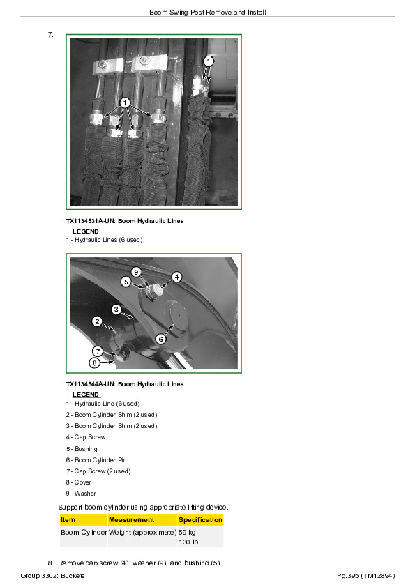
Boom Swing Post Remove and Install..399
Inspect Pins and Bushings—Front Attachment and Blade..403
Cylinder Specifications..408
Bushing and Seal Remove and Install..409
Group 3360: Hydraulic System..375
Apply Vacuum to Hydraulic Oil Tank..412
General Hydraulic Oil Cleanup Procedure..413
Hydraulic Component Failure Cleanup Procedure..416
Hydraulic Pump 1, 2, and 3 Remove and Install..419
Hydraulic Pump 1, 2, and 3 Disassemble and Assemble..422
Pilot Pump Remove and Install..439
Pilot Pump Disassemble and Assemble..441
Hydraulic Pump Start-Up Procedure..443
Pilot Pressure Regulator and Solenoid Valve Manifold Remove and Install—Pilot Shutoff and Travel Speed Solenoids..444
Pilot Pressure Regulator and Solenoid Valve Manifold Disassemble and Assemble—Pilot Shutoff and Travel Speed Valves..446
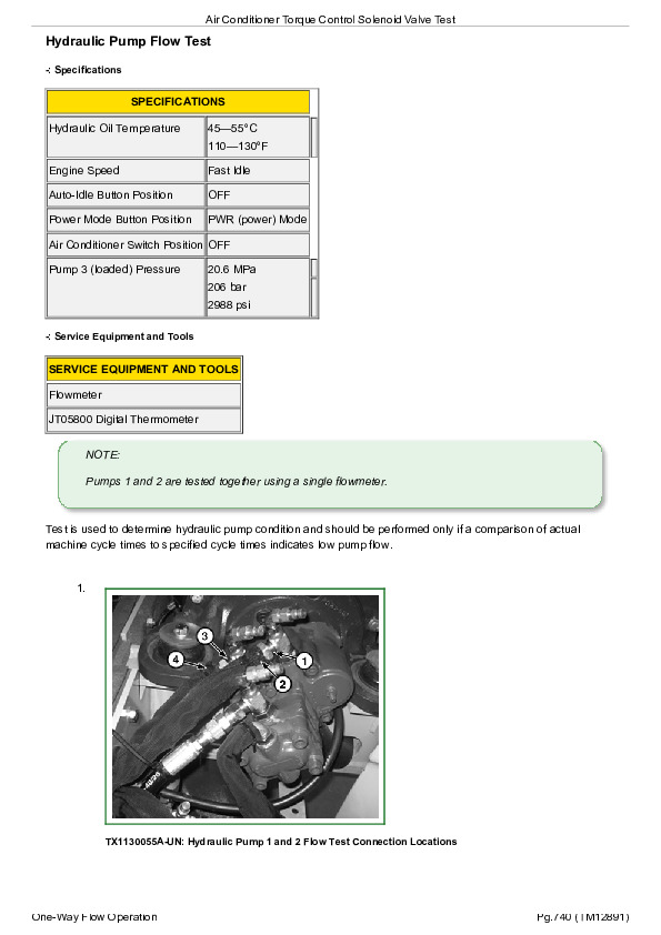
Air Conditioner Torque Control Solenoid Valve Remove and Install..450
Air Conditioner Torque Control Solenoid Valve Disassemble and Assemble..452
Pilot Valve (Left and Right) Remove and Install..454
Pilot Valve (Left and Right) Disassemble and Assemble..457
Travel Pilot Valve Remove and Install..466
Travel Pilot Valve Disassemble and Assemble..468
Boom Swing Pilot Valve Remove and Install..473
Boom Swing Pilot Valve Disassemble and Assemble..475
Control Valve Remove and Install..478
Control Valve Disassemble and Assemble..481
Control Lever Pattern Selector Remove and Install..515
Control Lever Pattern Selector Disassemble and Assemble..519
Hydraulic Oil Tank Remove and Install..521
Hydraulic Oil Tank Disassemble and Assemble..526
Hydraulic Oil Cooler Bypass Valve Remove and Install (S.N. —272504)..530
Hydraulic Oil Cooler Bypass Valve Remove and Install (S.N. 272505— )..533
Boom Cylinder Remove and Install..536
Boom Cylinder Disassemble and Assemble..540
Arm Cylinder Remove and Install..544
Arm Cylinder Disassemble and Assemble..549
Bucket Cylinder Remove and Install..553
Bucket Cylinder Disassemble and Assemble..557
Boom Swing Cylinder Remove and Install..561
Boom Swing Cylinder Disassemble and Assemble..565
Blade Lift Cylinder Disassemble and Assemble..569
Angle Blade Cylinder Disassemble and Assemble—If Equipped..573
Hydraulic Cylinder Bleed Procedure..577
Section 43: Swing or Pivoting System..578
Group 4350: Mechanical Drive Elements..578
Swing Gear Case Remove and Install..582
Swing Gear Case Disassemble and Assemble..585
Upperstructure Remove and Install..590
Swing Bearing Remove and Install..594
Group 4360: Hydraulic System..578
Center Joint Remove and Install..603
Center Joint Disassemble and Assemble..608
Center Joint Air Test..612
Swing Motor and Park Brake Remove and Install..613
Swing Motor and Park Brake Disassemble and Assemble..616
Swing Motor and Park Brake Start-Up Procedure..623
Crossover Relief Valve and Make-Up Check Valve Remove and Install..624
Swing Park Brake Check Valve and Orifice Remove and Install..627
Section 99: Dealer Fabricated Tools..631
Group 9900: Dealer Fabricated Tools..631
ST4920 Track Recoil Spring Disassembly and Assembly Tool..637
DFT1087 Track Recoil Spring Disassembly and Assembly Guard Tool..642
DFT1110 Spacer..643

John Deere 35G Compact Excavator Repair Technical Manual (TM12894)


INSTANT DOWNLOAD


Posted on

John Deere 35G Excavator Operator’s Manual (OMT333111)


INSTANT DOWNLOAD


Complete Operator’s manual for John Deere 35G Excavator.

OMT333111 English – 35G Excavator Operator’s Manual.pdf

PRODUCT DETAILS:
Total Pages: 465 pages
File Format: PDF (Internal Links, Bookmarked, Table of Contents, Searchable, Printable, high quality)
Language: English

Also Available Now:
omt333112 Spanish – Excavadora 35G.pdf
omt333113 French – Excavatrice 35G.pdf

TABLE OF CONTENTS
Section 1-1: Safety—Safety and Operator Conveniences….21
Safety and Operator Convenience Features….22
Section 1-2: Safety—General Precautions….23
Recognize Safety Information….24
Follow Safety Instructions….25
Operate Only If Qualified….26
Wear Protective Equipment….27
Avoid Unauthorized Machine Modifications….28
Control Pattern Selector—If Equipped….29
Add Cab Guarding for Special Uses….30
Inspect Machine….31
Stay Clear of Moving Parts….32
Avoid High-Pressure Fluids….33
Avoid High-Pressure Oils….34
Work In Ventilated Area….35
Avoid Static Electricity Risk When Refueling….36
Prevent Fires….38
Prevent Battery Explosions….39
Handle Chemical Products Safely….40
Decommissioning — Proper Recycling and Disposal of Fluids and Components….41
Prepare for Emergencies….42
Clean Debris from Machine….43
Section 1-3: Safety—Operating Precautions….44
Use Steps and Handholds Correctly….45
Start Only From Operator's Seat….46
Use and Maintain Seat Belt….47
Prevent Unintended Machine Movement….48
Avoid Work Site Hazards….49
Keep Riders Off Machine….51
Avoid Backover Accidents….52
Avoid Machine Tip Over….53
Inspect and Maintain ROPS….55
Prevent Acid Burns….56
Travel Safely….58
Use Special Care When Lifting Objects….59
Add and Operate Attachments Safely….60
Section 1-4: Safety—Maintenance Precautions….61
Park and Prepare for Service Safely….62
Service Cooling System Safely….63
Remove Paint Before Welding or Heating….64
Make Welding Repairs Safely….65
Drive Metal Pins Safely….66
Section 1-5: Safety—Safety Signs….68
Safety Signs….68
Section 2-1: Operation—Operator’s Station….76
Right Console—Cab….77
Right Console—Canopy….78
Key Switch….79
Pedals and Levers….80
Engine Speed Dial….82
Horn….83
Pilot Shutoff Lever….84
Travel Alarm Cancel Switch….85
Cab Heater and Air Conditioner—If Equipped….86
Operating AM/FM Radio—If Equipped….93
Cab Dome Light—If Equipped….97
12 Volt Auxiliary Power Outlet….98
Door Release Lever—If Equipped….99
Front (Alternative Exit) Window—If Equipped….100
Removing Lower Front Window—If Equipped….102
Fire Extinguisher Mounting Location….103
Alternative Exit Tool—If Equipped….104
Opening Right Side Window—If Equipped….105
Adjusting Operator Seat….106
Operator’s Manual Compartment….107
Section 2-2: Operation—Monitor Operation….108
Monitor….109
Monitor Functions….111
Monitor Start-Up….113
Menu….116
Menu—Alarm List….119
Menu—Auto-Shutdown….123
Menu—Clock….125
Menu—Trip….128
Menu—Brightness Adjustment….132
Section 2-3: Operation—Operating the Machine….135
Operating in High Altitude….136
Before Starting Work….137
Inspect Machine Daily Before Starting….138
Starting the Engine….412
Starting the Engine in Cold Weather….141
Checking Instruments After Starting….144
Cold Weather Warm-Up….145
Travel Pedals and Levers….146
Control Lever Pattern Operation….148
Control Lever Pattern Conversion….150
Multi-Function Control Lever….151
Boom-Swing Pedal….153
Positioning Auxiliary Line Selector Valve….155
Operating Backfill Blade….157
Operating Angle Blade—If Equipped….159
Operating Tips—Backfill Blade….160
Operating in Water and Mud….161
Selecting Correct Track….162
Driving Up a Steep or Slippery Slope….163
Lower Boom With Engine Stopped….164
Parking the Machine….168
Loading and Unloading for Transport….169
Towing Machine a Short Distance….171
Lifting….172
Lifting Machine….174
Section 3-1: Maintenance—Machine….176
Required Emission-Related Information….177
Diesel Fuel….178
Diesel Fuel Specifications….179
Lubricity of Diesel Fuel….180
Biodiesel Fuel….181
Supplemental Diesel Fuel Additives….183
Fuel Filters….184
Minimizing the Effect of Cold Weather on Diesel Engines….185
Testing Diesel Fuel….187
Handling and Storing Diesel Fuel….188
Alternative and Synthetic Lubricants….189
Lubricant Storage….190
Mixing of Lubricants….191
John Deere Break-In Plus™ Engine Oil — Interim Tier 4, Final Tier 4, Stage IIIB, Stage IV, and Stage V….192
Diesel Engine Oil — Interim Tier 4, Final Tier 4, Stage IIIB, Stage IV, and Stage V….193
Engine Oil and Filter Service Intervals — Interim Tier 4, Final Tier 4, Stage IIIB, Stage IV, and Stage V Engines….195
Oil Filters….197
Hydraulic Oil….198
Travel Gear Case Oil….200
Grease….201
Diesel Engine Coolant (engine without wet sleeve cylinder liners)….203
Water Quality for Mixing with Coolant Concentrate….205
Supplemental Coolant Additives….206
Operating in Warm Temperature Climates….207
Testing Coolant Freeze Point….208
Disposing of Coolant….210
Section 3-2: Maintenance—Periodic Maintenance….211
Service Machine at Specified Intervals….212
Check the Hour Meter Regularly….213
Prepare Machine for Maintenance….214
Engine Access Door….216
Open Maintenance Access Doors….217
Tilting Operator’s Station….219
Fuel Tank….227
Check Windshield Washer Fluid Level—If Equipped….228
Hydraulic Breaker and Crusher Attachments….229
Fluid Analysis Program Test Kits and 3-Way Coolant Test Kit….230
Service Intervals….231
Required Parts….233
Section 3-3: Maintenance—As Required….234
Clean Radiator Core and Oil Cooler….235
Check and Clean Air Cleaner Dust Unloader Valve….236
Replace Engine Air Filter….237
Check and Adjust Air Conditioner Belt—If Equipped….239
Check Track Sag—Rubber Track….241
Check Track Sag—Steel Track—If Equipped….243
Adjust Track Sag….245
Section 3-4: Maintenance—Every 10 Hours or Daily….247
Check Engine Oil Level….248
Check Hydraulic Tank Oil Level….250
Drain Water and Sediment from Fuel Tank Sump….252
Drain Water and Sediment from Primary Fuel Filter and Water Separator….253
Check Engine Coolant Level….254
Check Bucket Teeth….256
Check Seat Belt….257
Lubricate Bucket and Link Pins….266
Lubricate Front End Pin Joints….285
Section 3-5: Maintenance—Initial Service – 50 Hours….262
Check and Adjust Fan Belt Tension….270
Section 3-6: Maintenance—Every 100 Hours….265
Lubricate Bucket and Link Pins….266
Lubricate Front End Pin Joints….285
Check and Adjust Fan Belt Tension….270
Section 3-7: Maintenance—Initial Service – 250 Hours….272
Replace Hydraulic Tank Oil Filter….294
Section 3-8: Maintenance—Every 250 Hours….276
Lubricate Swing Bearing….277
Check Travel Gear Case Oil Level….278
Drain Water and Sediment From Hydraulic Tank….279
Take Engine Oil Sample….281
Section 3-9: Maintenance—Every 500 Hours….282
Drain and Refill Engine Oil and Replace Filter….283
Lubricate Front End Pin Joints….285
Lubricate Swing Bearing Gear….288
Lubricate Control Lever Universal Joint….289
Lubricate Blade Pins….290
Replace Primary Fuel Filter and Water Separator….291
Replace Final Fuel Filter….293
Replace Hydraulic Tank Oil Filter….294
Take Fluid Samples….297
Section 3-10: Maintenance—Every 1000 Hours….298
Replace Pilot System Oil Filter….299
Drain and Refill Travel Gear Case Oil….302
Check and Adjust Engine Valve Lash….304
Check Starter and Alternator….305
Section 3-11: Maintenance—Every 2000 Hours….306
Drain and Refill Hydraulic Tank Oil and Clean Suction Screen….307
Drain Cooling System….311
Cooling System Fill and Deaeration Procedure….313
Section 4-1: Miscellaneous—Machine….315
Bleed Fuel System….316
Do Not Service or Adjust Injection Nozzles or High Pressure Fuel Pump….317
Do Not Service Control Valves, Cylinders, Pumps, or Motors….318
Precautions for Alternator and Regulator….319
Using Booster Batteries—12-Volt System….320
Handling, Checking, and Servicing Batteries Carefully….321
Using Battery Charger….323
Replacing Battery….325
Welding on Machine….326
Bleed Hydraulic System….420
Clean Machine Regularly….329
Adding 12-Volt Accessories….330
Connecting and Disconnecting Auxiliary Lines….331
Replacing Fuses….334
Clean Cab Fresh Air and Cab Recirculating Air Filters—If Equipped….337
Replacing Bucket Teeth….339
Replacing Bucket Teeth—TK Series….341
Installing Bucket With Quick Coupler….342
Track Sag General Information….344
Check Track Shoe Hardware….345
Rubber Track Care….346
Removing and Installing Rubber Track….347
Converting the Track….350
Hardware Torque Specifications….351
Unified Inch Bolt and Screw Torque Values….352
Metric Bolt and Screw Torque Values….355
Section 4-2: Miscellaneous—Operational Checkout….358
Operational Checkout….358
Section 4-3: Miscellaneous—Troubleshooting….410
Troubleshooting Procedure….411
Engine….412
Electrical System….417
Hydraulic System….420
Section 4-4: Miscellaneous—Storage….423
Prepare Machine for Storage….424
Monthly Storage Procedure….426
Section 4-5: Miscellaneous—Serial Numbers….428
Record Product Identification Number (PIN)….429
Record Engine Serial Number….430
Keep Proof of Ownership….431
Keep Machines Secure….432
Section 4-6: Miscellaneous—Specifications….433
Engine Specifications….434
Drain and Refill Capacities….435
Machine Specifications….436
Working Ranges….438
Excavator Lift Capacity—KG (LB.) (Canopy, Standard Arm, Standard Counterweight, and Rubber Track with Blade)….440
Excavator Lift Capacity—KG (LB.) (Canopy, Standard Arm, Standard Counterweight, and Steel Track with Blade)….441
Excavator Lift Capacity—KG (LB.) (Canopy, Long Arm, Standard Counterweight, and Rubber Track with Blade)….442
Excavator Lift Capacity—KG (LB.) (Canopy, Long Arm, Standard Counterweight, and Steel Track with Blade)….443
Excavator Lift Capacity—KG (LB.) (Canopy, Standard Arm, Extra Counterweight, and Rubber Track with Blade)….444
Excavator Lift Capacity—KG (LB.) (Canopy, Standard Arm, Extra Counterweight, and Steel Track with Blade)….445
Excavator Lift Capacity—KG (LB.) (Canopy, Long Arm, Extra Counterweight, and Rubber Track with Blade)….446
Excavator Lift Capacity—KG (LB.) (Canopy, Long Arm, Extra Counterweight, and Steel Track with Blade)….447
Excavator Lift Capacity—KG (LB.) (Cab, Standard Arm, Standard Counterweight, and Rubber Track with Blade)….448
Excavator Lift Capacity—KG (LB.) (Cab, Standard Arm, Standard Counterweight, and Steel Track with Blade)….449
Excavator Lift Capacity—KG (LB.) (Cab, Long Arm, Standard Counterweight, and Rubber Track with Blade)….450
Excavator Lift Capacity—KG (LB.) (Cab, Long Arm, Standard Counterweight, and Steel Track with Blade)….451
Excavator Lift Capacity—KG (LB.) (Cab, Standard Arm, Extra Counterweight, and Rubber Track with Blade)….452
Excavator Lift Capacity—KG (LB.) (Cab, Standard Arm, Extra Counterweight, and Steel Track with Blade)….453
Excavator Lift Capacity—KG (LB.) (Cab, Long Arm, Extra Counterweight, and Rubber Track with Blade)….454
Excavator Lift Capacity—KG (LB.) (Cab, Long Arm, Extra Counterweight, and Steel Track with Blade)….455

John Deere 35G Excavator Operator’s Manual (OMT333111)


INSTANT DOWNLOAD


Posted on

John Deere 35G Compact Excavator Operation and Test Service Manual (TM12891)


INSTANT DOWNLOAD


Complete Diagnostics, Operation and Test manual with electrical wiring diagrams for John Deere 35G Compact Excavator, with all the shop information to maintain, diagnose, and rebuild like professional mechanics.

John Deere 35G Compact Excavator workshop Operation and Test manual includes:
* Numbered table of contents easy to use so that you can find the information you need fast.
* Detailed sub-steps expand on repair procedure information
* Numbered instructions guide you through every repair procedure step by step.
* Troubleshooting and electrical service procedures are combined with detailed wiring diagrams for ease of use.
* Notes, cautions and warnings throughout each chapter pinpoint critical information.
* Bold figure number help you quickly match illustrations with instructions.
* Detailed illustrations, drawings and photos guide you through every procedure.
* Enlarged inset helps you identify and examine parts in detail.

TM12891 English – John Deere 35G Compact Excavator Technical Manual – Operation and Test.pdf
tm12892 French – Excavatrice 35G
tm12893 Spanish – Excavadora 35G

PRODUCT DETAILS:
Total Pages: 805 pages
File Format: PDF (bookmarked, ToC, Searchable, Printable)
Language: English

MAIN SECTIONS 35G (PIN: 1FF035GX**K270001—)
Foreword
Technical Information Feedback Form
General Information
Safety
Diagnostics
Engine Control Unit (ECU) Diagnostic Trouble Codes
Monitor Controller (DSZ) Diagnostic Trouble Codes
Operational Checkout Procedure
Engine
Theory of Operation
Diagnostic Information
Adjustments
Tests
Electrical System
System Information
System Diagrams
Sub-System Diagnostics
Monitor Operation
References
Power Train
Theory of Operation
Diagnostic Information
Hydraulic System
Theory of Operation
Diagnostic Information
Tests
Heating and Air Conditioning
Theory of Operation
Diagnostic Information
Tests

TABLE OF CONTENTS
Section 9000: General Information….15
Group 01: Safety….15
Recognize Safety Information….18
Follow Safety Instructions….19
Operate Only If Qualified….20
Wear Protective Equipment….21
Avoid Unauthorized Machine Modifications….22
Control Pattern Selector—If Equipped….23
Add Cab Guarding for Special Uses….24
Inspect Machine….25
Stay Clear of Moving Parts….26
Avoid High-Pressure Fluids….27
Avoid High-Pressure Oils….28
Work In Ventilated Area….29
Prevent Fires….30
Prevent Battery Explosions….31
Handle Chemical Products Safely….32
Decommissioning — Proper Recycling and Disposal of Fluids and Components….33
Prepare for Emergencies….34
Clean Debris from Machine….35
Use Steps and Handholds Correctly….36
Start Only From Operator's Seat….37
Use and Maintain Seat Belt….38
Prevent Unintended Machine Movement….39
Avoid Work Site Hazards….40
Keep Riders Off Machine….42
Avoid Backover Accidents….43
Inspect and Maintain ROPS….44
Avoid Machine Tip Over….45
Use Special Care When Lifting Objects….47
Add and Operate Attachments Safely….48
Park and Prepare for Service Safely….49
Service Cooling System Safely….50
Remove Paint Before Welding or Heating….51
Make Welding Repairs Safely….52
Drive Metal Pins Safely….53
Section 9001: Diagnostics….54
Group 10: Engine Control Unit (ECU) Diagnostic Trouble Codes….58
Engine Control Unit (ECU) Diagnostic Trouble Codes….58
000029.08 – Spare Accelerator Sensor Error (Pulse Communication) (P1227) (0001D-08)….54
000091.02 – Accelerator Sensor Intermittent Failure (P0124) (0005B-02)….54
000091.03 – Acceleration Sensor Error (High Voltage) (P0123) (0005B-03)….54
000091.04 – Acceleration Sensor Error (Low Voltage) (P0122) (0005B-04)….54
000100.01 – Oil Pressure Descend Error (P1198) (00064-01)….54
000100.04 – Oil Pressure Switch Error (P1192) (00064-04)….54
000110.00 – Cooling Water Temperature Rise Alarm (Overheat) (P0217) (0006E-00)….54
000110.02 – Cooling Water Temperature Sensor Intermittent Failure (P0119) (0006E-02)….54
000110.03 – Cooling Water Temperature Sensor Error (High Voltage) (P0118) (0006E-03)….54
000110.04 – Cooling Water Temperature Sensor Error (Low Voltage) (P0117) (0006E-04)….54
000158.00 – Power Supply Voltage Error (High Voltage) (P0563) (0009E-00)….54
000158.01 – Power Supply Voltage Error (Low Voltage) (P0562) (0009E-01)….54
000167.01 – Charge Alarm (P1568) (000A7-01)….54
000167.04 – Charge Switch Error (P1562) (000A7-04)….54
000190.00 – Overspeed Error (P0219) (000BE-00)….54
000628.02 – ECU Internal Flash ROM Error (Checksum B) (P1605) (00274-02)….54
000628.02 – ECU Internal Flash ROM Error (Checksum C) (P1606) (00274-02)….54
000628.12 – ECU Internal Flash ROM Error (Checksum A) (P0605) (00274-0C)….54
000630.02 – ECU Internal EEPROM Error (Checksum) (P1601) (00276-02)….54
000630.12 – ECU Internal EEPROM Error (Read/Write Error) (P0601) (00276-0C)….54
000638.02 – Engine Error (P1214) (0027E-02)….54
000638.03 – Rack Actuator Error (High Current) (P1213) (0027E-03)….54
000638.04 – Rack Actuator Error (Low Current) (P1212) (0027E-04)….54
000638.07 – Rack Actuator Mechanical Failure (P1211) (0027E-07)….54
000639.12 – CAN Communication Error (U0001) (0027F-0C)….54
001078.04 – Speed Sensor Error (P0340) (00436-04)….54
001079.02 – Sensor 5 V Intermittent Failure (P1644) (00437-02)….54
001079.03 – Sensor 5 V Error (High Voltage) (P0643) (00437-03)….54
001079.04 – Sensor 5 V Error (Low Voltage) (P0642) (00437-04)….54
001136.01 – ECU Temperature Rise Alarm (P0634) (00470-00)….54
001136.02 – ECU Temperature Sensor Intermittent Failure (P1664) (00470-02)….55
001136.03 – ECU Temperature Sensor Error (High Voltage) (P0669) (00470-03)….55
001136.04 – ECU Temperature Sensor Error (Low Voltage) (P0668) (00470-04)….55
001210.03 – Rack Position Sensor Error (High Voltage) (P1203) (004BA-03)….55
001210.04 – Rack Position Sensor Error (Low Voltage) (P1202) (004BA-04)….55
001485.04 – Main Relay Error (P0686) (005CD-04)….55
522241.02 – Rack Actuator Relay Intermittent Failure (P1224) (7F801-02)….55
522241.03 – Rack Actuator Relay Error B (P1223) (7F801-03)….55
522241.04 – Rack Actuator Relay Error A (P1222) (7F801-04)….55
522242.02 – CSD Solenoid Valve Intermittent Failure (P1244) (7F802-02)….55
522242.03 – CSD Solenoid Valve Error B (P1243) (7F802-03)….55
522242.04 – CSD Solenoid Valve Error A (P1242) (7F802-04)….55
522243.02 – Start Assist Relay Intermittent Failure (P1234) (7F803-02)….55
522243.03 – Start Assist Relay Error B (P1233) (7F803-03)….55
522243.04 – Start Assist Relay Error A (P1232) (7F803-04)….55
522251.03 – EGR Valve Error B (Step Motor A-Phase) (P1403) (7F80B-03)….55
522251.04 – EGR Valve Error A (Step Motor A-Phase) (P1402) (7F80B-04)….55
522252.03 – EGR Valve Error B (Step Motor B-Phase) (P1413) (7F80C-03)….55
522252.04 – EGR Valve Error A (Step Motor B-Phase) (P1412) (7F80C-04)….55
522253.03 – EGR Valve Error B (Step Motor C-Phase) (P1423) (7F80D-03)….55
522253.04 – EGR Valve Error A (Step Motor C-Phase) (P1422) (7F80D-04)….55
522254.03 – EGR Valve Error B (Step Motor D-Phase) (P1433) (7F80E-03)….55
522254.04 – EGR Valve Error A (Step Motor D-Phase) (P1432) (7F80E-04)….55
522314.00 – Abnormal Water Temperature (P1217) (7F84A-00)….55
522323.00 – Air Cleaner Clogging Alarm (P1101) (7F853-00)….55
522329.00 – Oil/Water Separator Alarm (P1151) (7F859-00)….55
522402.04 – Spare Speed Sensor Error (P1340) (7F8A2-04)….55
522727.12 – ECU Internal Sub CPU Error A (P1610) (7F9E7-0C)….55
522727.12 – ECU Internal Sub CPU Error B (P1611) (7F9E7-0C)….55
522727.12 – ECU Internal Sub CPU Error C (P1612) (7F9E7-0C)….55
522728.12 – ECU Internal Map Format Error (P1620) (7F9E8-0C)….55
Group 30: Monitor Controller (DSZ) Diagnostic Trouble Codes….121
Monitor Controller (DSZ) Diagnostic Trouble Codes….121
E:1100 – Engine Trouble Alarm….56
W:1100 – Engine Warning….56
W:1102 – Exhaust Filter Regeneration Request….56
W:1103 – Exhaust Filter Regeneration Inhibited Alarm….56
W:1104 – Intermediate Gas Temperature Sensor Error….56
W:1105 – Exhaust Filter Differential Pressure Sensor Error….56
W:1106 – Inlet Port Gas Temperature Sensor Error….56
W:1107 – Engine Injection Pressure Sensor Error….56
W:1108 – Exhaust Filter Gas Inlet Air Pressure Sensor Error….56
W:1109 – Engine Inlet Air Piping Abnormal Temperature….56
W:1110 – Air Heat Relay Error….56
W:1111 – Exhaust Filter Manual Regeneration Inhibited Alarm….56
W:1206 – Air Filter Restriction Alarm….56
W:1207 – Coolant Temperature Sensor Error….56
W:1208 – Engine Speed Sensor Error….56
W:1209 – Atmospheric Pressure Sensor Error….56
W:1210 – Water Separator Alarm….56
W:1211 – Ambient Air Temperature Sensor Error….56
W:1303 – Combustion Temperature Sensor Error….56
W:1304 – Engine Control Dial Error (CAN Signal)….56
W:1310 – CAN Communication Error….56
W:2201 – Overheat Alarm….56
W:2202 – Engine Oil Pressure Alarm….56
W:2304 – Fuel Sensor Error….56
W:2306 – Boom Bottom Pressure Sensor Error….56
W:2307 – Engine Control Dial Error (Analog Signal)….56
W:2310 – EEPROM Error….56
Section 9005: Operational Checkout Procedure….169
Group 10: Operational Checkout Procedure….169
Operational Checkout….217
Section 9010: Engine….264
Group 05: Theory of Operation….264
Yanmar Engine….280
Engine Fuel System Component Location….267
Engine Cooling System Component Location….269
Cold Weather Starting Aid….271
Engine Speed Control System Operation….272
Group 15: Diagnostic Information….264
Yanmar Engine….280
Group 20: Adjustments….264
Engine Valve Lash (Clearance) Check and Adjustment….278
Group 25: Tests….264
Yanmar Engine….280
Section 9015: Electrical System….281
Group 05: System Information….281
Electrical Diagram Information….292
Group 10: System Diagrams….281
Explanation of Wire Markings….301
Fuse and Relay Specifications….302
System Functional Schematic, Wiring Diagrams, and Component Locations Master Legend….305
System Functional Schematic….308
Floor Harness (W1) Component Location….313
Floor Harness (W1) Wiring Diagram….315
Engine Harness (W2) Component Location….319
Engine Harness (W2) Wiring Diagram….322
Air Conditioner Harness (W3) Component Location….326
Air Conditioner Harness (W3) Wiring Diagram….329
Console Harness (W4) Component Location….330
Console Harness (W4) Wiring Diagram….331
Cab Harness (W5) Component Location….332
Cab Harness (W5) Wiring Diagram….333
Auto-Shutdown Harness (W6) Component Location….334
Auto-Shutdown Harness (W6) Wiring Diagram….335
Auxiliary Function Lever Harness (W7) Component Location….336
Auxiliary Function Lever Harness (W7) Wiring Diagram….337
Air Conditioner Compressor Harness (W8) Component Location….338
Air Conditioner Compressor Harness (W8) Wiring Diagram….339
Boom Work Light Harness (W9) Component Location….340
Boom Work Light Harness (W9) Wiring Diagram….341
Canopy Work Light Harness (W13) Component Location….342
Canopy Work Light Harness (W13) Wiring Diagram….343
Angle Blade Floor Harness (W14) Component Location….344
Angle Blade Floor Harness (W14) Wiring Diagram….345
Angle Blade Solenoid Harness (W15) Component Location….346
Angle Blade Solenoid Harness (W15) Wiring Diagram….347
Windshield Wiper Extension Harness (W16) Component Location….348
Windshield Wiper Extension Harness (W16) Wiring Diagram….349
Windshield Wiper Harness (W17) Component Location….350
Windshield Wiper Harness (W17) Wiring Diagram….351
Group 15: Sub-System Diagnostics….282
Controller Area Network (CAN) Theory of Operation….355
Starting and Charging Circuit Theory of Operation….358
Auto-Shutdown Circuit Theory of Operation….361
Engine Control Unit (ECU) Circuit Theory of Operation….363
Monitor Controller (DSZ) Circuit Theory of Operation….368
Pilot Shutoff Circuit Theory of Operation….372
Travel Speed Control and Alarm Circuit Theory of Operation….374
Windshield Wiper and Washer Circuit Theory of Operation….377
Lighting Circuit Theory of Operation….379
Heating and Air Conditioning Control Circuit Theory of Operation….381
Auxiliary Function Control Lever Circuit Theory of Operation….385
Group 16: Monitor Operation….282
Service Menu….390
Monitoring….393
Setting….396
Trouble Code Record….398
Group 20: References….282
Reading Diagnostic Trouble Codes With Monitor Display….402
Service ADVISOR™ Diagnostic Application….404
Service ADVISOR™ Connection Procedure….405
Reading Diagnostic Trouble Codes with Service ADVISOR™ Diagnostic Application….407
Fuse Test….410
Relay Test….413
Pressure Sensor Test….416
Solenoid Test….418
Temperature Sensor Test….419
Alternator Test….420
Electrical Component Checks….424
Battery Remove and Install….429
Monitor Controller (DSZ) Remove and Install….431
Monitor Controller (DSZ) Replacement Calibration….434
Engine Control Unit (ECU) Remove and Install….439
Engine Control Unit (ECU) Replacement Calibration….441
Fuel Pump Replacement Calibration….445
Yanmar Display Calibration Values Test….447
Air Conditioner Controller (ACF) Remove and Install….448
Key Switch Remove and Install….450
Engine Speed Dial Remove and Install….454
Travel Alarm Remove and Install….455
Disconnect Tab Retainer Connectors….456
Disconnecting Spring Wire Clip Connectors….457
Replace DEUTSCH™ Connectors….458
Replace DEUTSCH™ Rectangular or Triangular Connectors….460
Install DEUTSCH™ Contact….462
Replace WEATHER PACK™ Connector….464
Install WEATHER PACK™ Contact….466
Replace (Pull Type) Metri-Pack™ Connectors….468
Replace (Push Type) Metri-Pack™ Connectors….470
Replace CINCH™ Connectors….471
Install CINCH™ Contact….473
Repair 32 and 48 Way CINCH™ Connectors….475
Remove Connector Body from Blade Terminals….479
Section 9020: Power Train….480
Group 05: Theory of Operation….480
Track Adjuster and Recoil Spring Operation….482
Travel Gear Case Operation….483
Group 15: Diagnostic Information….480
Noisy or Loose Track Chain….480
Tight Track Chain….480
Frequent Track Chain Sag Adjustment Required….480
Excessive Oil Leakage From Front Idler, Track Rollers, or Carrier Rollers….480
Bent Track Shoes (Steel Track Only)….480
Section 9025: Hydraulic System….504
Group 05: Theory of Operation….504
Hydraulic System Operation….509
Pilot System Operation….510
Pilot Pump and Filter Operation….511
Solenoid Valve Manifold Operation….512
Pilot Shutoff Solenoid Valve Operation….514
Travel Speed Solenoid Valve Operation….519
Pilot Pressure Regulating Valve Operation….521
Pilot Control Valve Operation….542
Control Lever Pattern Selector Operation….525
Travel Pilot Control Valve Operation….542
Pilot Operation of Control Valve Operation….542
Hydraulic Pump 1 and 2 Operation….533
Hydraulic Pump Regulator Operation….535
Hydraulic Pump 3 Operation….537
Air Conditioner Torque Control Solenoid Valve Operation—If Equipped….539
Control Valve Operation….542
Control Valve Check Valves Operation….559
Main Relief Valve Operation….563
Circuit Relief and Anticavitation Valve Operation….565
Swing Boom Make-Up Valve Operation….570
Flow Combiner Valve Operation….572
Auxiliary Function Control Valve Operation….575
Boom Reduced Leakage Valve Operation….578
Arm Regenerative Valve Operation….581
Swing Reduction Gear Case Operation….584
Swing Motor Operation….586
Swing Motor Crossover Relief Valve Operation….588
Swing Motor Crossover Relief Valve Cushion Valve Operation….591
Swing Motor Make-Up Check Valve Operation….592
Swing Motor Park Brake Release Circuit Operation….593
Center Joint Operation….596
Travel Motor and Park Brake Valve Operation….597
Travel Motor Speed Circuit Operation….603
Blade Circuit Operation….606
Angle Blade Circuit Operation—If Equipped….608
Angle Blade Solenoid Valve Operation—If Equipped….610
Auxiliary Selector Valve Operation….611
Hydraulic Cylinder Operation….613
Return Filter Operation….614
Group 15: Diagnostic Information….505
All Hydraulic Functions Slow….505
Hydraulic Oil Overheats….505
No Hydraulic Functions….505
Poor Combined Operation….505
All Functions Cannot Be Operated….505
Function Does Not Stop When Control Lever Released….505
Some Functions Cannot Be Operated, All Others Are Normal….505
Functions Move in Opposite Direction….505
Arm and Boom Functions Do Not Operate or Do Not Operate as Expected….505
All Dig Functions Slow or No Power….505
Some Dig Functions Slow (Not All)….505
Load Drifts Down When Control Lever is in Neutral Position….505
Load Falls When Control Valve is Actuated to Raise Load With Engine Running at Slow Idle….505
Arm In Speed Slow….505
Swing Speed Slow in Both Directions….505
Swing Speed Slow or Does Not Operate in One Direction….505
Upperstructure Drift With Swing Valve in Neutral….505
Swing Function Does Not Operate….505
Travel Park Brakes Do Not Apply….505
Track Will Not Move in One Direction….505
Track Will Not Move in Either Direction….505
Machine Mistracks at All Speeds in Both Directions….505
Machine Mistracks in High Speed Only, or Mistracks One Direction in High Speed and the Other Direction in Low Speed….505
Slow Travel Speed or Low Power….506
Travel Speed Does Not Change to Slow Speed….506
Combined Travel and Dig Functions Slow or No Power….506
Travel is “Jerky”….506
Machine Will Not Hold Back and Park Brakes Engage and Disengage When Traveling Down an Incline….506
Machine Will Not Turn Smoothly in One Direction or Park Brake Grabs….506
Swing Boom Does Not Move or Moves Slowly….506
Blade Does Not Move or Moves Slowly….506
Pump 1, Pump 2, Pump 3, and Pilot Pump Line Identification….682
Control Valve Line Identification….683
Pilot Control Lever Pattern Selector Valve Line Connection….685
Swing Motor Line Identification….686
Travel System Component Location….687
Travel Hydraulic System Line Connection….688
Blade System Component Location….689
Blade Hydraulic System Line Connection….690
Hydraulic System Schematic….692
Hydraulic System Component Location….700
Hydraulic System Pilot Line Connection….703
Hydraulic System Main Line Connection….705
Angle Blade Component Location—If Equipped….706
Angle Blade Hydraulic System Line Connection—If Equipped….707
Group 25: Tests….506
JT05800 Digital Thermometer Installation….710
JT02156A Digital Pressure and Temperature Analyzer Installation….711
General Hydraulic Oil Cleanup Procedure….712
Hydraulic Component Failure Cleanup Procedure….715
Hydraulic Oil Tank Pressure Release Procedure….718
Hydraulic System Warm-Up Procedure….720
Pilot Pressure Regulating Valve Test and Adjustment….722
Control Valve Spool Pilot Actuating Pressure Test….725
Hydraulic Pump 1, 2, and 3 Main Relief Valve Test and Adjustment….728
Circuit Relief and Anticavitation Valve Test and Adjustment….732
Swing Motor Crossover Relief Valve Test and Adjustment….737
Hydraulic Pump Flow Test….740
Swing Motor Leakage Test….745
Travel Motor Leakage Test….748
Air Conditioner Torque Control Solenoid Valve Test….750
Cylinder Drift Test—Boom, Arm, Bucket, and Blade….753
Section 9031: Heating and Air Conditioning….757
Group 05: Theory of Operation….757
Air Conditioning System Cycle of Operation….760
Group 15: Diagnostic Information….757
Air Conditioning System Does Not Operate….757
No Air Flow From Heater and Air Conditioner Vents….757
Air Conditioning Does Not Cool Interior of Cab….757
Air Conditioning Runs Constantly, Too Cold….757
Interior Windows Continue to Fog Using Air Conditioner….757
Heater System Does Not Operate….757
Heater Does Not Warm Interior of Cab….757
Interior Windows Continue to Fog Using Heater….757
Heater and Air Conditioner Component Location….787
Group 25: Tests….757
Refrigerant Cautions and Proper Handling….792
Heater and Air Conditioner Operational Checks….793
Refrigerant Leak Test….796
Air Conditioner Compressor Clutch Test….797
Refrigerant Hoses and Tubing Inspection….798
Air Conditioner Compressor Belt Check….799
R134a Air Conditioning System Test….800
Operating Pressure Diagnostic Chart….803

John Deere 35G Compact Excavator Operation and Test Service Manual (TM12891)


INSTANT DOWNLOAD