Posted on

John Deere 260E and 310E Articulated Dump Truck Repair Service Manual (TM14456X019)


INSTANT DOWNLOAD


Complete Repair Service Technical Manual for John Deere 260E and 310E Articulated Dump Trucks, with all the workshop information to maintain, repair, and rebuild like professional mechanics.

John Deere 260E and 310E Articulated Dump Truck workshop technical manual (repair) includes:
* Numbered table of contents easy to use so that you can find the information you need fast.
* Detailed sub-steps expand on repair procedure information
* Numbered instructions guide you through every repair procedure step by step.
* Notes, cautions and warnings throughout each chapter pinpoint critical information.
* Bold figure number help you quickly match illustrations with instructions.
* Detailed illustrations, drawings and photos guide you through every procedure.
* Enlarged inset helps you identify and examine parts in detail.

TM14456X019 English – John Deere 260E and 310E Articulated Dump Truck Repair Technical Manual.pdf
tm14456x028 French – Camions-bennes articulés 260E et 310E
tm14456x063 Spanish – Volquetes articulados 260E y 310E

PRODUCT DETAILS:
Total Pages: 702 pages
File Format: PDF (bookmarked, ToC, Searchable, Printable)
Language: English

TABLE OF CONTENTS
Section 00: General Information…14
Group 0001: Safety…14
Information for European Union Directives and Eurasian Economic Union Technical Regulations Compliance…22
Recognize Safety Information…27
Follow Safety Instructions…28
Operate Only If Qualified…29
Wear Protective Equipment…30
Protect Against Noise…31
Avoid Unauthorized Machine Modifications…32
Inspect Machine…33
Stay Clear of Moving Parts…34
Avoid High-Pressure Fluids…35
Avoid High-Pressure Oils…36
Work In Ventilated Area…37
Avoid Static Electricity Risk When Refueling…38
High Debris Applications…40
Prevent Fires…41
In Case of Machine Fire…43
Prevent Battery Explosions…44
Handle Chemical Products Safely…45
Handle Starting Fluid Safely…46
Decommissioning — Proper Recycling and Disposal of Fluids and Components…47
Exhaust Filter Ash Handling and Disposal…48
Prepare for Emergencies…49
Clean Debris from Machine…50
Add Cab Guarding for Special Uses…51
Use Steps and Handholds Correctly…52
Start Only From Operator's Seat…53
Use and Maintain Seat Belt…54
Heated and Ventilated Operator’s Seat…55
Prevent Unintended Machine Movement…56
Avoid Work Site Hazards…57
Avoid Power Lines…59
Keep Riders Off Machine…60
Avoid Backover Accidents…61
Avoid Machine Tip Over and Machine Damage…62
Operating on Slopes…63
Operating or Traveling On Public Roads…64
Inspect and Maintain ROPS…65
Travel Safely…66
Prevent Acid Burns…67
Add and Operate Attachments Safely…69
Park and Prepare for Service Safely…70
Service Machines Safely…71
Service Cooling System Safely…72
Service Accumulator Systems Safely…73
Remove Paint Before Welding or Heating…74
Make Welding Repairs Safely…75
Drive Metal Pins Safely…76
Service Tires Safely…77
Use Proper Lifting Equipment…78
Clean Exhaust Filter Safely…79
Group 0003: Torque Values…15
Metric Bolt and Cap Screw Torque Values…84
Additional Metric Cap Screw Torque Values…86
Unified Inch Bolt and Cap Screw Torque Values…88
Service Recommendations for 37° Flare and 30° Cone Seat Connectors…91
Service Recommendations for O-Ring Boss Fittings…93
O-Ring Boss Fittings in Aluminum Housing Service Recommendations—Excavators…95
Service Recommendations for Flared Connections—Straight or Tapered Threads…97
Service Recommendations for Flat Face O-Ring Seal Fittings…99
O-Ring Face Seal Fittings With SAE Inch Hex Nut and Stud End for High-Pressure Service Recommendations…101
O-Ring Face Seal Fittings With Metric Hex Nut and Stud End for Standard Pressure Service Recommendations…103
O-Ring Face Seal Fittings With Metric Hex Nut and Stud End for High-Pressure Service Recommendations…106
Service Recommendations for Metric Series Four Bolt Flange Fitting…108
Service Recommendations For Inch Series Four Bolt Flange Fittings…110
Inch Series Four Bolt Flange Fitting for High-Pressure Service Recommendations…112
Service Recommendations For Non-Restricted Banjo (Adjustable) Fittings…114
Service Recommendations For O-Ring Boss Fittings With Shoulder…117
Metric 24° O-Ring Seal DIN 20078 Service Recommendations…120
Section 01: Wheels…124
Group 0100: Removal and Installation…124
Wheel Remove and Install…127
Tire Remove and Install…129
Section 02: Axles and Suspension Systems…132
Group 0200: Removal and Installation…132
Front Axle Remove and Install…137
Middle or Rear Axle Remove and Install…141
Group 0225: Input Drive Shafts and U-Joints…132
Transmission-to-Front Axle Drive Shaft or Transmission-to-Oscillation Joint Drive Shaft Remove and Install…152
Oscillation Joint Drive Shaft Remove and Install…152
Park Brake-to-Middle Axle Drive Shaft Remove and Install…156
Middle Axle-to-Rear Axle Drive Shaft Remove and Install…158
Group 0242: Axle Mounting Parts…132
Front Suspension Strut Remove and Install…163
Axle Links and Stabilizers Remove and Install…166
Axle Link, Stabilizer, and Strut Bushing Replacement…169
Front Axle Pivot Disassemble and Assemble…172
Walking Beam Remove and Install…175
Walking Beam Bushing Remove and Install…180
Middle and Rear Axle Rubber Mount Remove and Install…182
Strain Gauge Remove and Install…184
Group 0250: Axle Shaft, Bearings, and Reduction Gears…132
Axle Planetary Pinion/Service Brake Housing Disassemble and Assemble…213
Axle Housing and Input Drive Disassemble and Assemble…239
Differential Disassemble and Assemble…260
Gear Tooth Contact Pattern Check…274
Group 0260: Hydraulic System…132
Front Axle Pump Remove and Install…278
Middle and Rear Axle Pump Remove and Install…279
Section 03: Transmission…280
Group 0300: Removal and Installation…280
Transmission Remove and Install…288
Group 0325: Input Drive Shafts and U-Joints…280
Engine-to-Transmission Drive Shaft Remove and Install…298
Group 0350: Gear, Shafts, and Power Shift Clutches…280
Transmission Speed Sensors Remove and Install…307
Group 0360: Hydraulic System…280
Transmission Oil Cooler Thermal Bypass Valve Remove and Install…314
Transmission Control Valve Remove and Install…315
Torque Converter Remove and Install…317
Clutch Control Valve Remove and Install…318
Retarder Control Valve Remove and Install…319
Oil Pump Remove and Install…320
Transmission Retarder Remove and Install…321
Transmission Control Valve Disassemble and Assemble…329
Clutch Control Valve Disassemble and Assemble…335
Retarder Control Valve Disassemble and Assemble…341
Oil Pump Disassemble and Assemble…346
Transmission Retarder Disassemble and Assemble…348
Section 04: Engine…359
Group 0400: Removal and Installation…359
John Deere Engine…361
Engine Remove and Install…362
Engine Crankshaft Damper Remove and Install…372
Section 05: Engine Auxiliary System…373
Group 0505: Cold Weather Starting Aids…373
Cold Start Aid—Starting Fluid Nozzle Remove and Install—If Equipped…377
Cold Start Aid—Starting Fluid Solenoid Remove and Install—If Equipped…379
Cold Start Aid—Block Heater Remove and Install—If Equipped…381
Diesel Fired Coolant Heater (DFCH) Remove and Install—If Equipped…384
Group 0510: Cooling Systems…373
Charge Air Cooler Remove and Install…390
Radiator Remove and Install…393
Hydraulic Oil Cooler Remove and Install…396
Transmission Oil Cooler Remove and Install…398
Fuel Cooler Remove and Install…402
Axle Oil Coolers Remove and Install…404
Group 0520: Intake System…373
Air Cleaner Remove and Install…407
Group 0530: External Exhaust Systems…373
Exhaust Tube Remove and Install…411
Dump Body Heater Pipe Remove and Install…414
Dump Body Heater Exhaust Collar Adjust…416
Diesel Oxidation Catalyst (DOC) Remove and Install…418
Diesel Particulate Filter (DPF) Remove and Install…420
Exhaust Filter Remove and Install…422
Service Filter Cleaning…427
Selective Catalyst Reduction (SCR) Remove and Install…428
Diesel Exhaust Fluid (DEF) Tank Remove and Install…432
Diesel Exhaust Fluid (DEF) Tank Header Remove and Install…437
Diesel Exhaust Fluid (DEF) Tank Header Disassemble and Assemble…439
Diesel Exhaust Fluid (DEF) Tank Cleaning Procedure…441
Diesel Exhaust Fluid (DEF) Dosing Unit Remove and Install…443
Diesel Exhaust Fluid (DEF) Dosing Injector Remove and Install…444
Diesel Exhaust Fluid (DEF) Decomposition Tube Remove and Install…446
Group 0560: External Fuel Supply Systems…374
Fuel Tank Remove and Install…453
Fast Fill Fuel System Disassemble and Assemble—If Equipped…457
Section 07: Damper Drive…459
Group 0752: Elements…459
Output Damper Remove and Install…463
Section 09: Steering System…466
Group 0930: Secondary Steering…466
Secondary Steering Pump Remove and Install…469
Group 0960: Hydraulic System…466
Steering Valve Remove and Install…474
Steering Cylinder Remove and Install…477
Steering Bushing Replacement…481
Section 10: Service Brakes…482
Group 1011: Active Elements…482
Service Brake Assembly Remove and Install…484
Group 1060: Hydraulic System…482
Bleed Service Brake…487
Service Brake Accumulator Remove and Install…489
Service Brake Valve Remove and Install…491
Service Brake Valve Disassemble and Assemble…493
Section 11: Park Brake…497
Group 1111: Active Elements…497
Park Brake Pads Remove and Install…500
Park Brake Caliper Remove and Install…502
Park Brake Disc Remove and Install…505
Park Brake Chamber Remove and Install…507
Section 16: Electrical System…509
Group 1600: Removal and Installation…509
TPM—Tire Pressure Sensor Remove and Install…512
Controllers Remove and Install…514
Connector Repair Information…516
Alternator Remove and Install…517
Section 17: Frame or Supporting Structure…519
Group 1740: Frame Installation…519
Welding On Machine…521
Front and Rear Frames Separate…522
Articulation Frame Remove and Install…528
Articulation Frame Bearings Disassemble and Assemble…531
Articulation Frame Bearings Adjust…533
Oscillation Joint Disassemble and Assemble…537
Section 18: Operator's Station…544
Group 1810: Operator Enclosure…544
Cab Remove and Install…551
Cab Mount Remove and Install…557
Cab Tilt Pump and Cylinder Remove and Install…561
Cab Tilt Cylinder Disassemble and Assemble…565
Windowpanes Remove and Install…566
Window Wiper and Wiper Motor Remove and Install…568
Group 1821: Seat and Seat Belt…544
Operator’s Seat Remove and Install…577
Seat Belt Remove and Install…580
Group 1830: Heating and Air Conditioning…544
R134a Refrigerant Cautions and Proper Handling…582
R134a Refrigerant Oil Information…583
R134a Refrigerant Recovery, Recycling, and Charging Station Installation Procedure…585
Recover R134a Refrigerant…587
Flush and Purge Air Conditioning System…588
Evacuate R134a System…591
Charge R134a System…593
Compressor Remove and Install…595
Condenser Remove and Install…597
High/Low-Pressure Sensor Remove and Install…599
Receiver-Dryer Remove and Install…602
Expansion Valve Remove and Install…604
Heater Core and Evaporator Core Remove and Install…607
Freeze Control Sensor Remove and Install…611
Blower Motor Assembly Remove and Install…614
Section 19: Sheet Metal and Styling…616
Group 1910: Hood or Engine Enclosure…616
Hood Remove and Install…621
Engine Service Door Remove and Install…625
Group 1927: Fenders…616
Fender Remove and Install…630
Section 21: Main Hydraulic System…633
Group 2160: Hydraulic System…633
Main Hydraulic Pump Remove and Install…637
Hydraulic Reservoir Remove and Install…640
Front Hydraulic System Manifold Remove and Install…644
Front Hydraulic System Manifold Disassemble and Assemble…647
Rear Hydraulic System Manifold Remove and Install…652
Rear Hydraulic System Manifold Disassemble and Assemble…655
Hydraulic Fan Motor Left Side Remove and Install…659
Hydraulic Fan Motor Right Side Remove and Install…663
Left Hydraulic Fan Pump Remove and Install…667
Right Hydraulic Fan Pump Remove and Install…670
Hydraulic Component Failure Cleanup Procedure…671
General Oil Cleanup Procedure…674
Section 35: Haulage Device…677
Group 3540: Frames…677
Dump Body Remove and Install…680
Dump Body Align…682
Tailgate Remove and Install…684
Group 3560: Hydraulic System…677
Dump Body Lift Cylinder Remove and Install…693
Section 99: Dealer Fabricated Tools…696
Group 9900: Dealer Fabricated Tools…696
DFT1344 Supports…698
DFT1344A Supports…699
DFT1187 Bearing Driver…700
DFT1199 Bushing Pusher…701
DFT1200 Bushing Driver…702
JT38031 Bushing Driver…703
JT38058 Bushing Driver…704
JT38060 Bushing Driver…705
JT38064 Bushing Driver…706
JT38073 Bushing Driver…707
DFT1388 Hood Isolator Compression Test Tool…708

John Deere 260E and 310E Articulated Dump Truck Repair Service Manual (TM14456X019)


INSTANT DOWNLOAD


Posted on

John Deere 260E and 310E Articulated Dump Truck Diagnosis and Test Service Technical Manual (TM14455X019)


INSTANT DOWNLOAD


Complete Diagnosis & Tests Technical Manual with electrical wiring diagrams for John Deere 260E and 310E Articulated Dump Truck, with workshop information to maintain, diagnose, and rebuild like professional mechanics.

John Deere 260E and 310E Articulated Dump Truck workshop Diagnosis & Tests technical manual includes:
* Numbered table of contents easy to use so that you can find the information you need fast.
* Detailed sub-steps expand on repair procedure information
* Numbered instructions guide you through every repair procedure step by step.
* Troubleshooting and electrical service procedures are combined with detailed wiring diagrams for ease of use.
* Notes, cautions and warnings throughout each chapter pinpoint critical information.
* Bold figure number help you quickly match illustrations with instructions.
* Detailed illustrations, drawings and photos guide you through every procedure.
* Enlarged inset helps you identify and examine parts in detail.

TM14455X019 English – John Deere 260E and 310E Articulated Dump Truck Operation and Test Technical Manual.pdf

tm14455x028 French – Fonctionnement et contrôles des camions-benne articulés 260E et 310E.pdf

tm14455x063 Spanish – Volquetes articulados 260E y 310E Funcionamiento y pruebas

PRODUCT DETAILS:
Total Pages: 2,021 pages
File Format: PDF (bookmarked, ToC, Searchable, Printable)
Language: English

TABLE OF CONTENTS
Section 9000: General Information…38
Group 01: Safety…38
Information for European Union Directives and Eurasian Economic Union Technical Regulations Compliance…45
Recognize Safety Information…50
Follow Safety Instructions…51
Operate Only If Qualified…52
Wear Protective Equipment…53
Protect Against Noise…54
Avoid Unauthorized Machine Modifications…55
Inspect Machine…56
Stay Clear of Moving Parts…57
Avoid High-Pressure Fluids…58
Avoid High-Pressure Oils…59
Work In Ventilated Area…60
Avoid Static Electricity Risk When Refueling…61
High Debris Applications…63
Prevent Fires…64
In Case of Machine Fire…66
Prevent Battery Explosions…67
Handle Chemical Products Safely…68
Handle Starting Fluid Safely…69
Decommissioning — Proper Recycling and Disposal of Fluids and Components…70
Exhaust Filter Ash Handling and Disposal…71
Prepare for Emergencies…72
Clean Debris from Machine…73
Add Cab Guarding for Special Uses…74
Use Steps and Handholds Correctly…75
Start Only From Operator's Seat…76
Use and Maintain Seat Belt…77
Heated and Ventilated Operator’s Seat…78
Prevent Unintended Machine Movement…79
Avoid Work Site Hazards…80
Avoid Power Lines…82
Keep Riders Off Machine…83
Avoid Backover Accidents…84
Avoid Machine Tip Over and Machine Damage…85
Operating on Slopes…86
Operating or Traveling On Public Roads…87
Inspect and Maintain ROPS…88
Travel Safely…89
Prevent Acid Burns…90
Add and Operate Attachments Safely…92
Park and Prepare for Service Safely…93
Service Machines Safely…94
Service Cooling System Safely…95
Service Accumulator Systems Safely…96
Remove Paint Before Welding or Heating…97
Make Welding Repairs Safely…98
Drive Metal Pins Safely…99
Service Tires Safely…100
Use Proper Lifting Equipment…101
Clean Exhaust Filter Safely…102
Section 9001: Diagnostics…105
Group 01: General Information…105
Diagnostic Trouble Code Designations…129
Group 10: Transmission Control Unit (TCU) Diagnostic Trouble Codes…105
523000.01 – Controller Power Source Fault…105
523000.03 – Controller Power Source Fault…105
523000.04 – Unswitched Power Circuit Fault…105
523001.01 – Unswitched Power Fault…105
523010.03 – Sensor Supply Circuit Fault…105
523010.04 – Sensor Supply Circuit Fault…105
523011.04 – Internal Controller Supply Circuit Fault…105
523020.03 – Sensor Supply Circuit Fault…105
523020.04 – Sensor Supply Circuit Fault…105
523020.06 – Sensor Supply Circuit Fault…105
523021.03 – Sensor Supply Circuit Fault…105
523021.04 – Sensor Supply Circuit Fault…105
523021.06 – Sensor Supply Circuit Fault…105
523022.03 – Sensor Supply Circuit Fault…105
523022.04 – Sensor Supply Circuit Fault…105
523022.06 – Sensor Supply Circuit Fault…105
523030.03 – Controller Valve Power Supply Circuit Fault…105
523030.04 – Controller Valve Power Supply Circuit Fault…105
523030.06 – Controller Power Source Fault…105
523031.03 – Controller Valve Power Supply Circuit Fault…105
523031.04 – Controller Valve Power Supply Circuit Fault…105
523031.06 – Controller Power Source Fault…105
523040.00 – Controller Temperature High…105
523040.02 – Internal Controller Temperature High…105
523045.12 – Controller Fault…105
523046.12 – Controller Fault…105
523047.12 – Controller Fault…105
523048.12 – Controller Fault…105
523049.12 – Controller Fault…106
523100.02 – Turbine Speed Sensor Fault…106
523100.03 – Turbine Speed Sensor Fault…106
523100.06 – Turbine Speed Sensor Fault…106
523100.07 – Turbine Speed Sensor Fault…106
523100.08 – Turbine Speed Sensor Fault…106
523100.09 – Turbine Speed Sensor Fault…106
523100.11 – Turbine Speed Sensor Fault…106
523105.02 – Unknown Connection…106
523105.03 – Internal Speed Sensor Fault…106
523105.06 – Internal Speed Sensor Fault…106
523105.07 – Internal Speed Sensor Fault…106
523105.08 – Internal Speed Sensor Fault…106
523105.09 – Internal Speed Sensor Fault…106
523105.11 – Internal Speed Sensor Fault…106
523110.02 – Unknown Connection…106
523110.03 – Internal Speed Sensor Fault…106
523110.06 – Internal Speed Sensor Fault…106
523110.07 – Internal Speed Sensor Fault…106
523110.08 – Internal Speed Sensor Fault…106
523110.09 – Internal Speed Sensor Fault…106
523110.11 – Internal Speed Sensor Fault…106
523115.02 – Unknown Connection…106
523115.03 – Output Speed Sensor Fault…106
523115.06 – Output Speed Sensor Fault…106
523115.07 – Output Speed Sensor Fault…106
523115.08 – Output Speed Sensor Fault…106
523115.09 – Output Speed Sensor Fault…106
523115.11 – Output Speed Sensor Fault…106
523125.02 – Transmission Invalid Component Circuit Fault…106
523130.02 – Unknown Connection…106
523140.02 – Unknown Connection…106
523140.03 – Transmission Sump Temperature Sensor Fault…106
523140.05 – Transmission Sump Temperature Sensor Fault…107
523140.06 – Transmission Sump Temperature Sensor Fault…107
523145.02 – Unknown Connection…107
523145.03 – Retarder Temperature Sensor Fault…107
523145.05 – Retarder Temperature Sensor Fault…107
523145.06 – Retarder Temperature Sensor Fault…107
523150.02 – Unknown Connection…107
523155.02 – Unknown Connection…107
523155.03 – Transmission Oil Filter Fault…107
523155.04 – Transmission Oil Filter Fault…107
523155.06 – Transmission Oil Filter Fault…107
523200.00 – Clutch A Slip…107
523200.02 – Unknown Connection…107
523200.03 – Controller Valve Power Supply Circuit Fault…107
523200.05 – Controller Valve Power Supply Circuit Fault…107
523200.06 – Controller Valve Power Supply Circuit Fault…107
523200.08 – Clutch A Proportional Valve Circuit Fault…107
523205.00 – Clutch B Slip…107
523205.02 – Unknown Connection…107
523205.03 – Controller Valve Power Supply Circuit Fault…107
523205.05 – Controller Valve Power Supply Circuit Fault…107
523205.06 – Controller Valve Power Supply Circuit Fault…107
523205.08 – Clutch B Proportional Valve Circuit Fault…107
523210.00 – Clutch C Slip…107
523210.02 – Unknown Connection…107
523210.03 – Clutch C Proportional Valve Circuit Fault…107
523210.05 – Clutch C Proportional Valve Circuit Fault…107
523210.06 – Clutch C Proportional Valve Circuit Fault…107
523210.08 – Clutch C Proportional Valve Circuit Fault…107
523215.00 – Clutch D Slip…107
523215.02 – Unknown Connection…107
523215.03 – Clutch D Proportional Valve Circuit Fault…107
523215.05 – Clutch D Proportional Valve Circuit Fault…107
523215.06 – Clutch D Proportional Valve Circuit Fault…108
523215.08 – Clutch D Proportional Valve Circuit Fault…108
523220.00 – Clutch R Slip…108
523220.02 – Unknown Connection…108
523220.03 – Clutch R Proportional Valve Circuit Fault…108
523220.05 – Clutch R Proportional Valve Circuit Fault…108
523220.06 – Clutch R Proportional Valve Circuit Fault…108
523220.08 – Clutch R Proportional Valve Circuit Fault…108
523225.00 – Clutch F Slip…108
523225.02 – Unknown Connection…108
523225.03 – Clutch F Proportional Valve Circuit Fault…108
523225.05 – Clutch F Proportional Valve Circuit Fault…108
523225.06 – Clutch F Proportional Valve Circuit Fault…108
523225.08 – Clutch F Proportional Valve Circuit Fault…108
523230.00 – Clutch V Slip…108
523230.02 – Unknown Connection…108
523230.03 – Clutch V Proportional Valve Circuit Fault…108
523230.05 – Clutch V Proportional Valve Circuit Fault…108
523230.06 – Clutch V Proportional Valve Circuit Fault…108
523230.08 – Clutch V Proportional Valve Circuit Fault…108
523235.00 – Clutch E Slip…108
523235.02 – Unknown Connection…108
523235.03 – Clutch E Proportional Valve Circuit Fault…108
523235.05 – Clutch E Proportional Valve Circuit Fault…108
523235.06 – Clutch E Proportional Valve Circuit Fault…108
523235.08 – Clutch E Proportional Valve Circuit Fault…108
523240.00 – Transmission Lockup Clutch Slip…108
523240.02 – Unknown Connection…108
523240.03 – Torque Converter Proportional Valve Circuit Fault…108
523240.05 – Torque Converter Proportional Valve Circuit Fault…108
523240.06 – Torque Converter Proportional Valve Circuit Fault…108
523240.08 – Torque Converter Proportional Valve Circuit Fault…108
523245.02 – Unknown Connection…108
523245.03 – Retarder Proportional Valve Circuit Fault…109
523245.05 – Retarder Proportional Valve Circuit Fault…109
523245.06 – Retarder Proportional Valve Circuit Fault…109
523245.08 – Retarder Proportional Valve Circuit Fault…109
523250.01 – Controller Area Network (CAN) Message Invalid or Time-Out…109
523250.02 – Unknown Connection…109
523250.03 – Diff Lock Proportional Valve Circuit Fault…109
523250.05 – Diff Lock Proportional Valve Circuit Fault…109
523250.06 – Diff Lock Proportional Valve Circuit Fault…109
523250.08 – Diff Lock Proportional Valve Circuit Fault…109
523300.00 – Transmission Sump Oil Temperature High…109
523300.16 – Transmission Sump Oil Temperature High…109
523301.00 – Retarder Oil Temperature High…109
523301.16 – Retarder Oil Temperature High…109
523302.00 – Torque Converter Oil Temperature High…109
523302.16 – Torque Converter Oil Temperature High…109
523304.00 – Transmission Oil Filter Fault…109
523305.00 – Transmission Oil Filter Restricted…109
523310.00 – Transmission Input Torque High…109
523320.15 – Transmission Output Speed High…109
523355.00 – Forward Clutch Reversal Temperature Limit Exceeded Severely…109
523356.00 – Reverse Clutch Reversal Temperature Limit Exceeded Severely…109
523360.09 – Internal Controller Error…109
523371.00 – Driveline Engagement Protection…109
523400.09 – Communication System Message Missing…109
523401.09 – Communication System Message Missing…109
523402.09 – Communication System Message Missing…109
523403.09 – Communication System Message Missing…109
523410.09 – Communication System Message Missing…109
523413.09 – Communication System Message Missing…109
523414.09 – Communication System Message Missing…109
523415.09 – Communication System Message Missing…109
523416.09 – Communication System Message Missing…109
523417.09 – Communication System Message Missing…110
523418.09 – Communication System Message Missing…110
523419.09 – Communication System Message Missing…110
523420.09 – Communication System Message Missing…110
523424.09 – Communication System Message Missing…110
523426.09 – Communication System Message Missing…110
523427.09 – Communication System Message Missing…110
523470.19 – Operation Mode Fault…110
523471.19 – Transmission Command Fault…110
523474.19 – Difflock Command Fault…110
523475.19 – Torque Converter Lockup Command Fault…110
523476.19 – Retarder Command Fault…110
523480.09 – Machine Configuration Invalid…110
523481.00 – Testmode Not Active…110
523500.00 – Transmission Input Speed High…110
523501.00 – Engine Speed Limitation Fault…110
523502.00 – Engine Speed Demand Fault…110
523503.00 – Engine Torque Limitation Fault…110
523504.00 – Engine Torque Demand Fault…110
523505.00 – Transmission Protection…110
523506.00 – Engine Brake Without Request…110
523600.00 – Transmission Protection…110
523600.01 – Transmission Protection…110
523600.02 – Transmission Protection…110
523600.03 – Transmission Protection…110
523600.04 – Transmission Protection…110
523600.05 – Transmission Protection…110
523600.07 – Transmission Protection…110
523600.09 – Transmission Protection…110
523600.10 – Transmission Protection…110
523601.00 – Transmission Protection…110
523602.00 – Transmission Protection…110
523603.00 – Transmission Protection…110
523650.00 – Neutral Selected While in Motion…111
Group 20: Engine Control Unit (ECU) Diagnostic Trouble Codes…111
000091.03 – Throttle Input…111
000091.04 – Throttle Input…111
000190.16 – Engine Speed Moderately High…111
000237.02 – VIN Security Data Invalid…111
000237.13 – VIN Option Code Security Data Conflict…111
000237.31 – VIN Security Data Missing…111
001321.05 – Starter Relay…111
001321.06 – Starter Relay…111
001321.09 – Starter Relay…111
001321.16 – Starter Relay…111
001321.31 – Starter Relay…111
001761.01 – Diesel Exhaust Fluid is Extremely Low…111
001761.18 – Diesel Exhaust Fluid is Very Low…111
002003.09 – Communication System…111
002033.09 – Communication System…111
003031.12 – Diesel Exhaust Fluid Temperature Sensor Fault…111
003353.31 – Alternator…111
003516.01 – Diesel Exhaust Fluid Concentration Extremely Low…111
003516.07 – Diesel Exhaust Fluid Concentration Obstructed…111
003516.09 – Diesel Exhaust Fluid Concentration Loss of Communication…111
003516.12 – Diesel Exhaust Fluid Concentration Sensor Fault…111
003517.12 – Diesel Exhaust Fluid Tank Level Sensor Fault…111
003587.05 – Ether Starting Aid Circuit Fault…111
003587.06 – Ether Starting Aid Circuit Fault…111
004366.05 – DEF Tank Heater Coolant Valve Circuit Has High Resistance…111
004366.06 – DEF Tank Heater Coolant Valve Circuit Has Low Resistance…111
004366.16 – DEF Tank Temperature Moderately High…111
004366.18 – DEF Tank Insufficient Heating Fault…111
516434.01 – Emergency Override Usage Time Expired…111
516434.14 – Emergency Override Enabled and Deactivated…111
516434.31 – Emergency Override Enabled and Active…111
516435.14 – Emergency Override Enabled Time Expired…112
524225.31 – Engine Speed Detected Without Start Signal…112
Group 30: Vehicle Control Unit (VCU) Diagnostic Trouble Codes…112
000096.03 – Fuel Level Sensor Circuit Fault…112
000096.04 – Fuel Level Sensor Circuit Fault…112
000116.03 – Rear Brake Sensor Circuit Fault…112
000116.04 – Rear Brake Sensor Circuit Fault…112
000117.01 – Rear Brake Charge Pressure Extremely Low…112
000117.03 – Rear Brake Charge Pressure Sensor Circuit Fault…112
000117.04 – Rear Brake Charge Pressure Sensor Circuit Fault…112
000237.02 – Vehicle Identification Conflict…112
000237.13 – Vehicle Identification Fault…112
000237.31 – Communication Fault…112
000619.03 – Brake Solenoid Circuit Fault…112
000619.05 – Brake Solenoid Circuit Fault…112
000619.06 – Brake Solenoid Circuit Fault…112
000628.12 – Control Unit Programming…112
000629.12 – Engine Control Unit Fault…112
000639.12 – Communication System Message Missing…112
000639.14 – Communication System…112
001045.04 – Brake Light Switch Circuit Fault…112
001071.03 – Fan Speed Solenoid Circuit Fault…112
001071.04 – Fan Speed Solenoid Circuit Fault…112
001071.05 – Fan Speed Solenoid Circuit Fault…112
001071.06 – Fan Speed Solenoid Circuit Fault…112
001120.03 – Articulation Angle Sensor Circuit Fault…112
001120.04 – Articulation Angle Sensor Circuit Fault…112
001120.07 – Articulation Angle Sensor Circuit Fault…112
001231.14 – CAN 2 Bus Off…112
001638.00 – Hydraulic Oil Temperature High…112
001638.03 – Hydraulic Oil Temperature Sensor Circuit Fault…112
001638.04 – Hydraulic Oil Temperature Sensor Circuit Fault…112
001639.08 – Left Cooling Fan Speed Fault…112
001713.01 – Hydraulic Oil Filter Restricted…113
001713.03 – Hydraulic Oil Filter Restriction Switch Circuit Fault…113
001713.16 – Hydraulic Oil Filter Restriction Switch Circuit Fault…113
002000.09 – Communication System Message Missing…113
002003.09 – Communication System Message Missing…113
002038.09 – Communication System Message Missing…113
002051.09 – Communication System Message Missing…113
002072.09 – Communication System Message Missing…113
002078.09 – Communication System Message Missing…113
002142.09 – Communication System Message Missing…113
002143.09 – Communication System Message Missing…113
002213.09 – Communication System Message Missing…113
002251.09 – Communication System Message Missing…113
002347.04 – Hi Beam Switch Circuit Fault…113
002348.03 – Hi Beam Light Circuit Fault…113
002348.05 – Hi Beam Light Circuit Fault…113
002348.06 – Hi Beam Light Circuit Fault…113
002350.03 – Low Beam Light Circuit Fault…113
002350.05 – Low Beam Light Circuit Fault…113
002350.06 – Low Beam Light Circuit Fault…113
002355.03 – Front Cab Lights Circuit Fault…113
002355.05 – Front Cab Lights Circuit Fault…113
002355.06 – Front Cab Lights Circuit Fault…113
002368.03 – Left Turn Signal Circuit Fault…113
002368.05 – Left Turn Signal Circuit Fault…113
002368.06 – Left Turn Signal Circuit Fault…113
002370.03 – Right Turn Signal Circuit Fault…113
002370.05 – Right Turn Signal Circuit Fault…113
002370.06 – Right Turn Signal Circuit Fault…113
002386.03 – Rotary Beacon Circuit Fault…113
002386.05 – Rotary Beacon Circuit Fault…113
002386.06 – Rotary Beacon Circuit Fault…113
002598.03 – Artic Reverse Light Circuit Fault…113
002598.05 – Artic Reverse Light Circuit Fault…114
002598.06 – Artic Reverse Light Circuit Fault…114
002641.03 – Horn Circuit Fault…114
002641.05 – Horn Circuit Fault…114
002641.06 – Horn Circuit Fault…114
002642.03 – Heated Mirror Circuit Fault…114
002642.05 – Heated Mirror Circuit Fault…114
002642.06 – Heated Mirror Circuit Fault…114
002833.31 – Movement While Park Brake Applied…114
002930.31 – Brake Pressures Very Different…114
003509.03 – Sensor Supply Circuit Fault…114
003509.04 – Sensor Supply Circuit Fault…114
003510.03 – Sensor Supply Circuit Fault…114
003510.04 – Sensor Supply Circuit Fault…114
003511.03 – Sensor Supply Circuit Fault…114
003511.04 – Sensor Supply Circuit Fault…114
004086.03 – Load Sense Pressure Sensor Circuit Fault…114
004086.04 – Load Sense Pressure Sensor Circuit Fault…114
004952.04 – Seat Belt Switch Short to Ground…114
005557.03 – Fan 2 Reverse Solenoid Circuit Fault…114
005557.05 – Fan 2 Reverse Solenoid Circuit Fault…114
005557.06 – Fan 2 Reverse Solenoid Circuit Fault…114
005562.08 – Right Cooling Fan Speed Fault…114
005563.03 – Fan 2 Reverse Circuit Fault…114
005563.04 – Fan 2 Reverse Circuit Fault…114
005563.05 – Fan 2 Reverse Circuit Fault…114
005563.06 – Fan 2 Reverse Circuit Fault…114
005572.03 – 12V Power Converter Circuit Fault…114
005572.04 – 12V Power Converter Circuit Fault…114
516691.03 – Under Hood Work Light Circuit Fault…114
516691.05 – Under Hood Work Light Circuit Fault…114
516691.06 – Under Hood Work Light Circuit Fault…114
516884.04 – Strut Release Button Circuit Fault…114
516885.03 – Dump Body Cylinder Rod Oil Return Solenoid Circuit Fault…115
516885.04 – Dump Body Cylinder Rod Oil Return Solenoid Circuit Fault…115
516885.05 – Dump Body Cylinder Rod Oil Return Solenoid Circuit Fault…115
516885.06 – Dump Body Cylinder Rod Oil Return Solenoid Circuit Fault…115
516886.03 – Dump Body Cylinder Head Oil Return Solenoid Circuit Fault…115
516886.04 – Dump Body Cylinder Head Oil Return Solenoid Circuit Fault…115
516886.05 – Dump Body Cylinder Head Oil Return Solenoid Circuit Fault…115
516886.06 – Dump Body Cylinder Head Oil Return Solenoid Circuit Fault…115
516940.03 – Front Right Suspension Pressure Sensor Circuit Fault…115
516940.04 – Front Right Suspension Pressure Sensor Circuit Fault…115
516941.03 – Front Left Suspension Pressure Sensor Circuit Fault…115
516941.04 – Front Left Suspension Pressure Sensor Circuit Fault…115
517989.03 – Fan 1 Relief Valve Circuit Fault…115
517989.04 – Fan 1 Relief Valve Circuit Fault…115
517989.05 – Fan 1 Relief Valve Circuit Fault…115
517989.06 – Fan 1 Relief Valve Circuit Fault…115
517990.03 – Fan 2 Relief Valve Circuit Fault…115
517990.04 – Fan 2 Relief Valve Circuit Fault…115
517990.05 – Fan 2 Relief Valve Circuit Fault…115
517990.06 – Fan 2 Relief Valve Circuit Fault…115
520329.09 – Communication System Message Missing…115
520833.03 – Body Solenoid Circuit Fault…115
520833.04 – Body Solenoid Circuit Fault…115
520833.05 – Body Solenoid Circuit Fault…115
520833.06 – Body Solenoid Circuit Fault…115
520835.01 – Mid Axle Oil Filter Restricted…115
520838.01 – Rear Axle Oil Filter Restricted…115
520841.00 – Front CDL Axle Pressure High…115
520841.01 – Front CDL Axle Pressure Low…115
520841.03 – Front CDL Pressure Sensor Circuit Fault…115
520841.04 – Front CDL Pressure Sensor Circuit Fault…115
520848.03 – Front CDL Solenoid Circuit Fault…115
520848.05 – Front CDL Solenoid Circuit Fault…115
520848.06 – Front CDL Solenoid Circuit Fault…116
520869.03 – Green OBW Light Circuit Fault…116
520869.05 – Green OBW Light Circuit Fault…116
520869.06 – Green OBW Light Circuit Fault…116
520877.03 – Red OBW Light Circuit Fault…116
520877.05 – Red OBW Light Circuit Fault…116
520877.06 – Red OBW Light Circuit Fault…116
520878.03 – Axle Cooling Cut Solenoid Circuit Fault…116
520878.05 – Axle Cooling Cut Solenoid Circuit Fault…116
520878.06 – Axle Cooling Cut Solenoid Circuit Fault…116
520889.03 – Left Strut Position Sensor Circuit Fault…116
520889.04 – Left Strut Position Sensor Circuit Fault…116
520899.03 – Right Strut Position Sensor Circuit Fault…116
520899.04 – Right Strut Position Sensor Circuit Fault…116
520911.04 – Service Light Switch Circuit Fault…116
520914.07 – Body Position Sensor Fault…116
520917.03 – Rear Left Turn Signal Circuit Fault…116
520917.05 – Rear Left Turn Signal Circuit Fault…116
520917.06 – Rear Left Turn Signal Circuit Fault…116
520918.03 – Rear Right Turn Signal Circuit Fault…116
520918.05 – Rear Right Turn Signal Circuit Fault…116
520918.06 – Rear Right Turn Signal Circuit Fault…116
520949.03 – Left Strut Solenoid Circuit Fault…116
520949.04 – Left Strut Solenoid Circuit Fault…116
520949.05 – Left Strut Solenoid Circuit Fault…116
520949.06 – Left Strut Solenoid Circuit Fault…116
520950.03 – Left Strut Solenoid Circuit Fault…116
520950.05 – Left Strut Solenoid Circuit Fault…116
520950.06 – Left Strut Solenoid Circuit Fault…116
520953.03 – Right Strut Solenoid Circuit Fault…116
520953.04 – Right Strut Solenoid Circuit Fault…116
520953.05 – Right Strut Solenoid Circuit Fault…116
520953.06 – Right Strut Solenoid Circuit Fault…116
520954.03 – Right Strut Down Circuit Fault…117
520954.05 – Right Strut Down Circuit Fault…117
520954.06 – Right Strut Down Circuit Fault…117
520957.03 – Park Brake Release Solenoid Fault…117
520957.05 – Park Brake Release Solenoid Circuit Fault…117
520957.06 – Park Brake Release Solenoid Circuit Fault…117
521157.04 – Hazard Lamp Enable Circuit Fault…117
521197.04 – Exit Light Switch Circuit Fault…117
521466.03 – Fan 1 Relief Circuit Fault…117
521466.05 – Fan 1 Relief Circuit Fault…117
521466.06 – Fan 1 Relief Circuit Fault…117
521467.03 – Fan 2 Relief Circuit Fault…117
521467.05 – Fan 2 Relief Circuit Fault…117
521467.06 – Fan 2 Relief Circuit Fault…117
521834.03 – Fan Reverse Solenoid Circuit Fault…117
521834.05 – Fan Reverse Solenoid Circuit Fault…117
521834.06 – Fan Reverse Solenoid Circuit Fault…117
521891.01 – Front Axle Oil Filter Restricted…117
521891.03 – Front Axle Oil Filter Fault…117
521891.16 – Front Axle Oil Filter Circuit Fault…117
521924.00 – Front Axle Oil Temperature High…117
521924.03 – Front Axle Temperature Sensor Circuit Fault…117
521924.04 – Front Axle Temperature Sensor Circuit Fault…117
522279.03 – Brake Control Valve Circuit Fault…117
522279.04 – Brake Control Valve Circuit Fault…117
522279.05 – Brake Control Valve Circuit Fault…117
522279.06 – Brake Control Valve Circuit Fault…117
522311.03 – Rear Washer Pump Circuit Fault…117
522311.05 – Rear Washer Pump Circuit Fault…117
522311.06 – Rear Washer Pump Circuit Fault…117
522312.03 – Front Washer Pump Circuit Fault…117
522312.05 – Front Washer Pump Circuit Fault…117
522312.06 – Front Washer Pump Circuit Fault…117
522426.10 – Rear Wiper Park Circuit Fault…118
522427.10 – Front Wiper Park Circuit Fault…118
522433.03 – Rear Wiper Low-Speed Circuit Fault…118
522433.05 – Rear Wiper Low-Speed Circuit Fault…118
522433.06 – Rear Wiper Low-Speed Circuit Fault…118
522434.03 – Front Wiper Low Speed Circuit Fault…118
522434.05 – Front Wiper Low Speed Circuit Fault…118
522434.06 – Front Wiper Low Speed Circuit Fault…118
522435.03 – Front Wiper Hi Speed Circuit Fault…118
522435.05 – Front Wiper Hi Speed Circuit Fault…118
522435.06 – Front Wiper Hi Speed Circuit Fault…118
522523.03 – Dump Body Cylinder Rod-End Float Solenoid Circuit Fault…118
522523.05 – Dump Body Cylinder Rod-End Float Solenoid Circuit Fault…118
522523.06 – Dump Body Cylinder Rod-End Float Solenoid Circuit Fault…118
522544.03 – Dump Body Cylinder Head-End Float Solenoid Circuit Fault…118
522544.05 – Dump Body Cylinder Head-End Float Solenoid Circuit Fault…118
522544.06 – Dump Body Cylinder Head-End Float Solenoid Circuit Fault…118
522787.01 – Primary Hydraulic Pump Pressure Extremely Low…118
522787.03 – Primary Hydraulic Pump Pressure Sensor Circuit Fault…118
522787.04 – Primary Hydraulic Pump Pressure Sensor Circuit Fault…118
522787.15 – Primary Hydraulic Pump Pressure High…118
523137.01 – Steering Pressure Low…118
523137.03 – Steering Pressure Sensor Circuit Fault…118
523137.04 – Steering Pressure Sensor Circuit Fault…118
523217.04 – Unswitched Power Circuit Fault…118
523218.04 – Unswitched Power Circuit Fault…118
523347.01 – Brake Charge Pressure Extremely Low…118
523347.03 – Brake Charge Pressure Sensor Circuit Fault…118
523347.04 – Brake Charge Pressure Sensor Circuit Fault…118
523417.03 – Load Sense Generation Solenoid Circuit Fault…118
523417.04 – Load Sense Generation Solenoid Circuit Fault…118
523417.05 – Load Sense Generation Solenoid Circuit Fault…118
523417.06 – Load Sense Generation Solenoid Circuit Fault…118
523489.03 – Engine Compartment Work Light Circuit Fault…119
523489.05 – Engine Compartment Work Light Circuit Fault…119
523489.06 – Engine Compartment Work Light Circuit Fault…119
Section 9005: Operational Checkout Procedure…1144
Group 10: Operational Checkout Procedure…1144
Operational Checkout…1187
Section 9010: Engine…1229
Group 05: Theory of Operation…1229
John Deere Engine…1254
Dump Body Heat Theory of Operation…1232
Cold Start Aid Theory of Operation—If Equipped…1234
Fast Fill Fuel System Theory of Operation—If Equipped…1235
Exhaust Aftertreatment…1237
Group 10: System Diagrams…1229
Engine Cooling System Component Location…1239
Engine Fuel System Component Location…1240
Engine Intake and Exhaust Component Location…1242
Group 15: Diagnostic Information…1229
John Deere Engine Diagnostic Information…1245
Fast Fill Fuel System Underfill—If Equipped…1229
Fast Fill Fuel System Overfill—If Equipped…1229
Fast Fill Fuel System Nozzle Leaks at Receiver—If Equipped…1229
Group 20: Adjustments…1229
John Deere Engine…1254
Service Filter Cleaning…1252
Group 25: Tests…1229
John Deere Engine…1254
Fluid Sampling Procedure—If Equipped…1255
Engine Idle Speeds and Auto Engine Shutdown Check…1260
Exhaust Emissions Test Point…1262
Section 9015: Electrical System…1263
Group 05: Theory of Operation…1263
24-Volt Power and Ground Circuit Theory of Operation…1274
12-Volt Power Circuit Theory of Operation…1279
Controller Area Network (CAN) Circuit Theory of Operation…1281
Local Interconnect Network (LIN) Circuit Theory of Operation…1286
Start and Charge Circuit Theory of Operation…1287
Cold Start Aid Circuit Theory of Operation—If Equipped…1291
Engine Control Unit (ECU) Circuit Theory of Operation…1293
Exhaust Aftertreatment Circuit Theory of Operation…1301
Transmission Control Unit (TCU) and Retarder Circuit Theory of Operation…1308
Vehicle Control Unit (VCU) Circuit Theory of Operation…1317
Rear Frame Controller (RFC) Circuit Theory of Operation…1326
Primary Display Unit (PDU), Sealed Switch Module (SM1), and Rotary Switch Module (RSM) Circuit Theory of Operation…1328
Dump Body Control and Gear Limit Circuit Theory of Operation…1331
Differential Lock Circuit Theory of Operation…1338
Axle Cooling and Lubrication Circuit Theory of Operation…1343
Hydraulic Fan Control Circuit Theory of Operation…1346
Suspension Height Control Circuit Theory of Operation…1354
Hood Actuators Control Circuit Theory of Operation…1357
Park Brake Circuit Theory of Operation…1359
Service Brake Light and Brake Accumulator Low-Pressure Circuit Theory of Operation…1362
Headlights and Taillights Circuit Theory of Operation…1365
Turn Lights and Hazard Warning Lights Circuit Theory of Operation…1367
Work Lights and Rotating Beacon Circuit Theory of Operation…1370
Stairwell and Service Lights Circuit Theory of Operation…1372
Backup Alarm and Backup Lights Circuit Theory of Operation…1375
Horn Circuit Theory of Operation…1377
Rear Camera Circuit Theory of Operation…1379
Windshield Wipers and Washers Circuit Theory of Operation…1381
Air Conditioner and Heater Circuit Theory of Operation…1385
Electric Mirror Circuit Theory of Operation—If Equipped…1389
Heated Seat and Air Seat Compressor Circuit Theory of Operation…1392
Tire Pressure Monitoring (TPM) System Theory of Operation—If Equipped…1394
Onboard Weighing (OBW) Circuit Theory of Operation—If Equipped…1397
Turbo Cool Down and Auto Engine Shutdown Circuit Theory of Operation…1401
JDLink™ Circuit Theory of Operation—If Equipped…1404
Group 10: System Diagrams…1264
Electrical Diagram Information…1410
Electrical Schematic Symbols…1414
Fuse and Relay Specifications…1416
System Functional Schematic, Component Location, and Wiring Diagram Master Legend…1420
System Functional Schematic…1429
Power and Ground Component Location…1438
Front Frame Harness (W11) Component Location…1439
Front Frame Harness (W11) Wiring Diagram…1440
Cab Main Harness (W12) Component Location…1442
Cab Main Harness (W12) Wiring Diagram…1444
Rear Hydraulic Harness (W13) Component Location…1450
Rear Hydraulic Harness (W13) Wiring Diagram…1451
Under Cab Harness (W14) Component Location…1452
Under Cab Harness (W14) Wiring Diagram…1453
Transmission Control Harness (W15) Component Location…1455
Transmission Control Harness (W15) Wiring Diagram…1456
Clutch Control Harness (W16) Component Location…1457
Clutch Control Harness (W16) Wiring Diagram…1459
Retarder Control Harness (W17) Component Location…1460
Retarder Control Harness (W17) Wiring Diagram…1462
Transmission Output Speed Sensor Harness (W18) Component Location…1463
Transmission Output Speed Sensor Harness (W18) Wiring Diagram…1464
Articulation Harness (W19) Component Location…1465
Articulation Harness (W19) Wiring Diagram…1466
Rear Frame Harness (W20) Component Location…1467
Rear Frame Harness (W20) Wiring Diagram…1468
Rear Lights Harness (W21) Component Location…1470
Rear Lights Harness (W21) Wiring Diagram…1471
External Roof Harness (W22) Component Location…1472
External Roof Harness (W22) Wiring Diagram…1473
Internal Roof Harness (W23) Component Location…1474
Internal Roof Harness (W23) Wiring Diagram…1475
Automatic Temperature Control (ATC) Sensors Harness (W24) Component Location…1476
Automatic Temperature Control (ATC) Sensors Harness (W24) Wiring Diagram…1477
Engine Harness (W25) Component Location…1478
Engine Harness (W25) Wiring Diagram…1480
Engine Interface Harness (W26) Component Location…1483
Engine Interface Harness (W26) Wiring Diagram…1484
Engine Sensor Harness (W27) Component Location…1487
Engine Sensor Harness (W27) Wiring Diagram…1488
Low-Pressure Fuel System (LPFS) Harness (W29) Component Location…1489
Low-Pressure Fuel System (LPFS) Harness (W29) Wiring Diagram…1490
Exhaust Aftertreatment Harness (W30) Component Location…1492
Exhaust Aftertreatment Harness (W30) Wiring Diagram…1493
Diesel Fired Coolant Heater (DFCH) Harnesses (W31, W32, and W33) Component Location—If Equipped…1494
Diesel Fired Coolant Heater (DFCH) Harness 1 (W31) Wiring Diagram—If Equipped…1495
Diesel Fired Coolant Heater (DFCH) Control Harness (W32) Wiring Diagram—If Equipped…1496
Diesel Fired Coolant Heater (DFCH) Harness 2 (W33) Wiring Diagram—If Equipped…1497
Rear Camera Harnesses (W34 and W35) Component Location…1499
Rear Camera Harnesses (W34 and W35) Wiring Diagram…1500
Fuel Injector Harness (W36) Component Location…1502
Fuel Injector Harness (W36) Wiring Diagram…1503
Service Brake Pressure Sensors Harness (W37) Component Location…1504
Service Brake Pressure Sensors Harness (W37) Wiring Diagram…1505
SiriusXM® Antenna Harness (W38) Component Location—If Equipped…1506
SiriusXM® Antenna Harness (W38) Wiring Diagram—If Equipped…1507
Hood Control and Lights Harness (W39) Component Location…1508
Hood Control and Lights Harness (W39) Wiring Diagram…1509
Front Frame Axle Cooling Harness (W40) Component Location—If Equipped…1510
Front Frame Axle Cooling Harness (W40) Wiring Diagram—If Equipped…1511
Rear Frame Axle Cooling Harness (W41) Component Location—If Equipped…1512
Rear Frame Axle Cooling Harness (W41) Wiring Diagram—If Equipped…1513
Middle and Rear Axle Temperature Sensor Harness (W42 and W43) Component Location…1514
Middle and Rear Axle Temperature Sensor Harness (W42 and W43) Wiring Diagram…1515
Front Axle Temperature Sensor Harness (W44) Component Location…1517
Front Axle Temperature Sensor Harness (W44) Wiring Diagram…1518
Left and Right Onboard Weighing (OBW) Strain Gauge Harnesses (W45 and W46) Component Location—If Equipped…1519
Left and Right Onboard Weighing (OBW) Strain Gauge Harnesses (W45 and W46) Wiring Diagram—If Equipped…1520
Antenna Harness (W47) Component Location…1522
Antenna Harness (W47) Wiring Diagram…1523
Battery Compartment Harness (W48) Component Location…1525
Battery Compartment Harness (W48) Wiring Diagram…1526
Radio USB Harness (W57) Component Location—If Equipped…1528
Radio USB Harness (W57) Wiring Diagram—If Equipped…1529
Radio Auxiliary Harness (W58) Component Location—If Equipped…1530
Radio Auxiliary Harness (W58) Wiring Diagram—If Equipped…1531
Vehicle Control Unit (VCU) Unswitched Battery Power Cable (W59) Component Location…1532
Vehicle Control Unit (VCU) Unswitched Battery Power Cable (W59) Wiring Diagram…1533
Steering Column Harness (W63) Component Location…1534
Steering Column Harness (W63) Wiring Diagram…1535
Starter Solenoid Jumper Harness (W64) Component Location…1536
Starter Solenoid Jumper Harness (W64) Wiring Diagram…1537
JDLink™ Harnesses (W6002 and W6003) Component Location—If Equipped…1538
JDLink™ Modular Telematics Gateway (MTG) Harness (W6002) Wiring Diagram—If Equipped…1540
JDLink™ Satellite (SAT) Harness (W6003) Wiring Diagram—If Equipped…1542
Group 15: Diagnostic Information…1266
Electrical Component Specifications…1548
Vehicle Control Unit (VCU) Outputs…1553
Onboard Weighing (OBW) Does Not Function Properly…1266
Hood Will Not Raise or Lower With Switch…1558
Service ADVISOR™ Diagnostic Application…1565
Service ADVISOR™ Connection Procedure…1566
Reading Diagnostic Trouble Codes With Service ADVISOR™ Diagnostic Application…1569
Intermittent Diagnostic Trouble Code (DTC) Diagnostics…1571
Using Service ADVISOR™ Remote…1572
Group 16: Monitor Operation…1267
Accessing Service Mode…1578
Service Menu—Diagnostics—Codes—Clear Codes…1580
Service Menu—Diagnostics—Engine…1581
Service Menu—Diagnostics—Hydraulics…1583
Service Menu—Diagnostics—JDLink System Info…1584
Service Menu—Diagnostics—Axles/Transmission…1585
Service Menu—Diagnostics—Machine Sensors…1588
Service Menu—Diagnostics—OBD Tool—ECU…1589
Service Menu—Diagnostics—OBD Tool—ATC…1594
Service Menu—Diagnostics—OBD Tool—RSM…1600
Service Menu—Diagnostics—OBD Tool—HVS…1602
Service Menu—Diagnostics—OBD Tool—VCU…1604
Service Menu—Diagnostics—OBD Tool—RFC…1609
Service Menu—Calibrations—Stall Test…1611
Service Menu—Calibrations—Transmission Calibration…1612
Service Menu—Calibrations—Sensor Calibrations…1613
Service Menu—Calibrations—Hydraulic Calibrations…1614
Service Menu—Machine Setup—Owner Settings…1615
Service Menu—Machine Setup—Machine Options…1617
Service Menu—Display Settings—Menu Access Mode…1618
Service Menu—Exhaust Filter…1619
Service Menu—Machine Fan…1620
Service Menu—Onboard Weighing—Learn OBW Sensors…1621
Service Menu—Onboard Weighing—Delete OBW Sensors…1622
Service Menu—Onboard Weighing—Auto Zero OBW Sensors…1623
Service Menu—Onboard Weighing—Diagnostics…1624
Service Menu—TPMS…1625
Service Menu—Software Update…1626
Group 17: Diagnostic Test Box…1268
Setup and Functional Test…1628
Two Wire Sensor Circuit Check—Out of Range High…1629
Two Wire Sensor Circuit Check—Out of Range Low…1631
Three Wire Sensor Circuit Check—Out of Range High…1633
Three Wire Sensor Circuit Check—Out of Range Low…1635
Group 20: Adjustments…1268
Strut Position Sensor Linkage Adjustment…1639
Dump Body Position Sensor Adjustment…1641
Group 25: Tests…1268
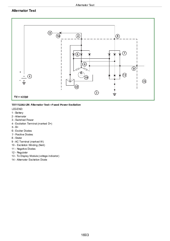
Alternator Test…1647
Controller Area Network (CAN) Circuit Test…1651
Controller Area Network (CAN) Resistor Test…1669
Section 9020: Power Train…1676
Group 05: Theory of Operation…1676
Transmission Control System…1680
Torque Converter Operation…1681
Transmission Clutch Engagement…1682
Transmission Retarder Operation…1688
Transmission Inter-Axle Differential Lock (IDL) Operation…1691
Axle Operation…1693
Cross-Axle Differential Lock (CDL) Operation…1696
Service Brake System Operation…1699
Park Brake Operation…1702
Axle Cooling System Operation—If Equipped…1704
Suspension System Operation…1706
Group 10: System Diagrams…1676
Transmission Cross Sectional Diagram…1711
Transmission System Schematic…1714
Transmission External Components…1716
Power Train Component Location…1718
Axle Cooling System Component Location…1719
Group 15: Diagnostic Information…1676
Axle Oil Leaking…1724
Axle Assembly Noisy…1727
Axle Oil Overheating…1729
Cross-Axle Differential Lock (CDL) Does Not Work…1734
Inter-Axle Differential Lock (IDL) Does Not Work…1737
Auto Differential Lock (ADL) Does Not Work…1740
Service Brake Excessive Wear…1743
Poor or No Service Brake…1745
Time Between Service Brake Accumulator Charging Cycles Too Short…1748
Service Brake Noise and Vibration…1751
Service Brakes Do Not Fully Release…1753
Park Brake Does Not Release…1755
Park Brake Will Not Hold…1758
Machine Will Not Move…1761
Transmission Will Not Shift to Forward or Reverse…1764
Machine Creeps in Neutral…1766
Engine Speed Too High During Torque Converter Stall…1767
Engine Speed Too Low During Torque Converter Stall…1769
Excessive Clutch Slippage and Chatter…1771
Oil Comes Out of Transmission Oil Fill Tube…1773
Buzzing Noise From Transmission…1775
Transmission Overheating in all Gears…1777
Transmission Not Shifting Properly (Rough Shifts, Shifting at Too-Low or Too-High Speed)…1780
Transmission Will Not Make a Specific Shift…1783
Transmission Retarder Does Not Function…1786
Transmission Retarder Weak…1788
Retarder Stays on When Not Requested…1790
Transmission Retarder Too Aggressive…1792
Group 25: Tests…1677
Transmission Warm-Up Procedure…1795
JT02156A Digital Pressure/Temperature Analyzer Installation…1797
Transmission Pressure Test…1798
Transmission Clutch Drag Test…1802
Transmission Pump Flow Test…1804
Transmission Oil Cooler Restriction Test…1806
Transmission Oil Cooler Thermal Bypass Valve Temperature Test…1808
Transmission Oil Cooler Thermal Bypass Valve Pressure Test…1811
Torque Converter—Inlet Pressure Test…1813
Torque Converter—Inlet Flow Test and Relief Pressure Test…1815
Torque Converter Stall Test…1819
Torque Converter Stator Tests…1821
Torque Converter Lockup Test…1823
Electronic Clutch Calibration…1825
Service Brake Accumulator Pressure Regulator Valve Test and Adjustment…1827
Service Brake Accumulator Pressure Sensor and Service Brake Accumulator Charge Test…1829
Front and Rear Service Brake Accumulators Pressure Test and Charge Procedure…1831
Service Brake Inspection…1834
Service Brake Valve Test…1837
Electronic Brake Valve (EBV) Test…1839
Service Brake Seal Leakage Test…1841
Axle Cooling Pump Pressure Test and Flow Test…1845
Priming Axle Oil Cooling Motors…1851
Park Brake Test…1853
Park Brake Pressure Test…1854
Park Brake Pad Thickness Check…1856
Park Brake Adjustment…1857
Strut Accumulator Pressure Test and Charge Procedure…1859
Cross-Axle Differential Lock (CDL) Pressure Test…1862
Inter-Axle Differential Lock (IDL) Pressure Test…1864
Transmission Oil Sampling Procedure…1866
Axle Oil Sampling Procedure…1867
Section 9025: Hydraulic System…1868
Group 05: Theory of Operation…1868
Hydraulic System Operation…1873
Main Hydraulic Pump Operation…1876
Main Hydraulic Pump Load Sense Operation…1878
Hydraulic Load Sense Generation Circuit Operation…1881
Steering and Secondary Steering System Operation…1885
Steering Valve Operation…1889
Secondary Steering Pump Operation…1891
Front Hydraulic System Manifold Operation…1893
Rear Hydraulic System Manifold Operation…1898
Fan Drive System Operation…1902
Group 10: System Diagrams…1868
Hydraulic Schematic Symbols…1910
Hydraulic Designators…1914
Hydraulic System Schematic…1915
Hydraulic System Component Location…1918
Hydraulic Fan System Component Location…1920
Hydraulic Steering System Component Location…1922
Hydraulic Dump System Component Location…1924
Hydraulic Brake System Component Location…1925
Group 15: Diagnostic Information…1868
No Hydraulic Functions…1868
All Hydraulic Functions Slow…1868
Hydraulic Oil Overheats…1868
Main Hydraulic Pump Noisy…1868
Dump Body Will Not Rise…1868
Dump Body Will Not Lower…1948
Cab Tilt Manifold Does Not Lift Cab…1868
Hydraulic Fan Motor Not Working…1868
Hydraulic Fan Runs at Full Speed…1868
Slow or No Steering Function…1868
Constant Steering Needed to Maintain Straight Travel…1869
Steering Erratic…1869
Steering Soft or Spongy…1869
Steering Wheel Free Play…1869
Steering Locks Up…1869
Steering Wheel Turns by Itself…1869
Machine Turns in Opposite Direction as Steering Wheel…1869
Machine Turns With Steering Valve in Neutral…1869
Suspension System Not Working…1869
Group 20: Adjustments…1869
Cab Tilt Circuit Bleed Procedure…1987
Group 25: Tests…1869
JT02156A Digital Pressure and Temperature Analyzer Kit Installation…1990
Hydraulic System Warm-Up Procedure…1991
Cycle Time Test…1993
Hydraulic System Deaeration…1995
Main Hydraulic Pump Pressure Test and Adjustment…1997
Dump Body Manual Lowering and Bin Tip Circuit Pressure Relieving Procedure…2001
Priority Valve Test…2003
Steering Load Sense Relief Valve Test and Adjustment…2004
Steering Cylinder Leakage Test…2006
Hydraulic Fan Circuit Flow Test…2008
Section 9031: Heating and Air Conditioning…2012
Group 05: Theory of Operation…2012
Air Conditioning System Cycle of Operation…2015
Group 10: System Diagrams…2012
Heating and Air Conditioning System Component Location…2018
Group 15: Diagnostic Information…2012
Air Conditioning System Does Not Operate…2012
Air Conditioning System Does Not Cool Interior of Cab…2012
Air Conditioning System Runs Constantly, Too Cold…2012
Heating System Does Not Operate…2012
Heating System Does Not Warm Interior of Cab…2012
Interior Windows Continue to Fog…2012
Group 25: Tests…2012
R134a Refrigerant Cautions and Proper Handling…2043
R134a Oil Charge Capacity…2044
R134a Refrigerant Charge Capacity…2045
Heater and Air Conditioner Operational Checks…2046
Air Conditioner Compressor Clutch Test…2050
R134a Refrigerant Leak Test…2051
R134a Refrigerant Hoses and Tubing Inspection…2052
Air Conditioning System Test…2053
Air Conditioner Freeze Control Sensor Test…2056
Operating Pressure Diagnostic Chart…2058

John Deere 260E and 310E Articulated Dump Truck Diagnosis and Test Service Technical Manual (TM14455X019)


INSTANT DOWNLOAD

Posted on

John Deere 260E and 310E Articulated Dump Truck Repair Service Manual (TM14459X019)


INSTANT DOWNLOAD


Complete Repair Service Technical Manual for John Deere 260E and 310E Articulated Dump Trucks, with all the workshop information to maintain, repair, and rebuild like professional mechanics.

John Deere 260E and 310E Articulated Dump Truck workshop technical manual (repair) includes:
* Numbered table of contents easy to use so that you can find the information you need fast.
* Detailed sub-steps expand on repair procedure information
* Numbered instructions guide you through every repair procedure step by step.
* Notes, cautions and warnings throughout each chapter pinpoint critical information.
* Bold figure number help you quickly match illustrations with instructions.
* Detailed illustrations, drawings and photos guide you through every procedure.
* Enlarged inset helps you identify and examine parts in detail.

TM14459X19 English – John Deere 260E and 310E Articulated Dump Truck Repair Technical Manual.pdf

tm14459x028 French – Camions-bennes articulés 260E et 310E

tm14459x063 Spanish – Volquetes articulados 260E y 310E

PRODUCT DETAILS:
Total Pages: 681 pages
File Format: PDF (bookmarked, ToC, Searchable, Printable)
Language: English

TABLE OF CONTENTS
Section 00: General Information….14
Group 0001: Safety….14
Information for European Union Directives and Eurasian Economic Union Technical Regulations Compliance….22
Recognize Safety Information….27
Follow Safety Instructions….28
Operate Only If Qualified….29
Wear Protective Equipment….30
Protect Against Noise….31
Avoid Unauthorized Machine Modifications….32
Inspect Machine….33
Stay Clear of Moving Parts….34
Avoid High-Pressure Fluids….35
Avoid High-Pressure Oils….36
Work In Ventilated Area….37
Avoid Static Electricity Risk When Refueling….38
High Debris Applications….40
Prevent Fires….41
In Case of Machine Fire….43
Prevent Battery Explosions….44
Handle Chemical Products Safely….45
Handle Starting Fluid Safely….46
Decommissioning — Proper Recycling and Disposal of Fluids and Components….47
Prepare for Emergencies….48
Clean Debris from Machine….49
Add Cab Guarding for Special Uses….50
Use Steps and Handholds Correctly….51
Start Only From Operator's Seat….52
Use and Maintain Seat Belt….53
Heated and Ventilated Operator’s Seat….54
Prevent Unintended Machine Movement….55
Avoid Work Site Hazards….56
Avoid Power Lines….58
Keep Riders Off Machine….59
Avoid Backover Accidents….60
Avoid Machine Tip Over and Machine Damage….61
Operating on Slopes….62
Operating or Traveling On Public Roads….63
Inspect and Maintain ROPS….64
Travel Safely….65
Prevent Acid Burns….66
Add and Operate Attachments Safely….68
Park and Prepare for Service Safely….69
Service Machines Safely….70
Service Cooling System Safely….71
Service Accumulator Systems Safely….72
Remove Paint Before Welding or Heating….73
Make Welding Repairs Safely….74
Drive Metal Pins Safely….75
Service Tires Safely….76
Use Proper Lifting Equipment….77
Group 0003: Torque Values….15
Metric Bolt and Cap Screw Torque Values….80
Additional Metric Cap Screw Torque Values….82
Unified Inch Bolt and Cap Screw Torque Values….84
Service Recommendations for 37° Flare and 30° Cone Seat Connectors….87
Service Recommendations for O-Ring Boss Fittings….89
O-Ring Boss Fittings in Aluminum Housing Service Recommendations—Excavators….91
Service Recommendations for Flared Connections—Straight or Tapered Threads….93
Service Recommendations for Flat Face O-Ring Seal Fittings….95
O-Ring Face Seal Fittings With SAE Inch Hex Nut and Stud End for High-Pressure Service Recommendations….97
O-Ring Face Seal Fittings With Metric Hex Nut and Stud End for Standard Pressure Service Recommendations….99
O-Ring Face Seal Fittings With Metric Hex Nut and Stud End for High-Pressure Service Recommendations….102
Service Recommendations for Metric Series Four Bolt Flange Fitting….104
Service Recommendations For Inch Series Four Bolt Flange Fittings….106
Inch Series Four Bolt Flange Fitting for High-Pressure Service Recommendations….108
Service Recommendations For Non-Restricted Banjo (Adjustable) Fittings….110
Service Recommendations For O-Ring Boss Fittings With Shoulder….113
Metric 24° O-Ring Seal DIN 20078 Service Recommendations….116
Section 01: Wheels….120
Group 0100: Removal and Installation….120
Wheel Remove and Install….123
Tire Remove and Install….125
Section 02: Axles and Suspension Systems….128
Group 0200: Removal and Installation….128
Front Axle Remove and Install….133
Middle or Rear Axle Remove and Install….137
Group 0225: Input Drive Shafts and U-Joints….128
Transmission-to-Front Axle Drive Shaft or Transmission-to-Oscillation Joint Drive Shaft Remove and Install….148
Oscillation Joint Drive Shaft Remove and Install….148
Park Brake-to-Middle Axle Drive Shaft Remove and Install….152
Middle Axle-to-Rear Axle Drive Shaft Remove and Install….154
Group 0242: Axle Mounting Parts….128
Front Suspension Strut Remove and Install….159
Axle Links and Stabilizers Remove and Install….162
Axle Link, Stabilizer, and Strut Bushing Replacement….165
Front Axle Pivot Disassemble and Assemble….168
Walking Beam Remove and Install….171
Walking Beam Bushing Remove and Install….176
Middle and Rear Axle Rubber Mount Remove and Install….178
Strain Gauge Remove and Install….180
Group 0250: Axle Shaft, Bearings, and Reduction Gears….128
Axle Planetary Pinion/Service Brake Housing Disassemble and Assemble….209
Axle Housing and Input Drive Disassemble and Assemble….235
Differential Disassemble and Assemble….256
Gear Tooth Contact Pattern Check….270
Group 0260: Hydraulic System….128
Front Axle Pump Remove and Install….274
Middle and Rear Axle Pump Remove and Install….275
Section 03: Transmission….276
Group 0300: Removal and Installation….276
Transmission Remove and Install….284
Group 0325: Input Drive Shafts and U-Joints….276
Engine-to-Transmission Drive Shaft Remove and Install….294
Group 0350: Gear, Shafts, and Power Shift Clutches….276
Transmission Speed Sensors Remove and Install….303
Group 0360: Hydraulic System….276
Transmission Oil Cooler Thermal Bypass Valve Remove and Install….310
Transmission Control Valve Remove and Install….311
Torque Converter Remove and Install….313
Clutch Control Valve Remove and Install….314
Retarder Control Valve Remove and Install….315
Oil Pump Remove and Install….316
Transmission Retarder Remove and Install….317
Transmission Control Valve Disassemble and Assemble….325
Clutch Control Valve Disassemble and Assemble….331
Retarder Control Valve Disassemble and Assemble….337
Oil Pump Disassemble and Assemble….342
Transmission Retarder Disassemble and Assemble….344
Section 04: Engine….355
Group 0400: Removal and Installation….355
John Deere Engine….357
Engine Remove and Install….358
Engine Crankshaft Damper Remove and Install….371
Section 05: Engine Auxiliary System….372
Group 0505: Cold Weather Starting Aids….372
Cold Start Aid—Starting Fluid Nozzle Remove and Install—If Equipped….375
Cold Start Aid—Starting Fluid Solenoid Remove and Install—If Equipped….377
Cold Start Aid—Block Heater Remove and Install—If Equipped….379
Diesel Fired Coolant Heater (DFCH) Remove and Install—If Equipped….382
Group 0510: Cooling Systems….372
Charge Air Cooler Remove and Install….388
Radiator Remove and Install….391
Hydraulic Oil Cooler Remove and Install….394
Transmission Oil Cooler Remove and Install….396
Fuel Cooler Remove and Install….400
Axle Oil Coolers Remove and Install….402
Group 0520: Intake System….372
Air Cleaner Remove and Install….405
Group 0530: External Exhaust Systems….372
Exhaust Tube Remove and Install….409
Dump Body Heater Pipe Remove and Install….412
Dump Body Heater Exhaust Collar Adjust….414
Group 0560: External Fuel Supply Systems….372
Fuel Tank Remove and Install….421
Fast Fill Fuel System Disassemble and Assemble—If Equipped….426
Section 07: Damper Drive….428
Group 0752: Elements….428
Output Damper Remove and Install….432
Section 09: Steering System….435
Group 0930: Secondary Steering….435
Secondary Steering Pump Remove and Install….438
Group 0960: Hydraulic System….435
Steering Valve Remove and Install….443
Steering Cylinder Remove and Install….446
Steering Bushing Replacement….450
Section 10: Service Brakes….451
Group 1011: Active Elements….451
Service Brake Assembly Remove and Install….453
Group 1060: Hydraulic System….451
Bleed Service Brake….456
Service Brake Accumulator Remove and Install….458
Service Brake Valve Remove and Install….460
Service Brake Valve Disassemble and Assemble….462
Section 11: Park Brake….466
Group 1111: Active Elements….466
Park Brake Pads Remove and Install….469
Park Brake Caliper Remove and Install….471
Park Brake Disc Remove and Install….474
Park Brake Chamber Remove and Install….476
Section 16: Electrical System….478
Group 1600: Removal and Installation….478
TPM—Tire Pressure Sensor Remove and Install….481
Controllers Remove and Install….483
Connector Repair Information….485
Alternator Remove and Install….486
Section 17: Frame or Supporting Structure….488
Group 1740: Frame Installation….488
Welding On Machine….490
Front and Rear Frames Separate….491
Articulation Frame Remove and Install….497
Articulation Frame Bearings Disassemble and Assemble….500
Articulation Frame Bearings Adjust….502
Oscillation Joint Disassemble and Assemble….506
Section 18: Operator's Station….513
Group 1810: Operator Enclosure….513
Cab Remove and Install….520
Cab Mount Remove and Install….526
Cab Tilt Pump and Cylinder Remove and Install….530
Cab Tilt Cylinder Disassemble and Assemble….534
Windowpanes Remove and Install….535
Window Wiper and Wiper Motor Remove and Install….537
Group 1821: Seat and Seat Belt….513
Operator’s Seat Remove and Install….546
Seat Belt Remove and Install….549
Group 1830: Heating and Air Conditioning….513
R134a Refrigerant Cautions and Proper Handling….551
R134a Refrigerant Oil Information….552
R134a Refrigerant Recovery, Recycling, and Charging Station Installation Procedure….554
Recover R134a Refrigerant….556
Flush and Purge Air Conditioning System….557
Evacuate R134a System….560
Charge R134a System….562
Compressor Remove and Install….564
Condenser Remove and Install….567
High/Low-Pressure Sensor Remove and Install….569
Receiver-Dryer Remove and Install….572
Expansion Valve Remove and Install….574
Heater Core and Evaporator Core Remove and Install….577
Freeze Control Sensor Remove and Install….581
Blower Motor Assembly Remove and Install….584
Section 19: Sheet Metal and Styling….586
Group 1910: Hood or Engine Enclosure….586
Hood Remove and Install….591
Engine Service Door Remove and Install….595
Group 1927: Fenders….586
Fender Remove and Install….600
Section 21: Main Hydraulic System….603
Group 2160: Hydraulic System….603
Main Hydraulic Pump Remove and Install….607
Hydraulic Reservoir Remove and Install….610
Front Hydraulic System Manifold Remove and Install….614
Front Hydraulic System Manifold Disassemble and Assemble….617
Rear Hydraulic System Manifold Remove and Install….622
Rear Hydraulic System Manifold Disassemble and Assemble….625
Hydraulic Fan Motor Left Side Remove and Install….629
Hydraulic Fan Motor Right Side Remove and Install….633
Left Hydraulic Fan Pump Remove and Install….637
Right Hydraulic Fan Pump Remove and Install….640
Hydraulic Component Failure Cleanup Procedure….641
General Oil Cleanup Procedure….644
Section 35: Haulage Device….647
Group 3540: Frames….647
Dump Body Remove and Install….650
Dump Body Align….652
Tailgate Remove and Install….654
Group 3560: Hydraulic System….647
Dump Body Lift Cylinder Remove and Install….663
Section 99: Dealer Fabricated Tools….666
Group 9900: Dealer Fabricated Tools….666
DFT1344 Supports….668
DFT1344A Supports….669
DFT1187 Bearing Driver….670
DFT1199 Bushing Pusher….671
DFT1200 Bushing Driver….672
JT38031 Bushing Driver….673
JT38058 Bushing Driver….674
JT38060 Bushing Driver….675
JT38064 Bushing Driver….676
JT38073 Bushing Driver….677
DFT1388 Hood Isolator Compression Test Tool….678

John Deere 260E and 310E Articulated Dump Truck Repair Service Manual (TM14459X019)


INSTANT DOWNLOAD


Posted on

John Deere 260E and 310E Articulated Dump Truck Diagnosis and Test Service Technical Manual (TM14458X019)


INSTANT DOWNLOAD


Complete Diagnosis & Tests Technical Manual with electrical wiring diagrams for John Deere 260E and 310E Articulated Dump Truck, with workshop information to maintain, diagnose, and rebuild like professional mechanics.

John Deere 260E and 310E Articulated Dump Truck workshop Diagnosis & Tests technical manual includes:
* Numbered table of contents easy to use so that you can find the information you need fast.
* Detailed sub-steps expand on repair procedure information
* Numbered instructions guide you through every repair procedure step by step.
* Troubleshooting and electrical service procedures are combined with detailed wiring diagrams for ease of use.
* Notes, cautions and warnings throughout each chapter pinpoint critical information.
* Bold figure number help you quickly match illustrations with instructions.
* Detailed illustrations, drawings and photos guide you through every procedure.
* Enlarged inset helps you identify and examine parts in detail.

TM14458X019 English – John Deere 260E and 310E Articulated Dump Truck Operation and Test Technical Manual.pdf
tm14458x028 French – Fonctionnement et contrôles des camions-benne articulés 260E et 310E
tm14458x063 Spanish – Volquetes articulados 260E y 310E Funcionamiento y pruebas

PRODUCT DETAILS:
Total Pages: 2,012 pages
File Format: PDF (bookmarked, ToC, Searchable, Printable)
Language: English

TABLE OF CONTENTS
Section 9000: General Information……37
Group 01: Safety……37
Information for European Union Directives and Eurasian Economic Union Technical Regulations Compliance……44
Recognize Safety Information……49
Follow Safety Instructions……50
Operate Only If Qualified……51
Wear Protective Equipment……52
Protect Against Noise……53
Avoid Unauthorized Machine Modifications……54
Inspect Machine……55
Stay Clear of Moving Parts……56
Avoid High-Pressure Fluids……57
Avoid High-Pressure Oils……58
Work In Ventilated Area……59
Avoid Static Electricity Risk When Refueling……60
High Debris Applications……62
Prevent Fires……63
In Case of Machine Fire……65
Prevent Battery Explosions……66
Handle Chemical Products Safely……67
Handle Starting Fluid Safely……68
Decommissioning — Proper Recycling and Disposal of Fluids and Components……69
Prepare for Emergencies……70
Clean Debris from Machine……71
Add Cab Guarding for Special Uses……72
Use Steps and Handholds Correctly……73
Start Only From Operator's Seat……74
Use and Maintain Seat Belt……75
Heated and Ventilated Operator’s Seat……76
Prevent Unintended Machine Movement……77
Avoid Work Site Hazards……78
Avoid Power Lines……80
Keep Riders Off Machine……81
Avoid Backover Accidents……82
Avoid Machine Tip Over and Machine Damage……83
Operating on Slopes……84
Operating or Traveling On Public Roads……85
Inspect and Maintain ROPS……86
Travel Safely……87
Prevent Acid Burns……88
Add and Operate Attachments Safely……90
Park and Prepare for Service Safely……91
Service Machines Safely……92
Service Cooling System Safely……93
Service Accumulator Systems Safely……94
Remove Paint Before Welding or Heating……95
Make Welding Repairs Safely……96
Drive Metal Pins Safely……97
Service Tires Safely……98
Use Proper Lifting Equipment……99
Section 9001: Diagnostics……100
Group 01: General Information……100
Diagnostic Trouble Code Designations……124
Group 10: Transmission Control Unit (TCU) Diagnostic Trouble Codes……100
523000.01 – Controller Power Source Fault……100
523000.03 – Controller Power Source Fault……100
523000.04 – Unswitched Power Circuit Fault……100
523001.01 – Unswitched Power Fault……100
523010.03 – Sensor Supply Circuit Fault……100
523010.04 – Sensor Supply Circuit Fault……100
523011.04 – Internal Controller Supply Circuit Fault……100
523020.03 – Sensor Supply Circuit Fault……100
523020.04 – Sensor Supply Circuit Fault……100
523020.06 – Sensor Supply Circuit Fault……100
523021.03 – Sensor Supply Circuit Fault……100
523021.04 – Sensor Supply Circuit Fault……100
523021.06 – Sensor Supply Circuit Fault……100
523022.03 – Sensor Supply Circuit Fault……100
523022.04 – Sensor Supply Circuit Fault……100
523022.06 – Sensor Supply Circuit Fault……100
523030.03 – Controller Valve Power Supply Circuit Fault……100
523030.04 – Controller Valve Power Supply Circuit Fault……100
523030.06 – Controller Power Source Fault……100
523031.03 – Controller Valve Power Supply Circuit Fault……100
523031.04 – Controller Valve Power Supply Circuit Fault……100
523031.06 – Controller Power Source Fault……100
523040.00 – Controller Temperature High……100
523040.02 – Internal Controller Temperature High……100
523045.12 – Controller Fault……100
523046.12 – Controller Fault……100
523047.12 – Controller Fault……100
523048.12 – Controller Fault……100
523049.12 – Controller Fault……101
523100.02 – Turbine Speed Sensor Fault……101
523100.03 – Turbine Speed Sensor Fault……101
523100.06 – Turbine Speed Sensor Fault……101
523100.07 – Turbine Speed Sensor Fault……101
523100.08 – Turbine Speed Sensor Fault……101
523100.09 – Turbine Speed Sensor Fault……101
523100.11 – Turbine Speed Sensor Fault……101
523105.02 – Unknown Connection……101
523105.03 – Internal Speed Sensor Fault……101
523105.06 – Internal Speed Sensor Fault……101
523105.07 – Internal Speed Sensor Fault……101
523105.08 – Internal Speed Sensor Fault……101
523105.09 – Internal Speed Sensor Fault……101
523105.11 – Internal Speed Sensor Fault……101
523110.02 – Unknown Connection……101
523110.03 – Internal Speed Sensor Fault……101
523110.06 – Internal Speed Sensor Fault……101
523110.07 – Internal Speed Sensor Fault……101
523110.08 – Internal Speed Sensor Fault……101
523110.09 – Internal Speed Sensor Fault……101
523110.11 – Internal Speed Sensor Fault……101
523115.02 – Unknown Connection……101
523115.03 – Output Speed Sensor Fault……101
523115.06 – Output Speed Sensor Fault……101
523115.07 – Output Speed Sensor Fault……101
523115.08 – Output Speed Sensor Fault……101
523115.09 – Output Speed Sensor Fault……101
523115.11 – Output Speed Sensor Fault……101
523125.02 – Transmission Invalid Component Circuit Fault……101
523130.02 – Unknown Connection……101
523140.02 – Unknown Connection……101
523140.03 – Transmission Sump Temperature Sensor Fault……101
523140.05 – Transmission Sump Temperature Sensor Fault……102
523140.06 – Transmission Sump Temperature Sensor Fault……102
523145.02 – Unknown Connection……102
523145.03 – Retarder Temperature Sensor Fault……102
523145.05 – Retarder Temperature Sensor Fault……102
523145.06 – Retarder Temperature Sensor Fault……102
523150.02 – Unknown Connection……102
523155.02 – Unknown Connection……102
523155.03 – Transmission Oil Filter Fault……102
523155.04 – Transmission Oil Filter Fault……102
523155.06 – Transmission Oil Filter Fault……102
523200.00 – Clutch A Slip……102
523200.02 – Unknown Connection……102
523200.03 – Controller Valve Power Supply Circuit Fault……102
523200.05 – Controller Valve Power Supply Circuit Fault……102
523200.06 – Controller Valve Power Supply Circuit Fault……102
523200.08 – Clutch A Proportional Valve Circuit Fault……102
523205.00 – Clutch B Slip……102
523205.02 – Unknown Connection……102
523205.03 – Controller Valve Power Supply Circuit Fault……102
523205.05 – Controller Valve Power Supply Circuit Fault……102
523205.06 – Controller Valve Power Supply Circuit Fault……102
523205.08 – Clutch B Proportional Valve Circuit Fault……102
523210.00 – Clutch C Slip……102
523210.02 – Unknown Connection……102
523210.03 – Clutch C Proportional Valve Circuit Fault……102
523210.05 – Clutch C Proportional Valve Circuit Fault……102
523210.06 – Clutch C Proportional Valve Circuit Fault……102
523210.08 – Clutch C Proportional Valve Circuit Fault……102
523215.00 – Clutch D Slip……102
523215.02 – Unknown Connection……102
523215.03 – Clutch D Proportional Valve Circuit Fault……102
523215.05 – Clutch D Proportional Valve Circuit Fault……102
523215.06 – Clutch D Proportional Valve Circuit Fault……103
523215.08 – Clutch D Proportional Valve Circuit Fault……103
523220.00 – Clutch R Slip……103
523220.02 – Unknown Connection……103
523220.03 – Clutch R Proportional Valve Circuit Fault……103
523220.05 – Clutch R Proportional Valve Circuit Fault……103
523220.06 – Clutch R Proportional Valve Circuit Fault……103
523220.08 – Clutch R Proportional Valve Circuit Fault……103
523225.00 – Clutch F Slip……103
523225.02 – Unknown Connection……103
523225.03 – Clutch F Proportional Valve Circuit Fault……103
523225.05 – Clutch F Proportional Valve Circuit Fault……103
523225.06 – Clutch F Proportional Valve Circuit Fault……103
523225.08 – Clutch F Proportional Valve Circuit Fault……103
523230.00 – Clutch V Slip……103
523230.02 – Unknown Connection……103
523230.03 – Clutch V Proportional Valve Circuit Fault……103
523230.05 – Clutch V Proportional Valve Circuit Fault……103
523230.06 – Clutch V Proportional Valve Circuit Fault……103
523230.08 – Clutch V Proportional Valve Circuit Fault……103
523235.00 – Clutch E Slip……103
523235.02 – Unknown Connection……103
523235.03 – Clutch E Proportional Valve Circuit Fault……103
523235.05 – Clutch E Proportional Valve Circuit Fault……103
523235.06 – Clutch E Proportional Valve Circuit Fault……103
523235.08 – Clutch E Proportional Valve Circuit Fault……103
523240.00 – Transmission Lockup Clutch Slip……103
523240.02 – Unknown Connection……103
523240.03 – Torque Converter Proportional Valve Circuit Fault……103
523240.05 – Torque Converter Proportional Valve Circuit Fault……103
523240.06 – Torque Converter Proportional Valve Circuit Fault……103
523240.08 – Torque Converter Proportional Valve Circuit Fault……103
523245.02 – Unknown Connection……103
523245.03 – Retarder Proportional Valve Circuit Fault……104
523245.05 – Retarder Proportional Valve Circuit Fault……104
523245.06 – Retarder Proportional Valve Circuit Fault……104
523245.08 – Retarder Proportional Valve Circuit Fault……104
523250.01 – Controller Area Network (CAN) Message Invalid or Time-Out……104
523250.02 – Unknown Connection……104
523250.03 – Diff Lock Proportional Valve Circuit Fault……104
523250.05 – Diff Lock Proportional Valve Circuit Fault……104
523250.06 – Diff Lock Proportional Valve Circuit Fault……104
523250.08 – Diff Lock Proportional Valve Circuit Fault……104
523300.00 – Transmission Sump Oil Temperature High……104
523300.16 – Transmission Sump Oil Temperature High……104
523301.00 – Retarder Oil Temperature High……104
523301.16 – Retarder Oil Temperature High……104
523302.00 – Torque Converter Oil Temperature High……104
523302.16 – Torque Converter Oil Temperature High……104
523304.00 – Transmission Oil Filter Fault……104
523305.00 – Transmission Oil Filter Restricted……104
523310.00 – Transmission Input Torque High……104
523320.15 – Transmission Output Speed High……104
523355.00 – Forward Clutch Reversal Temperature Limit Exceeded Severely……104
523356.00 – Reverse Clutch Reversal Temperature Limit Exceeded Severely……104
523360.09 – Internal Controller Error……104
523371.00 – Driveline Engagement Protection……104
523400.09 – Communication System Message Missing……104
523401.09 – Communication System Message Missing……104
523402.09 – Communication System Message Missing……104
523403.09 – Communication System Message Missing……104
523410.09 – Communication System Message Missing……104
523413.09 – Communication System Message Missing……104
523414.09 – Communication System Message Missing……104
523415.09 – Communication System Message Missing……104
523416.09 – Communication System Message Missing……104
523417.09 – Communication System Message Missing……105
523418.09 – Communication System Message Missing……105
523419.09 – Communication System Message Missing……105
523420.09 – Communication System Message Missing……105
523424.09 – Communication System Message Missing……105
523426.09 – Communication System Message Missing……105
523427.09 – Communication System Message Missing……105
523470.19 – Operation Mode Fault……105
523471.19 – Transmission Command Fault……105
523474.19 – Difflock Command Fault……105
523475.19 – Torque Converter Lockup Command Fault……105
523476.19 – Retarder Command Fault……105
523480.09 – Machine Configuration Invalid……105
523481.00 – Testmode Not Active……105
523500.00 – Transmission Input Speed High……105
523501.00 – Engine Speed Limitation Fault……105
523502.00 – Engine Speed Demand Fault……105
523503.00 – Engine Torque Limitation Fault……105
523504.00 – Engine Torque Demand Fault……105
523505.00 – Transmission Protection……105
523506.00 – Engine Brake Without Request……105
523600.00 – Transmission Protection……105
523600.01 – Transmission Protection……105
523600.02 – Transmission Protection……105
523600.03 – Transmission Protection……105
523600.04 – Transmission Protection……105
523600.05 – Transmission Protection……105
523600.07 – Transmission Protection……105
523600.09 – Transmission Protection……105
523600.10 – Transmission Protection……105
523601.00 – Transmission Protection……105
523602.00 – Transmission Protection……105
523603.00 – Transmission Protection……105
523650.00 – Neutral Selected While in Motion……106
Group 20: Engine Control Unit (ECU) Diagnostic Trouble Codes……106
000091.03 – Throttle Input……106
000091.04 – Throttle Input……106
000237.02 – VIN Security Data Invalid……106
000237.13 – VIN Option Code Security Data Conflict……106
000237.31 – VIN Security Data Missing……106
001321.05 – Starter Relay……106
001321.06 – Starter Relay……106
001321.09 – Starter Relay……106
001321.16 – Starter Relay……106
001321.31 – Starter Relay……106
002003.09 – Communication System……106
002033.09 – Communication System……106
003353.31 – Alternator……106
003587.05 – Ether Starting Aid Circuit Fault……106
003587.06 – Ether Starting Aid Circuit Fault……106
524225.31 – Engine Speed Detected Without Start Signal……106
Group 30: Vehicle Control Unit (VCU) Diagnostic Trouble Codes……106
000096.03 – Fuel Level Sensor Circuit Fault……106
000096.04 – Fuel Level Sensor Circuit Fault……106
000116.03 – Rear Brake Sensor Circuit Fault……106
000116.04 – Rear Brake Sensor Circuit Fault……106
000117.01 – Rear Brake Charge Pressure Extremely Low……106
000117.03 – Rear Brake Charge Pressure Sensor Circuit Fault……106
000117.04 – Rear Brake Charge Pressure Sensor Circuit Fault……106
000237.02 – Vehicle Identification Conflict……106
000237.13 – Vehicle Identification Fault……106
000237.31 – Communication Fault……106
000619.03 – Brake Solenoid Circuit Fault……106
000619.05 – Brake Solenoid Circuit Fault……106
000619.06 – Brake Solenoid Circuit Fault……106
000628.12 – Control Unit Programming……106
000629.12 – Engine Control Unit Fault……107
000639.12 – Communication System Message Missing……107
000639.14 – Communication System……107
000746.07 – Differential Lock Clutches Worn……107
001045.04 – Brake Light Switch Circuit Fault……107
001071.03 – Fan Speed Solenoid Circuit Fault……107
001071.04 – Fan Speed Solenoid Circuit Fault……107
001071.05 – Fan Speed Solenoid Circuit Fault……107
001071.06 – Fan Speed Solenoid Circuit Fault……107
001120.03 – Articulation Angle Sensor Circuit Fault……107
001120.04 – Articulation Angle Sensor Circuit Fault……107
001120.07 – Articulation Angle Sensor Circuit Fault……107
001231.14 – CAN 2 Bus Off……107
001638.00 – Hydraulic Oil Temperature High……107
001638.03 – Hydraulic Oil Temperature Sensor Circuit Fault……107
001638.04 – Hydraulic Oil Temperature Sensor Circuit Fault……107
001639.08 – Left Cooling Fan Speed Fault……107
001713.01 – Hydraulic Oil Filter Restricted……107
001713.03 – Hydraulic Oil Filter Restriction Switch Circuit Fault……107
001713.16 – Hydraulic Oil Filter Restriction Switch Circuit Fault……107
002000.09 – Communication System Message Missing……107
002003.09 – Communication System Message Missing……107
002038.09 – Communication System Message Missing……107
002051.09 – Communication System Message Missing……107
002072.09 – Communication System Message Missing……107
002078.09 – Communication System Message Missing……107
002142.09 – Communication System Message Missing……107
002143.09 – Communication System Message Missing……107
002213.09 – Communication System Message Missing……107
002251.09 – Communication System Message Missing……107
002347.04 – Hi Beam Switch Circuit Fault……107
002348.03 – Hi Beam Light Circuit Fault……107
002348.05 – Hi Beam Light Circuit Fault……107
002348.06 – Hi Beam Light Circuit Fault……108
002350.03 – Low Beam Light Circuit Fault……108
002350.05 – Low Beam Light Circuit Fault……108
002350.06 – Low Beam Light Circuit Fault……108
002355.03 – Front Cab Lights Circuit Fault……108
002355.05 – Front Cab Lights Circuit Fault……108
002355.06 – Front Cab Lights Circuit Fault……108
002368.03 – Left Turn Signal Circuit Fault……108
002368.05 – Left Turn Signal Circuit Fault……108
002368.06 – Left Turn Signal Circuit Fault……108
002370.03 – Right Turn Signal Circuit Fault……108
002370.05 – Right Turn Signal Circuit Fault……108
002370.06 – Right Turn Signal Circuit Fault……108
002386.03 – Rotary Beacon Circuit Fault……108
002386.05 – Rotary Beacon Circuit Fault……108
002386.06 – Rotary Beacon Circuit Fault……108
002598.03 – Artic Reverse Light Circuit Fault……108
002598.05 – Artic Reverse Light Circuit Fault……108
002598.06 – Artic Reverse Light Circuit Fault……108
002641.03 – Horn Circuit Fault……108
002641.05 – Horn Circuit Fault……108
002641.06 – Horn Circuit Fault……108
002642.03 – Heated Mirror Circuit Fault……108
002642.05 – Heated Mirror Circuit Fault……108
002642.06 – Heated Mirror Circuit Fault……108
002833.31 – Movement While Park Brake Applied……108
002930.31 – Brake Pressures Very Different……108
003509.03 – Sensor Supply Circuit Fault……108
003509.04 – Sensor Supply Circuit Fault……108
003510.03 – Sensor Supply Circuit Fault……108
003510.04 – Sensor Supply Circuit Fault……108
003511.03 – Sensor Supply Circuit Fault……108
003511.04 – Sensor Supply Circuit Fault……108
004086.03 – Load Sense Pressure Sensor Circuit Fault……109
004086.04 – Load Sense Pressure Sensor Circuit Fault……109
004952.04 – Seat Belt Switch Short to Ground……109
005557.03 – Fan 2 Reverse Solenoid Circuit Fault……109
005557.05 – Fan 2 Reverse Solenoid Circuit Fault……109
005557.06 – Fan 2 Reverse Solenoid Circuit Fault……109
005562.08 – Right Cooling Fan Speed Fault……109
005563.03 – Fan 2 Reverse Circuit Fault……109
005563.04 – Fan 2 Reverse Circuit Fault……109
005563.05 – Fan 2 Reverse Circuit Fault……109
005563.06 – Fan 2 Reverse Circuit Fault……109
005572.03 – 12V Power Converter Circuit Fault……109
005572.04 – 12V Power Converter Circuit Fault……109
516691.03 – Under Hood Work Light Circuit Fault……109
516691.05 – Under Hood Work Light Circuit Fault……109
516691.06 – Under Hood Work Light Circuit Fault……109
516884.04 – Strut Release Button Circuit Fault……109
516885.03 – Dump Body Cylinder Rod Oil Return Solenoid Circuit Fault……109
516885.04 – Dump Body Cylinder Rod Oil Return Solenoid Circuit Fault……109
516885.05 – Dump Body Cylinder Rod Oil Return Solenoid Circuit Fault……109
516885.06 – Dump Body Cylinder Rod Oil Return Solenoid Circuit Fault……109
516886.03 – Dump Body Cylinder Head Oil Return Solenoid Circuit Fault……109
516886.04 – Dump Body Cylinder Head Oil Return Solenoid Circuit Fault……109
516886.05 – Dump Body Cylinder Head Oil Return Solenoid Circuit Fault……109
516886.06 – Dump Body Cylinder Head Oil Return Solenoid Circuit Fault……109
516940.03 – Front Right Suspension Pressure Sensor Circuit Fault……109
516940.04 – Front Right Suspension Pressure Sensor Circuit Fault……109
516941.03 – Front Left Suspension Pressure Sensor Circuit Fault……109
516941.04 – Front Left Suspension Pressure Sensor Circuit Fault……109
517989.03 – Fan 1 Relief Valve Circuit Fault……109
517989.04 – Fan 1 Relief Valve Circuit Fault……109
517989.05 – Fan 1 Relief Valve Circuit Fault……109
517989.06 – Fan 1 Relief Valve Circuit Fault……109
517990.03 – Fan 2 Relief Valve Circuit Fault……110
517990.04 – Fan 2 Relief Valve Circuit Fault……110
517990.05 – Fan 2 Relief Valve Circuit Fault……110
517990.06 – Fan 2 Relief Valve Circuit Fault……110
520329.09 – Communication System Message Missing……110
520833.03 – Body Solenoid Circuit Fault……110
520833.04 – Body Solenoid Circuit Fault……110
520833.05 – Body Solenoid Circuit Fault……110
520833.06 – Body Solenoid Circuit Fault……110
520835.01 – Mid Axle Oil Filter Restricted……110
520838.01 – Rear Axle Oil Filter Restricted……110
520841.00 – Front CDL Axle Pressure High……110
520841.01 – Front CDL Axle Pressure Low……110
520841.03 – Front CDL Pressure Sensor Circuit Fault……110
520841.04 – Front CDL Pressure Sensor Circuit Fault……110
520848.03 – Front CDL Solenoid Circuit Fault……110
520848.05 – Front CDL Solenoid Circuit Fault……110
520848.06 – Front CDL Solenoid Circuit Fault……110
520869.03 – Green OBW Light Circuit Fault……110
520869.05 – Green OBW Light Circuit Fault……110
520869.06 – Green OBW Light Circuit Fault……110
520877.03 – Red OBW Light Circuit Fault……110
520877.05 – Red OBW Light Circuit Fault……110
520877.06 – Red OBW Light Circuit Fault……110
520878.03 – Axle Cooling Cut Solenoid Circuit Fault……110
520878.05 – Axle Cooling Cut Solenoid Circuit Fault……110
520878.06 – Axle Cooling Cut Solenoid Circuit Fault……110
520889.03 – Left Strut Position Sensor Circuit Fault……110
520889.04 – Left Strut Position Sensor Circuit Fault……110
520899.03 – Right Strut Position Sensor Circuit Fault……110
520899.04 – Right Strut Position Sensor Circuit Fault……110
520911.04 – Service Light Switch Circuit Fault……110
520914.07 – Body Position Sensor Fault……110
520917.03 – Rear Left Turn Signal Circuit Fault……111
520917.05 – Rear Left Turn Signal Circuit Fault……111
520917.06 – Rear Left Turn Signal Circuit Fault……111
520918.03 – Rear Right Turn Signal Circuit Fault……111
520918.05 – Rear Right Turn Signal Circuit Fault……111
520918.06 – Rear Right Turn Signal Circuit Fault……111
520949.03 – Left Strut Solenoid Circuit Fault……111
520949.04 – Left Strut Solenoid Circuit Fault……111
520949.05 – Left Strut Solenoid Circuit Fault……111
520949.06 – Left Strut Solenoid Circuit Fault……111
520950.03 – Left Strut Solenoid Circuit Fault……111
520950.05 – Left Strut Solenoid Circuit Fault……111
520950.06 – Left Strut Solenoid Circuit Fault……111
520953.03 – Right Strut Solenoid Circuit Fault……111
520953.04 – Right Strut Solenoid Circuit Fault……111
520953.05 – Right Strut Solenoid Circuit Fault……111
520953.06 – Right Strut Solenoid Circuit Fault……111
520954.03 – Right Strut Down Circuit Fault……111
520954.05 – Right Strut Down Circuit Fault……111
520954.06 – Right Strut Down Circuit Fault……111
520957.03 – Park Brake Release Solenoid Fault……111
520957.05 – Park Brake Release Solenoid Circuit Fault……111
520957.06 – Park Brake Release Solenoid Circuit Fault……111
521157.04 – Hazard Lamp Enable Circuit Fault……111
521197.04 – Exit Light Switch Circuit Fault……111
521466.03 – Fan 1 Relief Circuit Fault……111
521466.05 – Fan 1 Relief Circuit Fault……111
521466.06 – Fan 1 Relief Circuit Fault……111
521467.03 – Fan 2 Relief Circuit Fault……111
521467.05 – Fan 2 Relief Circuit Fault……111
521467.06 – Fan 2 Relief Circuit Fault……111
521834.03 – Fan Reverse Solenoid Circuit Fault……111
521834.05 – Fan Reverse Solenoid Circuit Fault……111
521834.06 – Fan Reverse Solenoid Circuit Fault……112
521891.01 – Front Axle Oil Filter Restricted……112
521891.03 – Front Axle Oil Filter Fault……112
521891.16 – Front Axle Oil Filter Circuit Fault……112
521924.00 – Front Axle Oil Temperature High……112
521924.03 – Front Axle Temperature Sensor Circuit Fault……112
521924.04 – Front Axle Temperature Sensor Circuit Fault……112
522279.03 – Brake Control Valve Circuit Fault……112
522279.04 – Brake Control Valve Circuit Fault……112
522279.05 – Brake Control Valve Circuit Fault……112
522279.06 – Brake Control Valve Circuit Fault……112
522311.03 – Rear Washer Pump Circuit Fault……112
522311.05 – Rear Washer Pump Circuit Fault……112
522311.06 – Rear Washer Pump Circuit Fault……112
522312.03 – Front Washer Pump Circuit Fault……112
522312.05 – Front Washer Pump Circuit Fault……112
522312.06 – Front Washer Pump Circuit Fault……112
522426.10 – Rear Wiper Park Circuit Fault……112
522427.10 – Front Wiper Park Circuit Fault……112
522433.03 – Rear Wiper Low-Speed Circuit Fault……112
522433.05 – Rear Wiper Low-Speed Circuit Fault……112
522433.06 – Rear Wiper Low-Speed Circuit Fault……112
522434.03 – Front Wiper Low Speed Circuit Fault……112
522434.05 – Front Wiper Low Speed Circuit Fault……112
522434.06 – Front Wiper Low Speed Circuit Fault……112
522435.03 – Front Wiper Hi Speed Circuit Fault……112
522435.05 – Front Wiper Hi Speed Circuit Fault……112
522435.06 – Front Wiper Hi Speed Circuit Fault……112
522523.03 – Dump Body Cylinder Rod-End Float Solenoid Circuit Fault……112
522523.05 – Dump Body Cylinder Rod-End Float Solenoid Circuit Fault……112
522523.06 – Dump Body Cylinder Rod-End Float Solenoid Circuit Fault……112
522544.03 – Dump Body Cylinder Head-End Float Solenoid Circuit Fault……112
522544.05 – Dump Body Cylinder Head-End Float Solenoid Circuit Fault……112
522544.06 – Dump Body Cylinder Head-End Float Solenoid Circuit Fault……113
522787.01 – Primary Hydraulic Pump Pressure Extremely Low……113
522787.03 – Primary Hydraulic Pump Pressure Sensor Circuit Fault……113
522787.04 – Primary Hydraulic Pump Pressure Sensor Circuit Fault……113
522787.15 – Primary Hydraulic Pump Pressure High……113
523137.01 – Steering Pressure Low……113
523137.03 – Steering Pressure Sensor Circuit Fault……113
523137.04 – Steering Pressure Sensor Circuit Fault……113
523217.04 – Unswitched Power Circuit Fault……113
523218.04 – Unswitched Power Circuit Fault……113
523347.01 – Brake Charge Pressure Extremely Low……113
523347.03 – Brake Charge Pressure Sensor Circuit Fault……113
523347.04 – Brake Charge Pressure Sensor Circuit Fault……113
523417.03 – Load Sense Generation Solenoid Circuit Fault……113
523417.04 – Load Sense Generation Solenoid Circuit Fault……113
523417.05 – Load Sense Generation Solenoid Circuit Fault……113
523417.06 – Load Sense Generation Solenoid Circuit Fault……113
523489.03 – Engine Compartment Work Light Circuit Fault……113
523489.05 – Engine Compartment Work Light Circuit Fault……113
523489.06 – Engine Compartment Work Light Circuit Fault……113
523597.03 – Seat Belt Minder Light Short to Power……113
523597.05 – Seat Belt Minder Circuit Fault……113
523597.06 – Seat Belt Minder Light Short to Ground……113
523689.03 – Differential Lock Switch Circuit Fault……113
523702.07 – Flexpower Fault……113
523757.03 – Operator Exit Light Circuit Fault……113
523757.05 – Operator Exit Light Circuit Fault……113
523757.06 – Operator Exit Light Circuit Fault……113
523840.03 – Brake Pressure Sensor Circuit Fault……113
523840.04 – Brake Pressure Sensor Circuit Fault……113
524232.03 – Park Brake Pressure Sensor Circuit Fault……113
524232.04 – Park Brake Pressure Sensor Circuit Fault……113
Group 40: Sealed Switch Module (SM1) Diagnostic Trouble Codes……113
002033.09 – Communication System Message Missing……114
002634.04 – Ignition Relay Circuit Fault……114
002634.05 – Ignition Relay Circuit Fault……114
521274.09 – Communication System Message Missing……114
523850.04 – SSM Button Stuck……114
523850.09 – Communication System Message Missing……114
523852.04 – SSM Button Stuck……114
523852.09 – Communication System Message Missing……114
Section 9005: Operational Checkout Procedure……1117
Group 10: Operational Checkout Procedure……1117
Operational Checkout……1160
Section 9010: Engine……1202
Group 05: Theory of Operation……1202
John Deere Engine……1222
Dump Body Heat Theory of Operation……1205
Cold Start Aid Theory of Operation—If Equipped……1207
Fast Fill Fuel System Theory of Operation—If Equipped……1208
Group 10: System Diagrams……1202
Engine Cooling System Component Location……1211
Engine Fuel System Component Location……1212
Engine Intake and Exhaust Component Location……1214
Group 15: Diagnostic Information……1202
John Deere Engine Diagnostic Information……1216
Fast Fill Fuel System Underfill—If Equipped……1202
Fast Fill Fuel System Overfill—If Equipped……1202
Fast Fill Fuel System Nozzle Leaks at Receiver—If Equipped……1202
Group 20: Adjustments……1202
John Deere Engine……1222
Group 25: Tests……1202
Fluid Sampling Procedure—If Equipped……1228
Engine Idle Speeds and Auto Engine Shutdown Check……1233
Section 9015: Electrical System……1235
Group 05: Theory of Operation……1235
24-Volt Power and Ground Circuit Theory of Operation……1246
12-Volt Power Circuit Theory of Operation……1251
Controller Area Network (CAN) Circuit Theory of Operation……1253
Local Interconnect Network (LIN) Circuit Theory of Operation……1256
Start and Charge Circuit Theory of Operation……1257
Cold Start Aid Circuit Theory of Operation—If Equipped……1261
Engine Control Unit (ECU) Circuit Theory of Operation……1263
Transmission Control Unit (TCU) and Retarder Circuit Theory of Operation……1271
Vehicle Control Unit (VCU) Circuit Theory of Operation……1280
Rear Frame Controller (RFC) Circuit Theory of Operation……1289
Primary Display Unit (PDU), Sealed Switch Module (SM1), and Rotary Switch Module (RSM) Circuit Theory of Operation……1291
Dump Body Control and Gear Limit Circuit Theory of Operation……1294
Differential Lock Circuit Theory of Operation……1301
Axle Cooling and Lubrication Circuit Theory of Operation……1306
Hydraulic Fan Control Circuit Theory of Operation……1309
Suspension Height Control Circuit Theory of Operation……1317
Hood Actuators Control Circuit Theory of Operation……1320
Park Brake Circuit Theory of Operation……1322
Service Brake Light and Brake Accumulator Low-Pressure Circuit Theory of Operation……1325
Headlights and Taillights Circuit Theory of Operation……1328
Turn Lights and Hazard Warning Lights Circuit Theory of Operation……1330
Work Lights and Rotating Beacon Circuit Theory of Operation……1333
Stairwell and Service Lights Circuit Theory of Operation……1335
Backup Alarm and Backup Lights Circuit Theory of Operation……1338
Horn Circuit Theory of Operation……1340
Rear Camera Circuit Theory of Operation……1342
Windshield Wipers and Washers Circuit Theory of Operation……1344
Air Conditioner and Heater Circuit Theory of Operation……1348
Electric Mirror Circuit Theory of Operation—If Equipped……1352
Heated Seat and Air Seat Compressor Circuit Theory of Operation……1355
Tire Pressure Monitoring (TPM) System Theory of Operation—If Equipped……1357
Onboard Weighing (OBW) Circuit Theory of Operation—If Equipped……1360
Turbo Cool Down and Auto Engine Shutdown Circuit Theory of Operation……1364
JDLink™ Circuit Theory of Operation—If Equipped……1367
Group 10: System Diagrams……1236
Electrical Diagram Information……1373
Electrical Schematic Symbols……1377
Fuse and Relay Specifications……1379
System Functional Schematic, Component Location, and Wiring Diagram Master Legend……1383
System Functional Schematic……1391
Power and Ground Component Location……1399
Front Frame Harness (W11) Component Location……1400
Front Frame Harness (W11) Wiring Diagram……1401
Cab Main Harness (W12) Component Location……1403
Cab Main Harness (W12) Wiring Diagram……1405
Rear Hydraulic Harness (W13) Component Location……1411
Rear Hydraulic Harness (W13) Wiring Diagram……1412
Under Cab Harness (W14) Component Location……1413
Under Cab Harness (W14) Wiring Diagram……1414
Transmission Control Harness (W15) Component Location……1416
Transmission Control Harness (W15) Wiring Diagram……1417
Clutch Control Harness (W16) Component Location……1418
Clutch Control Harness (W16) Wiring Diagram……1420
Retarder Control Harness (W17) Component Location……1421
Retarder Control Harness (W17) Wiring Diagram……1423
Transmission Output Speed Sensor Harness (W18) Component Location……1424
Transmission Output Speed Sensor Harness (W18) Wiring Diagram……1425
Articulation Harness (W19) Component Location……1426
Articulation Harness (W19) Wiring Diagram……1427
Rear Frame Harness (W20) Component Location……1428
Rear Frame Harness (W20) Wiring Diagram……1429
Rear Lights Harness (W21) Component Location……1431
Rear Lights Harness (W21) Wiring Diagram……1432
External Roof Harness (W22) Component Location……1433
External Roof Harness (W22) Wiring Diagram……1434
Internal Roof Harness (W23) Component Location……1435
Internal Roof Harness (W23) Wiring Diagram……1436
Automatic Temperature Control (ATC) Sensors Harness (W24) Component Location……1437
Automatic Temperature Control (ATC) Sensors Harness (W24) Wiring Diagram……1438
Engine Harness (W25) Component Location……1439
Engine Harness (W25) Wiring Diagram……1441
Engine Interface Harness (W26) Component Location……1443
Engine Interface Harness (W26) Wiring Diagram……1444
Low-Pressure Fuel System (LPFS) Harness (W29) Component Location……1446
Low-Pressure Fuel System (LPFS) Harness (W29) Wiring Diagram……1447
Diesel Fired Coolant Heater (DFCH) Harnesses (W31, W32, and W33) Component Location—If Equipped……1449
Diesel Fired Coolant Heater (DFCH) Harness 1 (W31) Wiring Diagram—If Equipped……1450
Diesel Fired Coolant Heater (DFCH) Control Harness (W32) Wiring Diagram—If Equipped……1451
Diesel Fired Coolant Heater (DFCH) Harness 2 (W33) Wiring Diagram—If Equipped……1452
Rear Camera Harnesses (W34 and W35) Component Location……1454
Rear Camera Harnesses (W34 and W35) Wiring Diagram……1455
Fuel Injector Harness (W36) Component Location……1457
Fuel Injector Harness (W36) Wiring Diagram……1458
Service Brake Pressure Sensors Harness (W37) Component Location……1459
Service Brake Pressure Sensors Harness (W37) Wiring Diagram……1460
SiriusXM® Antenna Harness (W38) Component Location—If Equipped……1461
SiriusXM® Antenna Harness (W38) Wiring Diagram—If Equipped……1462
Hood Control and Lights Harness (W39) Component Location……1463
Hood Control and Lights Harness (W39) Wiring Diagram……1464
Front Frame Axle Cooling Harness (W40) Component Location—If Equipped……1465
Front Frame Axle Cooling Harness (W40) Wiring Diagram—If Equipped……1466
Rear Frame Axle Cooling Harness (W41) Component Location—If Equipped……1467
Rear Frame Axle Cooling Harness (W41) Wiring Diagram—If Equipped……1468
Middle and Rear Axle Temperature Sensor Harness (W42 and W43) Component Location……1469
Middle and Rear Axle Temperature Sensor Harness (W42 and W43) Wiring Diagram……1470
Front Axle Temperature Sensor Harness (W44) Component Location……1472
Front Axle Temperature Sensor Harness (W44) Wiring Diagram……1473
Left and Right Onboard Weighing (OBW) Strain Gauge Harnesses (W45 and W46) Component Location—If Equipped……1474
Left and Right Onboard Weighing (OBW) Strain Gauge Harnesses (W45 and W46) Wiring Diagram—If Equipped……1475
Antenna Harness (W47) Component Location……1477
Antenna Harness (W47) Wiring Diagram……1478
Battery Compartment Harness (W48) Component Location……1480
Battery Compartment Harness (W48) Wiring Diagram……1481
Radio USB Harness (W57) Component Location—If Equipped……1483
Radio USB Harness (W57) Wiring Diagram—If Equipped……1484
Radio Auxiliary Harness (W58) Component Location—If Equipped……1485
Radio Auxiliary Harness (W58) Wiring Diagram—If Equipped……1486
Vehicle Control Unit (VCU) Unswitched Battery Power Cable (W59) Component Location……1487
Vehicle Control Unit (VCU) Unswitched Battery Power Cable (W59) Wiring Diagram……1488
Steering Column Harness (W63) Component Location……1489
Steering Column Harness (W63) Wiring Diagram……1490
Starter Solenoid Jumper Harness (W64) Component Location……1491
Starter Solenoid Jumper Harness (W64) Wiring Diagram……1492
JDLink™ Harnesses (W6002 and W6003) Component Location—If Equipped……1493
JDLink™ Modular Telematics Gateway (MTG) Harness (W6002) Wiring Diagram—If Equipped……1495
JDLink™ Satellite (SAT) Harness (W6003) Wiring Diagram—If Equipped……1497
Group 15: Diagnostic Information……1238
Electrical Component Specifications……1503
Vehicle Control Unit (VCU) Outputs……1508
Onboard Weighing (OBW) Does Not Function Properly……1238
Hood Will Not Raise or Lower With Switch……1513
Service ADVISOR™ Diagnostic Application……1520
Service ADVISOR™ Connection Procedure……1521
Reading Diagnostic Trouble Codes With Service ADVISOR™ Diagnostic Application……1524
Intermittent Diagnostic Trouble Code (DTC) Diagnostics……1526
Using Service ADVISOR™ Remote……1527
Group 16: Monitor Operation……1239
Accessing Service Mode……1533
Service Menu—Diagnostics—Codes—Clear Codes……1535
Service Menu—Diagnostics—Engine……1536
Service Menu—Diagnostics—Hydraulics……1538
Service Menu—Diagnostics—JDLink System Info……1539
Service Menu—Diagnostics—Axles/Transmission……1540
Service Menu—Diagnostics—Machine Sensors……1543
Service Menu—Diagnostics—OBD Tool—ECU……1544
Service Menu—Diagnostics—OBD Tool—ATC……1551
Service Menu—Diagnostics—OBD Tool—RSM……1557
Service Menu—Diagnostics—OBD Tool—HVS……1559
Service Menu—Diagnostics—OBD Tool—VCU……1561
Service Menu—Diagnostics—OBD Tool—RFC……1566
Service Menu—Calibrations—Stall Test……1568
Service Menu—Calibrations—Transmission Calibration……1569
Service Menu—Calibrations—Sensor Calibrations……1570
Service Menu—Calibrations—Hydraulic Calibrations……1571
Service Menu—Machine Setup—Owner Settings……1572
Service Menu—Machine Setup—Machine Options……1574
Service Menu—Display Settings—Menu Access Mode……1575
Service Menu—Machine Fan……1576
Service Menu—Onboard Weighing—Learn OBW Sensors……1577
Service Menu—Onboard Weighing—Delete OBW Sensors……1578
Service Menu—Onboard Weighing—Auto Zero OBW Sensors……1579
Service Menu—Onboard Weighing—Diagnostics……1580
Service Menu—TPMS……1581
Service Menu—Software Update……1582
Group 17: Diagnostic Test Box……1239
Setup and Functional Test……1584
Two Wire Sensor Circuit Check—Out of Range High……1585
Two Wire Sensor Circuit Check—Out of Range Low……1587
Three Wire Sensor Circuit Check—Out of Range High……1589
Three Wire Sensor Circuit Check—Out of Range Low……1591
Group 20: Adjustments……1240
Strut Position Sensor Linkage Adjustment……1595
Dump Body Position Sensor Adjustment……1597
Group 25: Tests……1240
Alternator Test……1603
Controller Area Network (CAN) Circuit Test……1607
Controller Area Network (CAN) Resistor Test……1624
Section 9020: Power Train……1627
Group 05: Theory of Operation……1627
Transmission Control System……1631
Torque Converter Operation……1632
Transmission Clutch Engagement……1633
Transmission Retarder Operation……1639
Transmission Inter-Axle Differential Lock (IDL) Operation……1642
Axle Operation……1644
Cross-Axle Differential Lock (CDL) Operation……1647
Service Brake System Operation……1650
Park Brake Operation……1653
Axle Cooling System Operation—If Equipped……1655
Suspension System Operation……1657
Group 10: System Diagrams……1627
Transmission Cross Sectional Diagram……1662
Transmission System Schematic……1665
Transmission External Components……1667
Power Train Component Location……1669
Axle Cooling System Component Location……1670
Group 15: Diagnostic Information……1627
Axle Oil Leaking……1675
Axle Assembly Noisy……1678
Axle Oil Overheating……1680
Cross-Axle Differential Lock (CDL) Does Not Work……1685
Inter-Axle Differential Lock (IDL) Does Not Work……1688
Auto Differential Lock (ADL) Does Not Work……1691
Service Brake Excessive Wear……1694
Poor or No Service Brake……1696
Time Between Service Brake Accumulator Charging Cycles Too Short……1699
Service Brake Noise and Vibration……1702
Service Brakes Do Not Fully Release……1704
Park Brake Does Not Release……1706
Park Brake Will Not Hold……1709
Machine Will Not Move……1712
Transmission Will Not Shift to Forward or Reverse……1715
Machine Creeps in Neutral……1717
Engine Speed Too High During Torque Converter Stall……1718
Engine Speed Too Low During Torque Converter Stall……1720
Excessive Clutch Slippage and Chatter……1722
Oil Comes Out of Transmission Oil Fill Tube……1724
Buzzing Noise From Transmission……1726
Transmission Overheating in all Gears……1728
Transmission Not Shifting Properly (Rough Shifts, Shifting at Too-Low or Too-High Speed)……1731
Transmission Will Not Make a Specific Shift……1734
Transmission Retarder Does Not Function……1737
Transmission Retarder Weak……1739
Retarder Stays on When Not Requested……1741
Transmission Retarder Too Aggressive……1743
Group 25: Tests……1628
Transmission Warm-Up Procedure……1746
JT02156A Digital Pressure/Temperature Analyzer Installation……1748
Transmission Pressure Test……1749
Transmission Clutch Drag Test……1753
Transmission Pump Flow Test……1755
Transmission Oil Cooler Restriction Test……1757
Transmission Oil Cooler Thermal Bypass Valve Temperature Test……1759
Transmission Oil Cooler Thermal Bypass Valve Pressure Test……1762
Torque Converter—Inlet Pressure Test……1764
Torque Converter—Inlet Flow Test and Relief Pressure Test……1766
Torque Converter Stall Test……1770
Torque Converter Stator Tests……1772
Torque Converter Lockup Test……1774
Electronic Clutch Calibration……1776
Service Brake Accumulator Pressure Regulator Valve Test and Adjustment……1778
Service Brake Accumulator Pressure Sensor and Service Brake Accumulator Charge Test……1780
Front and Rear Service Brake Accumulators Pressure Test and Charge Procedure……1782
Service Brake Inspection……1785
Service Brake Valve Test……1788
Electronic Brake Valve (EBV) Test……1790
Service Brake Seal Leakage Test……1792
Axle Cooling Pump Pressure Test and Flow Test……1796
Priming Axle Oil Cooling Motors……1802
Park Brake Test……1804
Park Brake Pressure Test……1805
Park Brake Pad Thickness Check……1807
Park Brake Adjustment……1808
Strut Accumulator Pressure Test and Charge Procedure……1810
Cross-Axle Differential Lock (CDL) Pressure Test……1813
Inter-Axle Differential Lock (IDL) Pressure Test……1815
Transmission Oil Sampling Procedure……1817
Axle Oil Sampling Procedure……1818
Section 9025: Hydraulic System……1819
Group 05: Theory of Operation……1819
Hydraulic System Operation……1824
Main Hydraulic Pump Operation……1827
Main Hydraulic Pump Load Sense Operation……1829
Hydraulic Load Sense Generation Circuit Operation……1832
Steering and Secondary Steering System Operation……1836
Steering Valve Operation……1840
Secondary Steering Pump Operation……1842
Front Hydraulic System Manifold Operation……1844
Rear Hydraulic System Manifold Operation……1849
Fan Drive System Operation……1853
Group 10: System Diagrams……1819
Hydraulic Schematic Symbols……1861
Hydraulic Designators……1865
Hydraulic System Schematic……1866
Hydraulic System Component Location……1869
Hydraulic Fan System Component Location……1871
Hydraulic Steering System Component Location……1873
Hydraulic Dump System Component Location……1875
Hydraulic Brake System Component Location……1876
Group 15: Diagnostic Information……1819
No Hydraulic Functions……1819
All Hydraulic Functions Slow……1819
Hydraulic Oil Overheats……1819
Main Hydraulic Pump Noisy……1819
Dump Body Will Not Rise……1819
Dump Body Will Not Lower……1899
Cab Tilt Manifold Does Not Lift Cab……1819
Hydraulic Fan Motor Not Working……1819
Hydraulic Fan Runs at Full Speed……1819
Slow or No Steering Function……1819
Constant Steering Needed to Maintain Straight Travel……1820
Steering Erratic……1820
Steering Soft or Spongy……1820
Steering Wheel Free Play……1820
Steering Locks Up……1820
Steering Wheel Turns by Itself……1820
Machine Turns in Opposite Direction as Steering Wheel……1820
Machine Turns With Steering Valve in Neutral……1820
Suspension System Not Working……1820
Group 20: Adjustments……1820
Cab Tilt Circuit Bleed Procedure……1938
Group 25: Tests……1820
JT02156A Digital Pressure and Temperature Analyzer Kit Installation……1941
Hydraulic System Warm-Up Procedure……1942
Cycle Time Test……1944
Hydraulic System Deaeration……1946
Main Hydraulic Pump Pressure Test and Adjustment……1948
Dump Body Manual Lowering and Bin Tip Circuit Pressure Relieving Procedure……1952
Priority Valve Test……1954
Steering Load Sense Relief Valve Test and Adjustment……1955
Steering Cylinder Leakage Test……1957
Hydraulic Fan Circuit Flow Test……1959
Section 9031: Heating and Air Conditioning……1963
Group 05: Theory of Operation……1963
Air Conditioning System Cycle of Operation……1966
Group 10: System Diagrams……1963
Heating and Air Conditioning System Component Location……1969
Group 15: Diagnostic Information……1963
Air Conditioning System Does Not Operate……1963
Air Conditioning System Does Not Cool Interior of Cab……1963
Air Conditioning System Runs Constantly, Too Cold……1963
Heating System Does Not Operate……1963
Heating System Does Not Warm Interior of Cab……1963
Interior Windows Continue to Fog……1963
Group 25: Tests……1963
R134a Refrigerant Cautions and Proper Handling……1994
R134a Oil Charge Capacity……1995
R134a Refrigerant Charge Capacity……1996
Heater and Air Conditioner Operational Checks……1997
Air Conditioner Compressor Clutch Test……2001
R134a Refrigerant Leak Test……2002
R134a Refrigerant Hoses and Tubing Inspection……2003
Air Conditioning System Test……2004
Air Conditioner Freeze Control Sensor Test……2007
Operating Pressure Diagnostic Chart……2009

John Deere 260E and 310E Articulated Dump Truck Diagnosis and Test Service Technical Manual (TM14458X019)


INSTANT DOWNLOAD