Posted on

John Deere 1654, 1854, 2054, 2104, 6165J, 6185J, 6205J, 6210J Tractors Diagnosis & Tests Service Manual (TM802219)


INSTANT DOWNLOAD


Complete Diagnosis and Tests technical manual with electrical wiring diagrams for John Deere Tractors 1654, JD1854, JD2054, JD2104, 6165J, 6185J, 6205J & 6210J 2WD / MFWD, with all the shop information to maintain, diagnose, rebuild like professional mechanics.

John Deere JD1654, 1854, 2054, 2104, 6165J, 6185J, 6205J, 6210J Tractors workshop Operation and Tests manual includes:
* Numbered table of contents easy to use so that you can find the information you need fast.
* Detailed sub-steps expand on repair procedure information
* Numbered instructions guide you through every repair procedure step by step.
* Troubleshooting and electrical service procedures are combined with detailed wiring diagrams for ease of use.
* Notes, cautions and warnings throughout each chapter pinpoint critical information.
* Bold figure number help you quickly match illustrations with instructions.
* Detailed illustrations, drawings and photos guide you through every procedure.
* Enlarged inset helps you identify and examine parts in detail.

TM802219 TM – All Inclusive 1654, 1854, 2054, 2104, 6165J, 6185J, 6205J & 6210J Tractors Diagnostic.pdf
TM802214 TM-All Inclusive 1654、1854、2054、2104、6165J、6185J、6205J 和 6210J拖拉机诊断.pdf

OMAL221436 Operator’s Manual JD1654, JD1854, JD2054, and JD2104 Tractors, (Asia, English).pdf
OMAL221437 Operator’s Manual 拖拉机 JD1654、JD1854、JD2054 和 JD2104.pdf
OMAL221438 Operator’s Manual Tractors JD1654, JD1854, JD2054&JD2104
PC4667 Parts Catalog 1654 Tractor \ China Edition.pdf
PC4667Z Parts Catalog 1654 Tractor \ China Edition.pdf

Total Pages: 1,511 pages
File Format: PDF (bookmarked, ToC, Searchable, Printable, high quality)
Language: English Chinese

MAIN SECTIONS
Foreword
General Information
Safety Information
General References
Diagnostic Trouble Codes
BCU Diagnostic Trouble Codes
ECU Control Unit
Observable Symptoms
Electrical System
Electronic Control Units
PowrQuad Transmissions
Drive Systems
Steering and Brakes
Hydraulic System
Operator’s Cab
System Diagnosis
Electronics
Hydraulic System
Engine
General Information
Operational Checks
Tests and Adjustments
Fuel, Air Intake and Cooling Systems
Tests and Adjustments
Fuel System
Air Intake System
Cooling System
Cold-Weather Starting Aids
Electrical System
Fuse Box
Starting and Charging Circuit
CAN BUS and Service Connector
ECU – Power
ECU – Throttle and Fuel System
ECU – Fuel Preheater and Aid Heater
ECU – Sensors
BCU – Electronic Hitch-Control
BCU – Brakes
BCU – PTO
BCU – Front-Wheel Drive
BCU – Differential Lock
BCU – Hall Sending Unit Speedmeter
BCU – Turn Signal and Hazard Warning Lights
Panel Warning Lights
Lights, Tail Lights and License Plate
Work Lights
Radio, Dome Light, Console Light and Beacon Light
Horn and Accessories Socket
Power Outlet
Seat Compressor and Cigarette Lighter
Fan and A/C
Front Windshield Wiper and Washer
Rear Windshield Wiper and Washer
Trailer Connector
Wiring Harnesses
Connectors
Electronic Control Units
Operation and General Information on Diagnostics
Interactive Tests
Interactive Calibrations
Information on How to Reprogram Control Units
Data BUS Systems, Operation
BCU – Basic Control Unit
ECU Control Unit
PowrQuad Transmissions
Operational Check
Tests and Adjustments
Operation
Range Box
Drive Systems
Operational Check
Tests and Adjustments
Operation
Steering and Brakes
Preliminary Checks
Operational Check
Tests and Adjustments
Hydrostatic Steering
Brakes
Air brake system
Hydraulic System
Operational Check
Tests and Adjustments
Theory of operation
Oil Filter, Charge Pump and Hydraulic Pump
Hitch
Selective control valves (SCV)
Hydraulic block
Operator’s Cab
Tests and Adjustments
Operation
Special Tools (Dealer-Fabricated)
Special Tools (Available as Spare Parts)

TABLE OF CONTENTS
Section 210: General Information….32
Group 05: Safety Information….1379
Recognize Safety Information….1379
Follow Safety Instructions….36
Replace Safety Signs….37
Wear Protective Clothing….38
Prevent Battery Explosions….39
Service Tires Safely….40
Keep ROPS Installed Properly….41
Park Machine Safely….42
Handle Fluids Safely—Avoid Fires….43
Handle Fuel Safely—Avoid Fires….44
Prepare for Emergencies….45
Work in Clean Area….46
Prevent Machine Runaway….47
Work In Ventilated Area….48
Avoid High-Pressure Fluids….49
Use Proper Lifting Equipment….50
Illuminate Work Area Safely….51
Use Proper Tools….52
Live With Safety….53
Safety Measures on Electronic Control Units….54
Group 15: General References….32
General References—Summary of References….56
Unified Inch Bolt and Cap Screw Torque Values….57
Metric Bolt and Cap Screw Torque Values….59
Hydraulic System Unified Inch Fitting Torques….61
Hydraulic system metric fitting torques….62
Component Identification Table….63
How to use an Electrical Diagram….65
Electrical Diagram Symbols….68
Wire Numbers and Color Codes….70
Troubleshooting Unsolved Problems….71
Electrical System Visual Inspection….72
Circuit Malfunctions….73
Seven Steps Electrical Test Procedure….78
Hydraulic System — Circuit Symbols….80
Electrical System, Worksheet for Circuit/Harness Test….86
Section 211: Diagnostic Trouble Codes….88
Group BCU: BCU Diagnostic Trouble Codes….88
BCU 000084.02 – B09 – Hall Sending Unit Speedmeter, out of Valid Range….88
BCU 000168.03 – Control Unit, Supply Voltage Too High….88
BCU 000168.04 – Control Unit, Supply Voltage Too Low….88
BCU 000168.16 – Control Unit, Supply Voltage Too High (Engine Speed Above 500 rpm)….88
BCU 000168.17 – Control Unit, Supply Voltage Too Low (Engine Speed Above 1500 rpm)….88
BCU 000168.18 – Control Unit, Supply Voltage Too Low (Engine Speed Above 500 rpm)….88
BCU 000177.18 – Non-Existent Function Activated….88
BCU 000186.02 – B06 – Sensor for Rear PTO Speed, Open Circuit….88
BCU 000186.15 – B06 – Rear PTO Speed Sensor, Speed Present Despite Rear PTO Being Switched Off….88
BCU 000186.17 – B06 – Rear PTO Speed Sensor, Speed Not Present….88
BCU 000190.02 – Non-Existent Function Activated….88
BCU 000237.02 – VIN Information, Mismatch….88
BCU 000237.14 – VIN Information, System De-Activated….88
BCU 000237.31 – VIN Information, Incorrect….88
BCU 000629.12 – Control Unit Internal Fault….88
BCU 000639.12 – Vehicle CAN BUS, High Error Rate….88
BCU 000639.14 – Vehicle CAN BUS, Very High Error Rate….88
BCU 000746.31 – Y05 – Differential Lock Solenoid Valve, Fault….88
BCU 000980.07 – S21 – Rear PTO Switch, Fault….88
BCU 001058.18 – Non-Existent Function Activated….88
BCU 001079.03 – 5-volt Power Supply, Voltage Too High….88
BCU 001079.04 – 5-volt Power Supply, Voltage Too Low….88
BCU 001873.03 – B21 – Hitch Position Sensor, Voltage Too High….88
BCU 001873.04 – B21 – Hitch Position Sensor, Voltage Too Low….88
BCU 001873.15 – B21 – Hitch Position Sensor, Voltage Too High During Calibration….88
BCU 001873.17 – B21 – Hitch Position Sensor, Voltage Too Low During Calibration….88
BCU 001882.02 – Non-Existent Function Activated….88
BCU 001882.15 – Non-Existent Function Activated….88
BCU 001882.17 – Non-Existent Function Activated….88
BCU 001883.31 – Rear PTO Speed Too High….89
BCU 001890.03 – Non-Existent Function Activated….89
BCU 001890.04 – Non-Existent Function Activated….89
BCU 001890.31 – Non-Existent Function Activated….89
BCU 001893.07 – Non-Existent Function Activated….89
BCU 001894.31 – INFORMATION FOR OPERATOR: Rear PTO Switch was On When Engine was Started….89
BCU 002000.09 – Incorrect CAN BUS Message, Information from ECU….89
BCU 002392.31 – Non-Existent Function Activated….89
BCU 002818.31 – Non-Existent Function Activated….89
BCU 002876.07 – S08 – Turn signal switch, Fault (Turn Signal)….89
BCU 303053.03 – B26 – Sensitivity Potentiometer, Signal Voltage Too High During Calibration….89
BCU 303053.04 – B26 – Sensitivity Potentiometer, Signal Voltage Too Low During Calibration….89
BCU 303054.03 – B27 – Depth-Setting Potentiometer, Signal Voltage Too High During Calibration….89
BCU 303054.04 – B27 – Depth-Setting Potentiometer, Signal Voltage Too Low During Calibration….89
BCU 303056.03 – B27 – Raise-Limit Potentiometer, Signal Voltage Too High During Calibration….89
BCU 303056.04 – B27 – Raise-Limit Potentiometer, Signal Voltage Too Low During Calibration….89
BCU 303057.03 – B27 – Rate-of-Drop Potentiometer, Signal Voltage Too High During Calibration….89
BCU 303057.04 – B27 – Rate-of-Drop Potentiometer, Signal Voltage Too Low During Calibration….89
BCU 522451.03 – Non-Existent Function Activated….89
BCU 522451.04 – Non-Existent Function Activated….89
BCU 522451.14 – Non-Existent Function Activated….89
BCU 522507.31 – Control Unit Not Calibrated….89
BCU 523438.02 – Control Unit Internal Fault….89
BCU 523652.02 – Control Unit Connected to Wrong Harness Connector….89
BCU 523689.31 – S22 – Differential Lock Switch, Fault….89
BCU 523690.02 – S68 – Switches for Remote Control of Hitch (Left), Fault….89
BCU 523701.05 – M08 – Stepper Motor for Hitch (Coil 2), Open Circuit….89
BCU 523701.06 – M08 – Stepper Motor for Hitch (Coil 2), Current Too High….89
BCU 523702.14 – VIN Information, System De-Activated….89
BCU 523702.31 – VIN Information, Incorrect….89
BCU 523703.02 – B41 – Draft Sensor, Distorted Signal During Calibration….89
BCU 523703.03 – B41 – Draft Sensor, Voltage Too High During Calibration….89
BCU 523703.04 – B41 – Draft Sensor, Voltage Too Low During Calibration….90
BCU 523703.15 – B41 – Draft Sensor, Voltage Too High….90
BCU 523703.17 – B41 – Draft Sensor, Voltage Too Low….90
BCU 523704.02 – Non-Existent Function Activated….90
BCU 523704.03 – Non-Existent Function Activated….90
BCU 523704.04 – Non-Existent Function Activated….90
BCU 523704.15 – Non-Existent Function Activated….90
BCU 523704.17 – Non-Existent Function Activated….90
BCU 523751.05 – M08 – Stepper Motor for Hitch (Coil 1), Open Circuit….90
BCU 523751.06 – M08 – Stepper Motor for Hitch (Coil 1), Current Too High….90
BCU 523753.16 – M08 – Stepper Motor for Hitch, Raising Deadband Too High During Calibration….90
BCU 523753.18 – M08 – Stepper Motor for Hitch, Raising Deadband Too Low During Calibration….90
BCU 523756.16 – M08 – Stepper Motor for Hitch, Lowering Deadband Too High During Calibration….90
BCU 523756.18 – M08 – Stepper Motor for Hitch, Lowering Deadband Too Low During Calibration….90
BCU 523758.11 – Non-Existent Function Activated….90
BCU 523759.11 – Non-Existent Function Activated….90
BCU 523760.04 – Turn Signal/Hazard Flasher System, Supply Voltage Too Low….90
BCU 523760.31 – Turn Signal/Hazard Flasher System, Fault….90
BCU 523826.03 – Non-Existent Function Activated….90
BCU 523826.04 – Non-Existent Function Activated….90
BCU 523834.03 – B27 – Depth-Setting Potentiometer, Voltage Too High….90
BCU 523834.04 – B27 – Depth-Setting Potentiometer, Voltage Too Low….90
BCU 523839.31 – Non-Existent Function Activated….90
BCU 523843.02 – S24 – Quick Withdrawal Switch, Switch Status out of Valid Range….90
BCU 523843.03 – S24 – Quick Withdrawal Switch, Voltage Too High….90
BCU 523843.04 – S24 – Quick Withdrawal Switch, Voltage Too Low….90
BCU 523904.31 – Non-Existent Function Activated….90
BCU 523905.31 – Non-Existent Function Activated….90
BCU 523908.14 – Non-Existent Function Activated….90
BCU 523908.31 – Non-Existent Function Activated….90
BCU 524055.11 – Control Unit Internal Fault….90
BCU 524055.31 – Control Unit Not Calibrated….90
BCU 524216.14 – Non-Existent Function Activated….91
BCU 524216.31 – Non-Existent Function Activated….91
BCU 524224.14 – Non-Existent Function Activated….91
BCU 524224.31 – INFORMATION FOR OPERATOR: Rear PTO was Switched On When Engine Was Started….91
BCU 524235.02 – Non-Existent Function Activated….91
BCU 524235.31 – Y03 – Front-Wheel Drive Solenoid Valve, Fault….91
BCU 524252.31 – Y04 – Solenoid Valve for Rear PTO, Fault….91
Group ECU: ECU Control Unit….91
ECU 000029.03 – B96 – Hand Throttle Potentiometer, Voltage Too High….91
ECU 000029.04 – B96 – Hand Throttle Potentiometer, Voltage Too Low….91
ECU 000084.31 – Incorrect CAN BUS Message, Wheel Speed from BCU….91
ECU 000091.03 – B79 – Accelerator Pedal Potentiometer, Voltage Too High….91
ECU 000091.04 – B79 – Accelerator Pedal Potentiometer, Voltage Too Low….91
ECU 000097.03 – Water In Fuel Signal Out of Range….91
ECU 000097.04 – Water In Fuel Signal Out of Range Low….91
ECU 000097.16 – Water In Fuel Detected….91
ECU 000105.00 – Manifold Air Temperature Signal Extremely High….91
ECU 000105.03 – Manifold Air Temperature Signal Out of Range High….91
ECU 000105.04 – Manifold Air Temperature Signal Out of Range Low….91
ECU 000105.15 – Manifold Air Temperature Signal Slightly High….91
ECU 000105.16 – Manifold Air Temperature Signal Moderately High….91
ECU 000108.02 – Barometric Air Pressure Signal Invalid….91
ECU 000110.00 – Coolant Temperature Signal Extremely High….91
ECU 000110.03 – Coolant Temperature Signal Out of Range High….91
ECU 000110.04 – Coolant Temperature Signal Out of Range Low….91
ECU 000110.15 – Coolant Temperature Signal Slightly High….91
ECU 000110.16 – Engine Coolant Temperature Moderately High….91
ECU 000157.03 – Fuel Rail Pressure Signal Out of Range High….91
ECU 000157.04 – Fuel Rail Pressure Signal Out of Range Low….91
ECU 000157.10 – Fuel Rail Pressure Loss Detected….91
ECU 000157.17 – Fuel Rail Pressure Not Developed….91
ECU 000158.17 – ECU Power Down Error….91
ECU 000160.02 – Wheel Speed Signal Incorrect….92
ECU 000174.00 – Fuel Temperature Signal Extremely High….92
ECU 000174.03 – Fuel Temperature Signal Out of Range High….92
ECU 000174.04 – Fuel Temperature Signal Out of Range Low….92
ECU 000174.16 – Fuel Temperature Signal Moderately High….92
ECU 000189.00 – Engine Speed Derate Condition Exists….92
ECU 000190.00 – Engine Speed Extremely High….92
ECU 000190.16 – Engine Overspeed Moderate….92
ECU 000237.02 – VIN Information, Mismatch….92
ECU 000237.13 – VIN Option Code Invalid….92
ECU 000237.31 – VIN Information, Incorrect….92
ECU 000611.03 – Injector Shorted to Voltage Source….92
ECU 000611.04 – Injector Shorted to Ground….92
ECU 000627.01 – All Injector Circuits Have High Resistance….92
ECU 000629.12 – ECU EEPROM Error….92
ECU 000629.13 – ECU Boot Block Error….92
ECU 000636.02 – Camshaft Position Signal Invalid….92
ECU 000636.05 – Camshaft Position Circuit Has High Resistance….92
ECU 000636.06 – Camshaft Position Circuit Has Low Resistance….92
ECU 000636.08 – Camshaft Position Signal Missing….92
ECU 000636.10 – Camshaft Position Signal Rate of Change Abnormal….92
ECU 000637.02 – Crankshaft Position Signal Invalid….92
ECU 000637.05 – Crankshaft Position Circuit Has High Resistance….92
ECU 000637.06 – Crankshaft Position Circuit Has Low Resistance….92
ECU 000637.07 – Crankshaft and Camshaft Position Signals Out of Sync….92
ECU 000637.08 – Crankshaft Position Signal Missing….92
ECU 000637.10 – Crankshaft Position Signal Rate of Change Abnormal….92
ECU 000651.02 – Injector #1 Part Number Invalid….92
ECU 000651.05 – Injector #1 Circuit Has High Resistance….92
ECU 000651.06 – Injector #1 Circuit Has Low Resistance….92
ECU 000651.07 – Injector #1 Not Responding….92
ECU 000651.13 – Injector #1 Calibration Fault….92
ECU 000652.02 – Injector #2 Part Number Invalid….92
ECU 000652.05 – Injector #2 Circuit Has High Resistance….93
ECU 000652.06 – Injector #2 Circuit Has Low Resistance….93
ECU 000652.07 – Injector #2 Not Responding….93
ECU 000652.13 – Injector #2 Calibration Fault….93
ECU 000653.02 – Injector #3 Part Number Invalid….93
ECU 000653.05 – Injector #3 Circuit Has High Resistance….93
ECU 000653.06 – Injector #3 Circuit Has Low Resistance….93
ECU 000653.07 – Injector #3 Not Responding….93
ECU 000653.13 – Injector #3 Calibration Fault….93
ECU 000654.02 – Injector #4 Part Number Invalid….93
ECU 000654.05 – Injector #4 Circuit Has High Resistance….93
ECU 000654.06 – Injector #4 Circuit Has Low Resistance….93
ECU 000654.07 – Injector #4 Not Responding….93
ECU 000654.13 – Injector #4 Calibration Fault….93
ECU 000655.02 – Injector #5 Part Number Invalid….93
ECU 000655.05 – Injector #5 Circuit Has High Resistance….93
ECU 000655.06 – Injector #5 Circuit Has Low Resistance….93
ECU 000655.07 – Injector #5 Not Responding….93
ECU 000655.13 – Injector #5 Calibration Fault….93
ECU 000656.02 – Injector #6 Part # Data Invalid….93
ECU 000656.05 – Injector #6 Circuit Has High Resistance….93
ECU 000656.06 – Injector #6 Circuit Has Low Resistance….93
ECU 000656.07 – Injector #6 Not Responding….93
ECU 000656.13 – Injector #6 Calibration Fault….93
ECU 000676.03 – Glow Plug Relay Voltage Too High….93
ECU 000676.05 – Glow Plug Relay Voltage Too Low….93
ECU 001069.31 – Tire Size Error….93
ECU 001347.03 – Suction Control Valve Signal Out of Range High….93
ECU 001347.05 – Suction Control Valve Circuit Has High Resistance….93
ECU 001347.07 – Fuel Rail Pressure Actual to Desired Mismatch….93
ECU 001569.31 – Engine in Power Derate Condition….93
ECU 002033.09 – Incorrect CAN BUS Message, CAN Message from BCU….93
ECU 002033.14 – Communication Problem between ECU and BCU….93
ECU 002033.19 – Communication Problem between ECU and BCU….94
ECU 003509.03 – Sensor Supply #1 Voltage Out of Range High….94
ECU 003509.04 – Sensor Supply #1 Voltage Out of Range Low….94
ECU 003510.03 – Sensor Supply Voltage 2 Too High….94
ECU 003510.04 – Sensor Supply Voltage 2 Too Low….94
ECU 003511.03 – Sensor Supply Voltage 3 Too High….94
ECU 003511.04 – Sensor Supply Voltage 3 Too Low….94
Section 212: Observable Symptoms….421
Group 40: Electrical System….421
Control Unit(s) Not Displayed….421
Diagnostic Mode Cannot Be Entered or Connection Problems with Service ADVISOR (Cab Tractors)….421
Problems with the CAN-BUS Connection to Service ADVISOR….421
Problems with the Battery….421
Problems with the Starter Motor….421
Problems with the Fuel Preheater, Aid Heater and Fuel Pump….421
Problems with the Instrument Unit….421
Problems with the Horn….421
Problems with Cigarette Lighter (E05)….421
Problems with Seat with Compressor and Heater (A29)….421
Problems with the Parking Lights….421
Problems with Low-Beam Headlights….421
Problems with High-Beam Headlights….421
Problems with the Worklights on Front of Roof….421
Problems with the Worklights on Rear of Roof….421
Problems with the Radio….421
Problems with the Air-Conditioning System and/or with the Fan….421
Problems with the Front Windshield Wiper….421
Problems with the Front Windshield Washer….421
Problems with the Rear Windshield Wiper….421
Problems with the Rear Windshield Washer….421
Problems with the Beacon Light….421
Group 45: Electronic Control Units….421
Problems when Programming the BCU Control Unit….421
Problems when Programming the ECU Control Unit….421
Problem with the BCU Control Unit….421
Problem with the Instrument Unit (Adjustment)….421
Group 55: PowrQuad Transmissions….421
Problems with PowrQuad Transmission….421
Group 56: Drive Systems….422
Problems with the PTO….422
Group 60: Steering and Brakes….422
Problems with the Brakes….422
Problems with the Steering….422
Group 70: Hydraulic System….422
Problems with the Rockshaft….422
Problems with the Rockshaft's Remote Control….422
Group 90: Operator's Cab….422
Problems with the Air-Conditioning System….422
Section 213: System Diagnosis….527
Group 45: Electronics….527
29-bit CAN BUS – Check (Cab Tractors)….532
VIN Security Fault Diagnosis….536
Group 70: Hydraulic System….527
Check for PFC Hydraulic System….557
Section 220: Engine….576
Group 05: General Information….576
Information on Engine….578
Group 10: Operational Checks….576
Engine – Safety Measures….580
Engine – Preliminary Engine Tests….581
Group 15: Tests and Adjustments….576
Engine – Tune-Up, Summary of References….583
Engine – Measuring PTO Power Output….584
Engine – Engine Tests with Service ADVISOR….590
Section 230: Fuel, Air Intake and Cooling Systems….591
Group 15: Tests and Adjustments….591
Fuel, Air Intake and Cooling Systems – Tests and Adjustments, Summary of References….594
Fuel, Air Intake and Cooling Systems – General Information….595
Fuel, Air Intake and Cooling Systems – Explanation of Checks….596
Fuel, Air Intake and Cooling Systems – Safety Measures….597
Fuel, Air Intake and Cooling Systems – Special Tools, Summary of References….598
Fuel, Air Intake and Cooling Systems – Specifications….601
Air Intake System – System Check….602
Cooling System – Filling/Bleeding the System….603
Cooling System – Leak Test….604
Cooling System – Test Thermostat Opening Temperature….606
Cooling System – Flow Testing in the Low-Temperature Circuit….608
Cooling System – Check the Viscous Fan Drive….612
Fuel System – Check the Fuel Transfer Pump….614
Group 20A: Fuel System….591
Fuel System – Theory of Operation, Summary of References….617
Fuel System – Theory of Operation….618
Fuel System – Fuel Cooler, Component Information….620
Fuel System – Fuel Transfer Pump, Component Information….621
Group 20B: Air Intake System….591
Air Intake System – Theory of Operation, Summary of References….623
Air Intake System – Theory of Operation….624
Group 20C: Cooling System….591
Cooling System – Summary of References….626
Coolant Circuit – Description….627
Cooling System Radiator – Description….629
Itercooler – Description….630
Ring-Shaped (Transmission Oil) Cooler – Description….631
Automatic Drive Belt Tensioner – Theory of Operation….633
Group 20D: Cold-Weather Starting Aids….591
Cold-Weather Starting Aids – Summary of References….635
Cold-Weather Starting Aids – General Information….636
Cold-Weather Starting Aids – Coolant Heater – Component Information….637
Cold-Weather Starting Aids – Transmission Oil Heater – Component Information….638
Cold-Weather Starting Aids – Charge Pump Preheater – Component Information….639
Section 240: Electrical System….640
Group 05A: Fuse Box….640
Fuse Box – Theory of Operation….650
Fuse Box – Electrical Diagram….651
Group 05B: Starting and Charging Circuit….640
Starting and Charging Circuit – Theory of Operation….654
Starting and Charging Circuit – Electrical Diagram….655
Circuit test for Starter motor checks (M01)….656
Circuit test for Alternator (G02)….659
Circuit test for Battery (G01)….664
Circuit test for K01 Starter relay….667
Group 05C: CAN BUS and Service Connector….640
CAN BUS System – Theory of Operation….669
CAN BUS System – Electrical Diagram….670
Group 05D: ECU – Power….640
ECU Power – Theory of Operation….672
ECU Power – Electrical Diagram….673
Group 05E: ECU – Throttle and Fuel System….640
ECU Throttle and Fuel System – Theory of Operation….675
ECU Throttle and Fuel System – Electrical Diagram….676
Circuit test for Foot throttle (B79)….677
Circuit test for Electrical hand throttle (B96)….680
Group 05F: ECU – Fuel Preheater and Aid Heater….640
ECU Fuel Preheater and Aid Heater – Theory of Operation….684
ECU Fuel Preheater and Aid Heater – Electrical Diagram….685
Circuit test for Fuel Pump (M31)….687
Circuit test for Heating Element of Fuel Preheater (R02)….689
Circuit test for Sender for Electrical starting aid heater (R15)….691
Group 05G: ECU – Sensors….640
ECU Sensors – Theory of Operation….694
ECU Sensors – Electrical Diagram….695
Circuit test for Engine Speed Sender (B72)….696
Group 05H: BCU – Electronic Hitch-Control….641
BCU – Electronic Hitch-Control – Theory of Operation….700
BCU – Electronic Hitch-Control – Electrical Diagram….701
Circuit test for Rockshaft Control Stepper Motor (M08)….703
Circuit test for Sensitivity Potentiometer (B26)….705
Circuit test for Depth-setting Potentiometer (R08)….708
Circuit test for Rate-of-Drop Potentiometer (R06)….711
Circuit test for Raise-Limit Potentiometer (R07)….714
Circuit test for Position Sensor (B21)….717
Circuit test for Position Sensor (B41)….721
Circuit/harness test for Rapid Raise Switch (S24)….724
Circuit test for Left Remote Control Switch (S68)….727
Circuit test for Supply Voltage for 5-Volt BCU Components….730
Group 05I: BCU – Brakes….641
BCU – Brakes – Theory of Operation….734
BCU – Brakes – Electrical Diagram….735
Circuit test for Brake Pedal Sensor Unit (B88)….737
Group 05J: BCU – PTO….641
BCU – PTO – Theory of Operation….739
BCU – PTO – Electrical Diagram….740
Circuit test for PTO Switch (S21)….742
Circuit test for PTO Solenoid Valve (Y04)….745
Circuit test for Rear PTO Speed Sensor (B06)….748
Group 05K: BCU – Front-Wheel Drive….641
BCU – Front-Wheel Drive – Theory of Operation….752
BCU – Front-Wheel Drive – Electrical Diagram….753
Circuit test for Front-Wheel Drive Switch (S63)….755
Circuit test for Front-Wheel Drive Solenoid Valve (Y03)….758
Group 05L: BCU – Differential Lock….641
BCU – Differential Lock – Theory of Operation….762
BCU – Differential Lock – Electrical Diagram….763
Circuit test for Differential Lock Switch (S22)….765
Circuit test for Differential Lock Solenoid Valve (Y05)….768
Group 05M: BCU – Hall Sending Unit Speedmeter….642
BCU Hall Sending Unit Speedmeter – Theory of Operation….772
BCU Hall Sending Unit Speedmeter – Electrical Diagram….773
Circuit test for Hall Sending Unit Speedmeter (B09)….774
Group 05N: BCU – Turn Signal and Hazard Warning Lights….642
BCU – Turn Signal and Hazard Warning Lights – Theory of Operation….778
BCU – Turn Signal and Hazard Warning Lights – Electrical Diagram….779
Circuit test for hazard warning switch (S106)….781
Circuit test for Turn Signal Switch (S08)….785
Group 05O: Panel Warning Lights….642
Panel Warning Lights – Theory of Operation….790
Panel Warning Lights – Electrical Diagram….791
Circuit test for Sender for air cleaner restriction warning light (B02)….793
Circuit test for Fuel gauge sender (B03)….794
Circuit test for Engine oil pressure sender (B04)….795
Circuit test for Sender for the transmission oil filter sender (B07)….796
Circuit test for Coolant temperature sender (B08)….797
Circuit test for Transmission oil pressure sender (B31)….798
Circuit test for Transmission oil temperature sender (B29)….799
Group 05P: Lights, Tail Lights and License Plate….642
Lights and Tail Lights – Theory of Operation….801
Lights and Tail Lights – Electrical Diagram….802
Lighting Circuits….804
Group 05Q: Work Lights….642
Work Lights – Theory of Operation….809
Work Lights – Electrical Diagram….810
Work lights….811
Group 05R: Radio, Dome Light, Console Light and Beacon Light….642
Radio, Dome Light, Console Light and Beacon Light – Theory of Operation….814
Radio, Dome Light, Console Light and Beacon Light – Electrical Diagram….815
Circuit test for Radio (A60 – Radio Circuits)….816
Circuit test forDome Light (A08)….817
Circuit test for Beacon light (E27)….819
Group 05S: Horn and Accessories Socket….643
Horn and Accessories Socket – Theory of Operation….821
Horn and Accessories Socket – Electrical Diagram….822
Circuit test for Horn (H01)….823
Group 05T: Power Outlet….643
Power Outlet – Theory of Operation….826
Power Outlet – Electrical Diagram….827
Group 05U: Seat Compressor and Cigarette Lighter….643
Seat Compressor and Cigarette Lighter – Theory of Operation….829
Seat Compressor and Cigarette Lighter – Electrical Diagram….830
Seat and Cigarette lighter System….831
Group 05V: Fan and A/C….643
Fan and A/C – Theory of Operation….834
Fan and A/C – Electrical Diagram….835
Fan, Air Conditioning and Automatic A/C control….837
Group 05W: Front Windshield Wiper and Washer….643
Front Windshield Wiper and Washer – Theory of Operation….843
Front Windshield Wiper and Washer – Electrical Diagram….844
Front Windshield Wiper and Washer System….845
Group 05X: Rear Windshield Wiper and Washer….643
Rear Windshield Wiper and Washer – Theory of Operation….848
Rear Windshield Wiper and Washer – Electrical Diagram….849
Rear Windshield Wiper and Washer System….851
Group 05Y: Trailer Connector….643
Trailer Connector – Theory of Operation….854
Trailer Connector – Electrical Diagram….855
Group 10: Wiring Harnesses….643
Disconnecting Electrical Circuits….857
Location of Ground Points….858
Removing and Installing Wiring Harness W01 — Power link Box….860
Removing and Installing Wiring Harness W02 — Engine Wiring Harness (Cab Tractors)….861
Removing and Installing Wiring Harness W04 — Headlights….863
Removing and Installing Wiring Harness W08 — (Cab Tractors)….864
Removing and Installing Wiring Harness W09 — Hood (Cab Tractors)….866
Removing and Installing Wiring Harness W19 — Cab Roof….868
Removing and Installing Wiring Harness W26 — Fan and Air Conditioning….869
Removing and Installing Wiring Harness W28 — Front End of Transmission (Cab Tractors)….870
Removing and Installing Wiring Harness W30 — Rear End of Transmission (Cab Tractors)….872
Wiring Harness W31 — Power Take-Off for 7-Pin Socket….874
Group 15: Connectors….644
Connectors – Summary of References….877
A01 – Fuse and relay box….879
A02 – Fuse Box 2….882
A03 – Fuse Box 3….883
A04 – Fuse Box 4….884
A05 – Fuse Box 5….885
A06 – Power Link Box….886
A08 – Dome Light….887
A29 – Pneumatic operator's seat and rear wiper….888
A60 – Radio….889
A62 – Bus terminator….890
A84 – Bus terminator engine….891
B02 – Sender for air cleaner restriction warning light….892
B03 – Fuel gauge sensor unit….893
B04 – Sender for engine oil pressure indicator light….894
B06 – Rear PTO Speed Sensor….895
B07 – Transmission oil filter pressure sensor – Without AutoTrac™ Integrated….896
B08 – Coolant temperature sensor….897
B09 – Hall Sending Unit Speedmeter….898
B14 – Compressor and thermostat switch….899
B15 – Air conditioning system pressure switch….900
B21 – Hitch-control position sensor….901
B26 – Sensitivity potentiometer….902
B27 – Feedback unit….903
B29 – Transmission oil temperature sensor….904
B30 – Hydrostatic oil temperature sensor….905
B31 – Transmission oil pressure sender….906
B36 – Neutral start switch….907
B37 – Interface handbrake….908
B41 – Draft potentiometer….909
B56 – Water temperature engine sensor….910
B59 – Manifold air temperature sensor….911
B72 – Crankshaft speed sensor….912
B74 – Event sensor….913
B79 – Foot throttle….914
B88 – Brake switch….915
B96 – Electrical hand throttle….916
B114 – Fuel temperature sensor….917
B121 – Water in fuel sensor….918
B137 – Fuel rail pressure sensor….919
E01 – Right-hand front light….920
E02 – Left-hand front light….921
E05 – Cigarette lighter….922
E09-R – Right-hand front working light….923
E09-L – Left-hand front working light….924
E11-1 – Right-hand rear working light….925
E11-2 – Left-hand rear working light….926
E12-2 – Console light….927
E27 – Beacon light….928
G01 – Battery….929
G02 – Alternator….930
H01 – Horn….931
H77 – Aid heater indicator light….932
K01 – Starter relay….933
M01 – Starter motor….934
M02 – Air conditioning compressor….935
M03 – Wiper motor….936
M04 – Wiper motor….937
M05 – Windshield washer pump….938
M06 – Windshield washer pump….939
M07 – Fan motor….940
M08 – Hitch-control stepper motor….941
M10 – Fan motor….942
M31 – Fuel pump….943
R02 – Fuel preheater….944
R03 – Resistors….945
R15 – Electrical starting aid heater….946
S01 – Starter switch….947
S04 – Horn switch….948
S08 – Turn signal switch….949
S09 – Light switch….950
S10 – Full/low beam light switch….951
S14 – Fan switch….952
S15 – Windshield wiper switch….953
S18 – Rear wiper switch….954
S20 – Windshield switch….955
S21 – PTO switch….956
S22 – Differential lock switch….957
S36 – Beacon light switch….958
S63 – Front-wheel drive switch….959
S68 – External hitch-control switch….960
S92-2 – Rear work lights switch….961
S106 – Hazard warning lights switch….962
W25 – Radio antenna….963
X05 – Trailer connector….964
X25 – Instrument right panel connector….965
X26 – Instrument left panel connector….967
X37 – Accessories socket….969
X40 – Connector (W22 and W23)….970
X42 – Connector (W21 and W22)….971
X106 – Tail, brake and turn signal lights (right-hand)….972
X107 – Tail, brake and turn signal lights (left-hand)….973
X108 – Front right- hand turn signal light….974
X109 – Front left-hand turn signal light….975
X113 – License Light Connector….976
X182 – Connector (W08 and W26)….977
X234 – Connector (W30 and W31)….979
X239 – Outlet Socket Connector….980
X305 – Cooler grounding….981
X400 – Connector (W08 and W19)….982
X411 – Connector (W02 and W04)….985
X430 – Connector (W08 and W30)….987
X431 – Connector (W08 and W28)….990
X450 – Connector (W02 and W08)….993
X473 – Connector (W01 and W08)….996
X504 – Connector (W08 and W09)….998
X505 – Connector (W08 and W09)….1001
X547 – Connector (W02 and W03)….1003
X571 – Service connector (CAN Bus)….1004
X612 – Speaker connector….1005
X616-1 Basic control unit (BCU)….1006
X616-2 Basic control unit (BCU)….1008
X616-3 Basic control unit (BCU)….1011
X844-1 — Engine control unit (ECU)….1013
X844-2 — Engine control unit (ECU)….1015
XGND1 – Cab ground wire….1017
XGND2 – Cab ground wire….1018
XGND5 – Cab ground wire….1019
XGND6 – Rear wiper ground wire….1020
XGND9 – Engine grounding….1021
XGND10 – Cab roof ground wire….1022
XGND14 – Cab roof ground wire….1023
XGND58 – Fan and A/C wiring harness grounding….1024
Y03 – Front-wheel drive solenoid valve….1025
Y04 – PTO Solenoid….1026
Y05 – Differential lock solenoid valve….1027
Y44 – Suction control valve….1028
Y47 – Injection valve….1029
Section 245: Electronic Control Units….1030
Group 05: Operation and General Information on Diagnostics….1030
Operation and General Information – Summary of References….1036
Eletronic Control Units – Special Tools….1037
Operation and General Information on Diagnostics – Abbreviations for Control Units….1038
Operation and General Information on Diagnostics – Instrument Unit Adjustment….1039
Operation and General Information on Diagnostics – Operation and Entering the Program Mode using the Performance Monitor….1045
Operation and General Information on Diagnostics – Procedure for Dealing with Diagnostic Trouble Codes….1052
Operation and General Information on Diagnostics – Accessing Addresses and Diagnostic Trouble Codes….1056
Operation and General Information on Diagnostics – Approved Software for Control Units….1067
Operation and General Information on Diagnostics – Locations and Allocations of Control Units….1068
Group 10A: Interactive Tests….1030
Interactive Tests – Summary of References….1070
Procedure in the Event of Problems with Interactive Tests….1071
BCU: Recording in Debug Mode….1072
BCU: Control Unit Information and Input Addresses – Summary….1073
BCU: BCU Test….1074
ECU: Cylinder Misfire Test….1075
ECU: Compression Test….1076
ECU: Cylinder Cut-Out Test….1077
ECU: Harness diagnostic mode test….1078
ECU: Internal Data Monitor (IDM)….1079
ECU: Communication Error Test….1080
ECU: Control Unit Information and Summary….1081
ECU: Engine Speed Change Test….1082
Group 10B: Interactive Calibrations….1030
Interactive Calibrations – Summary of References….1084
Procedure in the Event of Problems with Interactive Calibration….1085
BCU: Calibrate the Hitch Control….1086
ECU: Calibrate the Electronic Fuel Injectors (Move Injectors to Different Positions or Replace Injectors, and Display Progress of Calibration)….1090
Group 15: Information on How to Reprogram Control Units….1031
Information on How to Program Control Units – Summary of References….1092
General Information on How to Reprogram Control Units….1093
Check and Download Tractor-Specific Software Information….1094
Procedure When Replacing Control Units….1095
Important Notes on Programming….1096
Procedure When Programming Control Units….1097
Procedure in the Event of a Problem Programming Control Units Protected by VIN….1098
Procedure in the Event of a Programming Problem….1101
Group 20: Data BUS Systems, Operation….1031
Data BUS systems – Summary of References….1104
Data BUS Systems – CAN BUS Systems….1105
Data BUS Systems – CAN BUS Systems on Engines with Level 16 Control Unit (2-Valve HPCR Fuel System)….1107
Data BUS systems – Plug Layout….1108
Data BUS systems – Determining the Type of the CAN BUS Fault….1109
Group BCU: BCU – Basic Control Unit….1031
BCU – Summary of References….1112
BCU – Summary of Addresses….1113
BCU – Calibration and Input Addresses….1120
BCU – Summary of Operational Checks….1122
BCU – Theory of Operation (Basic Functions)….1123
BCU – Theory of Operation (Hitch Control)….1125
BCU – CAN BUS Information….1127
Address BCU020 – Input Address, Engine Speed Sensor/Pulses per Engine Revolution….1128
Address BCU021 – Input Address, Rear PTO Speed Sensor/Pulses per PTO Revolution….1129
Address BCU022 – Input Address, Front-Wheel Drive Control Function….1130
Address BCU023 – Vacant Input Address….1131
Address BCU024 – Input Address, Settings for Units of Measurement in Display and for Acoustic Indicator for Turn Signal….1132
Address BCU026 – Vacant Input Address….1133
Address BCU027 – Vacant Input Address….1134
Address BCU028 – Input Address, Rear PTO Present/Not Present….1135
Address BCU029 – Vacant Input Address….1136
Address BCU030 – Input Address, Sensor Diagnostics….1137
Address BCU031 – Vacant Input Address….1138
Address BCU034 – Input Address, Configuration of Instrument Unit and Self-Canceling Turn Signals….1139
Address BCU035 – Input Address, Service Interval Setting….1140
Address BCU041 – Vacant Input Address….1141
Address BCU042 – Vacant Input Address….1142
Address BCU043 – Vacant Input Address….1143
Address BCU045 – Vacant Input Address….1144
Address BCU046 – Input Address, Activate/De-activate Delayed Activation of Alternator….1145
Address BCU047 – Input Address, Delayed Activation of Alternator, Configuration….1146
Address BCU048 – Vacant Input Address….1147
Address BCU049 – Vacant Input Address….1148
Address BCU050 – Vacant Input Address….1149
Address BCU051 – Vacant Input Address….1150
Address BCU052 – Vacant Input Address….1151
Address BCU055 – Input Address, Configuration of Acoustic Alarm….1152
Address BCU056 – Input Address, Tire Configuration….1153
Address BCU058 – Input Address, Sensor for Wheel Speed / Transmission Pulses per Axle Revolution….1154
Address BCU060 – Vacant Input Address….1155
Address BCU063 – Vacant Input Address….1156
Address BCU065 – Vacant Input Address….1157
Address BCU071 – Vacant Input Address….1158
Address BCU073 – Vacant Input Address….1159
Address BCU074 – Vacant Input Address….1160
Address BCU075 – Vacant Input Address….1161
Address BCU077 – Vacant Input Address….1162
Address BCU078 – Vacant Input Address….1163
Address BCU088 – Vacant Input Address….1164
Address BCU089 – Vacant Input Address….1165
Address BCU090 – Vacant Input Address….1166
Address BCU091 – Vacant Input Address….1167
Address BCU092 – Vacant Input Address….1168
Address BCU093 – Vacant Input Address….1169
Address BCU094 – Vacant Input Address….1170
Address BCU097 – Input Address, Low Fuel Level Acoustic Alarm….1171
Address BCU099 – Input Address, Automatic Deletion of Diagnostic Trouble Codes….1172
Address BCU101 – Input Address, Leak-Off Function of Hitch Valve On or Off….1173
Address BCU118 – Input Address, Quick Withdrawal and Hitch Dampening On or Off….1174
Address BCU122 – Hitch Control Calibration….1175
Address BCU138 – Input Address, Leak-off Function of Hitch Valve (Adjusting Stepper Motor Steps)….1183
Address BCU145 – Input Address, Hitch Control On or Off….1184
Address BCU154 – Input Address, Leak-off Function of Hitch Valve (Time Setting)….1185
Address BCU162 – Input Address, Switching Off Hydraulic Oil Temperature Access (During Calibration)….1186
Address BCU165 – Input Address, Raise Rate Setting….1187
Address BCU167 – Input Address, Activate/De-activate Hitch Components….1188
Address BCU174 – Input Address, Index for Load Control….1189
Address BCU247 – Tractor Model Designation….1190
Address BCU248 – Tractor Serial Number….1191
B06 – Rear PTO Speed Sensor, Operational Check….1192
B09 – Hall Sending Unit Speedmeter, Operational Check….1193
B21 – Hitch Position Sensor, Operational Check….1194
B26 – Sensitivity Potentiometer, Operational Check….1195
B27 – Position Feedback Unit for Hitch Control, Operational Check….1196
B41 – Draft Sensor, Operational Check….1198
B88 – Brake Pedal Sensor Unit, Operational Check….1199
M08 – Stepper Motor for Hitch, Operational Check….1200
S08 – Turn Signal Switch, Operational Check….1201
S21 – Rear PTO Switch, Operational Check….1202
S22 – Differential Lock Switch, Operational Check….1203
S24 – Quick Withdrawal Switch, Operational Check….1204
S63 – Front-Wheel Drive Switch, Operational Check….1205
S68 – Switch for Hitch Remote Control (Left), Operational Check….1206
S106 – Hazard Warning Light Switch, Operational Check….1208
Supply Voltage for 5-volt BCU Components, Operational Check….1209
Group ECU: ECU Control Unit….1034
ECU – Summary of References….1211
ECU – Summary of Addresses (Level 16 ECU for 2-Valve Engine with HPCR)….1212
ECU – Calibration and Input Addresses (Level 16 ECU for 2-Valve Engine with HPCR)….1215
ECU – Summary of Operational Checks….1217
ECU – Theory of Operation (Level 16 ECU for 2-Valve Engine with HPCR)….1218
B02 – Air Cleaner Restriction Sensor, Operational Check….1221
B96 – Hand Throttle Potentiometer, Operational Check….1222
B79 – Accelerator Pedal Potentiometer, Operational Check….1224
R15 – Heating Element of Electrical Starting Aid (2-Valve Engine with HPCR), Operational Check….1226
Section 255: PowrQuad Transmissions….1228
Group 10: Operational Check….1228
PowrQuad Transmission—Operational Check….1237
Group 15: Tests and Adjustments….1228
PowrQuad Transmission—Summary of References….1245
PowrQuad Transmission— Special Tools….1246
PowrQuad Transmission—System Check….1247
PowrQuad Transmission—Test Ports….1255
PowrQuad Transmission—Checking Rate of Flow at Cooler….1257
PowrQuad Transmission—Checking the Cooler Relief Valve….1260
PowrQuad Transmission—System Pressure Check….1263
PowrQuad Transmission—Checking Lube Oil Pressure….1264
PowrQuad Transmission—Checking Cooling Oil Pressure (Forward Clutch)….1266
PowrQuad Transmission—Checking Cooling Oil Pressure (Reverse Brake)….1267
PowrQuad Transmission—Checking Pressure at Forward Clutch….1268
PowrQuad Transmission—Checking Pressure at Reverse Brake….1269
PowrQuad Transmission—Checking Pressure at Brake B1….1270
PowrQuad Transmission—Checking Pressure at Brake B2….1271
PowrQuad Transmission—Checking Pressure at Brake B3….1272
PowrQuad Transmission—Checking Pressure at Clutch C4….1273
PowrQuad Transmission—Adjusting System Pressure….1275
PowrQuad Transmission—Test Result Table….1277
PowrQuad Transmission—Adjusting Gear Shift….1280
PowrQuad Transmission—Adjusting Forward/Reverse Cable….1282
PowrQuad Transmission—Adjusting Park Lock….1284
Group 20: Operation….1228
PowrQuad Transmission — Summary of References….1286
PowrQuad Transmission—Layout….1287
PowrQuad Module—Layout….1288
PowrQuad Module—Cross-Sectional and 3D View….1290
PowrQuad Module—Location of Valves, Sensors and Switches….1292
PowrQuad Module—Element Engagement Chart….1295
PowrQuad Module—Pneumatic Pump….1296
PowrQuad Module—Transmission Oil Pump….1299
PowrQuad Module — Pressure-Regulating Valve and Filter Relief Valve….1301
PowrQuad Module—Overspeed Relief Valve and Anti-Cavitation Check Valve….1306
PowrQuad Module—Clutch Cooling Components….1308
PowrQuad Module —Clutch Cooling Valve (Forward/Reverse)….1309
PowrQuad Module—System 1 Oil and System 2 Oil….1310
PowrQuad Module—Hydraulic Schematic, Mechanically Actuated PowrQuad Module….1311
PowrQuad Module—Operation of Forward/Reverse Modulation, Mechanically Actuated PowrQuad Module….1313
PowrQuad Module—Neutral Start Circuit, Mechanically Actuated PowrQuad Module….1316
PowrQuad Module—Operation of Gear-to-Gear Modulation, Mechanically Actuated PowrQuad Module….1317
Group 30: Range Box….1229
Range Transmission — Cross-Sectional View….1322
Section 256: Drive Systems….1324
Group 10: Operational Check….1324
Power train – operational check….1328
Group 15: Tests and Adjustments….1324
Tests and Adjustments—Summary of References….1443
Tests and Adjustments—Special Tools….1333
Drive Systems—System Check….1334
Checking Pressure at the Front-Wheel Drive Clutch….1338
Checking Pressure at the Hydraulic Differential Lock….1339
Checking Pressure at the PTO….1340
Drive Systems—Test Result Table….1343
Group 20: Operation….1324
Drive Systems—Summary of References….1345
Front Wheel Drive Clutch—Cross-Sectional View….1346
Front Wheel Drive Clutch—Oil Flow and Power Flow….1348
Front Wheel Drive Clutch Disengaged—Oil Flow….1350
Differential—Cross-Sectional View….1352
Differential—Power Flows….1354
Differential—Oil Flows….1356
Final Drives—Operation and Cross-Sectional View….1359
PTO Options—Description….1360
PTO Options—PTO Modulating Valve and Solenoid Valve….1362
PTO Options—PTO brake and PTO clutch….1364
PTO Options—Power Flows….1366
Section 260: Steering and Brakes….1368
Group 05: Preliminary Checks….1368
Preliminary Checks—Summary of References….1371
Preliminary Checks – Steering System….1372
Preliminary Checks – Brake System….1376
Group 10: Operational Check….1368
Operational Checkout—Summary of References….1378
Safety Information….1379
Steering Check….1380
Checking Brakes….1381
Group 15: Tests and Adjustments….1368
Tests Tests Tests & Adjustments—Summary of References{pgNO}1368 Adjustments—Summary of References{pgNO}1383 Adjustments—Summary of References….1382
Steering and Brakes – Special Tools….1384
Steering and Brakes – Specifications….1386
Checking Steering Valve….1387
Checking Brake System….1390
Bleeding the Rear Brakes….1391
Adjusting Brake Pedals and Switches….1392
Group 20A: Hydrostatic Steering….1368
Description of Steering Valves, Operation….1400
Group 20B: Brakes….1368
Brakes—Summary of Reference….1408
Operation of Brake Piston, Plate and Disks….1409
Brake released….1411
Initial Braking….1413
Brake Engaged….1415
Rear Wheel Brakes, Operation….1417
Group 20C: Air brake system….1368
Steering and Brakes – Air Brakes, Summary of References….1419
Steering and Brakes – Air Brakes, Description….1420
Steering and Brakes – Air Brakes, Compressor….1422
Steering and Brakes – Air Brakes, Pressure Regulating Valve….1423
Steering and Brakes – Air Brakes, Compressed Air Tank….1424
Steering and Brakes – Air Brakes, Trailer Control Valve….1425
Steering and Brakes – Air Brakes, Coupling Ends….1426
Section 270: Hydraulic System….1427
Group 10: Operational Check….1427
Hydraulic System – Operational Check—Summary of References….1430
General Information – Transmission and Hydraulic System, Introductory Checks….1431
Hydraulic System – Load Check….1435
Hitch Control – Operational Check….1436
Hydraulic System – External Control of Hitch, Operational Check-Out….1438
Hydraulic System – Selective Control Valves (M-SCV), Operational Check-Out….1439
Group 15: Tests and Adjustments….1427
Tests and Adjustments—Summary of References….1443
Hydraulic System – Special Tools….1444
Safety Measures for Hydraulic Checks….1446
PFC Hydraulic System – Worksheet for the Hydraulic System Diagnostics….1448
PFC Hydraulic System – Oil Pressure Test Ports….1451
PFC Hydraulic System – Checking and Adjusting the Maximum Load Sense Pressure….1452
PFC Hydraulic System – Check and Adjust System Oil Pressure….1454
PFC Hydraulic System – Check and Adjust Differential Pressure….1456
PFC Hydraulic System – Priority Circuit 1, Checking and Adjusting the Load Sense Oil Pressure for Steering….1458
PFC Hydraulic System – Priority Circuit 3, Checking the Oil Pressure….1460
PFC Hydraulic System – Hydraulic Pump, Checking the Delivery Rate….1462
Hydraulic System – Hitch Valve, Rough Adjustment of the Raise and Lower Valves….1464
Hydraulic System – Hitch Valve, Checking and Adjusting the Draft Potentiometer….1466
Group 20: Theory of operation….1427
Hydraulic System Theory of Operation—Summary of References….1469
Hydraulic System – Summary of Abbreviations….1470
PFC Hydraulic System – Summary of Components….1471
PFC Hydraulic System — Symbolic Representation….1473
Group 20A: Oil Filter, Charge Pump and Hydraulic Pump….1427
Oil Filter, Charge Pump and Hydraulic Pump―Summary of References….1475
PFC Hydraulic System – Hydraulic Oil Filter, Operation….1476
PFC Hydraulic System – Charge Pump, Operation….1478
PFC Hydraulic System – Hydraulic Pump, Operation….1480
PFC Hydraulic System – Hydraulic Pump, Operating Modes….1484
PFC Hydraulic System – Hydraulic Oil Primary Filter, Component Information….1491
PFC Hydraulic System – Hydraulic Oil Filter, Component Information….1492
PFC Hydraulic System – Charge Pump, Component Information….1493
PFC Hydraulic System – Hydraulic Pump, Component Information….1495
Group 20B: Hitch….1428
Hitch – Summary of References….1497
Hitch – Summary of Components….1498
Hitch – Hitch Control, Operation….1500
Hitch – Hitch Valve, Operation….1502
Hitch – Position Sensor, Operation….1504
Hitch – Draft Sensor, Operation….1505
Hitch – Controls….1506
Hitch – Direct Control….1507
Group 20C: Selective control valves (SCV)….1428
Selective Control Valves (SCVs) – Summary of References….1509
Selective Control Valve (M-SCV 100) – Operation….1510
Selective Control Valve (M-SCV 200) – Operation….1518
Group 20D: Hydraulic block….1428
PFC Hydraulic System – Hydraulic Block, Summary of References….1530
PFC Hydraulic System – Hydraulic Block, Summary of Components….1531
PFC Hydraulic System – Priority 1 Control Block, Component Information….1533
PFC Hydraulic System – Priority 3 Control Block, Component Information….1535
Section 290: Operator's Cab….1537
Group 15: Tests and Adjustments….1537
Operational Checkout―Summary of References….1539
Safety in the Workplace….1540
Handling Refrigerant….1541
Safety Equipment….1542
In the Event of an Emergency….1543
Storage of Refrigerant Containers….1544
Refrigerant R134a….1545
Important….1546
Operator's Cab – Special Tools….1547
Specification….1548
Explanation Of Checks….1549
Pressure Deviations….1563
Group 20: Operation….1537
Air Condtioning System – Summary of References….1566
Air Condtioning System – R134A Refrigerant….1567
Air Condtioning System – Principle of Heat Exchange….1568
Refrigerant Circuit Layout (Cab Tractors)….1569
Refrigerant Circuit Operation….1570
Component Description….1572
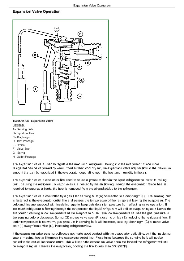
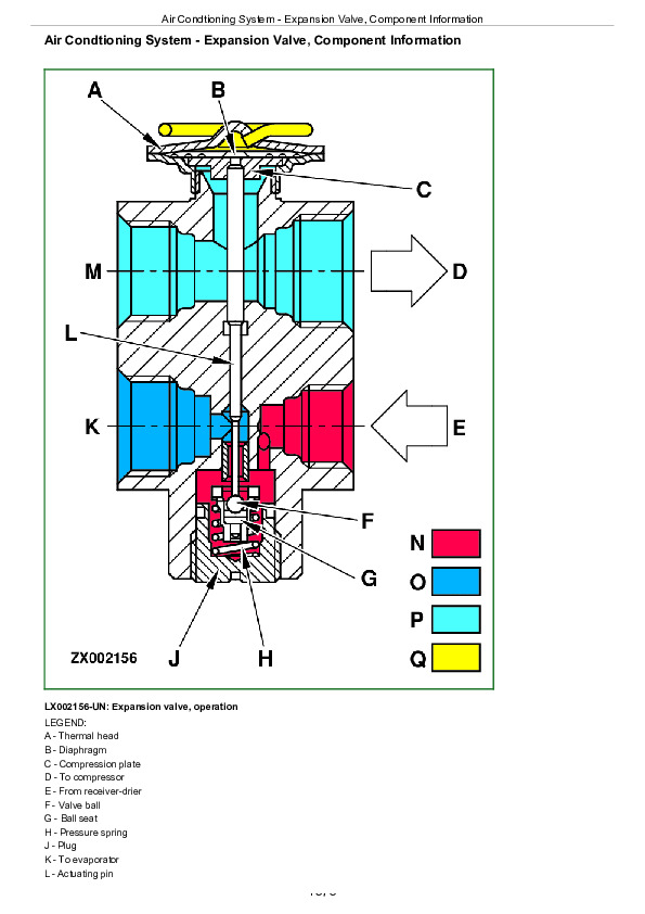
Air Condtioning System – Expansion Valve, Component Information….1576
Thermostat Switch….1578
Heating and Ventilation….1579
Section 299: Special Tools (Dealer-Fabricated)….1581
Group 05: Special Tools (Dealer-Fabricated)….1581
Special Tools (Dealer-Fabricated) — Summary….1583
Retainer Tool….1584
Adjustment Tool….1585
DFRW2—Needle Valve Test Hose Assembly….1586
DFLX10 and DFLX11—Test Harnesses….1587
DFLX12—Special Tool for 11-bit and 29-bit CAN BUS….1588
DFLX14—Solenoid Valve Test Harness….1589
Group 10: Special Tools (Available as Spare Parts)….1581
Special tool information….1591

John Deere 1654, 1854, 2054, 2104, 6165J, 6185J, 6205J, 6210J Tractors Diagnosis & Tests Service Manual (TM802219)


INSTANT DOWNLOAD


Posted on

John Deere 4WD Loaders 544E, 544E LL, 544E TC, 624E, 644E Repair Service Manual (TM1414)


INSTANT DOWNLOAD


Complete service repair manual for John Deere 4WD Loaders 544E, 544E LL, 544E TC, 624E, 644E, with workshop information to maintain, diagnostic, repair, service like professional mechanics.

John Deere 4WD Loaders 544E, 544E LL, 544E TC, 624E, 644E workshop service repair manual includes:
* Numbered table of contents easy to use so that you can find the information you need fast.
* Detailed sub-steps expand on repair procedure information
* Numbered instructions guide you through every repair procedure step by step.
* Notes, cautions and warnings throughout each chapter pinpoint critical information.
* Bold figure number help you quickly match illustrations with instructions.
* Detailed illustrations, drawings and photos guide you through every procedure.
* Enlarged inset helps you identify and examine parts in detail.

TM1414 – John Deere 544E, 544E LL, 544E TC, 624E and 644E 4WD Loader Technical Manual (Repair).PDF

Total Pages: 782 pages
File Format: PDF (bookmarked, ToC, Searchable, Printable)
Language: English

ctm138519 English – TeamMate™ II 1200 Series Inboard Planetary Axles -: (Worldwide Edition) CTM
ctm4 English – Series 300 – 3179,4239,6359,4276,6414 Diesel Engines CTM
ctm6 English – Series 400, 6076 Diesel Engines ( – 499999) CTM
ctm8 English – Series 300 3029 (S.N. -499999), 4039, 4045, 6059 and 6068 Diesel Engines CTM

omt131709 English – OPERATORS MANUAL 544E, 544E LL, AND 544E TC LOADERS 624E LOADER 644E LOADER Operator’s Manual.pdf

MAIN SECTIONS
Foreword
General Information
Safety Information
General Specifications
Torque Values
Fuels And Lubricants
Wheels
Powered Wheels And Fastenings
Axles And Suspension Systems
Removal And Installation
Axle Shafts, Bearings And U-Joints
Hydraulic System
Transmission
Removal And Installation
Controls Linkage
Input Drive Shafts And U-Joints
Gear, Shafts, Bearings And Power Shift Clutch
Hydraulic System
Engine
Removal And Installation
Engine Auxiliary Systems
Cold Weather Starting Aids
Cooling System
Speed Controls
Intake System
External Fuel Supply System
Dampener Drive
Elements
Steering System
Secondary Steering
Hydraulic System
Service Brakes
Active Elements
Hydraulic System
Park Brake
Active Elements
Controls Linkage
Equipment Attaching
Drawbar
Electrical Systems
Batteries, Support And Cables
Alternator, Regulator And Charging System Wiring
Lighting System
Wiring Harness And Switches
Motors And Actuators
Frame Or Supporting Structure
Frame Installation
Frame Bottom Guards
Chassis Weights
Operator`s Station
Removal And Installation
Operator Enclosure
Seat And Seat Belt
Heating And Air Conditioning
Loader
Bucket
Frames
Hydraulic System
Dealer Fabricated Tools

TABLE OF CONTENTS
Section I: General Information…17
Group I: Safety Information…17
Handle Fluids Safely-Avoid Fires…20
Prevent Battery Explosions…21
Prepare for Emergencies…22
Prevent Acid Burns…23
Handle Chemical Products Safely…25
Avoid High-Pressure Fluids…26
Park Machine Safely…27
Support Machine Properly…28
Wear Protective Clothing…29
Work in Clean Area…30
Service Machines Safely…31
Work In Ventilated Area…32
Illuminate Work Area Safely…33
Replace Safety Signs…34
Use Proper Lifting Equipment…35
Remove Paint Before Welding or Heating…36
Avoid Heating Near Pressurized Fluid Lines…37
Keep ROPS Installed Properly…38
Service Tires Safely…39
Avoid Harmful Asbestos Dust…40
Practice Safe Maintenance…41
Use Proper Tools…42
Dispose of Waste Properly…43
Live With Safety…44
Group II: General Specifications…649
544E Specifications…649
544E Drain And Refill Capacities…53
544E LL Specifications…649
544E LL Drain And Refill Capacities…58
544E TC Specifications…649
544E TC Drain And Refill Capacities…63
624E Specifications…649
624E Drain And Refill Capacities…68
644E Specifications…649
644E Drain And Refill Capacities…73
Group III: Torque Values…18
Hardware Torque Specifications…649
ROPS Torque Specifications…649
Metric Bolt and Cap Screw Torque Values…77
Additional Metric Cap Screw Torque Values…78
Unified Inch Bolt and Cap Screw Torque Values…80
Check Oil Lines And Fittings…81
Service Recommendations for O-Ring Boss Fittings…82
Service Recommendations for Flat Face O-Ring Seal Fittings…84
Service Recommendations for Metric Series Four Bolt Flange Fitting…86
Service Recommendations For Inch Series Four Bolt Flange Fittings…88
Group IV: Fuels And Lubricants…18
Fuel Specifications…649
Storing Fuel…92
Fuel Tank…93
Engine Oil…94
Transmission Oil…95
Hydraulic System Oil…96
Differential Oil…97
Grease…98
Alternative and Synthetic Lubricants…99
Lubricant Storage…100
Engine Coolant…101
Section 01: Wheels…102
Group 0110: Powered Wheels And Fastenings…102
Other Material…648
Specifications…649
Remove Tire…106
Install Tire…108
544E And 544E TC…110
544E LL…111
624E…112
644E…113
Section 02: Axles And Suspension Systems…114
Group 0200: Removal And Installation…114
John Deere 1200 And 1400 Series Axles-Use CTM18…417
Other Material…648
Specifications…649
Remove And Install Front Axle And Differential…119
Remove Rear Axle And Differential…122
Install Rear Axle And Differential Assembly…124
Group 0225: Axle Shafts, Bearings And U-Joints…114
Other Material…648
Specifications…649
Disassemble, Inspect, And Assemble Double Universal Joint, Support Bearing And Universal Joint Drive Shaft…130
Remove, Disassemble, Assemble And Install Rear Differential Drive Line…132
Group 0260: Hydraulic System…114
Remove, Disassemble, Assemble And Install Differential Lock Solenoid Valve…135
Section 03: Transmission…137
Group 0300: Removal And Installation…137
Essential Tools…225
Service Equipment And Tools…647
Specifications…649
Remove And Install Transmission…143
Group 0315: Controls Linkage…137
Other Material…648
Specifications…649
Disassemble And Assemble Transmission Control Linkage…152
Transmission Direction Selector Linkage Adjustment…155
Transmission Speed Selector Linkage Adjustment…156
Group 0325: Input Drive Shafts And U-Joints…137
Specifications…649
Remove, Disassemble, Assemble And Install Transmission Drive Shaft…159
Group 0350: Gear, Shafts, Bearings And Power Shift Clutch…137
Essential Tools…225
Service Equipment And Tools…647
Other Material…648
Specifications…649
Install Repair Stand…166
Remove And Install Torque Converter…167
Remove Clutch Packs…191
Remove And Install Forward And First Drive Gears…175
Remove And Install Reverse And Second Drive Gears…177
Remove And Install Third And Fourth Drive Gears…179
Disassemble And Assemble Clutch Packs…191
Clutch Packs…191
Remove And Install Fourth Gear Idler Gear-544E, 544E LL, 544E TC…192
Remove And Install Fourth Gear Idler Gear-624E, 644E…194
Fourth Gear Idler Orifice Sizes…196
Install Third And Fourth Gear Clutch Pack, Adjust End Play…197
Install Second And Reverse, First And Forward Gear Clutch Packs…202
Remove And Install Output Flange And Park Brake…210
Remove And Install Output Shaft And Seals…214
Remove And Install Output Gear And Oil Shields…221
Group 0360: Hydraulic System…138
Essential Tools…225
Service Equipment And Tools…647
Other Material…648
Specifications…649
Remove Oil Supply Flange And Oil Pump…229
Disassemble Oil Supply Flange…232
Assemble Oil Supply Flange…234
Input Drive Shaft Orifice Sizes…236
Disassemble Oil Pump…237
Assemble Oil Pump…238
Install Oil Pump On Oil Supply Flange…240
Install Oil Supply Flange And Oil Pump…243
Remove And Install Converter Minimum Pressure Regulator…247
Remove And Install Transmission Oil Filter…248
Remove And Install Suction Oil Strainer…249
Remove Transmission Control Valve…250
Disassemble Transmission Control Valve…252
Disassemble And Assemble Cover Plate…253
Disassemble And Assemble Pressure Regulating Valve, Pilot Valve, And Modulation Piston…255
Disassemble And Assemble Direction Selector Valve…257
Disassemble And Assemble Clutch Cut-Off Valve And Clutch Cut-Off Pilot Orifice…259
Disassemble And Assemble Speed Selector Valve…261
Assemble Transmission Control Valve…263
Install Transmission Control Valve…264
Remove And Install Main Hydraulic Filter…266
Cross Section Of Thermal Bypass Valve…267
Remove, Disassemble, Assemble And Install Thermal Bypass Valve…268
Section 04: Engine…270
Group 0400: Removal And Installation…270
John Deere 6076 Engine Repair-Use CTM6…272
John Deere 6059 And 6068 Engine Repair-Use CTM8…273
John Deere 6359 And 6414 Engine Repair-Use CTM4…274
Special Or Essential Tools…566
Service Equipment And Tools…647
Other Material…648
Specifications…649
Disconnect Turbocharger Oil Inlet Line…282
Remove And Install Engine…283
Remove And Install Oil Pan…286
Remove And Install Fuel Injection Pump-544E, 624E (DB2-Non-Retained Shaft)…287
Remove And Install DB2 Fuel Injection Pump Drive Shaft-544E, 624E…289
Remove Fuel Injection Pump-544E, 624E (DB4-Retained Shaft)…292
Install Fuel Injection Pump-544E, 624E (DB4-Retained Shaft)…295
Remove Fuel Injection Pump-644E…298
Install Fuel Injection Pump-644E…300
Remove And Install Fuel Filter Check Valve-644E…303
Remove And Install Fuel Injection Nozzle-544E, 624E…304
Remove Fuel Injection Nozzle-644E…306
Inspect And Clean Cylinder Head Nozzle Bore-644E…307
Inspect And Clean Nozzle Seating Surface-644E…308
Install Fuel Injection Nozzle-644E…309
Bleed Fuel System-544E, 624E…312
Bleed Fuel System-644E…314
Remove And Install Turbocharger…315
Remove And Install Water Pump-544E, 624E…317
Remove And Install Water Pump-644E…318
Remove And Install Fan Drive-644E…320
Section 05: Engine Auxiliary Systems…321
Group 0505: Cold Weather Starting Aids…321
Specifications…649
Remove And Install Starting Aid Solenoid And Nozzle…324
Remove And Install Engine Coolant Heater…326
Group 0510: Cooling System…321
Specifications…649
Remove And Install Compressor Belt (If Equipped) And Fan Belts…330
Remove And Install Fan…331
Remove And Install Radiator…332
Remove And Install Oil Cooler…334
Group 0515: Speed Controls…321
Other Material…648
Specifications…649
Remove And Install Speed Control Linkage…339
Engine Speed Control Linkage Adjustment…340
Fuel Shut-Off Cable Adjustment-644E…342
Group 0520: Intake System…321
Specifications…649
Remove And Install Air Filter Elements-544E, 624E…345
Tighten Air Cleaner Hose Clamps…347
Remove And Install Air Filter Elements-644E…348
Test Air Intake System For Leaks…350
Group 0560: External Fuel Supply System…321
Other Material…648
Specifications…649
Remove And Install Fuel Tank-544E, 624E And 644E (Serial No. 537537-)…354
Remove And Install Fuel Tank-644E (Serial No. -537536)…356
Remove And Install Water Separator…358
Disassemble And Assemble Water Separator…359
Section 07: Dampener Drive…360
Group 0752: Elements…360
Specifications…649
Remove And Install Dampener…363
Section 09: Steering System…364
Group 0930: Secondary Steering…364
Remove And Install Secondary Steering Pump, Motor, And Relay…366
Remove And Install Secondary Steering Inlet Manifold…367
Disassemble And Assemble Secondary Steering Inlet Manifold…368
Group 0960: Hydraulic System…364
Special Or Essential Tools…566
Service Equipment And Tools…647
Other Material…648
Specifications…649
Remove And Install Steering Valve…374
Disassemble Steering Valve…376
Cross Section Of Steering Valve…379
Assemble Steering Valve…380
Remove, Disassemble, Assemble And Install Steering Column…384
Remove And Install Steering Cylinders…386
Disassemble Steering Cylinder…388
Cross Section Of Steering Cylinder…392
Assemble Steering Cylinder…393
Remove And Install Steering Cylinder Bushings…399
Remove And Install Priority Valve…400
Cross Section Of Priority Valve…401
Disassemble And Assemble Priority Valve…402
Remove And Install Crossover Relief Valve…404
Cross Section Of Crossover Relief Valve…406
Disassemble And Assemble Crossover Relief Valve…407
Remove And Install Steering Accumulator-644E Later Machines…409
Disassemble And Assemble Steering Accumulator-644E Later Machines…411
Charge Steering Accumulator-644E Later Machines…413
Section 10: Service Brakes…415
Group 1011: Active Elements…415
John Deere 1200 And 1400 Series Axles-Use CTM18…417
Specifications…649
Inspect Brakes…419
Remove And Install Brake Assembly…420
Inspect Brake Elements…421
Group 1060: Hydraulic System…415
Service Equipment And Tools…647
Specifications…649
Remove And Install Brake Valve…425
Brake Valve Identification…427
Disassemble And Assemble Brake Valve…428
Remove And Install Brake Pump…430
Disassemble Brake Pump…432
Inspect Brake Pump Parts…434
Assemble Brake Pump…435
Disassemble And Assemble Compensator Valve…437
Remove And Install Brake Accumulators…439
Disassemble And Assemble Brake Accumulators…441
Charge Brake Accumulator…443
Hydraulic Brake Bleeding Procedure…445
Section 11: Park Brake…447
Group 1111: Active Elements…447
Specifications…649
Other Material…648
Remove And Install Park Brake…451
Disassemble And Assemble Park Brake…452
Group 1115: Controls Linkage…447
Remove And Install Park Brake Linkage…454
Adjust Park Brake Linkage…455
Section 15: Equipment Attaching…456
Group 1511: Drawbar…456
Specifications…649
Install Counterweight/Drawbar…459
Section 16: Electrical Systems…460
Group 1671: Batteries, Support And Cables…460
Specifications…649
Handle Batteries Safely…464
Test Batteries Using Coolant And Battery Tester…465
Test Batteries Using High Rate Discharge Test…466
Charge Battery…467
Remove And Install Batteries…468
Group 1672: Alternator, Regulator And Charging System Wiring…460
Alternator Repair-Use CTM77…470
Service Equipment And Tools…647
Specifications…649
Remove And Install Alternator (Except BOSCH)…473
Remove And Install BOSCH Alternator…475
Group 1673: Lighting System…460
Specifications…649
Replace Halogen Bulbs…478
Remove And Install Lights…480
Group 1674: Wiring Harness And Switches…460
Special Or Essential Tools…566
Specifications…649
Clutch Cut-Off Switch Adjustment…484
Remove And Install Brake Low Pressure Switch…485
Return-To-Dig Adjustment…487
Boom Height Kickout Adjustment…488
Replace DEUTSCH DEUTSCH is a trademark of the Deutsch Company. Connectors…460
Install DEUTSCH DEUTSCH is a trademark of the Deutsch Company. Contact…460
Replace WEATHER PACK Weather Pack is a trademark of Packard Electric. Connector…460
Install WEATHER PACK Weather Pack is a trademark of Packard Electric. Contact…460
Remove Connector Body From Blade Terminals…498
Remove Blade Terminals From Fuse Block…499
Group 1677: Motors And Actuators…461
Starting Motor Repair-Use CTM77…501
Special Or Essential Tools…566
Specifications…649
Remove And Install Starting Motor…504
Section 17: Frame Or Supporting Structure…505
Group 1740: Frame Installation…505
Service Equipment And Tools…647
Other Material…648
Specifications…649
Welding Repair Of Major Structure…510
Separate Engine And Loader Frame…512
Remove And Install Upper Pivot Bearing And Seals…515
Remove And Install Lower Pivot Bushing And Seals…517
Group 1746: Frame Bottom Guards…505
Remove And Install Fuel Tank Bottom Guard…519
Repair Bottom Guards…520
Remove And Install Auxiliary Bottom Guards (If Equipped)…521
Group 1749: Chassis Weights…505
Specifications…649
Remove And Install Counterweights…525
Section 18: Operator's Station…527
Group 1800: Removal And Installation…527
Special Or Essential Tools…566
Service Equipments And Tools…531
Other Material…648
Specifications…649
Remove And Install Cab Or Canopy…534
Tilt Cab Or Canopy…540
Group 1810: Operator Enclosure…527
Special Or Essential Tools…566
Other Material…648
Specifications…649
Remove And Install Windowpane And Molding…546
Remove And Install Windshield Washer…548
Remove, Disassemble, Assemble And Install Front Windshield Wiper…549
Remove, Disassemble, Assemble And Install Rear Windshield Wiper…550
Adjust Front Windshield Wiper…551
Remove And Install Defroster Fan…552
Remove And Install Door Handle And Door/Window Release…553
Group 1821: Seat And Seat Belt…527
Specifications…649
Disassemble And Assemble Seat…557
Group 1830: Heating And Air Conditioning…527
Special Or Essential Tools…566
Service Equipment And Tools…647
Other Material…648
Service Parts Kits For Compressor…572
Specifications…649
Proper Refrigerant Handling…574
Refrigerant (R-12) Cautions…575
Air Conditioning Gauge Set Installation Procedure…576
Refrigerant Recovery…578
Evacuate R12 System…580
Charge R12 System…583
Check And Add Compressor Oil…585
Remove And Install Compressor And High Pressure Switch…587
Volumetric Efficiency Test-R12…588
Make Shaft Seal Leak Test…590
Disassemble And Inspect Compressor…592
Clutch Pulley, Bearing And Hub Inspection…598
Replacing Clutch Pulley Bearing…599
Replace Shaft Seal Seat…601
Assemble Compressor…602
Remove And Install Condenser…605
Remove And Install Evaporator And Expansion Valve…607
Expansion Valve Bench Test And Adjustment…609
Remove And Install Receiver/Dryer And Low Pressure Switch…611
Remove And Install Condenser Fan Motors…613
Remove And Install Blower Wiring Harness…614
Thermostat Switch Bench Test…615
Disassemble And Assemble Blower Motor…617
Remove And Install Heater Core…618
Remove And Install Cab Heater Hoses And Controls…619
Section 31: Loader…620
Group 3102: Bucket…620
Other Material…648
Specifications…649
Remove And Install Bucket Tooth Shanks And Tips…625
Remove And Install Bucket…627
Replace Welded Bucket Cutting Edges…628
Remove And Install Cutting Edges (For Bucket With Wear Plates)…629
Repair Cracked Cutting Edge…630
Group 3140: Frames…620
Service Equipment And Tools…647
Other Material…648
Specifications…649
Remove And Install Bucket Tilt Linkage-544E, 624E, And 644E…635
Remove And Install Bucket Linkage Seals And Bushings-544E, 624E, And 644E…637
Disassemble And Assemble Bucket Tilt Linkage-544E TC And 544E LL…639
Disassemble And Assemble Tool Carrier-544E TC…641
Remove And Install Boom Bushings And Shims-544E, 624E, And 644E…642
Remove And Install Boom Bushings And Shims-544E TC And 544E LL…644
Group 3160: Hydraulic System…620
Service Equipment And Tools…647
Other Material…648
Specifications…649
Remove And Install Main Hydraulic Pump…652
Disassemble, Inspect And Assemble Main Hydraulic Pump…653
Remove And Install Loader Control Valve…656
Disassemble And Assemble Loader Control Valve-(Serial No. -534614)…658
Disassemble And Assemble Loader Control Valve-(Serial No. 534615-)…659
Service Bucket And Boom Section Pilot Orifice Check Valve-Later Machines Only…660
Disassemble And Assemble Boom Valve Section-All Machines; And Bucket Valve Section-544E TC And 544E LL…661
Disassemble And Assemble Auxiliary Valve Section-All Machines; And Bucket Section-544E, 624E, And 644E…665
Disassemble And Assemble System Relief Valve…668
Disassemble And Assemble Shim Adjustable Circuit Relief Valve…670
Disassemble And Assemble Anti-Cavitation Valve…672
Disassemble And Assemble Screw Adjustable Circuit Relief Valve…674
Remove And Install Boom Cylinder…676
Remove And Install Bucket Cylinder…678
Cross Section Of Boom Or Bucket Cylinder…680
Disassemble Boom Or Bucket Cylinder…682
Assemble Boom Or Bucket Cylinder…684
Remove And Install Bucket Or Boom Cylinder Bushings And Seals…690
Remove, Disassemble, Assemble And Install Boom Solenoid Valve…691
Remove And Install Hydraulic Reservoir…693
Hydraulic Oil Clean-Up Procedure Using Portable Filter Caddy…745
Remove And Install Pilot Control Valves (Two Lever Controller)…699
Disassemble And Assemble Pilot Control Valve (Two-Lever Controller)…701
Remove And Install Pilot Controller (Single Lever Controller)…707
Cross Section Of Single Lever Pilot Controller (Serial No. -537112)…709
Disassemble Single Lever Pilot Controller (Serial No. -537112)…711
Assemble Single Lever Pilot Controller (Serial No. -537112)…716
Disassemble Single Lever Pilot Controller (Serial No. 537113-)…722
Assemble Single Lever Controller (Serial No. 537113-)…727
Remove, Disassemble, Assemble And Install Pressure Reducing Valve…733
Remove And Install Pin Disconnect Cylinders-544E TC…735
Cross Section Of Pin Disconnect Cylinder-544E TC…736
Disassemble Pin Disconnect Cylinder-544E TC…737
Assemble Pin Disconnect Cylinder-544E TC…740
Disassamble And Assemble Pin Disconnect Solenoid Valve-544E TC…743
Hydraulic Oil Clean-Up Procedure Using Portable Filter Caddy…745
Section 99: Dealer Fabricated Tools…748
Group 9900: Dealer Fabricated Tools…748
DF1055 And JD38002 Yoke Holding Tool…750
DF1056 Input Pinion Shaft Adjusting Tool…751
DF1057 Axle Adjusting Tool…752
DF1025 Oil Supply Flange Back-Off Brackets…753
DF1026 Pre-Load Clutch Pack Compression Ring Assembly Jig…754
DF1027 Stand Mounting Bracket…755
DFT1071 Cab Tilt Pivots And Hinges…757
JDG588 Shaft Alignment Tool…759
DF1044 Air Deflector Bushing…760

John Deere 4WD Loaders 544E, 544E LL, 544E TC, 624E, 644E Repair Service Manual (TM1414)


INSTANT DOWNLOAD


Posted on

John Deere 4WD Loaders 544E, 544E LL, 544E TC, 624E, 644E Operation & Test Service Manual (TM1413)


INSTANT DOWNLOAD


Complete Diagnosis and Test manual with Electrical Wiring Diagrams for John Deere 4WD Loaders 544E, 544E LL, 544E TC, 624E, 644E, with all the shop information to maintain, diagnose, test, and service like professional mechanics.

John Deere 4WD Loaders 544E, 544E LL, 544E TC, 624E, 644E workshop Diagnostics and Test manual includes:
* Numbered table of contents easy to use so that you can find the information you need fast.
* Detailed sub-steps expand on repair procedure information
* Numbered instructions guide you through every repair procedure step by step.
* Troubleshooting and electrical service procedures are combined with detailed wiring diagrams for ease of use.
* Notes, cautions and warnings throughout each chapter pinpoint critical information.
* Bold figure number help you quickly match illustrations with instructions.
* Detailed illustrations, drawings and photos guide you through every procedure.
* Enlarged inset helps you identify and examine parts in detail.

TM1413 – John Deere 544E, 544E LL, 544E TC, 624E and 644E 4WD Loader Technical Manual (Operation and Test ).PDF

Total Pages: 1,120 pages
File Format: PDF (bookmarked, ToC, Searchable, Printable)
Language: English

ctm138519 English – TeamMate™ II 1200 Series Inboard Planetary Axles -: (Worldwide Edition) CTM
ctm4 English – Series 300 – 3179,4239,6359,4276,6414 Diesel Engines CTM
ctm6 English – Series 400, 6076 Diesel Engines ( – 499999) CTM
ctm8 English – Series 300 3029 (S.N. -499999), 4039, 4045, 6059 and 6068 Diesel Engines CTM
omt131709 English – OPERATORS MANUAL 544E, 544E LL, AND 544E TC LOADERS 624E LOADER 644E LOADER Operator’s Manual

MAIN SECTIONS
Foreword
General Information
Safety Information
General Specifications
Torque Values
Fuels And Lubricants
Wheels
Powered Wheels And Fastenings
Axles And Suspension Systems
Removal And Installation
Axle Shafts, Bearings And U-Joints
Hydraulic System
Transmission
Removal And Installation
Controls Linkage
Input Drive Shafts And U-Joints
Gear, Shafts, Bearings And Power Shift Clutch
Hydraulic System
Engine
Removal And Installation
Engine Auxiliary Systems
Cold Weather Starting Aids
Cooling System
Speed Controls
Intake System
External Fuel Supply System
Dampener Drive
Elements
Steering System
Secondary Steering
Hydraulic System
Service Brakes
Active Elements
Hydraulic System
Park Brake
Active Elements
Controls Linkage
Equipment Attaching
Drawbar
Electrical Systems
Batteries, Support And Cables
Alternator, Regulator And Charging System Wiring
Lighting System
Wiring Harness And Switches
Motors And Actuators
Frame Or Supporting Structure
Frame Installation
Frame Bottom Guards
Chassis Weights
Operator`s Station
Removal And Installation
Operator Enclosure
Seat And Seat Belt
Heating And Air Conditioning
Loader
Bucket
Frames
Hydraulic System

TABLE OF CONTENTS
Section 9000: General Information…16
Group 01: Safety Information…16
Handle Fluids Safely-Avoid Fires…19
Prevent Battery Explosions…20
Prepare for Emergencies…21
Prevent Acid Burns…22
Handle Chemical Products Safely…24
Avoid High-Pressure Fluids…25
Park Machine Safely…26
Support Machine Properly…27
Wear Protective Clothing…28
Work in Clean Area…29
Service Machines Safely…30
Work In Ventilated Area…31
Illuminate Work Area Safely…32
Replace Safety Signs…33
Use Proper Lifting Equipment…34
Remove Paint Before Welding or Heating…35
Avoid Heating Near Pressurized Fluid Lines…36
Keep ROPS Installed Properly…37
Service Tires Safely…38
Avoid Harmful Asbestos Dust…39
Practice Safe Maintenance…40
Use Proper Tools…41
Dispose of Waste Properly…42
Live With Safety…43
Group 02: General Specifications…16
544E Specifications…48
544E Drain And Refill Capacities…52
544E LL Specifications…53
544E LL Drain And Refill Capacities…57
544E TC Specifications…58
544E TC Drain And Refill Capacities…62
624E Specifications…63
624E Drain And Refill Capacities…67
644E Specifications…68
644E Drain And Refill Capacities…72
Group 03: Torque Values…17
Hardware Torque Specifications…74
ROPS Torque Specifications…75
Metric Bolt and Cap Screw Torque Values…76
Additional Metric Cap Screw Torque Values…77
Unified Inch Bolt and Cap Screw Torque Values…79
Check Oil Lines And Fittings…80
Service Recommendations for O-Ring Boss Fittings…81
Service Recommendations for Flat Face O-Ring Seal Fittings…83
Service Recommendations for Metric Series Four Bolt Flange Fitting…85
Service Recommendations For Inch Series Four Bolt Flange Fittings…87
Group 04: Fuels And Lubricants…17
Fuel Specifications…90
Storing Fuel…91
Fuel Tank…92
Engine Oil…93
Transmission Oil…94
Hydraulic System Oil…95
Differential Oil…96
Grease…97
Alternative and Synthetic Lubricants…99
Synthetic Lubricants…99
Lubricant Storage…100
Cold Weather Operation…101
Engine Coolant…102
Section 9005: Operational Checkout Procedure…103
Group 10: Operational Checkout Procedure…103
Operational Checkout Record Sheet-544E, 624E, And 644E…108
Complete Machine Operational Checkout…112
Section 9010: Engine Operation And Tests…166
Group 05: Theory Of Operation…166
Cooling System Operation-544E, 624E…169
Cooling System Operation-644E…170
Thermostat Operation…171
Air Cleaner Operation…172
Turbocharger Operation…174
Engine Lubrication-544E, 624E…176
Engine Lubrication Operation-644E…178
Fuel System Operation-544E, 624E…180
Fuel System Operation-644E…181
Fuel Supply Pump Operation-544E, 624E…182
Fuel Pump Operation-644E…183
Fuel Filter Operation…185
Fuel Injection Pump Operation-544E, 624E…186
Fuel Injection Pump Operation-644E…188
Fuel Injection Nozzle Operation-544E, 624E…189
Fuel Injection Nozzle Operation-644E…190
Group 10: System Operational Checks…166
Engine Operational Checks…208
Group 15: Diagnostic Information…166
Diagnose Engine Malfunctions…236
Coolant Requirements…248
Group 20: Adjustments…166
JT05801 Clamp-On Electronic Tachometer Installation…824
JT05800 Digital Thermometer Installation…825
D01084AA Tachometer Reader Installation Procedure…254
Valve Clearance Adjustment-544E, 624E…255
Valve Clearance Adjustment-644E…257
Fan Belt Tension Adjustment…259
Injection Pump Static Timing Adjustment-544E, 624E…261
Injection Pump Static Timing Adjustment-644E…263
Slow And Fast Idle Adjustment-544E, 624E…265
Slow Idle Adjustment-644E…267
Fast Idle Adjustment-644E…269
Speed Control Linkage Adjustment…270
Fuel Shut-Off Cable Adjustment-644E…272
Bleed The Fuel System-544E, 624E…273
Bleed The Fuel System-644E…274
Group 25: Tests…167
JT05801 Clamp-On Electronic Tachometer Installation…824
JT05800 Digital Thermometer Installation…825
Dampener Runout Check…278
Valve Lift Check…279
Compression Pressure Test-544E, 624E…280
Compression Pressure Test-644E…282
Engine Oil Pressure Test-544E, 624E…284
Engine Oil Pressure Test-644E…285
Turbocharger Shaft Axial End Play Test…287
Turbocharger Shaft Radial Movement Test…288
Cooling System Test…289
Fuel Pump Pressure Test-544E, 624E…291
Fuel Pump Pressure Test-644E…292
Air Filter Restriction Indicator Switch Test…294
Radiator Air Flow Test…296
JT05529 Airflow Meter Test Record…298
Engine Power Test Using Engine Pulldown…300
Engine Power Test Using Turbocharger Boost Pressure…302
Air Intake System Leakage Test…304
Fuel Line Leakage Test…306
Section 9015: Electrical System Operation And Test…307
Group 00: Electrical System Operation And Test…307
Safety Precautions…314
Using Booster Batteries-12 Volt System…317
Visually Inspect Electrical System…320
Testing The Electrical System…321
Common Circuit Test…322
Electrical Operational Checks…323
Electrical Schematic Symbols…324
Wiring Diagram Information…325
Battery-Diagnose Malfunctions…327
Battery Operation…328
Battery Specifications…330
Fuse Specifications…331
Bulb Replacement Specifications…332
Diagnose Power And Ground Circuit Malfunctions…333
Power Circuit Operation…336
Power Circuit Wiring Diagram…338
Power Circuit Test…339
Diagnose Starter Circuit Malfunctions…344
Diagnose Fuel Shut-Off Malfunctions-544E, 624E…347
Starting Circuit And Fuel Shut-Off Solenoid Operational Checks…348
Starting Circuit And Fuel Shut-Off Solenoid Operation…354
Starter Operation…356
Start Circuit And Fuel Shut-Off Solenoid Wiring Diagram…359
Start Circuit And Fuel Shut-Off Solenoid Tests…360
Diagnose Charging Circuit Malfunctions-65 Amp Alternator…361
Alternator Operation-65 Amp Motorola…365
Charging Circuit Operation-65 Amp Motorola Alternator-(Serial No. -532819)…367
Charging Circuit Wiring Diagram-65 Amp Motorola-(S.N. -532819)…368
Charging Circuit Operation-65 Amp Motorola Alternator-(Serial No. 532820-)…369
Charging Circuit Wiring Diagram-65 Amp Motorola-(S.N. 532820-)…370
Diagnose Charging Circuit Malfunctions-90 Amp And 105 Amp Alternator…371
Alternator Operation-90 Amp And 105 Amp Delco Remy…374
Charging Circuit Operation-105 Amp Delco-Remy Alternator-(S.N. 518774-)…376
Charging Circuit Wiring Diagram-105 Amp Alternator-(S.N. 518774-)…377
Charging Circuit Operation-90 Amp Delco-Remy Alternator…378
Charging Circuit Wiring Diagram-90 Amp Delco-Remy Alternator…379
Diagnose Charging Circuit Malfunctions-130 Amp Alternator…380
Alternator Operation-130 Amp Motorola…388
Charging Circuit Operation-130 Amp Motorola Alternator…389
Charging Circuit Wiring Diagram-130 Amp Motorola Alternator…390
130 Amp Alternator Voltage Adjustment…391
Diagnose Logic Module And Warning Alarm Circuit Malfunctions…392
Logic Module And Warning Alarm Circuit Operation…393
Logic Module And Warning Alarm Wiring Diagram…395
Logic Module Test In Machine…396
Logic Module Bench Test…399
Diagnose Indicator Circuit Malfunctions-Top Row…401
Indicator Circuits Operation-Top Row…409
Indicator Circuits Wiring Diagram-Top Row…410
Diagnose Indicator Circuit Malfunctions-Middle Row…411
Indicator Circuits Operation-Middle Row…419
Indicator Circuits Wiring Diagram (Middle Row)…421
Park Brake Switch Adjustment…422
Pressure Switch And Sender Test…423
Diagnose Gauges And Horn Circuit Malfunctions…424
Gauges And Horn Circuits Operation…430
Gauges And Horn Circuit Wiring Diagram…431
Diagnose Return-To-Dig And Boom Height Kickout Malfunctions…432
Return-To-Dig And Boom Height Kickout Circuit Operation…437
Return-To-Dig And Boom Height Kickout Wiring Diagram…439
Boom Height Kickout Adjustment…818
Return-To-Dig Adjustment…820
Diagnose Start Aid, Reverse Warning Alarm, And Cigar Lighter Circuit Malfunctions…444
Start Aid, Reverse Warning Alarm, And Cigar Lighter Circuit Operation…448
Start Aid, Reverse Warning Alarm, And Cigar Lighter Circuit Operation Wiring Diagram…449
Diagnose Secondary Steering System Malfunctions…450
Secondary Steering Circuit Operation…456
Secondary Steering Wiring Diagram…458
Secondary Steering Circuit Test…459
Secondary Steering Controller Test…460
Secondary Steering Pressure Switch…461
Diagnose Hour Meter Circuit Malfunctions…462
Hour Meter Circuit Operation…468
Hour Meter Circuit Wiring Diagram…470
Diagnose Boom Down Circuit Malfunctions…471
Boom Down Circuit Operation-(Serial No. -518527)…476
Boom Down Circuit Wiring Diagram-(Serial No. -518527)…477
Boom Down Circuit Operation-(Serial No. 518528-521102)…478
Boom Down Circuit Wiring Diagram-(Serial No. 518528-521102)…479
Boom Down Circuit Operation-(Serial No. 521103-)…480
Boom Down Circuit Wiring Diagram-(Serial No. 521103-)…481
Diagnose Differential Lock And Clutch Cut-Off Circuit Malfunctions…482
Differential Lock And Clutch Cut-Off Circuit Operation…487
Differential Lock And Clutch Cut-Off Circuits Wiring Diagram…488
Diagnose Turn Signal And Flasher Circuit Malfunctions…489
Turn Signal And Flasher Indicator Circuit Operation…493
Turn Signal And Flasher Indicator Circuit Wiring Diagram…494
Diagnose Drive, Work, Brake And Gauge Light Circuit Malfunctions…495
Drive, Work, Brake And Gauge Light Circuit Operation…501
Drive, Work, Brake And Gauge Light Circuits Wiring Diagram…503
Diagnose Windshield Wiper And Washer Circuit Malfunctions…504
Windshield Wiper And Washer Circuit Operation…509
Windshield Wiper/Washer Circuit Wiring Diagram…510
Diagnose Pin Disconnect Circuit Malfunctions…511
Pin Disconnect Circuit Operation…513
Pin Disconnect Circuit Wiring Diagram…514
Radio Circuit Operation…515
Electrical Component Location Drawing…516
Section 9020: Power Train Operation And Tests…517
Group 05: Theory Of Operation…517
Power Train Component Overview…523
Drive Dampener…526
Transmission Clutch Engagement…527
Torque Converter Operation…528
Transmission Operation-Neutral…530
Transmission Operation-1st Gear Forward…532
Transmission Operation-2nd Gear Forward…534
Transmission Operation-3rd Gear Forward…536
Transmission Operation-4th Gear Forward…538
Transmission Operation-1st Gear Reverse…540
Transmission Operation-2nd Gear Reverse…542
Transmission Operation-3rd Gear Reverse…544
Clutch Operation…546
Transmission Hydraulic Components…548
Transmission Hydraulic System…550
Transmission Pump Operation…552
Transmission Control Valve Components…553
Transmission Control Valve-1st Gear Neutral…555
Transmission Control Valve-4th Gear Forward…557
Shift Modulation…559
Shift Modulation-1st Gear (Full Engagement)…561
Shift Modulation-1st Gear (Shift Initiated-Clutch Filling)…563
Shift Modulation-1st Gear (Modulation Starting)…565
Shift Modulation-2nd, 3rd, And 4th Gears…567
Thermal Bypass Valve Operation…569
Differential Lock Operation…570
Final Drive Operation…572
Axle Outer Seal And Bearing Operation…574
Axle Disconnect Operation…575
Brake Hydraulic System…576
Brake Pump Operation…578
Accumulator Operation…580
Brake Valve Operation…581
Wet Chambered Brake Valve…583
Pressure Reducing Valve Operation-Neutral…585
Pressure Reducing Valve Operation-Differential Lock On…587
Group 10: System Operational Checks…518
Power Train Operational Checks…601
Group 15: Diagnostic Information…518
Diagnose Transmission System Malfunctions…622
Diagnose Service Brake Malfunctions…631
Diagnose Differential/Axle Malfunctions…633
Diagnose Drive Line Malfunctions…636
Diagnose Park Brake Malfunctions…637
Hydraulic Circuit Symbols…807
Brake, Differential Lock Circuit Schematic…639
Power Train Schematic…640
Power Train And Brakes System Component Location…641
Group 20: Adjustments…518
Transmission Control Valve Linkage-FNR And Neutral Lock Adjustment…643
Transmission Control Valve Linkage-Speed Control Adjustment…644
Brake Pedal Adjusting Screw Adjustment (Early Units Only)…645
Front Axle Disconnect Adjustment…646
Clutch Cut-Off Switch Adjustment…647
Brake Pad Inspection…648
Hydraulic Brake Bleeding Procedure…650
Charge Brake Accumulator…652
Park Brake Linkage Adjustment…654
Park Brake Indicator Switch Adjustment…656
Brake Pump And Differential Lock System Oil Clean-Up Procedure Using Portable Filter Caddy…657
Group 25: Tests…518
JT05801 Clamp-On Electronic Tachometer Installation…824
JT05800 Digital Thermometer Installation…825
D01084AA Tachometer/Temperature Reader Installation Procedure…826
Transmission Oil Warm-Up Procedure…663
Brake, Differential Lock, And Hydraulic System Oil Warm-Up Procedure…664
Transmission Pump Flow Test…665
Transmission System Pressure, Element Leakage, And Shift Modulation Test…667
Lube Pressure Test…670
Converter Relief Pressure Test…672
Converter-In Pressure Test…674
Converter-Out Pressure Test…676
Converter-Out Flow Test…678
Transmission Oil Cooler Backflush Procedure…680
Transmission Oil Cooler Restriction Test…681
Clutch Cut-Off Valve Pressure Test…683
Pressure Reducing Valve Manifold Leakage Test…685
Transmission Oil Cooler Thermal Bypass Valve Test…687
Transmission Oil Cooler Bypass Valve Pressure Test…689
Torque Converter Stall Speed Test…691
Brake Pump Flow Test…692
Brake Pump Standby Pressure Test…694
Brake Valve Pressure Test…696
Brake Accumulator Precharge Test…698
Brake Valve Leakage Test…700
Brake Accumulator Inlet Check Valve Leakage Test…702
Differential Lock Pressure Test…704
Differential Lock Leakage Test…706
Axle Bearing Adjustment Check…708
No-Spin Differential Test…709
Section 9025: Hydraulic System Operation And Test…710
Group 05: Theory Of Operation…710
Steering Circuit Component Location…714
Steering Circuit Components…715
Steering Circuit Operation-Right Turn…717
Main Hydraulic Pump Operation…719
Priority Valve Operation…720
Steering Valve Operation…723
Crossover Relief Valve Operation…724
Steering Cylinder Operation…725
Steering Accumulator Operation-644E Later Units…726
Secondary Steering System Operation…727
Inlet Manifold Operation…728
Loader Hydraulic System…730
Pressure Reducing Valve-Secondary Boom Lower Operation…732
Pilot Controller Operation…734
Boom Section Operation…736
Bucket Section Orifice Check Valve…738
Bucket Section Operation-544E, 624E, And 644E…739
Bucket Section Operation-544E TC And 544E LL…741
Auxiliary Section Operation…743
System Relief Valve Operation…745
Circuit Relief Valve Operation…746
Anti-Cavitation Valve Operation…749
Loader Cylinder Design…750
Return Filter Operation…751
Pin Disconnect Circuit Operation-544E TC…752
Group 10: System Operational Checks…710
Hydraulic Operational Checks…770
Group 15: Diagnostic Information…710
Diagnose Hydraulic System Malfunctions…797
Hydraulic Circuit Symbols…807
Main Hydraulic System Component Location…808
Main Hydraulic System Schematic…809
Main Hydraulic System Schematic (Tandem Valve)…810
Hydraulic System Component Location-544E TC And 544E LL…811
Group 20: Adjustments…711
Hydraulic Oil Clean-Up Procedure Using Portable Filter Caddy…815
Boom Height Kickout Adjustment…818
Return-To-Dig Adjustment…820
Charge Steering Accumulator-644E Later Machines…821
Group 25: Tests…711
JT05801 Clamp-On Electronic Tachometer Installation…824
JT05800 Digital Thermometer Installation…825
D01084AA Tachometer/Temperature Reader Installation Procedure…826
Hydraulic Oil Warm-Up Procedure…828
Main Hydraulic Pump Flow Test…829
Loader System And Circuit Relief Valve Pressure Test…831
Hydraulic System Restriction Test…835
Loader Cylinder Drift Test…837
Boom And Bucket Cylinder Leakage Test…840
Hydraulic Oil Cooler Restriction Test…842
Steering System Leakage Test…844
Steering Valve Neutral Leakage Test…847
Steering Crossover Relief Valve…849
Steering Stop Wear Check…851
Priority Valve Pressure Test…853
Priority Valve "LS" Port Flow Test…855
Priority Valve Relief Cartridge Leakage Test…857
Secondary Steering Pump Relief Valve Pressure Test…859
Secondary Steering Manifold Primary Check Valve Leakage Test…861
Secondary Steering Manifold Secondary Check Valve Leakage Test…863
Pilot Control Valve Pressure Test…865
Pressure Reducing Valve Pressure Test…869
Cycle Time Test…871
Hydraulic Oil Filter Inspection Procedure…872
Pin Disconnect Solenoid Valve Leakage Test…873
Pin Disconnect Cylinder Leakage Test…875
Section 9031: Heating And Air Conditioning System Operation And Tests…877
Group 05: Theory Of Operation…877
Refrigerant System…880
Electrical System Wiring Diagram-Early Machines…881
Electrical System Schematic-Early Machines…883
Electrical System Wiring Diagram-Later Machines…884
Electrical System Schematic-Later Machines…886
Receiver-Dryer Operation…887
Expansion Valve Operation…889
Thermostat Control Switch Operation…891
Compressor Relief Valve Operation…893
Group 10: System Operational Checks…877
Air Conditioning Operational Checks…914
Group 15: Diagnostic Information…877
Diagnose Air Conditioning Electrical Malfunctions…936
Air Conditioning Component Location Drawing…938
Group 20: Adjustments…877
Refrigerant (R-12) Cautions…959
Check And Add Compressor Oil…942
Air Conditioning Gauge Set Installation Procedure…943
Refrigerant Recovery…945
Flush The System…947
Purge The System…949
Evacuate The System…951
Charge The System…953
Add Refrigerant To System…955
Check And Adjust Compressor Belt Tension…957
Group 25: Tests…877
Refrigerant (R-12) Cautions…959
Air Conditioning System Test…960
Operating Pressure Diagnostic Chart…963
Expansion Valve Operating Test…967
Expansion Valve Bench Test And Adjustment…969
Thermostat Control Switch Operating Test…971
Thermostat Control Switch Bench Test And Adjustment…973
Low Refrigerant Pressure Switch Test…975
High Refrigerant Pressure Switch Test…977
Leak Testing…979
Refrigerant Hoses And Tubing Inspection…980
Air Conditioner, Heater, And Defroster Circuit Test…981

John Deere 4WD Loaders 544E, 544E LL, 544E TC, 624E, 644E Operation & Test Service Manual (TM1413)


INSTANT DOWNLOAD


Posted on

John Deere 440E, F440E, 450E, F450E Round Balers Technical Manual (TM148319 / 005FBD402)


INSTANT DOWNLOAD


Complete service repair manual with Electrical Wiring Diagrams for John Deere 440E, F440E, 450E, F450E Round Balers, with all the technical information to maintain, diagnose, repair, and rebuild like professional mechanics.

John Deere 440E, F440E, 450E, F450E Round Balers workshop service repair manual includes:
* Numbered table of contents easy to use so that you can find the information you need fast.
* Detailed sub-steps expand on repair procedure information
* Numbered instructions guide you through every repair procedure step by step.
* Troubleshooting and electrical service procedures are combined with detailed wiring diagrams for ease of use.
* Notes, cautions and warnings throughout each chapter pinpoint critical information.
* Bold figure number help you quickly match illustrations with instructions.
* Detailed illustrations, drawings and photos guide you through every procedure.
* Enlarged inset helps you identify and examine parts in detail.

TM148319 English – John Deere 440E and 450E Round Balers Technical Manual.pdf
tm148363 Spanish – Manual técnico de las rotoempacadoras 440E y 450E
005FBD402 English – John Deere F440E & F450E Round Balers Technical Manual.pdf

PRODUCT DETAILS:
Total Pages: 1,331 pages
File Format: PDF (Internal Links, Bookmarked, Table of Contents, Searchable, Printable, high quality)
Language: English

Also Available Now:

5fbd601 – ROTOPRESSE F440E/F450E MANUALE OPERATORE ROTOPRESSE F440E/F450E
Category: Operator’s Manual
Language: Italian
Published on 2016/12/31

5fbd602 – PRESSES A BALLES RONDES F440E/F450E MANUEL OPERATEUR PRESSES A BALLES RONDES F440E/F450E
Category: Operator’s Manual
Language: French
Published on 2016/12/31

5fbd603 – PRENSADORAS ROTATIVAS F440E/F450E MANUAL OPERADOR PRENSADORAS ROTATIVAS F440E/F450E
Category: Operator’s Manual
Language: Spanish
Published on 2016/12/31

5fbd604 – PRASA ZWIJAJĄCA F440E/F450E INSTRUKCJA OBSŁUGI PRASA ZWIJAJĄCA F440E/F450E
Category: Operator’s Manual
Language: Polish

5fbd605 – BÁLÁZÓ GÉPEK F440E/F450E KEZELŐI KÉZIKÖNYV BÁLÁZÓ GÉPEK F440E/F450E
Category: Operator’s Manual
Language: Hungarian
Published on 2016/12/31

5fbd606 – ROUND BALER F440E/F450E OPERATOR’S MANUAL ROUND BALER F440E/F450E
Category: Operator’s Manual
Language: English
Published on 2016/12/31

5fbd607 – RUNDBALLENPRESSE F440E/F450E BETRIEBSANLEITUNG RUNDBALLENPRESSE F440E/F450E
Category: Operator’s Manual
Language: German
Published on 2016/12/31

5fbd608 – ENFARDADEIRAS F440E/F450E MANUAL DO OPERADOR ENFARDADEIRAS F440E/F450E
Category: Operator’s Manual
Language: Portuguese
Published on 2016/12/31

5fbd609 – РУЛОННИ СЛАМОПРЕСИ F440E/F450E РЪКОВОДСТВО НА ОПЕРАТОРА РУЛОННИ СЛАМОПРЕСИ F440E/F450E
Category: Operator’s Manual
Language: Bulgarian
Published on 2016/12/31

5fbd610 – PRESE DE BALOTAT F440E/F450E MANUAL DE UTILIZARE PENTRU OPERATOR PRESE DE BALOTAT F440E/F450E
Category: Operator’s Manual
Language: Romanian
Published on 2016/12/31

5fbd612 – BALIRKE F440E/F450E PRIROČNIK ZA OPERATERJA BALIRKE F440E/F450E
Category: Operator’s Manual
Language: Slovenian
Published on 2016/12/31

5fbd613 – ПРЕССЫ-ПОДБОРЩИКИ F440E/F450E РУКОВОДСТВО ОПЕРАТОРА ПРЕССЫ-ПОДБОРЩИКИ F440E/F450E
Category: Operator’s Manual
Language: Russian
Published on 2016/12/31

5fbd615 – SVINOVACÍ LISY F440E/F450E NÁVOD K OBSLUZE SVINOVACÍ LISY F440E/F450E
Category: Operator’s Manual
Language: Czech
Published on 2016/12/31

om5fbd6w0001 – F440E, F450E Rotopressa
Category: Operator’s Manual
Language: Italian
Published on 2014/03/12

om5fbd6w0002 – F440E, F450E Presses A Balles Rondes
Category: Operator’s Manual
Language: French
Published on 2014/03/12

om5fbd6w0003 – F440E, F450E Prensadoras Rotativas
Category: Operator’s Manual
Language: Spanish
Published on 2014/03/12

om5fbd6w0004 – F440E, F450E PRASA ZWIJAJĄCA
Category: Operator’s Manual
Language: Polish
Published on 2014/03/12

om5fbd6w0007 – F440E, F450E Rundballenpresse
Category: Operator’s Manual
Language: German

om5fbd6w0008 – F440E, F450E ENFARDADEIRAS
Category: Operator’s Manual
Language: Portuguese

omfh331597
omfh331597 – 440E Round Baler -: (North American Edition)
Category: Operator’s Manual
Language: English
Published on 2019/01/10

omfh331604 – 440E Round Baler -: (Export Edition)
Category: Operator’s Manual
Language: English
Published on 2019/01/12

omfh341924 – 440E Round Baler-(North American Edition)
Category: Operator’s Manual
Language: English
Published on 2019/09/30

omfh341928 – 440E Round Baler -: (Export Edition)
Category: Operator’s Manual
Language: English
Published on 2019/09/30

TABLE OF CONTENTS
005FBD402 – John Deere F440E &F450E Round Balers Technical Manual…..2
TM148319 – John Deere 440E and 450E Round Balers Repair Technical Manual…..126
TABLE OF CONTENTS…..126
Section 10: General…..145
Group 05: Safety…..145
Recognize Safety Information…..148
Understand Signal Words…..149
Handle Fluids Safely—Avoid Fires…..150
Prevent Battery Explosions…..151
Prepare for Emergencies…..152
Park Machine Safely…..153
Operate Baler Safely…..154
Protect Bystanders…..155
Service Machine Safely…..156
Support Machine Properly…..160
Wear Protective Clothing…..161
Work in Clean Area…..162
Service Machines Safely…..163
Work In Ventilated Area…..164
Illuminate Work Area Safely…..165
Replace Safety Signs…..166
Use Proper Lifting Equipment…..167
Avoid High-Pressure Fluids…..168
Remove Paint Before Welding or Heating…..169
Avoid Heating Near Pressurized Fluid Lines…..170
Service Tires Safely…..171
Practice Safe Maintenance…..172
Use Proper Tools…..173
Construct Dealer-Made Tools Safely…..174
Dispose of Waste Properly…..175
Precautions for Welding…..176
Protect Against High Pressure Spray…..178
Live With Safety…..179
Group 10: Specifications…..1076
Machine Specifications—440E and 450E…..183
Unified Inch Bolt and Screw Torque Values…..186
Metric Bolt and Screw Torque Values…..189
Service Recommendations For 37° Flare and 30° Cone Seat Connectors…..191
Group 15: General Information…..146
Machine Decal Identification…..193
Machine Description…..194
Group 20: Lubricants…..146
Grease…..197
Gear Case Oil…..198
Alternative and Synthetic Lubricants…..199
Mixing of Lubricants…..200
Lubricant Storage…..201
Perform Lubrication and Maintenance…..202
Section 20: Drive Train…..203
Group 05: General Information…..203
Drivetrain Operation…..209
Group 10: Diagnosing Malfunctions…..736
PTO Driveline Difficulties…..213
Shear Bolt Difficulties…..214
Friction Clutch Difficulties (If Equipped)…..215
Gear Case Difficulties…..216
Drive Chain Difficulties…..217
Group 15: Drive Train Protection…..203
Specifications…..1076
Replace Driveline Shear Bolt…..220
Adjust PTO Friction Clutch (If Equipped)…..221
Slip PTO Friction Slip Clutch (If Equipped)…..223
PTO Driveline Exploded View—Friction Clutch Type…..226
Check Pickup Cam Clutch Torque (If Equipped)…..228
Group 20: PTO Driveline…..203
Other Material…..897
PTO Driveline Exploded View with Plastic Shields (Shear Bolt Type)…..233
Repair Shields (Shear Bolt Type)…..235
Install Shield…..237
Repair U-Joint (Shear Bolt Type)…..239
Repair PTO Lock-Back Collar Disconnect (Shear Bolt Type)…..244
Repair PTO Lock-Back Collar Disconnect…..247
Repair PTO Constant Velocity Joint (Shear Bolt Type)…..249
Disassemble and Assemble Constant Velocity Joint (Shear Bolt Type)…..255
Replace Centralizer Bearing…..259
Group 25: Remove and Install Gear Case…..265
Other Material…..897
Specifications…..1076
Remove Gear Case…..263
Install Gear Case…..265
Replace Gear Case Hex Shaft…..269
Group 27: Gear Case Repair…..204
Essential or Recommended Tools…..1074
Service Equipment and Tools…..1100
Other Material…..897
Specifications…..1076
Disassemble Gear Case…..286
Gear Case Exploded View…..293
Assemble Gear Case…..295
Group 30: Roll Drives…..204
Specifications…..1076
Adjust Lower Drive Roll Chain…..312
Adjust Upper Drive Roll Chain…..313
Check Starter Roll Drive Chain…..314
Adjust Starter Roll Drive Chain…..315
Replace Starter Roll Drive Chain…..321
Remove and Install Starter Roll Sprocket…..322
Remove and Install Lower Drive Roll Sprocket…..323
Check Upper Drive Roll Sprocket Alignment…..324
Group 35: Rolls…..204
Essential or Recommended Tools…..1074
Specifications…..1076
Diagram of Rolls and Belt Routing…..331
Remove and Install Starter Roll…..332
Starter Roll End Play Adjustment…..335
Remove and Install Belt Staggering Roll…..337
Remove and Install Take-Up Arm Roll…..339
Remove and Install Front Idler Roll…..341
Remove and Install Top Idler Roll…..343
Remove and Install Auxiliary Take-Up Roll (If Equipped)…..346
Remove and Install Upper Rear Gate Roll…..347
Remove and Install Lower Rear Gate Roll…..349
Remove and Install Lower Front Gate Roll…..351
Remove and Install Rear Roll of Tension Arm…..357
Remove and Install Center and Front Rolls of Tension Arm…..359
Replace Tension Arm Roll Shaft…..361
Replace Stationary Shaft Roll Bearings…..364
Remove and Install Lower Drive Roll…..367
Remove and Install Left-Hand Side Lower Drive Roll Bearing…..392
Remove and Install Right-Hand Side Lower Drive Roll Bearing…..402
Remove and Install Upper Drive Roll…..408
Install Upper Drive Roll Bearings…..415
Adjust Starter Roll Scraper (If Equipped)…..423
Adjust Idler Roll Scrapers (If Equipped)…..425
Group 40: Miscellaneous…..205
Service Equipment and Tools…..1100
Specifications…..1076
Adjust Lower Front Gate Roll Scraper…..429
Section 30: Hydraulics…..431
Group 05: General Information…..431
Specifications…..1076
Tensioning Valve…..435
Non-Adjustable Relief Valve…..436
Pilot-Operated Check Valve…..437
Install Inline Orifice Correctly…..438
Raise Gate with Hoist (without CoverEdge™)…..439
Group 10: Diagnosing Malfunctions…..736
Diagnosing Hydraulic Malfunctions…..442
Group 15: Operation and Tests…..431
Essential or Recommended Tools…..1074
Specifications…..1076
Hydraulic System Operation…..447
Low Pressure Relief Valve Test…..452
High-Pressure Relief Valve Test—Field Test…..454
High-Pressure Relief Valve Test—Shop Test…..456
Test Tension/Gate Cylinder for Leakage…..460
Test Hydraulic Pickup Lift Cylinders for Leakage…..462
Group 20: Tensioning Valve Repair…..431
Specifications…..1076
Remove and Install Tensioning Valve…..466
Remove and Install Tensioning Valve with Options…..469
Disassemble and Assemble Tensioning Valve…..472
Check Condition of Valve Seat and Poppet…..475
Group 25: Cylinder Repair…..431
John Deere Hydraulic Cylinder Repair—Use CTM…..478
Remove and Install Gate Cylinder…..479
Remove and Install Twine Arm Cylinder (If Equipped)…..482
Remove and Install Bale Ramp Cylinder (If Equipped)…..483
Group 30: Hydraulic Bale Ramp (If Equipped)…..431
Repair Hydraulic System with Hydraulic Bale Ramp…..487
Section 40: Twine Application (If Equipped)…..489
Group 05: General Information…..489
Twine Application System Description…..573
Understanding Twine Application Terms and Settings…..492
Group 10: Diagnosing Malfunctions…..736
Twine Application Difficulties…..502
BaleTrak™ Monitor-Controller Difficulties…..510
Group 15: Twine System Adjustments…..489
Specifications…..1076
Adjust Twine Arm-to-Starter Roll, Cutter Link Support, and Twine Arm Stop…..516
Adjust Twine Cutter-to-Twine Arm…..523
Check and Adjust Twine Cutter Knife…..526
Adjust Twine Cutter Contact Tab…..529
Adjust Clearance Between Cutter Link Support and Twine Arm…..532
Adjust Twine Cutter Tension (Hydraulic Twine)…..534
Adjust Twine Cutter Tension (Electric Actuator)…..539
Adjust Front Twine Arm…..543
Adjust Twine Arm Distance From Right Side Sheet (Hydraulic Twine)…..546
Adjust Twine Arm Distance From Right Side Sheet (Electric Actuator)…..548
Adjust Twine Indicator Retaining Strap…..550
Set Twine End Distance…..551
Set Twine Spacing…..554
Group 20: Twine System Repair…..489
Specifications…..1076
Remove and Install Twine Arm Actuator…..558
Install Twine Arm Actuator, Adapter, and Pivot Assembly…..560
Install Twine Arm Stop…..563
Adjust Hydraulic Twine Arm Cylinder Initial Length…..564
Install Hydraulic Twine Arm Cylinder…..566
Section 50: CoverEdge™ (If Equipped)…..568
Group 05: General Information…..568
Other Material…..897
Specifications…..1076
System Description…..573
Net Switch Description…..575
Setting Number of Net Layers…..576
Check for Looped Net Material…..578
Correct Feeding Problems…..580
Check and Adjust Net Pan…..584
Check and Straighten Net Pan Angle…..588
Checking and Adjusting Net Pan Pressure without Leaf Spring…..590
Group 10: Diagnosing Malfunctions…..736
Net Material Difficulties…..604
BaleTrak™ Difficulties…..616
Group 15: CoverEdge™ Repair…..568
Specifications…..1076
Remove and Install CoverEdge™…..621
Repair Cuts on Feed Roll…..626
Remove and Install Upper (Rubber) Feed Roll…..627
Replace Upper Feed Roll Bearings…..631
Remove and Install Lower (Steel) Feed Roll…..632
Remove and Install Lower Net Guide…..635
Adjust Lower Net Guide…..639
Check Net Pan Pressure…..641
Check and Adjust Lower Belt Guides (MegaWide™ Pickup)…..644
Replace Lower Front Gate Roll Belt Guide…..647
Replace Cover Hinge Seal…..651
Check Cover Gas Springs…..652
Check and Adjust Cover Latch…..654
Remove and Install Net Actuator…..656
Remove and Install Net Drive V-Belt…..659
Adjust V-Belt Idler Tension…..663
Check and Adjust Feed Roll Brake…..665
Test Net Actuator Switch…..672
Replace Net Switch and Net Switch Actuator…..674
Remove and Install Cut-Off Knife…..678
Sharpen Cut-Off Knife…..682
Adjust Counterknife—Style A…..683
Adjust Counterknife—Style B…..689
Install and Adjust Net Brush…..695
Adjusting Net Feed Roll Pressure…..697
Check Front Sheet-to-Rubber Roll Clearance…..699
Checking Rubber Roll Bearing Support Clearance…..701
Adjust Net Material Stretch…..703
Check For Bent Rubber Crop Deflectors…..705
Check Hole Wear in CoverEdge™ Side Sheet…..707
Section 60: Electrical System…..708
Group 05: General Information…..708
Lighting Enhancement Module…..712
Electrical System Description—BaleTrak™ Pro…..713
Group 10: Common Electrical Tests and Checks…..708
Service Equipment and Tools…..1100
Electromagnetic Interference (EMI)…..720
Basic Informational Warnings for Machines Equipped with Computer Controlled Systems…..721
Checks Before Testing…..722
Electrical Circuit Definition…..723
Electronic Circuit Definition…..724
Common Circuit Test…..725
Electrical Circuit Malfunctions…..726
Probe Light Check—Voltage from Battery…..730
Probe Light Check—Continuity to Ground…..731
Seven-Step Electrical Test Procedure…..732
Group 15: Diagnosing Malfunctions…..736
Diagnosing Malfunctions…..736
BaleTrak™ Pro Monitor-Controller Difficulties…..738
Group 20: Tests and Adjustments—BaleTrak™ System…..708
Specifications…..1076
BaleTrak™ Pro System Component Locations…..747
Obtain BaleTrak™ Customer Channels 001—037…..748
Obtain BaleTrak™ Setup Channels 201—211…..749
Obtain BaleTrak™ Diagnostic Channels 301—313…..750
BaleTrak™ Monitor-Controller Channels…..751
Channel 001: Return to Initial Settings…..757
Channel 002: Dry Straw Twine Application Program…..758
Channel 003: Re-Extension Twine Application Program…..759
Channel 004: Cinch Twine Application Program…..760
Channel 005: Calibrate Bale Diameter Display…..761
Replace and Adjust Bale Diameter Sensor Mounting Bracket…..763
Channel 006: Net Delay…..765
Adjust Mechanical Bale Shape Indicators (Optional Equipment)…..766
Channel 008: Measurement Units…..769
Channel 010: Adjust Near Full Indicator…..770
Channel 012: Test Net Switch…..771
Channels 013 and 014: Test the Oversize Switch and Gate Closed Switches…..773
Adjust Bale Oversize Switch…..775
Adjust Bale Oversize Link for Maximum Bale Size…..777
Channel 018: Test Twine or Net Actuator Current…..779
Channel 019: Check Tractor Voltage…..781
Channel 020: Test Liquid Crystal Display (LCD) Panel…..783
Channel 021: Maximum Measured Actuator Current…..784
Channel 028: Adjust Bale Diameter Display…..785
Channel 029: Twine Arm Calibration…..786
Channel 030: Twine Actuator Length…..788
Channel 032: Automatic Twine or Net…..790
Channel 033: Set Time of Twine Eject Delay…..791
Checking Microswitches…..792
Testing Proximity Sensors…..793
Channel 201: Baler Model…..795
Channel 202: Activate or Deactivate Twine…..797
Channel 203: Activate or Deactivate Net…..799
Channel 211: Rotational Sensor Type…..802
Channels 301—306: Diagnostic Trouble Codes and Bale Count Memory…..804
Channel 307: View Minutes Counter…..805
Channel 308: Global Hours…..806
Channel 309: Lowest Battery Voltage Recorded…..807
Channel 310: Highest Battery Voltage Recorded…..808
Channel 311: Monitor-Controller Software Version…..809
Channel 312: Total Bale Count…..810
Channel 313: Debug CAN Message Enable…..811
Group 30: BaleTrak™ Pro Monitor-Controller Operations…..709
BaleTrak™ Pro Monitor-Controller Keys and Switches…..813
BaleTrak™ Pro Monitor-Controller Displays and Indicators…..814
BaleTrak™ Pro Monitor-Controller Operation…..815
BaleTrak™ Pro Monitor-Controller Specifications…..1076
BaleTrak™ Pro Monitor-Controller Setup Values and Initial Settings…..818
Adjusting Audible Alarm Volume…..820
Using Manual Actuator and Wrap Switches…..821
Group 35: Repair—BaleTrak™ Pro System…..710
Specifications…..1076
Replace Monitor-Controller LCD Backlight Bulbs…..824
Replace Monitor-Controller LCD Panel…..825
Replace BaleTrak™ Pro Monitor-Controller Faceplate…..828
Replace Monitor-Controller Audible Alarm…..831
Replace Bale Diameter Sensor…..832
Adjusting Gate Close Switch…..834
Replace Gate Closed Switch…..835
Replace Oversize Bale Switch…..837
Remove and Install Net Switch…..838
Group 40: Connector Repair…..710
Essential or Recommended Tools…..1074
Other Material…..897
Using High-Pressure Washers…..846
Electrical System Visual Inspection…..847
Electrical Connector Handling…..848
Installation of Repair Wire Assembly (RWA)…..849
Use Electrical Insulating Compound…..857
Use Terminal Cleaner and Di-Electric Grease…..858
Harness Repair—Splice Connector…..859
Repair Procedure R-A…..860
Repair Procedure R-B…..865
Repair Procedure R-E…..869
Repair Procedure R-J…..872
Section 70: Feed System…..877
Group 05: General Information…..877
Specifications…..1076
Preliminary Checks…..881
Inspect Pickup Components…..883
Check Pickup Tooth End Play…..885
Group 10: Diagnosing Malfunctions…..736
Pickup Difficulties…..890
Feeding Difficulties…..893
Group 15: Regular Pickup Repair…..877
Other Material…..897
Specifications…..1076
Replace Cam Follower Bearings…..900
Remove and Install Pickup Cam…..902
Remove and Install Pickup…..903
Disassemble Regular Pickup Reel…..909
Assemble Regular Pickup…..912
Pickup Drive Belt and Chain Alignment…..932
Adjust Initial Length of Drive Belt Idler Spring…..934
Adjust Drive Belt Idler…..935
Adjust Pickup Float Springs…..937
Remove and Install Compressor Rack Assembly…..939
Adjusting Compressor Rack Assembly…..941
Group 25: MegaWide™ Pickup Common Repair…..877
Specifications…..1076
Replace MegaWide™ Pickup Teeth…..944
Remove and Install MegaWide™ Crop Strippers…..946
MegaWide™ Crop Divider, Gauge Wheels, and Cam Exploded Views…..948
Disassemble and Assemble MegaWide™ 4 ft Pickup Reel…..952
Replace MegaWide™ Cam Follower Bearings…..955
Remove and Install MegaWide™ Pickup Cam…..957
Group 26: MegaWide™ Plus Pickup Repair…..878
Specifications…..1076
Remove and Install MegaWide™ Pickup Roller Baffle…..963
Repair MegaWide™ Pickup Roller Baffle…..965
Balancing MegaWide™ Pickup Roller Baffle…..971
Adjust MegaWide™ Pickup Roller Baffle Float Tension…..973
Remove and Install MegaWide™ Pickup Compressor Rack Assembly…..974
Adjust MegaWide™ Pickup Compressor Rods…..975
Remove and Install MegaWide™ Pickup/Rotor Assembly…..977
MegaWide™ Pickup and Rotor Exploded View…..988
MegaWide™ Pickup/Rotor Frame-to-Baler Frame Shimming Procedure…..990
Remove and Install MegaWide™ Pickup Reel Assembly…..992
Remove and Install MegaWide™ Auger/Rotor Assembly…..1000
Disassemble and Assemble MegaWide™ Auger/Rotor Assembly…..1005
MegaWide™ Pickup Drive Chain Sprocket Alignment…..1006
Adjust MegaWide™ Pickup Auger Scrapers…..1008
Adjust MegaWide™ Pickup Drive Chains…..1009
Adjust MegaWide™ Pickup Float Springs…..1012
Group 30: Gauge Wheels…..878
Specifications…..1076
Repair Gauge Wheel—Regular Pickup…..1016
Repair MegaWide™ Gauge Wheel…..1018
Remove and Install MegaWide™ Gauge Wheel Arm Assembly…..1020
Section 80: Miscellaneous…..1022
Group 05: Wheel Repair…..1022
Service Equipment and Tools…..1100
Specifications…..1076
Remove Baler Wheel…..1027
Tire Installation and Wheel Nut Torque…..1028
Wheel Spindle Positions on 4x5E Baler with Regular Pickup and 11L-14 Tires…..1029
Inspect and Replace Baler Wheel Bearings…..1031
Repair Converging Wheel (If Equipped)…..1033
Remove Excessive Play from Converging Wheel Pivot…..1036
Group 10: Gate Repair…..1022
Specifications…..1076
Straighten Gate…..1040
Remove and Install Gate…..1043
Adjust Gate Lock Rod…..1047
Group 15: Tension Arm Repair…..1022
Specifications…..1076
Remove and Install Tension Arm…..1052
Adjust Take-Up Arm Spring—4x5E…..1057
Remove and Install Take-Up Arm Compression Spring—4x4E…..1059
Adjust Take-Up Arm Compression Spring—4x4E…..1060
Adjust Bale Size Indicator…..1061
Inspect Tension Arm Wear Channel…..1062
Replace Tension Arm Wear Channel…..1064
Group 20: Tongue Repair…..1022
Specifications…..1076
Remove and Install Tongue…..1069
Group 25: Belt Repair…..1022
Essential or Recommended Tools…..1074
Specifications…..1076
Remove Belts…..1077
Install Belts…..1078
Check Belt Tracking…..1080
Adjust Belt Tracking without Net…..1081
Adjust Belt Tracking with Net…..1083
Prepare Belts for New Lacings…..1088
Install Belt Lacing…..1092
Belts Eligible for Warranty Replacement…..1095
Belts Not Eligible for Warranty Replacement…..1096
Group 30: Main Frame Repair…..1023
Service Equipment and Tools…..1100
Straighten Main Frame…..1101
Group 35: Bale Ramp (If Equipped)…..1023
Remove and Install Bale Ramp…..1108
Section 99: Dealer Fabricated Tools…..1109
Group 05: Dealer Fabricated Tools…..1109
DFEX1874A Support Strap…..1111
Section 211: BaleTrak™ Error Codes…..1112
Group 00: BaleTrak™ Alarms…..1112
Activating BaleTrak™ Monitor-Controller Alarms…..1115
Group 10A: Battery Voltage…..1112
E0 01 – Erratic Supply Voltage When Actuator Operating…..1112
E0 02 – Low Voltage = <11.2 V…..1112
E0 03 – High Voltage = >16 V…..1112
Group 10B: Analog Inputs (Bale Size)…..1112
E1 02 – Bale Size Sensor Disconnected or Shorted to Ground…..1112
E1 03 – Bale Size Sensor Shorted to Power…..1112
E1 04 – Bale Size Sensor Less Than Working Range…..1112
E1 05 – Bale Size Sensor More Than Working Range…..1112
E1 06 – Voltage Drop…..1112
Group 10E: Actuator (Twine)…..1112
E2 01 – Twine Actuator Disconnected…..1112
E2 02 – Twine Actuator Faulty…..1112
E2 03 – Time Out Error During Twine Application Cycle…..1112
E2 04 – Twine Actuator Harness Shorted to Battery…..1112
E2 05 – Twine Actuator Harness Shorted to Ground…..1112
Group 10F: Actuator (Net)…..1112
E2 11 – Net Actuator Disconnected…..1112
E2 12 – Net Actuator Faulty…..1112
E2 13 – Time Out Error During Application Cycle…..1112
E2 14 – Actuator Harness Shorted to Battery…..1112
E2 15 – Actuator Harness Shorted to Ground…..1112
Group 10O: Net Switch…..1112
E4 01 – Net Not Applied to Bale…..1112
E4 02 – Net Did Not Cut…..1112
Group 10P: Right Gate Switch…..1112
E4 11 – Switch Always Open…..1112
E4 12 – Switch Always Closed…..1112
Group 10R: Oversize Switch…..1113
E4 31 – Switch Always Open…..1113
E4 32 – Switch Always Closed…..1113
Group 10S: Analog Vref (Position)…..1113
E5 12 – Always Open…..1113
E5 13 – Always Closed…..1113
Section 240: Electrical…..1150
Group 05: Sensor and Switch Voltage…..1152
Sensor and Switch Voltage…..1152
Group 20: Theory of Operation…..1150
Bale Shape Electrical Theory…..1154
Gate Latch Electrical Theory…..1155
Lighting Electrical Theory…..1156
Twine and Net Application Electrical Theory…..1157
Group 30: Schematics…..1150
Auxiliary Power Electrical Schematic…..1159
Bale Shape Electrical Schematic…..1160
Gate Latch Electrical Schematic…..1162
Lighting Electrical Schematic…..1163
Twine and Net Application Electrical Schematic…..1165
Section 249: Electrical Component Information…..1166
Group 40A: Electrical Assemblies…..1166
XA1 — Flasher Module Connector…..1170
XA6 — BaleTrak Monitor Connector…..1172
Group 40B: Sensors…..1166
XB1 — PTO Speed Sensor Connector…..1178
XB3 — Pickup Slip Clutch Alert Sensor Connector…..1181
XB5 — Left-Hand Bale Shape Position Sensor Connector…..1184
XB6 — B-Wrap Sensor Connector (450E Only)…..1186
XB7 — Right-Hand Bale Shape Position Sensor Connector…..1188
XB8 — Bale Size Position Sensor Connector…..1190
Group 40E: Lights…..1166
XE1 — Left-Hand Turn and Hazard Light Connector…..1194
XE2 — Left-Hand Tail Light Connector…..1196
XE3 — Right-Hand Tail Light Connector…..1198
XE4 — Right-Hand Turn and Hazard Light Connector…..1200
Group 40S: Switches…..1166
XS1-1 — Oversize Bale Switch 1 Connector…..1204
XS1-2 — Oversize Bale Switch 2 Connector…..1206
XS2-1 — Right-Hand Gate Latch Switch 1 Connector…..1208
XS2-2 — Right-Hand Gate Latch Switch 2 Connector…..1210
XS4-1 — Net Switch 1 Connector…..1212
XS4-2 — Net Switch 2 Connector…..1214
Group 40X: Interconnects and Ground Points…..1166
XX1 — BaleTrak Tether Interconnect…..1221
XX2 — Tractor Lighting Interconnect…..1226
XX6 — Auxiliary Power Interconnect (450E Only)…..1228
XX8 — Tractor Convenience Interconnect…..1230
Group 40Y: Electronically Actuated Mechanical Devices…..1166
XY1 — Twine Actuator Solenoid Connector…..1234
XY2 — Variable Core Solenoid Connector…..1236
XY3 — Net Actuator Solenoid Connector…..1238
Section 270: Hydraulics…..1240
Group 20: Theory of Operation…..1240
Bale Ramp Hydraulic Theory…..1242
Hydraulic Pickup Lift Hydraulic Theory…..1243
440E Hydraulic Twine Arm Hydraulic Theory…..1244
440E – 450E Tension and Gate Lock Hydraulic Theory…..1245
Group 30: Schematics…..1240
440E Hydraulic Twine Arm Hydraulic Schematic…..1247
440E – 450E Tension and Gate Lock Hydraulic Schematic…..1248
Bale Ramp Hydraulic Schematic…..1250
Hydraulic Pickup Lift Hydraulic Schematic…..1252
Section 279: Hydraulic Component Information…..1253
Group 40C: Cylinder, Actuator, or Piston…..1253
C1 — Left-Hand Tension and Gate Cylinder…..1255
C2 — Right-Hand Tension and Gate Cylinder…..1256
C9 — Left-Hand Pickup Cylinder…..1257
C15 — Twine Arm Cylinder…..1258
C16 — Bale Ramp Cylinder…..1259
Group 40D: Check Valve…..1253
D3 — Tension and Gate Lock Check Valve…..1261
D5 — Twine Arm Variable Control Valve…..1262
Group 40G: Valve Block, Assembly, or Gearcase…..1253
G1 — Main Manifold…..1264
Group 40V: Valve…..1253
V1 — High Pressure Relief Valve…..1266
V2 — Low Pressure Relief Valve…..1267
V6 — Bale Ramp Regulator Valve…..1268
Group 40X: Diagnostic Receptacle or Coupler…..1253
X1P — Tension and Gate Pressure Coupler…..1270
X1R — Tension and Gate Return Coupler…..1271
X3P — Pickup Lift Pressure Coupler…..1272
X3R — Pickup Lift Return Coupler…..1273

John Deere 440E, F440E, 450E, F450E Round Balers Technical Manual (TM148319 / 005FBD402)


INSTANT DOWNLOAD


Posted on

John Deere 440E, 450E, F440E, F450E Round Baler Parts Catalog (PC12275 PC12275 PC13256 PC13257)


INSTANT DOWNLOAD


Complete technical Parts Manual for John Deere 440E, 450E, F440E, F450E Round Baler, with all the OEM parts information to maintain, service, and repair like professional mechanics.

PRODUCT DETAILS:
Total Pages: 582 pages
File Format: PDF (Internal Links, Bookmarked, Table of Contents, Searchable, Printable, high quality)
Language: English
Document Type: Parts Catalog
NOTES: Operator’s Manual, Component Technical Manual, Repair Technical Manual, & Operation & Test Technical Manual (Electrical Wiring Diagrams included) available upon request

PC12275 – John Deere F440E Round Baler Parts Manual.pdf
PC12276 – John Deere F450E Round Baler Parts Manual.pdf
PC13256 – John Deere 440E Round Baler (Worldwide Edition) Parts Catalog.pdf
PC13257 – John Deere 450E Round Balers (Worldwide Edition) Parts Manual.pdf

PC12275 – John Deere F440E Round Baler Parts Manual…2
040 Electrical System…3
Control Box – ST775387…4
Rear Lights _ Shields ( For Spain) – ST922414…6
Rear Lights _ Shields – ST769099…9
050 Power Train…12
Chain Drives – ST773721…13
Drive Shaft – ST770080…18
Gear Box, BYPY – ST822721…20
Gear Box, COMER – ST822711…23
Gear Case _ Cross-Shaft – ST775421…26
070 Hydraulic System…28
Lubrication System – ST769085…29
Main Hydraulic System – ST769840…32
Sprinter Hydraulics, Pickup Frame, Narrow – ST773836…36
Sprinter Hydraulics, Pickup Frame, Wide – ST770300…38
080 Frame, Covers, Miscellaneous…40
Bale Ejector – ST769020…41
Doors _ Door Bands – ST769612…43
Extractor – ST769023…47
Gate Frame – ST773182…49
Hitch _ Jack Stand – ST768805…53
Labels – ST769033…56
Labels – ST769040…58
Main Frame – ST768836…60
Text Free Labels – ST769036…63
Wheel – ST768842…65
Wheel Hub W_ Brake – ST768843…67
100 Pickup…70
Feeder Frame – ST773250…71
Pickup Drive Shaft – ST770350…75
Pickup Frame, Narrow – ST770427…78
Pickup Frame, Wide – ST770412…81
Rake _ Pickup Drive Assembly, Narrow – ST770448…85
Rake _ Pickup Drive Assembly, Wide – ST770330…89
120 Drive Rolls…93
Drive Rolls – ST773306…94
130 Net Wrapping System, Twine Wrapping System…98
Net Wrapping Shields _ Supports – ST773356…99
Twine Box – ST774716…105
Twine Pulley _ Guard – ST773818…107
Twine System, Double Twine – ST774006…110
Twine System, Single Twine – ST773821…113
PC12276 – John Deere F450E Round Baler Parts Manual…119
040 Electrical System…120
Control Box – ST775387…121
Rear Lights _ Shields ( For Spain) – ST922414…123
Rear Lights _ Shields – ST769099…126
050 Power Train…129
Chain Drives – ST773726…130
Drive Shaft – ST774306…136
Gear Box, BYPY – ST822721…138
Gear Box, COMER – ST822711…141
Gear Case _ Cross-Shaft – ST775421…144
070 Hydraulic System…146
Lubrication System – ST769085…147
Main Hydraulic System – ST774309…150
Sprinter Hydraulics, Pickup Frame, Narrow – ST773836…154
Sprinter Hydraulics, Pickup Frame, Wide – ST770300…156
080 Frame, Covers, Miscellaneous…158
Bale Ejector – ST769020…159
Doors _ Door Bands – ST770175…161
Extractor – ST769023…165
Gate Frame – ST773241…167
Hitch _ Jack Stand – ST768805…171
Labels – ST769040…174
Labels – ST771186…176
Main Frame – ST768826…178
Text Free Labels – ST769036…181
Wheel – ST768842…183
Wheel Hub W_ Brake – ST768843…185
100 Pickup…188
Feeder Frame – ST773265…189
Pickup Drive Shaft – ST770350…194
Pickup Frame, Narrow – ST770427…197
Pickup Frame, Wide – ST770412…200
Rake _ Pickup Drive Assembly, Narrow – ST770448…204
Rake _ Pickup Drive Assembly, Wide – ST770330…208
120 Drive Rolls…212
Drive Rolls – ST773306…213
130 Net Wrapping System, Twine Wrapping System…217
Net Wrapping Shields _ Supports – ST774313…218
Twine Box – ST774716…224
Twine Pulley _ Guard – ST773818…226
Twine System, Double Twine – ST774006…229
Twine System, Single Twine – ST773821…232
PC13256 – John Deere 440E Round Baler (Worldwide Edition) Parts Catalog…238
040 Electrical System…239
Attachment, Bale Counter – ST760315…240
Attachment, Bale Shape Monitor and Shield (430001 – ) – ST907283…242
Bale Counter – ST717215…244
BaleTrak™ Pro Monitor ( – 440000) – ST897159…246
BaleTrak™ Pro Monitor (440001 – ) – ST909503…248
Electrical Sensors (2 of 3) – ST902692…251
Main Wiring Harness (1 of 3) – ST902688…255
Mechanical Bale Shape Monitor and Shields – ST907284…259
Slip Clutch Alert System, Non Precutter (436600 – 436600) – ST953451…262
Transport Warning Lights (3 of 3) – ST902696…264
Transport Warning Lights W O BaleTrak™ Pro (3 of 3) – ST900047…267
Wiring Harness Clamps, W O BaleTrak™ Pro (2 of 3) – ST900054…269
Wiring Harness, BaleTrak™ Pro ( – 440000) – ST897158…273
Wiring Harness, W O BaleTrak™ Pro (1 of 3) – ST900012…276
050 Power Train…279
Attachment Driveline, Universal Joint, 540 RPM W Shear Bolt – ST897653…280
Attachment, Driveline with Friction Clutch, 1 3 8, 6 Spline, 540 RPM – ST908716…282
Chain Drives – ST707079…284
Driveline with Friction Clutch, 1 3 8, 6 Spline, 540 RPM – ST911992…288
Driveline, Universal Joint, 540 RPM W Shear Bolt – ST897095…291
Gear Case Cross-Shaft, 540 RPM – ST707258…295
070 Hydraulic System…299
Attachment, Hydraulic Pickup Lift , MegaWide™ Plus Pickup – ST703365…300
Attachment, Hydraulic Pickup Lift, Regular Pickup – ST720094…302
Hydraulic Pickup Lift, MegaWide™ Plus Pickup – ST720083…304
Hydraulic Pickup Lift, Regular MegaTooth™ Pickup – ST896660…307
Tension System Hydraulics – ST710947…310
Valve, Baler Control – ST719662…313
080 Frame, Covers, Miscellaneous…316
Attachment, Bale Ramp – ST720596…317
Attachment, Drawbar Shield – ST906179…319
Attachment, High Moisture Kit – ST746849…321
Attachment, Safety Chain – ST907294…323
Attachment, Silage Auger – ST929818…325
Auxiliary Takeup Roller – ST897873…327
Bale Ramps – ST720609…329
Drawbar Shield – ST906262…332
Fire Extinguisher – ST908590…334
Gate Frame – ST909495…336
High Moisture Kit – ST910457…338
Hitch Jack Stand, Non-Precutter – ST908049…341
Hydraulic Twine Labels – ST713849…344
Label Kit – ST907635…346
Label Kit, English – ST907627…348
Labels – ST899314…350
Labels, French – ST905934…352
Labels, Spanish – ST905909…355
Labels, W O Net – ST899190…358
Main Frame – ST905425…360
PTO Labels, 540 RPM – ST912318…362
Safety Chain – ST907297…364
Side Doors – ST897181…366
Silage Auger – ST932056…369
Spindle Mounting, Regular Pick Up, Wheels 14L X 16.1 – ST897063…373
Text Free Decals, SMV Emblem – ST899219…375
Twine Labels – ST709783…377
Wheels, 11L X 14 – ST897126…379
Wheels, 14L X 16.1 – ST897024…382
100 Pickup…385
Attachment, Converging Wheels, Regular Pickup – ST720501…386
Attachment, Corn Cob Filler Plates – ST750654…388
Attachment, Gauge Wheels and Arm, Regular Pickup – ST900832…390
Attachment, Gauge Wheels and Arms, MegaWide™ Plus Pickup – ST910398…392
Baffle Compressor Rod, MegaWide™ Plus Pickup – ST901260…394
Compressor Rod, Regular Pickup, (4 ft) – ST909238…398
Converging Wheels, Regular Pickup – ST720504…400
Crop Pickup, Regular (1 of 2) – ST898490…405
Drives Shields, Megawide™ Plus – ST900389…409
Drives, Regular Pickup (4 ft 5 ft) – ST907856…414
Fasteners, Crop Pickup, Regular (2 of 2) – ST898492…418
Gauge Wheels and Arm, Regular Pickup – ST900833…421
Gauge Wheels and Arms, MegaWide™ Plus Pickup – ST910401…423
Pickup Frame, Strippers, MegaWide™ Plus (1 of 2) – ST902387…425
Pickup Frame, Strippers, MegaWide™ Plus (2 of 2) – ST902388…430
Pickup Reel, MegaWide™ Plus – ST897621…436
Pickup Reel, Regular Pickup, 4ft – ST900455…439
Rotor, MegaWide™ Plus Pickup – ST900286…442
120 Belts, Rolls and Gate…446
Belt Staggering and Arm Roll – ST908821…447
Belts and Guides – ST908824…449
Gate Roll No. 9 – ST908795…452
Gate Rolls No. 7 and 8 – ST908792…455
Idler Rolls – ST908814…457
Starter Roll – ST907570…460
Tension System – ST896456…462
Upper and Lower Drive Rolls – ST908435…466
130 Twine Wrapping System…469
Actuator Twine Arm – ST746348…470
Actuator, Twine Arm 4 ft, Regular MegaTooth™ – ST747304…472
Adjustable Twine Guide, LH – ST716070…474
Attachment, Adjustable Twine Guide, LH – ST779517…476
Electric Twine Arm 4 ft, Regular MegaTooth™ – ST747307…478
Twine Arm 4 ft, Hydraulic, MegaWide™ Plus – ST899089…480
Twine Arm 4 ft, Hydraulic, Regular MegaTooth™ – ST898794…484
Twine Arm 4 ft, MegaWide™ Plus – ST898612…487
Twine Arm 4 ft, Regular MegaTooth™ – ST907519…490
Twine Arm Support, Electric – ST746352…493
Twine Arm Support, Hydraulic – ST712032…496
Twine Arm Valve 4 ft, Hydraulics, Regular MegaTooth™ – ST711915…499
Twine Arm Valve and Hoses – ST778210…504
Twine Box and Guides, LH – ST778231…507
Twine Box and Guides, RH – ST707828…509
Twine Cutter 4 ft, Hydraulic, Regular MegaTooth™ – ST898735…511
Twine Cutter 4 ft, MegaWide™ Plus – ST898622…514
Twine Cutter, 4 ft, Regular MegaTooth™ – ST899150…517
Twine Guides – ST709960…520
Twine Tensioner and Twine Pulley – ST778270…522
PC13257 – John Deere 450E Round Balers (Worldwide Edition) Parts Manual…524
040 Electrical System…525
Attachment, Monitor Mounting Bracket, 5000 Series Tractor W OOS – ST760108…526
Attachment, Mounting Bracket, BaleTrak™ Pro Monitor, W ComfortGard™ Cab – ST890371…528
Attachment, Mounting Brackets, BaleTrak™ Pro Monitor, W Sound-Gard Cab – ST749686…530
BaleTrak™ Pro Monitor ( – 440000) – ST897159…532
BaleTrak™ Pro Monitor (440001 – ) – ST909503…534
Electrical Sensors and Mountings(2 of 3) – ST907271…537
Main Wiring Harness (1 of 3) – ST907265…542
Monitor Mounting Bracket, 5000 Series Tractor W OOS – ST896141…548
Mounting Bracket, BaleTrak™ Pro Monitor, W ComfortGard™ Cab – ST897070…550
Mounting Bracket, BaleTrak™ Pro Monitor, W Sound-Gard Cab – ST318792…552
Transport Wiring Lights (3 of 3) – ST907273…554
Wiring Harness, BaleTrak™ Pro ( – 440000) – ST897158…557
050 Power Train…560
Attachment Driveline, Universal Joint, 540 RPM W Shear Bolt – ST897653…561
Chain Drives – ST707060…563
Driveline, Universal Joint, 540 RPM W Shear Bolt – ST897095…567
Gear Case Cross-Shaft, 540 RPM – ST707258…571
070 Hydraulic System…575
Attachment, Hydraulic Pickup Lift, Regular Pickup – ST720094…576
Attachment, Variable Core Valve, BaleTrak™ Pro Monitor – ST911160…578
Hydraulic Pickup Lift, Regular MegaTooth™ Pickup – ST896660…580
Tension System Hydraulics, Net Wrap – ST896619…583
Tension System Hydraulics, Twine Wrap – ST896694…587
Valve, Baler Control – ST833193…591
Variable Core Valve, BaleTrak™ Pro Monitor – ST911162…594
080 Frame, Covers, Miscellaneous…596
Attachment, Auxillary Takeup – ST754371…597
Attachment, Bale Ramp – ST908706…599
Attachment, Drawbar Shield – ST906179…601
Attachment, High Moisture Kit – ST746849…603
Attachment, Safety Chain – ST907294…605
Attachment, Silage Auger – ST929818…607
Auxiliary Takeup Arms – ST910456…609
Bale Ramp – ST908703…611
Drawbar Shield – ST906262…615
Fire Extinguisher – ST908590…617
Gate Frame – ST905446…619
High Moisture Kit – ST910457…621
Hitch Jack Stand, Adjustable Clevis – ST909117…624
Label Kit, English – ST907622…627
Label, Model Identification – ST907623…629
Labels, Frame Export – ST908297…631
Labels, French – ST905934…633
Labels, Spanish – ST905909…636
Labels, W O Net – ST899190…639
Lubrication Fittings – ST728624…641
Main Frame Front – ST899142…643
PTO Labels – ST912427…645
Safety Chain – ST907297…647
Side Doors, Net Wrap – ST896982…649
Side Doors, Twine Wrap – ST897154…653
Silage Auger – ST932056…656
Spindle Mounting, Regular Pick Up, Wheels 14L X 16.1 – ST897063…660
Text Decals, SMV Emblem – ST899346…662
Twine Labels – ST709830…664
Wheels, 11L X 14 – ST897126…666
100 Pickup – Regular…669
Attachment, Converging Wheels, Regular Pickup – ST720501…670
Attachment, Corn Cob Filler Plates – ST750654…672
Attachment, Gauge Wheels and Arm, Regular Pickup – ST900832…674
Baffle Compressor Rack, Regular Pickup – ST900405…676
Converging Wheels, Regular Pickup – ST720504…678
Crop Pickup, Regular (1 of 2) – ST898490…683
Drives Shields, Regular Pickup – ST902299…687
Fasteners, Crop Pickup, Regular (2 of 2) – ST898492…691
Gauge Wheels and Arm, Regular Pickup – ST900833…694
Pickup Reel, Regular Pickup, 4ft – ST900455…696
120 Belts, Rolls and Gate…699
Belt Staggering and Arm Roll W O Net Wrap, Standard – ST909435…700
Belt Staggering and Arm Rolls, W O Net Wrap, Economy – ST909982…702
Belts and Guides W O Net Wrap, Standard – ST909438…704
Belts and Guides, W O Net Wrap, Economy – ST910004…707
Gate Roll No. 9 W O Net Wrap, Standard – ST909424…710
Gate Roll No. 9, W O Net Wrap, Economy – ST909995…713
Gate Rolls No. 7 and 8, W O Net Wrap, Economy – ST909973…716
Gate Rolls No. 7 and 8, W O Net Wrap, Standard – ST909422…718
Idler Rolls W O Net Wrap, Standard – ST909428…721
Idler Rolls, W O Net Wrap, Economy – ST909992…724
Starter Roll W O Net Wrap, Standard – ST909394…727
Starter Roll, W O Net Wrap, Economy – ST909952…729
Tension System, Net Wrap – ST906760…731
Tension System, Twine Wrap – ST906773…735
Upper and Lower Drive Rolls W O Net Wrap, Standard – ST909407…739
Upper and Lower Drive Rolls, W O Net Wrap, Economy – ST909965…742
130 Twine Wrapping System…745
Actuator, Twine Arm 4 ft, Regular MegaTooth™ – ST747304…746
Attachment, Surface Wrap – ST880715…748
Electric Twine Arm 4 ft, Regular MegaTooth™ – ST747307…750
Surface Wrap Box – ST910047…752
Surface Wrap Cover Sheet – ST910035…756
Surface Wrap Frame – ST910033…759
Surface Wrap Knife and Counterknife – ST910036…762
Surface Wrap Lower Gate Guide and Net Pan Support – ST899275…765
Surface Wrap Rolls, Adjusters Brush – ST910038…769
Surface Wrap Tension Arm – ST910037…773
Twine Arm 4 ft, Regular MegaTooth™ – ST907519…776
Twine Boxes – ST707595…779
Twine Cutter, 4 ft, Regular MegaTooth™ – ST899150…781
Twine Guides – ST709960…784
Twine Tensioner and Twine Pulley – ST779100…786

John Deere 440E, 450E, F440E, F450E Round Baler Parts Catalog (PC12275 PC12275 PC13256 PC13257)


INSTANT DOWNLOAD