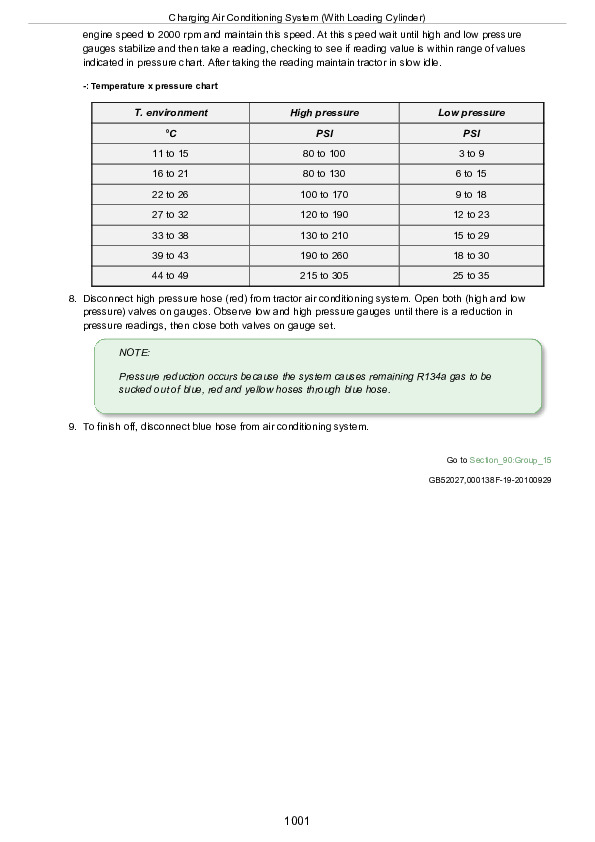
Posted on

John Deere 1654, 1854, 2054, 2104, 6165J, 6185J, 6205J, 6210J Tractors Repair Service Manual (TM802319)


INSTANT DOWNLOAD


Complete service repair technical manual for John Deere Tractors JD1654, JD1854, JD2054, JD2104, 6165J, 6185J, 6205J & 6210J (Asian Edition) 2WD / MFWD, with all the technical information to maintain, repair, rebuild like professional mechanics.

John Deere 1654, 1854, 2054, 2104, 6165J, 6185J, 6205J, 6210J Tractors workshop service repair manual includes:
* Numbered table of contents easy to use so that you can find the information you need fast.
* Detailed sub-steps expand on repair procedure information
* Numbered instructions guide you through every repair procedure step by step.
* Notes, cautions and warnings throughout each chapter pinpoint critical information.
* Bold figure number help you quickly match illustrations with instructions.
* Detailed illustrations, drawings and photos guide you through every procedure.
* Enlarged inset helps you identify and examine parts in detail.

tm802319 – 1654, 1854, 2054, 2104, 6165J, 6185J, 6205J,and 6210J Repair Manual Technical Manual.pdf
TM802314 Repair Technical Manual 1654、1854、2054、2104、6165J、6185J、6205J 和 6210J型修理手册
TM802319 Repair Technical Manual 1654, 1854, 2054, 2104, 6165J, 6185J, 6205J & 6210J Tractors (Asian Edition)

OMAL221436 Operator’s Manual JD1654, JD1854, JD2054, and JD2104 Tractors, (Asia, English)
OMAL221437 Operator’s Manual 拖拉机 JD1654、JD1854、JD2054 和 JD2104
OMAL221438 Operator’s Manual Tractors JD1654, JD1854, JD2054&JD2104
PC4667 Parts Catalog 1654 Tractor \ China Edition
PC4667Z Parts Catalog 1654 Tractor \ China Edition

Total Pages: 1,121 pages
File Format: PDF (bookmarked, ToC, Searchable, Printable, high quality)
Language: English

MAIN SECTIONS
Foreword
Safety
Safety Regulations
General Information
Specifications
Adjusting
Engine
Removing and Installing Engine
Fuel Systems, Air Intake, Cooling and Exhaust
Removal and Installation of Components
Speed Control
Fuel System
Air Intake System
Cooling System
Exhaust System
Electrical System
Connectors
Wiring Harnesses
Charging Circuit
Starter Motor Circuit
Fuses, Relays and Switches
Monitoring Systems
Electrical Components
Electronic Control Units
Removal and Installation of Electronic Control Units
Removal and Installation of Terminating Resistors
PowrQuad Transmission
Removing and Installing PowrQuad Module
Transmission Selectors Control
PowrQuad Module
Range Box
Drive Systems
Removing and Installing Component
U-Jointed Shafts and Torsional Damper
Front-Wheel Drive Clutch
Rear Differential
Hydraulic Pump Drive
Final Drives
Rear PTO
Steering and Brakes
Hydrostatic Steering
Brake Valve
Rear Wheel Brakes
Hydraulic System
Controls
Oil Filter, Charge Pump and Hydraulic Pump
Valves
Hitch
Selective Control Valves and Couplers
Miscellaneous
Removing and Installing Components
Main Chassis
Wheels
Center Link Bracket and Swinging Drawbar
Operator’s Cab
Removing and Installing Components
Air Conditioning System
Heating System
Operator’s Cab
Special Tools (Dealer-Fabricated)

TABLE OF CONTENTS
Section 05: Safety….21
Group 05: Safety Regulations….989
Live With Safety….23
Recognize Safety Information….346
Follow Safety Instructions….25
Handle Fluids Safely—Avoid Fires….26
Prevent Battery Explosions….27
Handle Batteries Safely….28
Prepare for Emergencies….29
Remove Paint Before Welding or Heating….30
Avoid High-Pressure Fluids….31
Engine Coolant….32
Prevent Machine Runaway….33
Avoid Heating Near Pressurized Fluid Lines….34
Work In Ventilated Area….35
Wear Protective Clothing….36
Practice Safe Maintenance….37
Park Machine Safely….38
Use Proper Lifting Equipment….39
Support Machine Safely….40
Work in Clean Area….41
Illuminate Work Area Safely….42
Service Machines Safely….43
Use Proper Tools….44
Service Tires Safely….45
Safe Servicing of Front-Wheel Drive….46
Use Seat Belt Properly….47
Keep ROPS Installed Properly….48
Dispose of Waste Properly….49
Section 10: General Information….203
Group 05: Specifications….959
Engine….53
PTO….54
POWRQUAD POWRQUAD is a registered trademark of the Deere & Company Transmission….50
Clutch….56
Brakes….57
Hydraulic System….58
Wheel Configurations….59
Drawbar….60
Dimensions….61
Electrical System….64
Capacities….65
Transmission and Hydraulic Oil….66
Front-Wheel Drive Axle Oil (Standard)….67
Metric Bolt and Screw Torque Values….69
Unified Inch Bolt and Screw Torque Values….71
Hydraulic system inch fitting torques….74
Hydraulic system metric fitting torques….75
Interpreting the Serial Number of Your Machine – 13 digits PIN….76
Interpreting the Serial Number of Your Machine – 17 digits PIN….77
Year of Production Table (Digit 5)….78
Transmission Type Table (Digit 6)….79
Serial Number Plates….80
Product Identification Number….81
Engine Serial Number….82
POWRQUAD POWRQUAD is a registered trademark of the Deere & Company Transmission Serial Number….50
Front-Wheel Drive Serial Number….84
POWRQUAD POWRQUAD is a registered trademark of the Deere & Company Differential Serial Number….50
Cab Serial Number….86
Group 10: Adjusting….50
Specifications….959
Using High-Pressure Washers….89
Preliminary Engine Test….90
Tractor Adjusting….91
Removing and Cleaning the Primary Air Cleaner Element….93
Checking the Air Cleaner Safety Element….94
Installing the Primary Filter Element….95
Checking Air Intake System Connections for Leaks….96
Checking Air Intake Hoses….97
Checking the Crankcase Vent Hose for Clogging….98
Cleaning Dirt from Radiator Screen….99
Adjust the Hood….100
Cleaning Radiator….102
Checking Expansion Tank Cap….103
Checking for Leaks in Radiator….104
Checking Engine Thermostat….105
Checking the Fuel Transfer Pump Operation….106
Cleaning Water Trap….107
Checking Fuel Filter….108
Bleed Fuel System….171
Check Transmission/Hydraulic System Oil Level….110
Cleaning Battery, Cables and Battery Box with a Clean Cloth….111
Checking Neutral Start Circuit….112
Checking Starter Motor….113
Checking Lighting Circuit….114
Final Engine Checks….115
Tractor Operation Check….116
Section 20: Engine….117
Group 00: Removing and Installing Engine….133
Special Tools….986
Specifications….959
Removing Engine….121
Installing Engine….133
Engine Mounting….140
Replace the Engine Mountings….142
Section 30: Fuel Systems, Air Intake, Cooling and Exhaust….146
Group 00: Removal and Installation of Components….146
Remove Engine Hood….150
Install Engine Hood….152
Remove Battery….154
Install Battery….155
Group 05: Speed Control….146
General Information….203
Specifications….959
Replace Accelerator Pedal Assembly….159
Remove Accelerator Pedal Potentiometer….160
Group 10: Fuel System….146
General Information….203
Removing the Fuel Tank….165
Installing the Fuel Tank….167
Replace Fuel Level Sensor….168
Replace the Fuel Transfer Pump….169
Changing the Fuel Filters….170
Bleed Fuel System….171
Group 15: Air Intake System….146
General Information….203
Air filter – Exploded view….174
Replacing Air Filter Restriction Sensor….175
Group 20: Cooling System….146
General Information….203
Specifications….959
Removing Radiator….179
Installing Radiator….186
Replacing Fan….187
Remove and Install the Charge Air Cooler….188
Removing and Installing the Expansion Tank….190
Removing and Installing Thermostat….193
Fill Cooling System with Coolant….194
Releasing Drive Belt Tension….196
Replacing Engine Fan Belt….197
Replacing Drive Belt Tensioner….200
Remove and Install Fan Console (with Mechanical Coolant Pump)….201
Group 30: Exhaust System….147
General Information….203
Specifications….959
Exhaust to Upper Right-Hand Side….205
Section 40: Electrical System….208
Group 05: Connectors….241
Special Tools….986
General….215
Using high-pressure washers….216
Disconnecting Electrical Circuits….343
Reconditioning Wire Ends….218
Installing a Terminal….219
WEATHER PACK Connectors….241
Metri-Pack Metri-Pack is a trademark of Delphi Connection Systems Connector with Rear Terminal Lock….208
Metri-Pack Metri-Pack is a trademark of Delphi Connection Systems Connector with Front Terminal Lock….208
Metri-Pack Metri-Pack is a trademark of Delphi Connection Systems Connectors….241
CAN BUS Terminating Resistor Connector….233
Electronic Control Unit Connectors….241
Connectors….241
CRIMP SNAP IN Connectors….246
KOSTAL Connectors….248
DEUTSCH Connectors….251
Individual Terminals….254
Fuse and Relay Boxes — Cab Tractors….256
Fuse and Relay Box — Open Station Tractors….259
Group 10: Wiring Harnesses….208
Disconnecting Electrical Circuits….343
Removing and Installing Wiring Harness W01 — Power link Box….264
Removing and Installing Wiring Harness W02 — Engine Wiring Harness (Cab Tractors)….265
Removing and Installing Wiring Harness W04 — Headlights….267
Removing and Installing Wiring Harness W08 — (Cab Tractors)….268
Removing and Installing Wiring Harness W09 — Hood (Cab Tractors)….270
Removing and Installing Wiring Harness W19 — Cab Roof….272
Removing and Installing Wiring Harness W26 — Fan and Air Conditioning….273
Removing and Installing Wiring Harness W28 — Front End of Transmission (Cab Tractors)….274
Removing and Installing Wiring Harness W30 — Rear End of Transmission (Cab Tractors)….276
Wiring Harness W31 — Power Take-Off for 7-Pin Socket….278
Group 15: Charging Circuit….209
Special Tools….986
Specifications….959
Repairing the Alternator….282
Disconnecting Electrical Circuits….343
Relieve Drive Belt Tension….284
Removing/Installing Alternator….285
Removing/Installing Alternator Pulley….287
Group 20: Starter Motor Circuit….209
Specifications….959
Repairing the Starting Motor….291
Disconnecting Electrical Circuits….343
Removing and Installing Starter Motor….293
Group 25: Fuses, Relays and Switches….209
Note….329
Special Tools….986
Specifications….959
Removing Hood Covers….299
Disconnecting Electrical Circuits….343
Fuse and Relay Box – Cab Tractors….303
Fuses and relays (Power Link Box)….307
Power Link Box- Components….308
Replacing Starter Switch….309
Replacing Brake Switches….310
Replacing Light Switch….311
Replacing Full/Low Beam Switch….312
Replacing Work Light Switches….313
Replacing Hazard Warning Light Switch….314
Replacing Turn Signal Switch….315
Replacing Horn Switch….316
Replacing Windshield Wiper and Windshield Washer Switch….317
Replacing Front-Wheel Drive Switch….318
Replacing Fan Switch….319
Replacing Differential Lock Switch….320
Replacing Rockshaft Remote Control Switch….321
Group 30: Monitoring Systems….210
Note….329
Note….329
Disconnecting Electrical Circuits….343
Replacing Engine Oil Pressure Sensor Unit (B04)….326
Replacing Coolant Temperature Gauge Sensor Unit (B08)….327
Group 40: Electrical Components….210
Note….329
Special Tools….986
Specifications….959
Disconnecting Electrical Circuits….343
Replacing Socket of 7-Terminal Power Outlet….333
Replacing Service Socket….335
Removing Windshield Wiper Motor….337
Adjusting the Headlights….339
Section 45: Electronic Control Units….341
Group 05: Removal and Installation of Electronic Control Units….341
Disconnecting Electrical Circuits….343
Instructions when Replacing a VIN Control Unit….344
Instructions when Replacing a Control Unit….345
Safety Information….346
Replace BCU Control Unit….347
Replace ECU Control Unit….349
Group 10: Removal and Installation of Terminating Resistors….341
Terminating Resistors for the CAN BUS (Cab)….352
Section 55: PowrQuad Transmission….354
Group 00: Removing and Installing PowrQuad Module….354
Special Tools….986
Special Tool (Own Fabrication)….361
Specifications….959
Removing PowrQuad Housing….363
Installing PowrQuad Housing….367
Removing Range Box….369
Installing Range Box….372
Final installation….374
Group 05: Transmission Selectors Control….354
Specifications….959
Reconditioning Gear Shift Mechanism….377
Reconditioning of Range Shift Mechanism….380
Checking and Adjusting Gear Shift Units….983
Adjusting Clutch Pedal….388
Group 10: PowrQuad Module….354
Special Tools….986
Other Material….996
Specifications….959
Transmission Components….397
Replacing Neutral Start Circuit (Mechanically Actuated PowrQuad Module)….398
Removing and Installing Oil Filter Base….399
Replacing Oil Filter….400
Removing and Installing Front Valve Housing….401
Removing and Installing Front Valve Housing Valves (With Mechanically Actuated PowrQuad Module)….404
Removing and Installing Transmission Front Cover….417
Removing and Installing Transmission Front Cover Valves (With Mechanically Actuated PowrQuad Module)….419
Removing Clutch Pedal Valve (Mechanically Actuated PowrQuad Module)….424
Removing and Installing Shift Valve Housing (With Mechanically Actuated PowrQuad Module)….430
Removing and Installing Shift Valve Housing Valves (With Mechanically Actuated PowrQuad Module)….433
Removing Transmission Oil Pump….437
Servicing Transmission Oil Pump….438
Installing Transmission Oil Pump….444
Removing Planetary Drive Gears….445
Repairing Planetary Drive Gears….447
Installing Planetary Drive Gears….453
Removing B1 Brake Housing….458
Reconditioning B1 Brake….459
Installing B1 Brake Housing….461
Removing B2-B3 Brake Housing….462
Reconditioning B2 Brake….463
Reconditioning B3 Brake….465
Installing B2-B3 Brake Housing….468
Removing C4 Clutch….469
Reconditioning C4 Clutch….470
Installing C4 Clutch….481
Removing Reverse Brake….482
Servicing Reverse Brake….483
Installing Reverse Brake….486
Removing Forward Clutch with Planetary Drive (Forward/Reverse)….487
Servicing Forward Clutch with Planetary Drive (Forward/Reverse)….488
Installing Forward Clutch with Planetary Drive (Forward/Reverse)….502
Replacing Output Shaft….504
Group 20: Range Box….355
Special Tools….986
Other Material….996
Specifications….959
Cross-Sectional View—Input Drive Shaft….510
Remove Intermediate Shaft….511
Repair Intermediate Shaft….514
Remove Input Drive Shaft….516
Repair Input Drive Shaft….518
Install Input Drive Shaft….522
Adjust Input Drive Shaft End Play….524
Intermediate Shaft Installation And Cone Point Adjustment….526
Adjust Intermediate Shaft End Play….531
Remove, Repair, and Install Shift Cover….533
Repair Shifting Mechanism….535
Repair Park Lock….537
Adjust Range Shift….539
Replace Speed Sensor….540
Section 56: Drive Systems….542
Group 00: Removing and Installing Component….542
Special Tools….986
Special Tools (Dealer-Fabricated)….918
Specifications….959
Removing MFWD Clutch….554
Installing MFWD Clutch….557
Removing Differential Housing….558
Installing Differential Housing….566
Removing Final Drive….569
Installing Final Drive….574
Removing Rear PTO….577
Installing Rear PTO….580
Group 05: U-Jointed Shafts and Torsional Damper….542
Special Tools….986
Use of Special Tool KJD10426….584
Specifications….959
Removing MFWD Universal-Joint Drive Shaft….586
Repairing MFWD Universal-Joint Drive Shaft….587
Installing MFWD Universal-Joint Drive Shaft….591
Removing Engine Universal-Joint Drive Shaft….593
Removing Torsional Damper….594
Replacing Torsional Damper Bearings….595
Installing Torsional Damper….596
Installing Engine Universal-Joint Drive Shaft….598
Group 10: Front-Wheel Drive Clutch….56
Special Tools….986
Specifications….959
MFWD Clutch Repair Instructions….602
MFWD Clutch — Cross-Sectional View….603
Disassembling MFWD Clutch….605
Disassembling MFWD Clutch Assembly….607
MFWD Clutch Exploded View….609
Mounting MFWD Clutch Assembly….611
Mounting MFWD Clutch….615
Group 15: Rear Differential….543
Special Tools….986
Specifications….959
Rear Differential Repair Instructions….623
Removing Rear Differential….625
Rear Differential — Cross Sectional View….628
Disassembling Rear Differential….630
Rear Differential — Exploded View….634
Assembling Rear Differential….636
Adjust Rear Differential Preload….642
Adjust Rear Differential Backlash….644
Group 20: Hydraulic Pump Drive….543
Special tools….647
Specifications….959
Removing and Disassembling Pump Drive Pinion….649
Removing and Disassembling Pump Drive Gear….652
Assembling and Installing Pump Drive Gear….654
Assembling and Installing Pump Drive Pinion….657
Checking and Adjusting Play of Pump Drive Pinion….660
Group 25: Final Drives….543
Special Tools….986
Specifications….959
Final Drive Repair Instructions….666
Checking Final Drive Shaft and Retainer….668
Final Drive Housing — Exploded View….669
Removing Planetary Carrier….671
Disassembling Planetary Carrier….673
Planetary Carrier — Exploded View….675
Assembling Planetary Carrier….676
Final Drive Housing — Cross Sectional View….678
Removing Final Drive Housing to Axle….679
Disassembling and Assembling Final Drive Housing….681
Disassembling and Assembling Axle….682
Installing Final Drive Housing to Axle….684
Installing Planetary Carrier….685
Final Assembly….687
Group 30: Rear PTO….54
Special Tools….986
Rear PTO – Specifications….959
Replacing Output Shaft Seal Ring….691
Rear PTO Clutch – Cross Sectional View….692
Rear PTO Clutch – Exploded View….694
Removing Rear PTO Clutch….695
Reconditioning Rear PTO Clutch….698
Reconditioning Rear PTO Brake….707
Installing Rear PTO Clutch….708
Rear PTO Drive Train – Cross Sectional View….711
Rear PTO Drive Train – Exploded View….712
Removing Rear PTO Drive Train….714
Reconditioning Output Shaft….717
Reconditioning Countershaft….722
Installing Rear PTO Drive Train….724
Adjust Taper Roller Bearing of Countershaft….725
Adjust Tapered Roller Bearing of Bearing Support….727
Reconditioning Rear PTO Solenoid Valve….730
Removing PTO Modulating Valve….732
Reconditioning PTO Modulating Valve….733
Installing PTO Modulating Valve….735
Replace B06 – Rear PTO Speed Sensor….736
Recondition the Oil Sight-Glass….737
Section 60: Steering and Brakes….740
Group 05: Hydrostatic Steering….740
Special Tools….986
Specifications….959
Preliminary Work….744
Disconnect/Connect Steering or Brake Hoses….745
Steering Valve – Removing….747
Steering Valve – Cross Sectional View….750
Disassembling Steering Valve….751
Exploded View of Steering Valve….755
Mounting Steering Valve….757
Adjusting Shock Valves….765
Steering – Exploded View….767
Steering Column – Exploded View….769
Installing Steering Valve….770
Group 15: Brake Valve….777
Special Tools….986
Specifications….959
Brake Valve Repair Instructions….776
Brake Valve….777
Group 20: Rear Wheel Brakes….57
Rear Brakes, Specifications….959
Rear Wheel Brakes – Exploded View….788
Removing Rear Brakes….789
Reconditioning Rear Brakes….791
Installing Rear Brakes….793
Replacing Retraction Pins on the Rear Wheel Brakes….795
Section 70: Hydraulic System….798
Group 05: Controls….798
Specifications….959
Selective Control Valves — Removing and Installing Actuating Elements….802
Selective Control Valves — Adjusting Bowden Cable….806
Group 10: Oil Filter, Charge Pump and Hydraulic Pump….798
Other Material….996
Specifications….959
Removing and Installing Hydraulic Oil Mesh Filter….810
Removing and Installing Hydraulic Oil Filter….813
Removing and Installing Charge Pump….817
Charge Pump – Checking the Lube Oil Valve….821
Hydraulic Oil Reservoir — Restrictor….822
Hydraulic Pump – Removing and Installing Pressure-and-Flow Controller….823
Hydraulic Pump – Reconditioning Pressure-and-Flow Controller….825
Removing and Installing Hydraulic Pump….827
Hydraulic Pump – Exploded View….832
Disassembling Hydraulic Pump….834
Assembling Hydraulic Pump….835
Group 15: Valves….798
Special Tools….986
Specifications….959
Hydraulic System Repair Instructions….845
Removing Priority 1 Control Block….847
Installing Priority 1 Control Block….848
Reconditioning Priority 1 Control Block….849
Removing Priority 3 Control Block….851
Installing Priority 3 Control Block….855
Recondition Priority 3 Control Block….859
Group 20: Hitch….798
Other Material….996
Specifications….959
Rockshaft Valve, Removing and Installing the Stepper Motor….864
Remove Rockshaft Valve….866
Recondition the Rockshaft Valve….868
Install the Hitch Valve….872
Rockshaft – Removg and Installing Position Sensor and Toothed Segment….875
Rockshaft – Removing and Installing Rockshaft….878
Rockshaft – Removing Rockshaft Cylinders….882
Rockshaft – Reconditioning Lift Cylinder….883
Rockshaft – Install Rockshaft Cylinders….886
Rockshaft – Removing and Installing Draft Load Potentiometer and Draft Link Support….887
Group 25: Selective Control Valves and Couplers….799
Specifications….959
Selective Control Valves (SCVs) and Couplers Repair Instructions….893
Remove the Selective Control Valves (SCVs)….895
Recondition the Selective Control Valves (M-SCVs 100)….897
Recondition the Selective Control Valves (M-SCVs 200)….901
Install the Selective Control Valves (SCVs)….904
Selective Control Valves (SCVs) – Reconditioning the Couplers….909
Section 80: Miscellaneous….911
Group 00: Removing and Installing Components….911
Special Tools….986
Special Tools (Dealer-Fabricated)….918
Specifications….959
Removing Main Chassis….920
Installing Main Chassis….925
Removing Front-Wheel Drive Axle….928
Installing Front-Wheel Drive Axle….931
Group 05: Main Chassis….911
Specifications….959
Reconditioning Main Chassis….935
Group 15: Wheels….911
Essential, Recommended and Fabricated Tools….937
Specifications….959
Service Heavy-Duty Wheel Clamps….939
Group 20: Center Link Bracket and Swinging Drawbar….949
Specifications….959
Checking Swinging Drawbar Wear….947
Installing Center Link Bracket….948
Swinging Drawbar….949
Adjusting Retention Rod….951
Section 90: Operator's Cab….952
Group 00: Removing and Installing Components….952
Special Tools….986
Dealer-Manufactured Special Tools….986
Specifications….959
Swinging Up Operator's Cab….960
Swinging Down Operator's Cab….969
Removing Operator's Cab or Platform….971
Installing Operator's Cab or Platform….979
Checking and Adjusting Gear Shift Units….983
Group 15: Air Conditioning System….952
Special Tools….986
Tightening Torque for Refrigerant Hoses….988
Safety Regulations….989
Handling Refrigerant….990
In the Event of an Emergency….991
Safety Equipment….992
Storage of Refrigerant Containers….993
Refrigerant R134a….994
Important….995
Other Material….996
Specification….997
Filling the Cylinder….998
Charging Air Conditioning System (With Loading Cylinder)….1000
Adding Oil to the Air Conditioning System….1002
Leak Test….1003
Evacuate Air Conditioning System….1004
Cleaning the Air Conditioning System….1006
Separating Compressor….1007
Checking Compressor Level….1008
Disassembling Compressor Clutch….1009
Checking Clutch Hub Separation….1012
Installing Compressor….1013
Separating and Installing Condenser….1014
Separating and Installing Drier….1015
Replacing Expansion Valve….1016
Separating and Installing Evaporator and Expansion Valve….1017
Installing Condensation Water Drain Hoses….1019
Layout of Condensation Water Drain Hoses….1020
Separating and Installing Thermostat….1021
Separating and Installing High/Low Pressure Switch….1022
Vacuum Pump — General Information….1023
Group 20: Heating System….953
Fan and Heater, Disassembling….1026
Removing Cab Air Filter….1028
Separating and Installing Fan….1030
Separating and Installing Heater Regulator….1031
Separating Heater/Evaporator Housing….1032
Group 25: Operator's Cab….953
Removing Cab Frame….1035
Cab Mounting Torques….1036
Removing and Installing Windshield….1038
Removing and Installing Rear Window….1039
Installing Door Lock….1041
Adjusting Window Contact Pressure….1043
Removing and Installing Operator's Cab Door….1044
Removing and Installing Sun-Visor Roller….1046
Section 99: Special Tools (Dealer-Fabricated)….1047
Group 05: Special Tools (Dealer-Fabricated)….918
DFLX1 – Adapter Strut….1049
DFLX7 – Turning Device….1063
DFLX14 – Suspended MFWD Axle Housing Bracket….1051
DFLX29 – Support….1052
Lifting Device….1053
Holding Device….1054
Suspension Eyes for Operator's Cab….1055
Holding Tool….1056
Wooden Block….1057
DFRW79 – Piston Holding Tool….1058
Socket Wrench Insert….1065
Seal Installer….1064
Driver….1061
Assembly and Guide Mandrels….1062
Turning Device….1063
Seal Installer….1064
Socket Wrench Insert….1065
Special Wrench….1066
Quick Coupler Securing Support….1067
Lifting Tool….1068

John Deere 1654, 1854, 2054, 2104, 6165J, 6185J, 6205J, 6210J Tractors Repair Service Manual (TM802319)


INSTANT DOWNLOAD


Posted on

Mercedes-Benz GLE-Class Coupé (Model C292) Repair Service Manual 2015-2019


INSTANT DOWNLOAD


Complete service repair manual with Electrical Wiring Diagrams for Mercedes-Benz GLE-Class Coupé (Model C292) 2015-2019, with all the technical information to maintain, diagnose, repair, and rebuild like professional mechanics.

Mercedes-Benz GLE-Class Coupé (Model C292) 2015-2019 workshop service repair manual includes:
* Numbered table of contents easy to use so that you can find the information you need fast.
* Detailed sub-steps expand on repair procedure information
* Numbered instructions guide you through every repair procedure step by step.
* Troubleshooting and electrical service procedures are combined with detailed wiring diagrams for ease of use.
* Notes, cautions and warnings throughout each chapter pinpoint critical information.
* Bold figure number help you quickly match illustrations with instructions.
* Detailed illustrations, drawings and photos guide you through every procedure.
* Enlarged inset helps you identify and examine parts in detail.

PRODUCT DETAILS:
Total Pages: 2,011 pages
File Format: PDF (Internal Links, Bookmarked, Table of Contents, Searchable, Printable, high quality)
Language: English

Mercedes-Benz GLE-Class Coupé (Model C292) Repair Service Manual 2015-2019.pdf

TABLE OF CONTENTS
00_Overall Vehicle…3
00.00 – Overview of new products_features for market launch (sn00.00-p-0080e)…6
00.00 – Service Information AMG After Sales Portal (si00.00-p-0125a)…10
00.00 – Service Information Exclusion of liability for third-party retrofits (si00.00-p-0025a)…11
00.00 – Service Information Operation items for test drives (si00.00-p-0009a)…12
00.00 – Service Information Processing of warranty and goodwill claims (si00.00-p-0116a)…14

60.00 – Check vehicle underside in visible area for signs of damage, leaks and corrosion (ap60.00-p-0051b)…1266
60.00 – Service information Measuring and straightening systems (si60.00-p-0001a)…1268
60.00 – Stamp in vehicle identification number (ar60.00-p-0800rqa)…1269
61_Substructure…1271
61.30 – Remove_install underbody paneling (ar61.30-p-1001gq)…1272
62_Front End & Fire Wall…1274
62.20 – Partially replace upper front longitudinal member (ar62.20-p-1287gq)…1275
62.20 – Replace complete wheel well (ar62.20-p-1200gq)…1277
62.20 – Replace longitudinal member front section (ar62.20-p-1260gq)…1280
62.30 – Replace complete front end assembly together with reinforcement (ar62.30-p-1570gq)…1282
62.30 – Replace radiator support (without straightening bench) (ar62.30-p-1510gq)…1287
62.30 – Replace side reinforcement (ar62.30-p-1401gq)…1289
63_Side Wall…1291
63.10 – Completely replace C and D-pillar side wall (ar63.10-p-0800gqc)…1292
63.10 – Remove_install outer rear wheel well (ar63.10-p-0665gqx)…1294
63.10 – Remove_install outer side wall (ar63.10-p-0805gqc)…1296
63.20 – Remove_install B-pillar outer section (ar63.20-p-1121gqx)…1298
63.20 – Replace complete A-pillar together with side longitudinal member (ar63.20-p-1150gq)…1301
63.20 – Replace complete B-pillar (ar63.20-p-1350gqx)…1304
63.30 – Partially replace outer side longitudinal member (ar63.30-p-1050gq)…1307
63.40 – Replace cross member below left front seat (ar63.40-p-1190gz)…1309
64_Rear Wall & Rear End…1311
64.20 – Partially replace side rear end (ar64.20-p-1015gqc)…1312
64.20 – Replace complete bottom rear center section (ar64.20-p-1000gq)…1315
64.20 – Replace spare tire well (ar64.20-p-1245gq)…1318
65_Roof…1321
65.10 – Remove_install rear section on center roof paneling (ar65.10-p-5760gqc)…1322
65.10 – Replace complete center roof paneling (ar65.10-p-1000gqc)…1325
65.20 – Remove_install front roof frame (ar65.20-p-1006gqc)…1328
67_Windows…1330
67.10 – Remove, install windshield (ar67.10-p-1700gqc)…1331
67.10 – Service Information Stone mark repairs on laminated glass windows (si67.10-p-0001a)…1335
67.10 – Service information bulletin Damage code for windshield replacement (si67.10-p-0004a)…1336
67.20 – Remove_install rear window (ar67.20-p-5145gqc)…1337
67.30 – Remove_install side window (ar67.30-p-0005gqc)…1340
68_Interior Equipment…1342
68.00 – Check first aid kit (ap68.00-p-6850ew)…1344
68.00 – Cleaning the vehicle interior (ap68.00-p-1000zz)…1347
68.10 – Remove_install center air nozzle (ar68.10-p-1150gq)…1348
68.10 – Remove_install cover below instrument panel (left) (ar68.10-p-1500gq)…1349
68.10 – Remove_install cover below instrument panel (right) (ar68.10-p-1520gq)…1350
68.10 – Remove_install dashboard carrier (ar68.10-p-1111gq)…1351
68.10 – Remove_install dashboard lower section on driver side (ar68.10-p-1505gq)…1353
68.10 – Remove_install dashboard top section (ar68.10-p-1020gq)…1355
68.10 – Remove_install glove compartment (ar68.10-p-1400gq)…1357
68.10 – Remove_install lock cylinder on glove compartment lock (ar68.10-p-1250w)…1359
68.10 – Remove_install side air vent (ar68.10-p-1100gq)…1361
68.10 – Remove_install trim strip on dashboard (ar68.10-p-1180gq)…1362
68.20 – Remove_install center console (ar68.20-p-2000gq)…1364
68.20 – Remove_install cover on center console (ar68.20-p-2350gqa)…1366
68.20 – Remove_install front beverage holder (ar68.20-p-2240gq)…1368
68.20 – Remove_install front floor covering (left) (ar68.20-p-2050gq)…1369
68.20 – Remove_install front floor covering (right) (ar68.20-p-2070gq)…1370
68.20 – Remove_install rear center console (ar68.20-p-2020gq)…1371
68.20 – Remove_install rear floor covering (ar68.20-p-4800gqc)…1373
68.20 – Remove_install stowage compartment (ar68.20-p-2320gq)…1374
68.30 – Remove_install door sill molding (ar68.30-p-4100gq)…1375
68.30 – Remove_install headliner (ar68.30-p-4300gqc)…1376
68.30 – Remove_install paneling on A-pillar (ar68.30-p-4050gqc)…1379
68.30 – Remove_install paneling on B-pillar (ar68.30-p-4700gq)…1380
68.30 – Remove_install side paneling in trunk (ar68.30-p-4800gqc)…1382
68.30 – Remove_install trim at C-pillar (ar68.30-p-4490gqc)…1384
68.30 – Service Information bulletin Surface damage by scent dispenser (si68.30-p-0002a)…1385
68.40 – Remove_install inside rearview mirror (ar68.40-p-0001gqa)…1386
72_Doors…1388
72.10 – Adjust front door (ar72.10-p-0550cw)…1391
72.10 – Disassemble_assemble front door liner (ar72.10-p-1030gq)…1401
72.10 – Remove_install door frame seal (ar72.10-p-2120gz)…1404
72.10 – Remove_install door module (ar72.10-p-0900gq)…1406
72.10 – Remove_install front door (ar72.10-p-0500gq)…1408
72.10 – Remove_install front door lining (ar72.10-p-1000gq)…1410
72.10 – Remove_install front door lock (ar72.10-p-4011gq)…1412
72.10 – Remove_install front door lock cylinder (ar72.10-p-4015gqc)…1413
72.10 – Remove_install front door side window (ar72.10-p-1961gqc)…1414
72.10 – Remove_install hinge of front door (ar72.10-p-2662gqc)…1416
72.10 – Remove_install inner paneling at window frame of front door (ar72.10-p-6580gz)…1419
72.10 – Remove_install outside door handle on front door (ar72.10-p-2400gz)…1420
72.10 – Remove_install seal for side window on front door (ar72.10-p-1906gqc)…1422
72.10 – Remove_install sealing rail on outside (ar72.10-p-1700gqc)…1423
72.10 – Remove_install window guide rail (ar72.10-p-1500gq)…1424
72.12 – Adjust rear door (ar72.12-p-0650cw)…1425
72.12 – Assemble_disassemble door liner in rear door (ar72.12-p-1040gq)…1433
72.12 – Remove_install door frame seal on rear door (ar72.12-p-1015gz)…1435
72.12 – Remove_install fixed window in rear door (ar72.12-p-1970gz)…1437
72.12 – Remove_install hinge of rear door (ar72.12-p-2661gqc)…1438
72.12 – Remove_install inner paneling on rear door window frame (ar72.12-p-1012gz)…1440
72.12 – Remove_install inner sealing rail on rear door (ar72.12-p-1013gz)…1441
72.12 – Remove_install outer rear door handle (ar72.12-p-2410gqc)…1442
72.12 – Remove_install rear door (ar72.12-p-0600gq)…1443
72.12 – Remove_install rear door lining (ar72.12-p-1010gq)…1445
72.12 – Remove_install rear door lock (ar72.12-p-2510gq)…1447
72.12 – Remove_install rear door module (ar72.12-p-0103gq)…1448
72.12 – Remove_install rear door side window (ar72.12-p-1961gq)…1450
72.12 – Remove_install sealing for side window on rear door (ar72.12-p-0001gqc)…1452
72.12 – Remove_install window guide rail for rear door (ar72.12-p-1500gq)…1454
72.20 – Remove, install liftgate door panel (ar72.20-p-6445gqc)…1455
72.20 – Remove_ install trunk lid lock (ar72.20-p-1022gqc)…1457
72.20 – Remove_install liftgate (ar72.20-p-1020gqc)…1458
72.20 – Remove_install rear flap hinge (ar72.20-p-1024gqc)…1460
72.20 – Removing and installing rear spoiler (ar72.20-p-4000gqc)…1462
72.29 – Overview of system components for power windows (gf72.29-p-9993gn)…1463
72.29 – Remove_install electric liftgate control unit (ar72.29-p-0003gqc)…1465
72.29 – Remove_install electric liftgate drive unit (ar72.29-p-5590gqc)…1466
72.29 – Remove_install front door control unit (ar72.29-p-1000gq)…1468
72.29 – Remove_install front door power window switch group (ar72.29-p-0110nkb)…1469
72.29 – Remove_install rear door control unit (ar72.29-p-1100gq)…1471
72.29 – Remove_install switches for rear door power windows (ar72.29-p-0002nkb)…1472
72.29 – Remove_installing front door power window motor (ar72.29-p-1860gz)…1473
72.29 – Removing and installing rear door power windows (ar72.29-p-1880gz)…1474
72.30 – Remove_install closing assist motor for electric liftgate (ar72.30-p-0001gqc)…1476
77_Sliding Roor, Soft Top, Top Attachments…1477
77.20 – Overview of system components, panoramic sliding sunroof (gf77.20-p-9991gn)…1479
77.20 – Panoramic sliding roof – clean and lubricate guide mechanism (ap77.20-p-7732a)…1480
77.21 – Adjust front panoramic glass roof (ar77.21-p-0501gqc)…1482
77.21 – Remove, install roller sun blind on panoramic sliding roof (ar77.21-p-0215gqc)…1484
77.21 – Remove_install drive cable for panoramic sliding sunroof (ar77.21-p-0240ew)…1486
77.21 – Remove_install drive cable for panoramic sunroof roller sun blind (ar77.21-p-0230gqc)…1488
77.21 – Remove_install front glass cover (ar77.21-p-7010gqc)…1489
77.21 – Remove_install front panoramic glass roof (ar77.21-p-0500gq)…1491
77.21 – Remove_install motor for roller sun blind on panoramic sliding roof (ar77.21-p-0490gqc)…1493
77.21 – Remove_install outer support for panoramic front glass roof (ar77.21-p-0520ew)…1494
77.21 – Remove_install panoramic roof frame (ar77.21-p-0800gqc)…1495
77.21 – Remove_install panoramic roof front glass roof rubber bellows (ar77.21-p-0530ew)…1498
77.21 – Remove_install panoramic roof wind deflector (ar77.21-p-0100gqc)…1499
77.21 – Remove_install panoramic sliding roof motor (ar77.21-p-6995gqc)…1501
77.21 – Remove_install panoramic sunroof drive guide rail (ar77.21-p-0430ew)…1502
77.21 – Remove_install roller sun blind guide rail (ar77.21-p-0231gqc)…1504
77.21 – Remove_install seal for panoramic front glass roof (ar77.21-p-0540sx)…1505
80_Central Locking System, Convenience Operation, Drive Authorization Systems…1507
80.00 – Overview of system components for theft protection and locking (gf80.00-p-9999gn)…1508
80.20 – Remove_install fuel filler flap CL element (ar80.20-p-2300gq)…1516
80.35 – Remove_install Keyless Go control unit (ar80.35-p-0001gq)…1517
80.35 – Remove_install batteries for remote control key (ar80.35-p-4210gq)…1518
80.50 – Removing and installing ATA alarm signal siren (ar80.50-p-9840gq)…1519
82_Electrical System, Body…1521
82.00 – Service Information Repair of damaged Audio_COMAND wiring harnesses (si82.00-p-0004a)…1526
82.10 – Check and correct the adjustment of the headlamps (ap82.10-p-8260i)…1527
82.10 – Check function of headlamp range adjustment (ap82.10-p-8250ew)…1529
82.10 – Check, adjust low beams (ap82.10-p-8263ba)…1530
82.10 – Check, adjust low beams (ap82.10-p-8263da)…1537
82.10 – Check, adjust low beams (ap82.10-p-8263ea)…1541
82.10 – Check, adjust low beams (ap82.10-p-8263p)…1545
82.10 – Overview of exterior lights system components (gf82.10-p-9998gn)…1552
82.10 – Remove_install LED module for front lamp unit (ar82.10-p-4656gqc)…1558
82.10 – Remove_install center high-mounted stop lamp (ar82.10-p-5375gqc)…1560
82.10 – Remove_install driving lights actuation module (ar82.10-p-4650gqc)…1561
82.10 – Remove_install fan for lamp unit (ar82.10-p-4742gqc)…1563
82.10 – Remove_install headlamp control unit (ar82.10-p-4660gqc)…1565
82.10 – Remove_install headlamp range adjustment front axle sensor (ar82.10-p-4083gq)…1567
82.10 – Remove_install lamp unit (ar82.10-p-4730gqc)…1569
82.10 – Remove_install rear axle headlamp range adjustment sensor (ar82.10-p-4084gq)…1571
82.10 – Remove_install taillamp (ar82.10-p-4905gqc)…1573
82.10 – Remove_install taillamp, trunk lid (ar82.10-p-4915gqc)…1574
82.10 – Table of contents for function description of exterior lights (gf82.10-p-0999gn)…1575
82.20 – Overview of interior illumination (IBL) system components (gf82.20-p-9997gn)…1577
82.20 – Remove_install front overhead control panel (ar82.20-p-1100gqc)…1583
82.20 – Retrofit illuminated door sill molding (an82.20-p-0001gqc)…1584
82.30 – Check wiper arms and adjust (ar82.30-p-6000gz)…1587
82.30 – Inspect wiper blade (ap82.30-p-8253g)…1592
82.30 – Overview – Function check of windshield wipers, windshield washer system and headlamp cleaning system (ap82.30-p-8249u)…1594
82.30 – Overview of system components for windshield wiper system (gf82.30-p-9996gn)…1595
82.30 – Remove and install wiper arm (ar82.30-p-6100gqa)…1597
82.30 – Remove and install wiper arm (ar82.30-p-6100gz)…1600
82.30 – Remove_install rain_light sensor (ar82.30-p-7800gqc)…1602
82.30 – Remove_install wiper system (ar82.30-p-6400gz)…1604
82.30 – Service Information Bulletin Wiper blades (si82.30-p-0011c)…1606
82.35 – Clean water drain (ap82.35-p-8232a)…1608
82.35 – Remove_install washer fluid reservoir of windshield washer system (ar82.35-p-6000gz)…1610
82.35 – Remove_install windshield washer hose (ar82.35-p-6980gq)…1612
82.35 – Remove_install windshield washer hose (ar82.35-p-6980gqc)…1614
82.35 – Service information Wiping quality and noise development (si82.35-p-0002a)…1615
82.35 – Windshield washer system – inspect fluid level, adjust to correct level (ap82.35-p-8210b)…1616
82.35 – Windshield wipers, windshield washer system – operational inspection (ap82.35-p-8252b)…1617
82.60 – Remove_install DVD player (ar82.60-p-7505gq)…1619
82.60 – Remove_install display in rear (ar82.60-p-7720gqc)…1620
82.60 – Remove_install media interface control unit (ar82.60-p-1030gq)…1622
82.60 – Remove_install radio (ar82.60-p-7502gq)…1623
82.60 – Remove_install radio display (ar82.60-p-7722gqc)…1625
82.60 – Remove_install satellite radio control unit (ar82.60-p-7545gq)…1626
82.60 – Retrofit larger display (an82.60-p-0023gqc)…1629
82.60 – Retrofit rear entertainment system (an82.60-p-0013gqc)…1630
82.60 – Service Information Return delivery process for customer-owned CDs_DVDs and other media (si82.60-p-0010a)…1633
82.61 – Service information Notes on handling Garmin MAP PILOT card navigation (si82.61-p-0002a)…1634
82.62 – Remove_install Bluetooth antenna (ar82.62-p-8980gqa)…1636
82.62 – Remove_install TV antenna amplifier (ar82.62-p-8302gqc)…1638
82.62 – Remove_install amplifier for sound system (ar82.62-p-7723gq)…1640
82.62 – Remove_install amplifier for sound system (ar82.62-p-7723gqa)…1641
82.62 – Remove_install bass module speaker (ar82.62-p-7839gq)…1644
82.62 – Remove_install loudspeakers in front doors (ar82.62-p-7845gz)…1646
82.62 – Remove_install loudspeakers in rear doors (ar82.62-p-7874gz)…1647
82.62 – Remove_install radio antenna amplifier (ar82.62-p-8301gqc)…1648
82.62 – Removing and installing keyless go antenna (ar82.62-p-8000gq)…1649
82.62 – Removing and installing loudspeaker in instrument panel (ar82.62-p-7833gq)…1651
82.70 – Remove_install E-net compensator (ar82.70-p-0010gqc)…1652
82.70 – Remove_install GSM-net compensator (ar82.70-p-0040gqc)…1653
82.70 – Remove_install antenna (ar82.70-p-8951gqc)…1654
82.70 – Remove_install antenna cover (ar82.70-p-8952ew)…1655
82.70 – Remove_install contact plate for cell phone holder (UPCI (UHI)) in the armrest (ar82.70-p-8919gq)…1657
82.70 – Removing and installing hands-free system speaker (ar82.70-p-8968z)…1658
82.85 – Overview of system components, telematics (gf82.85-p-9999gn)…1659
82.85 – Read out map data status from COMAND navigation system (ap82.85-p-8251d)…1666
82.85 – Remove_install WLAN antenna (ar82.85-p-0004gqa)…1667
82.85 – Remove_install additional fan for COMAND (ar82.85-p-0005gq)…1669
82.85 – Remove_install telematics services communications module control unit (ar82.85-p-0020gqc)…1670
82.85 – Service Information COMAND online monitoring (si82.85-p-0021a)…1672
82.85 – Service Information Feedback on incomplete or faulty map data of the navigationsystem (si82.85-p-0012a)…1674
82.85 – Service Information Free map updates for COMAND (si82.85-p-0019a)…1675
82.85 – Service information Copy protection in navigation unit with hard-disk navigation (si82.85-p-0018a)…1678
82.85 – Table of contents for function description, telematics (gf82.85-p-0993gn)…1681
82.85 – Update map data for navigation system (ar82.85-p-0100a)…1683
82.95 – Remove_install emergency call system antenna (ar82.95-p-0017gqc)…1685
83_Climate Control…1686
83.00 – Replace combination filter (ap83.00-p-8384c)…1689
83.00 – Replace dust filter for heating_air conditioning (ap83.00-p-8381gq)…1691
83.10 – Remove and install left blend air flap actuator motor (ar83.10-p-2002gq)…1693
83.10 – Remove and install left center nozzle air flap actuator motor (ar83.10-p-2015gq)…1694
83.10 – Remove and install right blending air actuator motor (ar83.10-p-2003gq)…1696
83.10 – Remove and install right center nozzle air flap actuator motor (ar83.10-p-2016gq)…1697
83.10 – Remove_install actuator motor for left defroster flap (ar83.10-p-2004gq)…1699
83.10 – Remove_install actuator motor for left footwell flap (ar83.10-p-2006gq)…1701
83.10 – Remove_install actuator motor for right defroster vent flap (ar83.10-p-2005gq)…1702
83.10 – Remove_install actuator motor for right footwell flap (ar83.10-p-2007gq)…1704
83.10 – Removing and installing rear air nozzle (ar83.10-p-4800gq)…1705
83.25 – Remove and install heat exchanger (ar83.25-p-1100gq)…1706
83.25 – Remove_install water collector (ar83.25-p-1402gq)…1707
83.25 – Remove_install_replace heater circulation pump (ar83.25-p-1170gq)…1709
83.25 – Removing and installing blower motor (ar83.25-p-1200gz)…1710
83.30 – Check air conditioning system for leakage (ar83.30-p-1761gq)…1711
83.30 – Check evaporator for leaks (ar83.30-p-5550q)…1712
83.30 – Cleaning the evaporator (ar83.30-p-5555gq)…1717
83.30 – Correct oil level in air conditioning system after replacing parts (ar83.30-p-5252pc)…1719
83.30 – Correct oil level in air conditioning system in the event of repair or slow refrigerant loss (ar83.30-p-5251pc)…1726
83.30 – Drain, evacuate and recharge air conditioning, check for proper operation and check for leaks (ar83.30-p-1760cw)…1729
83.30 – Remove and install evaporator temperature sensor (ar83.30-p-8085gq)…1741
83.30 – Remove_install air conditioner housing (ar83.30-p-5200gq)…1742
83.30 – Remove_install climate control operating unit in rear passenger compartment (ar83.30-p-6640gqc)…1745
83.30 – Remove_install desiccant cartridge (ar83.30-p-6521gq)…1746
83.30 – Remove_install evaporator (ar83.30-p-5540gq)…1747
83.30 – Remove_install expansion valve (ar83.30-p-5520gq)…1749
83.30 – Remove_install front climate control operating unit (ar83.30-p-6630gqc)…1751
83.30 – Remove_install left footwell vent air outlet temperature sensor (ar83.30-p-8097gqc)…1752
83.30 – Remove_install left side air vent air outlet temperature sensor (ar83.30-p-8095gqc)…1753
83.30 – Remove_install rear air duct air outlet temperature sensor (ar83.30-p-8094gqc)…1754
83.30 – Remove_install rear blower motor (ar83.30-p-5565gq)…1755
83.30 – Remove_install rear shutoff flap actuator motor (ar83.30-p-2008gq)…1756
83.30 – Remove_install refrigerant pressure and temperature sensor (ar83.30-p-5435gqc)…1757
83.30 – Remove_install right footwell vent air outlet temperature sensor (ar83.30-p-8098gqc)…1759
83.30 – Remove_install right side air vent air outlet temperature sensor (ar83.30-p-8096gqc)…1760
83.30 – Remove_install stepper motor for center air outlet in rear footwell flap (ar83.30-p-2120gq)…1761
83.30 – Remove_install valve insert on service valve (ar83.30-p-6523gy)…1762
83.40 – Overview of system components for climate control (gf83.40-p-9994gn)…1764
83.40 – Remove_install air quality sensor (ar83.40-p-6476gqc)…1770
83.55 – Remove_install refrigerant compressor (ar83.55-p-5300gq)…1771
83.70 – Overview of system components for stationary heater (STH) (gf83.70-p-9996gn)…1774
83.70 – Remove and install Telestart receiver (ar83.70-p-0003gq)…1776
83.70 – Remove_install coolant circuit solenoid valve (ar83.70-p-6000gz)…1777
83.70 – Remove_install fuel metering pump (ar83.70-p-5652rt)…1779
83.70 – Remove_install heater unit (ar83.70-p-5302rt)…1780
83.70 – Removing and installing exhaust gas system from heater (ar83.70-p-7000rt)…1784
88_Detachable Body Components, Exterior Flaps…1785
88.10 – Remove_install fender liner front section in front fender (ar88.10-p-1310gq)…1787
88.10 – Remove_install fender liner in rear fender (ar88.10-p-1400gq)…1788
88.10 – Remove_install front fenders (ar88.10-p-1000gq)…1789
88.10 – Remove_install rear section of front fender liner (ar88.10-p-1321gqc)…1791
88.20 – Disassemble_assemble front bumper (ar88.20-p-2050gqb)…1792
88.20 – Disassemble_assemble front bumper (ar88.20-p-2050gqc)…1797
88.20 – Remove_install carrier for rear bumper (ar88.20-p-2250gqc)…1801
88.20 – Remove_install front bumper (ar88.20-p-2000gqc)…1803
88.20 – Remove_install rear bumper (ar88.20-p-2200gq)…1806
88.30 – Remove_install side step (ar88.30-p-2400gq)…1808
88.30 – Retrofit illuminated running boards (an88.30-p-0006gqc)…1810
88.40 – Adjust engine hood (ar88.40-p-3020gz)…1813
88.40 – Remove_install Mercedes star (ar88.40-p-4050gqc)…1817
88.40 – Remove_install air inlet grille on engine hood (ar88.40-p-3001gq)…1818
88.40 – Remove_install engine hood (ar88.40-p-3000gq)…1819
88.40 – Remove_install gas-operated strut on engine hood (ar88.40-p-3010gq)…1820
88.40 – Remove_install hood hinge (ar88.40-p-3060gz)…1821
88.40 – Remove_install radiator grille (ar88.40-p-4001gq)…1825
88.40 – Retrofit engine hood trim piece (az88.40-p-0100gq)…1827
88.40 – Retrofit front illuminated Mercedes star (az88.40-p-0010gqc)…1828
88.60 – Remove_install tank flap (ar88.60-p-6023gz)…1833
88.60 – Remove_install tank recess (ar88.60-p-2000gq)…1834
88.70 – Remove_install complete outside mirror (ar88.70-p-9000gz)…1835
88.70 – Remove_install glass adjustment drive (ar88.70-p-9060gz)…1837
88.70 – Remove_install mirror glass (ar88.70-p-9020cw)…1838
88.70 – Remove_install outside mirror trim (ar88.70-p-9040rta)…1839
88.79 – Overview of system components for electric mirror (gf88.79-p-9996gn)…1841
88.80 – Remove_install longitudinal member paneling (ar88.80-p-6000gz)…1843
88.80 – Remove_install outer door sill molding (ar88.80-p-1001gq)…1846
88.85 – Remove_install water deflector (ar88.85-p-2100rt)…1848
91_Seats, Bunks, Restraint Systems…1849
91.00 – Service Information Follow-up repairs for complaints about the seat (si91.00-p-0003a)…1853
91.10 – Remove_install front seat (ar91.10-p-1000gq)…1854
91.10 – Remove_install front seat adjustment mechanism (ar91.10-p-1450gq)…1857
91.10 – Remove_install front seat backrest (ar91.10-p-1060gq)…1858
91.10 – Remove_install front seat backrest frame (ar91.10-p-3331gq)…1860
91.10 – Remove_install front seat backrest seat-back lining (ar91.10-p-1910gq)…1862
91.10 – Remove_install front seat frame covers (ar91.10-p-1200gq)…1863
91.10 – Remove_install seat cushion (ar91.10-p-3310gq)…1866
91.10 – Service Information Special tool for parameterization of Weight Sensing System (WSS) (si91.10-p-0012a)…1868
91.12 – Remove_install cover on rear backrest (ar91.12-p-1800gqc)…1869
91.12 – Remove_install rear backrest trim (ar91.12-p-1134gqc)…1872
91.12 – Remove_install rear folding backrest (ar91.12-p-1721gqc)…1874
91.12 – Remove_install rear seat cushion (ar91.12-p-1021gqc)…1876
91.12 – Remove_install split rear seat backrest arm rest (ar91.12-p-1750gq)…1877
91.16 – Remove_install head restraint guide on front seat (ar91.16-p-0050gqc)…1878
91.16 – Remove_install head restraint on front seat (ar91.16-p-0040gq)…1879
91.16 – Remove_install head restraint on front seat (ar91.16-p-0040gqa)…1880
91.16 – Remove_install rear seat backrest head restraint guides (ar91.16-p-1775gz)…1881
91.18 – Remove_install front seat backrest cover (ar91.18-p-1820gq)…1883
91.18 – Remove_install front seat backrest cover (ar91.18-p-1820gqa)…1885
91.18 – Remove_install front seat cushion cover (ar91.18-p-1800gq)…1888
91.18 – Remove_install front seat cushion cover (ar91.18-p-1800gqa)…1889
91.18 – Remove_install rear seat cushion cover (ar91.18-p-1851gqc)…1891
91.18 – Service Information Discoloration, damage and creasing in seat covers (si91.18-p-0002a)…1892
91.25 – Remove_install air pump for multicontour seat (ar91.25-p-1430gqc)…1893
91.25 – Remove_install lumbar support air cushion on front seat (ar91.25-p-1450gq)…1894
91.25 – Remove_install multicontour backrest air cushion (ar91.25-p-1740gq)…1895
91.25 – Remove_install multicontour backrest control unit on front seat (ar91.25-p-1750gqc)…1897
91.25 – Removing and installing multi-contour seat air cushions (ar91.25-p-1770gq)…1899
91.29 – Overview of system components, electric seats (gf91.29-p-9992gn)…1900
91.29 – Remove_install front seat heat restraint motor (ar91.29-p-1432gq)…1907
91.29 – Replacing power seat control module with memory (ar91.29-p-0002gq)…1909
91.30 – Overview of system components of comfort heating systems (gf91.30-p-9990gn)…1910
91.30 – Remove_install seat ventilation motor on front seat cushion (ar91.30-p-1951gqc)…1914
91.30 – Remove_install the seat ventilation motors on the front seat backrest (ar91.30-p-1900gzg)…1915
91.30 – Table of contents for function description of comfort heating systems (gf91.30-p-0999gn)…1917
91.40 – Overview of PRE-SAFE system components (gf91.40-p-9997gn)…1918
91.40 – Remove, replace and install rear center seat belt (ar91.40-p-0683gq)…1921
91.40 – Remove_install emergency tensioning retractor (ar91.40-p-1011gq)…1922
91.40 – Remove_install rear seat belt buckle (ar91.40-p-1516gqc)…1924
91.40 – Remove_install rear seat belts (ar91.40-p-0681gqc)…1926
91.40 – Remove_install seat belt (front seat) (ar91.40-p-1010gq)…1928
91.40 – Remove_install seat belt buckle (front seat) (ar91.40-p-1515gq)…1930
91.40 – Seat belt height adjustment mechanism (front seat) removal and installation (ar91.40-p-1100gq)…1931
91.40 – Service Information Seat belt buckle (si91.40-p-0011a)…1932
91.40 – Service Information Seat belts (si91.40-p-0001a)…1934
91.40 – Service Information bulletin Checking squib before replacing emergency tensioning retractor or belt buckle tensioner (si91.40-p-0010a)…1935
91.60 – Overview of system components for supplemental restraint system (gf91.60-p-9996gn)…1936
91.60 – Remove_install airbag control unit (ar91.60-p-0615gq)…1939
91.60 – Remove_install airbag unit on steering wheel (ar91.60-p-0660gq)…1941
91.60 – Remove_install driver kneebag (ar91.60-p-0200gq)…1942
91.60 – Remove_install engine hood lifter (ar91.60-p-0900gq)…1944
91.60 – Remove_install front seat sidebag unit (ar91.60-p-0695gq)…1946
91.60 – Remove_install frontal acceleration sensor (ar91.60-p-0750gq)…1947
91.60 – Remove_install passenger airbag unit (ar91.60-p-0680gq)…1948
91.60 – Remove_install pedestrian protection sensor (ar91.60-p-0950gqc)…1949
91.60 – Remove_install rear seat sidebag unit (ar91.60-p-0696gq)…1950
91.60 – Remove_install seat occupancy recognition sensor (ar91.60-p-0720gqc)…1951
91.60 – Remove_install sensor for sidebag_windowbag (ar91.60-p-0730gq)…1952
91.60 – Remove_install side deployment pressure sensor (ar91.60-p-0760gq)…1953
91.60 – Removing, installing windowbag (ar91.60-p-0693gqc)…1954
91.60 – Replace shear plates for engine hood hinge (ar91.60-p-0910gq)…1956
91.60 – Service Information Repair and diagnosis of airbag wiring harnesses (si91.60-p-0003a)…1958
91.60 – Service information bulletin Checking before replacing airbag unit (si91.60-p-0010a)…1959
97_Boby Sealing, Corrosion Protection…1960
97.10 – Seam sealing following repair (ar97.10-p-4000gq)…1961
97.20 – Cavity preservation following repair work (ar97.20-p-1500gq)…1962
97.20 – Processing corrosion protection materials before painting (ar97.20-p-0500gz)…1971
98_Paintwork…1972
98.00 – Application of nano paint sealer (ap98.00-p-9830a)…1974
98.00 – Application of paintwork care and polishing agents (ap98.00-p-0635a)…1976
98.00 – Application of paintwork care and polishing agents (ap98.00-p-0635rq)…1977
98.00 – Assembly and covering work when painting the center roof paneling (ar98.00-p-0209gq)…1979
98.00 – Assembly and covering work when painting the doors (ar98.00-p-0206gq)…1981
98.00 – Assembly and covering work when painting the engine hood (ar98.00-p-0204gq)…1983
98.00 – Assembly and covering work when painting the front fender (ar98.00-p-0205gq)…1984
98.00 – Assembly and covering work when painting the liftgate (ar98.00-p-2011gq)…1985
98.00 – Assembly and covering work when painting the longitudinal member (ar98.00-p-2010gq)…1986
98.00 – Assembly and covering work when painting the rear fender (ar98.00-p-0207gq)…1987
98.00 – Index, evaluation of paint damage (gf98.00-p-9099a)…1990
98.00 – Notes for repairing plastic detachable parts (gf98.00-n-8100a)…1991
98.00 – Overview of MB materials and how they are processed (ar98.00-p-0150cw)…1993
98.00 – Polish damaged areas (ar98.00-p-0009sx)…1995
98.00 – Repair paint coat of leather cover (ar98.00-p-0700cw)…1996
98.00 – Sanding and polishing of scratch resistant clearcoat paints (ar98.00-p-0012a)…1997
98.00 – Service Information Inquiries regarding factory finish (si98.00-p-0014a)…1998
98.00 – Service Information Notes on paint drying in drying facility (si98.00-p-0020a)…1999
98.00 – Service Information Refinishing paint (si98.00-p-0002a)…2000
98.00 – Service Information bulletin Painting systems for warranty operations (si98.00-p-0010a)…2002
98.00 – Service information Matt paintwork (si98.00-p-0017a)…2003
98.00 – Use of fine polishing paste (ap98.00-p-0638a)…2005
98.00 – Use of metal dust remover (ap98.00-p-0636a)…2007
98.00 – Use of paint cleaners (ap98.00-p-0637a)…2008
98.20 – Painting plastic detachable body components (ar98.20-p-0685a)…2009
98.20 – Service information Paint repairs and repair work on plastic parts (si98.20-z-0002a)…2010
98.30 – Cleaning and care of MB vehicle paintwork (ap98.30-p-8070a)…2012
98.30 – Service Information Polish and care products for vehicle conditioning (si98.30-p-0001a)…2014

Mercedes-Benz GLE-Class Coupé (Model C292) Repair Service Manual 2015-2019


INSTANT DOWNLOAD


Posted on

Mercedes-AMG GT 4-Door Coupé (Model X290) Repair Service Manual 2018-2021


INSTANT DOWNLOAD


Complete service repair manual with Electrical Wiring Diagrams for 2018-2021 Mercedes / AMG GT 4-Door Coupé (Model X290), with all the technical information to maintain, diagnose, repair, and rebuild like professional mechanics.

Mercedes-AMG GT 4-Door Coupé (Model X290) workshop service repair manual includes:
* Numbered table of contents easy to use so that you can find the information you need fast.
* Detailed sub-steps expand on repair procedure information
* Numbered instructions guide you through every repair procedure step by step.
* Troubleshooting and electrical service procedures are combined with detailed wiring diagrams for ease of use.
* Notes, cautions and warnings throughout each chapter pinpoint critical information.
* Bold figure number help you quickly match illustrations with instructions.
* Detailed illustrations, drawings and photos guide you through every procedure.
* Enlarged inset helps you identify and examine parts in detail.

Mercedes-AMG GT 4-Door Coupé (Model X290) Repair Service Manual 2018-2021.pdf

PRODUCT DETAILS:
Total Pages: 3,122 pages
File Format: PDF (Internal Links, Bookmarked, Table of Contents, Searchable, Printable, high quality)
Language: English

TABLE OF CONTENTS
00_Overall Vehicle…3
00.00 – 00 – Acronyms Used in the Diagnostic Manual Passenger Cars (dh0000p0ac00ux)…7
00.00 – 00 – Connection and Use of Test Equipment 1 – Explanation of Symbols Used for Test Equipment and Components Passenger cars (dh0000p0a001ux)…9
00.00 – 00 – Connection and Use of Test Equipment 2 – Connector Layout of Data Link Connector Passenger cars (dh0000p0a002ux)…10
00.00 – 00 – Connection and Use of Test Equipment 3 – Connecting HHT or Impulse Counter Scan Tool, Reading and Erasing Diagnostic Trouble Code Memory – Passenger cars (dh0000p0a003ux)…12
00.00 – 00 – How to use the Diagnostic Manual Passenger Cars (dh0000p0can0ux)…15
00.00 – 00 – Preface – Diagnostic Manual Passenger cars (dh0000p0avt0ux)…17
00.00 – 00 – Survey of Tests Chassis and Drivetrain Volumes 1 thru 3 Passenger Cars (dh0000pf0up0ux)…18
00.00 – 00 – Survey of Tests Diagnostic Manuals Body and Accessories Passenger Cars (dh0000pa0up0ux)…19
00.00 – 00 – Survey of Tests Information and Communication Volume 1 Passenger Cars (dh0000pi0up0ux)…21
00.00 – Main inspection as per 2014_45_EU inspection specifications (ad00.00-p-0001q)…22
00.00 – Main inspection as per 2014_45_EU inspection specifications (ad00.00-p-0001qa)…25
00.10 – Check gear capacity (ar00.10-p-1010a)…27
00.19 – AMG CAN wiring diagram (pe00.19-p-2191xba)…30
00.19 – AMG CAN wiring diagram (pe00.19-p-2191xca)…31
00.19 – General repair methods for wiring harness (ar00.19-p-0100a)…32
00.19 – Overall network (GVN) function description table of contents (gf00.19-p-0999fr)…36
00.19 – Overall network (GVN), basic function (gf00.19-p-9900a)…37
00.19 – Overview of system components for overall network (GVN) (gf00.19-p-9997fr)…38
00.19 – Removing contacts from plugs and connectors (ar00.19-p-0120a)…46
00.19 – Wiring diagram for user interface CAN (pe00.19-p-2145xba)…52
00.19 – Wiring diagram for user interface CAN (pe00.19-p-2145xca)…53
00.19 – Wiring diagram of drive train CAN (pe00.19-p-2170xca)…54
00.19 – Wiring diagram of interior CAN (pe00.19-p-2185xba)…55
00.19 – Wiring diagram of interior CAN (pe00.19-p-2185xca)…56
00.19 – Wiring diagram of soldered points _ Z connector sleeves (pe00.19-p-2600xba)…57
00.19 – Wiring diagram of soldered points _ Z connector sleeves (pe00.19-p-2600xbb)…58
00.19 – Wiring diagram of soldered points _ Z connector sleeves (pe00.19-p-2600xbc)…59
00.19 – Wiring diagram of soldered points _ Z connector sleeves (pe00.19-p-2600xbd)…60
00.19 – Wiring diagram of vehicle dynamics CAN (pe00.19-p-2190xca)…61
00.19 – Wiring diagram, hybrid CAN (pe00.19-p-2130xba)…62
00.19 – Wiring diagram, hybrid CAN (pe00.19-p-2130xca)…63
00.20 – Bring up workshop level on instrument cluster (ap00.20-p-0046b)…64
00.20 – Check all visible parts in engine compartment for damage and fluid loss (ap00.20-p-0055e)…66
00.20 – Check all visible parts of vehicle underside for damage and fluid loss (ap00.20-p-0054i)…68
00.20 – OVERVIEW for service sheet (ap00.20-p-1228fx)…71
00.20 – OVERVIEW for service sheet (ap00.20-p-1228tfx)…76
00.20 – OVERVIEW for service sheet, USA (ap00.20-p-1240fx)…81
00.20 – Overview of additional operations at customer request (ap00.20-p-0059u)…86
00.20 – Overview of check before driving into working area (ap00.20-p-0062u)…87
00.20 – Overview of service overviews (ap00.20-p-1600ufx)…88
00.20 – Overview of vehicle-specific additional operations not controlled via workshop code (ap00.20-p-0047u)…89
00.20 – Perform delivery and hand-over inspection (ap00.20-p-1100b)…90
00.20 – Perform delivery check for new vehicles (ap00.20-p-1101a)…96
00.20 – Plus package service items, general view (ap00.20-p-0048u)…98
00.20 – Read out maintenance data from instrument cluster and reset service indicator (ap00.20-p-0043j)…99
00.20 – Read out maintenance data from instrument cluster and reset service indicator, general view (ap00.20-p-0049u)…101
00.20 – SERVICE SHEET for Mercedes-Benz Maintenance System (USA) (ap00.20-u-1208ma)…103
00.20 – SERVICE SHEET for Mercedes-Benz Maintenance System (USA) (ap00.20-u-1208mb)…108
00.20 – Spring Inspection (ap00.20-p-0081a)…113
00.20 – Travel inspection (ap00.20-p-0080a)…116
00.20 – Used car check (Young Stars) (ap00.20-p-0085a)…120
00.20 – Used vehicle check (ap00.20-p-0084a)…127
00.20 – Winter Inspection (ap00.20-p-0082a)…133
00.40 – Directory of additional operating fluids (bb00.40-p-0300zz)…137
00.40 – General list (bb00.40-p-0000zz)…138
00.40 – List of fuels (bb00.40-p-0100zz)…139
00.40 – List of lubricants (bb00.40-p-0200zz)…140
00.40 – Search aid for Specifications for Operating Fluids (bb00.40-p-0900a)…141
00.60 – Raise_lower vehicle with vehicle lift (ar00.60-p-1006a)…146
00.60 – Raise_prop up vehicle with pit jack or vehicle jack (ar00.60-p-1003a)…148
00.70 – Render new vehicles, which were immobilized operational (ap00.70-p-1001zz)…149
00.70 – Safety precautions for new vehicles that are being put in storage (ap00.70-p-1000zz)…151
01_Complete Engine, Crankcase Ventilation, Cylinder Head, Crankcase…153
01.00 – Check compression pressure (ar01.00-p-1201mni)…156
01.00 – Check compression pressure (ar01.00-p-1201msa)…158
01.00 – Check cylinders for leaks (ar01.00-p-1300mni)…160
01.00 – Check cylinders for leaks (ar01.00-p-1300msa)…162
01.00 – Cleaning and preserving engine and engine compartment (ap01.00-p-1000zz)…164
01.00 – Combustion engine mechanical components, basic function (gf01.00-p-9900a)…165
01.00 – Combustion engine, basic function (gf01.00-p-9901a)…168
01.00 – Inspect cylinders with a light probe (ar01.00-p-0200mni)…169
01.00 – Inspect cylinders with a light probe (ar01.00-p-0200msa)…171
01.00 – Technical modifications_ Passenger cars_ Complete engine, crankcase ventilation, cylinder head , crankcase (bt01.00-z-9999az)…173
01.00 – Test and adjustment values_ Passenger cars_ Complete engine, crankcase ventilation, cylinder head , crankcase (be – javax.swing.ImageIcon@1a8e060a – be01.00-z-9999az)…174
01.00 – Test and adjustment values_ Passenger cars_ Complete engine, crankcase ventilation, cylinder head , crankcase (be – javax.swing.ImageIcon@26ff6f02 – be01.00-z-9999az)…176
01.10 – Crank engine with starter (ar01.10-p-0110mni)…178
01.10 – Crank engine with starter (ar01.10-p-0110msa)…179
01.10 – Remove_install engine cover (ar01.10-p-2405msa)…180
01.10 – Remove_install engine from_onto front axle carrier (ar01.10-p-2510mni)…181
01.10 – Remove_install engine from_onto front axle carrier (ar01.10-p-2510msa)…183
01.10 – Remove_install engine with front axle carrier (ar01.10-p-2500mni)…185
01.10 – Remove_install engine with front axle carrier (ar01.10-p-2500msa)…192
01.10 – Table of contents for function description of engine (gf01.10-z-0999c)…201
01.10 – Table of contents for function description of engine (gf01.10-z-0999e)…202
01.20 – Detach_attach cylinder head cover (ar01.20-p-5019msa)…203
01.20 – Remove_install left cylinder head cover (ar01.20-p-5013mni)…205
01.20 – Remove_install left oil separator (ar01.20-p-7901mni)…208
01.20 – Remove_install oil separator (ar01.20-p-9750msa)…210
01.20 – Remove_install partial load bleed line (ar01.20-p-0019msa)…212
01.20 – Remove_install right cylinder head cover (ar01.20-p-5012mni)…213
01.20 – Remove_install right oil separator (ar01.20-p-7902mni)…216
01.20 – Remove_install wide open throttle vent line (ar01.20-p-0020msa)…218
01.30 – Remove_install cylinder head (ar01.30-p-5800msa)…219
01.30 – Remove_install front cover on left cylinder head (ar01.30-p-5711mni)…223
01.30 – Remove_install front cover on right cylinder head (ar01.30-p-5712mni)…225
01.30 – Remove_install left cylinder head (ar01.30-p-5770mni)…227
01.30 – Remove_install rear cover on cylinder head (ar01.30-p-5702msa)…230
01.30 – Remove_install right cylinder head (ar01.30-p-5780mni)…232
01.40 – Remove_install cap with front radial shaft sealing ring (ar01.40-p-8922msa)…235
01.40 – Remove_install filler neck for engine oil (ar01.40-p-0004mni)…237
01.40 – Remove_install housing cover at front (ar01.40-p-8800msa)…238
01.40 – Remove_install timing case cover (ar01.40-p-8000msa)…241
01.45 – Remove_install bottom part of oil pan (ar01.45-p-7555mni)…244
01.45 – Remove_install bottom part of oil pan (ar01.45-p-7555msa)…246
01.45 – Remove_install oil pan (ar01.45-p-7500mni)…248
01.45 – Remove_install oil pan (ar01.45-p-7500msa)…251
03_Crank Assembly…254
03.00 – Technical modifications_ Passenger cars_ Crank assembly (bt03.00-z-9999az)…255
03.00 – Test and adjustment values_ Passenger cars_ Crank assembly (be03.00-z-9999az)…256
03.10 – Remove_install piston (ar03.10-p-7021mni)…259
03.10 – Remove_install piston (ar03.10-p-7021msa)…263
03.10 – Remove_install piston rings (ar03.10-p-7311mni)…268
03.10 – Remove_install piston rings (ar03.10-p-7311msa)…271
03.20 – Remove_install crankshaft (ar03.20-p-4351mni)…273
03.20 – Remove_install crankshaft (ar03.20-p-4351msa)…279
03.20 – Replace front radial shaft sealing ring (ar03.20-p-3002mni)…284
03.20 – Replace rear radial shaft sealing ring (ar03.20-p-3003mni)…286
03.20 – Replace rear radial shaft sealing ring (ar03.20-p-3003msa)…288
03.30 – Remove_install a flywheel (ar03.30-p-8002mni)…290
03.30 – Remove_install belt pulley (ar03.30-p-1700mni)…292
03.30 – Remove_install retaining lock for crankshaft (ar03.30-p-5001mni)…294
03.30 – Remove_install retaining lock for crankshaft (ar03.30-p-5001msa)…296
03.30 – Remove_install vibration damper (ar03.30-p-1800msa)…297
05_Engine Timing…299
05.00 – Check hydraulic valve play compensation elements (ar05.00-p-2012mni)…303
05.00 – Check hydraulic valve play compensation elements (ar05.00-p-2012msa)…305
05.00 – Engine management, basic function (gf05.00-p-9901a)…307
05.00 – Remove_install hydraulic valve play compensation elements (ar05.00-p-2013mni)…308
05.00 – Remove_install hydraulic valve play compensation elements (ar05.00-p-2013msa)…309
05.00 – Removing and installing the cam follower (ar05.00-p-2500msa)…310
05.00 – Technical modifications_ Passenger cars_ Engine timing (bt05.00-z-9999az)…311
05.00 – Test and adjustment values_ Passenger cars_ Engine timing (be05.00-z-9999az)…312
05.10 – Remove_install chain tensioner (ar – javax.swing.ImageIcon@1a8e060a – ar05.10-p-7800msa)…314
05.10 – Remove_install guide wheel for timing chain (ar05.10-p-7760msa)…317
05.10 – Remove_install left secondary chain drive chain tensioner (ar05.10-p-7803mni)…318
05.10 – Remove_install lower slide rail (ar05.10-p-8420msa)…320
05.10 – Remove_install primary chain drive chain tensioner (ar05.10-p-7802mni)…321
05.10 – Remove_install primary chain drive tensioning rail (ar05.10-p-8130mni)…324
05.10 – Remove_install primary chain drive timing chain (ar05.10-p-7613mni)…326
05.10 – Remove_install right secondary chain drive chain tensioner (ar05.10-p-7804mni)…328
05.10 – Remove_install secondary chain drive timing chains (ar05.10-p-7614mni)…331
05.10 – Remove_install slide rails on primary chain drive (ar05.10-p-8482mni)…333
05.10 – Remove_install slide rails on secondary chain drive (ar05.10-p-8481mni)…335
05.10 – Remove_install tensioning rail (ar05.10-p-8127msa)…337
05.10 – Remove_install tensioning rails on secondary chain drive (ar05.10-p-8129mni)…338
05.10 – Remove_install upper slide rail (ar05.10-p-8421msa)…340
05.10 – Replace timing chain (ar05.10-p-7601msa)…341
05.20 – Check basic position of camshafts (ar05.20-p-6010mni)…343
05.20 – Check basic position of camshafts (ar05.20-p-6010msa)…346
05.20 – Remove_install camshaft housing with camshafts (ar05.20-p-6997msa)…348
05.20 – Remove_install camshaft positioner of exhaust camshaft (ar05.20-p-7207msa)…351
05.20 – Remove_install camshaft positioner of intake camshaft (ar05.20-p-7206msa)…353
05.20 – Remove_install camshaft positioner of left cylinder bank (ar05.20-p-7208mni)…355
05.20 – Remove_install camshaft positioner of right cylinder bank (ar05.20-p-7209mni)…359
05.20 – Remove_install camshafts (ar05.20-p-6992msa)…363
05.20 – Remove_install camshafts of left cylinder bank (ar05.20-p-6993mni)…365
05.20 – Remove_install camshafts of right cylinder bank (ar05.20-p-6994mni)…369
05.20 – Remove_install exhaust camshaft adjustment solenoid (ar05.20-p-7306msa)…373
05.20 – Remove_install intake camshaft adjustment solenoid (ar05.20-p-7305msa)…375
05.20 – Remove_install lift solenoid of intake camshaft for 1st and 2nd cylinder (ar05.20-p-6564msa)…377
05.20 – Remove_install lift solenoid of intake camshaft for 3rd and 4th cylinder (ar05.20-p-6565msa)…379
05.20 – Remove_install lift solenoid of intake camshaft for 5th and 6th cylinder (ar05.20-p-6566msa)…381
05.20 – Remove_install lift solenoid of left exhaust camshaft at front (ar05.20-p-6552mni)…383
05.20 – Remove_install lift solenoid of left exhaust camshaft at rear (ar05.20-p-6553mni)…385
05.20 – Remove_install lift solenoid of left intake camshaft at front (ar05.20-p-6550mni)…387
05.20 – Remove_install lift solenoid of left intake camshaft at rear (ar05.20-p-6551mni)…389
05.20 – Remove_install lift solenoid of right exhaust camshaft at front (ar05.20-p-6556mni)…392
05.20 – Remove_install lift solenoid of right exhaust camshaft at rear (ar05.20-p-6557mni)…394
05.20 – Remove_install lift solenoid of right intake camshaft at front (ar05.20-p-6554mni)…396
05.20 – Remove_install lift solenoid of right intake camshaft at rear (ar05.20-p-6555mni)…397
05.20 – Remove_install solenoids of camshafts in left cylinder head (ar05.20-p-0004mni)…399
05.20 – Remove_install solenoids of camshafts in right cylinder head (ar05.20-p-0005mni)…401
05.20 – Set basic position of camshafts (ar05.20-p-6020mni)…403
05.20 – Set basic position of camshafts (ar05.20-p-6020msa)…406
05.30 – Remove_install valve springs (ar05.30-p-3021mni)…409
05.30 – Remove_install valve springs (ar05.30-p-3021msa)…412
05.30 – Remove_install valve stem seals (ar05.30-p-3501mni)…415
05.30 – Remove_install valves (ar05.30-p-3511mni)…417
05.30 – Remove_install valves (ar05.30-p-3511msa)…419
05.30 – Replace valve stem seals. (ar05.30-p-3510msa)…421
07_Mixture Formation…423
07.00 – Exhaust emission test I (ar07.00-p-1000a)…427
07.00 – Technical modifications_ Passenger cars_ Mixture formation (bt07.00-z-9999az)…428
07.00 – Test and adjustment values_ Passenger cars_ Mixture formation (be07.00-z-9999az)…429
07.02 – Remove_install drive gear of high-pressure pump (ar07.02-p-1027msa)…431
07.02 – Remove_install high-pressure pump (ar07.02-p-1020msa)…434
07.02 – Remove_install housing of high-pressure fuel pump (ar07.02-p-1026msa)…437
07.02 – Remove_install left high-pressure fuel pump (ar07.02-p-1023mni)…440
07.02 – Remove_install right high-pressure fuel pump (ar07.02-p-1024mni)…442
07.03 – Remove_install high-pressure line to rail (ar07.03-p-1003msa)…444
07.03 – Remove_install left high-pressure line (ar07.03-p-1001mni)…446
07.03 – Remove_install left rail with fuel injectors (ar07.03-p-1050mni)…449
07.03 – Remove_install low-pressure line (ar07.03-p-1120msa)…454
07.03 – Remove_install low-pressure lines (ar07.03-p-1121mni)…457
07.03 – Remove_install rail with fuel injectors for cylinders 1, 2, 3 (ar07.03-p-1053msa)…460
07.03 – Remove_install rail with fuel injectors for cylinders 4, 5, 6 (ar07.03-p-1054msa)…464
07.03 – Remove_install right high-pressure line (ar07.03-p-1002mni)…468
07.03 – Remove_install right rail with fuel injectors (ar07.03-p-1051mni)…471
07.04 – Remove, install pressure and temperature sensor (ar07.04-p-0091msa)…476
07.04 – Remove_install differential pressure sensor (ar07.04-p-0025mni)…478
07.04 – Remove_install left fuel pressure sensor (ar07.04-p-0201mni)…481
07.04 – Remove_install left oxygen sensor downstream of catalytic converter (ar07.04-p-0082mni)…483
07.04 – Remove_install left oxygen sensor upstream of catalytic converter (ar07.04-p-0081mni)…485
07.04 – Remove_install oxygen sensor downstream of catalytic converter (ar07.04-p-0085msa)…487
07.04 – Remove_install oxygen sensor upstream of catalytic converter (ar07.04-p-0086msa)…489
07.04 – Remove_install position sensor of left cylinder bank exhaust camshaft (ar07.04-p-0052mni)…491
07.04 – Remove_install position sensor of left cylinder bank intake camshaft (ar07.04-p-0051mni)…493
07.04 – Remove_install position sensor of right cylinder bank exhaust camshaft (ar07.04-p-0054mni)…495
07.04 – Remove_install position sensor of right cylinder bank intake camshaft (ar07.04-p-0053mni)…497
07.04 – Remove_install pressure sensor downstream of air filter (ar07.04-p-0110msa)…499
07.04 – Remove_install right fuel pressure sensor (ar07.04-p-0202mni)…500
07.04 – Remove_install right oxygen sensor downstream of catalytic converter (ar07.04-p-0084mni)…502
07.04 – Remove_install right oxygen sensor upstream of catalytic converter (ar07.04-p-0083mni)…504
07.08 – Combustion engine control unit, basic function (gf07.08-p-9890a)…506
07.08 – Remove_install ME-SFI control unit (ar07.08-p-1000msa)…508
07.08 – Remove_install engine management (MCM) control unit holder (ar07.08-p-7016mni)…510
07.08 – Remove_install engine management control unit (MCM) (ar07.08-p-7013mni)…513
07.10 – Electrical function schematic for deceleration fuel shutoff (pe07.10-p-2714xbb)…515
07.10 – Electrical function schematic for engine management, ECO start_stop function (pe07.10-p-2724xbb)…516
07.10 – Electrical function schematic for ignition (pe07.10-p-2723xbb)…517
07.10 – Electrical function schematic for ignition system (pe07.10-p-2705xbb)…518
07.10 – Electrical function schematic for knock control (pe07.10-p-2715xbb)…519
07.10 – Electrical function schematic for rpm control (pe07.10-p-2708xbb)…520
07.10 – Electrical function schematic for safety fuel shutoff (pe07.10-p-2733xbb)…521
07.10 – Electrical function schematic for smooth running control (pe07.10-p-2711xbb)…522
07.10 – Electrical function schematic, synchronization of the injection and firing order (pe07.10-p-2706xbb)…523
07.10 – Fuel injection and ignition system synchronization, basic function (gf07.10-p-9902a)…524
07.10 – Heat management, basic function (gf07.10-p-9900a)…526
07.51 – Remove_install left throttle valve actuator (ar07.51-p-1402mni)…528
07.51 – Remove_install right throttle valve actuator (ar07.51-p-1403mni)…529
07.51 – Remove_install throttle valve actuator (ar07.51-p-1404msa)…530
07.70 – Overview of system components for gasoline injection and ignition system with direct injection (gf07.70-p-9998mnl)…531
07.70 – Overview of system components for gasoline injection and ignition system with direct injection (gf07.70-p-9998mrt)…542
07.70 – Table of contents for function description of gasoline injection and ignition system with direct injection (gf07.70-p-0998mnl)…554
07.70 – Table of contents for function description of gasoline injection and ignition system with direct injection (gf07.70-p-0998mrt)…555
08_Electric Drive, Hybrid Drive…556
08.00 – Alternative drives, basic function (gf08.00-p-9900a)…557
08.00 – Electric drive, basic function (gf08.00-p-9901a)…558
08.00 – Test and adjustment values_ Passenger cars_ Electrical drive system (be – javax.swing.ImageIcon@1a8e060a – be08.00-z-9999az)…559
08.00 – Test and adjustment values_ Passenger cars_ Electrical drive system (be – javax.swing.ImageIcon@26ff6f02 – be08.00-z-9999az)…560
08.20 – Electric drive powertrain control unit, basic function (gf08.20-p-9892a)…561
08.20 – Electric drive sound generator, basic function (gf08.20-p-9890a)…562
08.20 – Power electronics control unit, basic function (gf08.20-p-9891a)…564
08.20 – Wiring diagram for the power electronics control unit (pe08.20-p-2102xca)…565
08.30 – Hybrid system, basic function (gf08.30-p-9900a)…566
08.50 – Overview – Check coolant level in coolant expansion reservoir for cooling circuit of high-voltage battery (ap08.50-p-2056u)…568
09_Air Intake, Turbocharging…569
09.00 – Charging, basic function (gf09.00-p-9900a)…573
09.00 – Electrical function schematic for charging (pe09.00-p-2050xbb)…575
09.00 – Technical modifications_ Passenger cars_ Air intake, supercharging (bt09.00-z-9999az)…576
09.00 – Test and adjustment values_ Passenger cars_ Air intake, supercharging (be09.00-z-9999az)…577
09.10 – Remove_install air filter housing (ar09.10-p-1150msa)…578
09.10 – Remove_install engine intake air duct downstream of air filter (ar09.10-p-8130msa)…580
09.10 – Remove_install left air filter housing (ar09.10-p-1151mni)…581
09.10 – Remove_install right air filter housing (ar09.10-p-1152mni)…583
09.10 – Replace air filter element (ap09.10-p-0980k)…585
09.10 – Replace air filter element (ap09.10-p-0980l)…589
09.40 – Remove_install divert air switchover valve (ar09.40-p-3000msa)…591
09.40 – Remove_install heat shield of turbocharger (ar09.40-p-6044mni)…593
09.40 – Remove_install left overrun mode bypass air bypass valve (ar09.40-p-0012mni)…594
09.40 – Remove_install left turbocharger (ar09.40-p-6026mni)…596
09.40 – Remove_install oil circuit feed line of turbochargers (ar09.40-p-6040mni)…600
09.40 – Remove_install oil circuit return line of left turbocharger (ar09.40-p-6041mni)…602
09.40 – Remove_install oil circuit return line of right turbocharger (ar09.40-p-6042mni)…604
09.40 – Remove_install oil feed line for turbocharger (ar09.40-p-6022msa)…606
09.40 – Remove_install oil return flow line of turbocharger (ar – javax.swing.ImageIcon@1a8e060a – ar09.40-p-6021msa)…608
09.40 – Remove_install right overrun mode bypass air bypass valve (ar09.40-p-0013mni)…611
09.40 – Remove_install right turbocharger (ar09.40-p-6027mni)…613
09.40 – Remove_install turbocharger with exhaust manifold (ar – javax.swing.ImageIcon@1a8e060a – ar09.40-p-6036msa)…616
09.41 – Check low-temperature circuit for leaktightness (ar09.41-p-1011mni)…619
09.41 – Check low-temperature circuit for leaktightness (ar09.41-p-1011msa)…621
09.41 – Drain_fill low-temperature circuit coolant (ar09.41-p-6834mni)…623
09.41 – Drain_fill low-temperature circuit coolant (ar09.41-p-6834msa)…625
09.41 – Remove_install boost pressure control pressure transducer (ar09.41-p-2004mni)…628
09.41 – Remove_install charge air cooler (ar09.41-p-6817mni)…629
09.41 – Remove_install charge air distributor (ar09.41-p-8683msa)…632
09.41 – Remove_install charge air line from check valve to additional compressor (ar09.41-p-8952msa)…636
09.41 – Remove_install charge air line from check valve to throttle valve actuator (ar09.41-p-8951msa)…638
09.41 – Remove_install charge air pressure and temperature sensor downstream of throttle valve (ar09.41-p-2012msa)…641
09.41 – Remove_install charge air pressure and temperature sensor upstream of throttle valve (ar09.41-p-2011msa)…642
09.41 – Remove_install check valve on charge air line (ar09.41-p-8970msa)…644
09.41 – Remove_install circulation pump at right in wheel arch for low-temperature circuit (ar09.41-p-6934mni)…646
09.41 – Remove_install left boost pressure sensor downstream of throttle valve (ar09.41-p-1030mni)…648
09.41 – Remove_install left boost pressure sensor upstream of throttle valve (ar09.41-p-1020mni)…650
09.41 – Remove_install left charge air distributor (ar09.41-p-8684mni)…652
09.41 – Remove_install left charge air temperature sensor downstream of throttle valve (ar09.41-p-0041mni)…654
09.41 – Remove_install left circulation pump for low-temperature circuit (ar09.41-p-6930msa)…656
09.41 – Remove_install left circulation pump in wheel arch for low-temperature circuit (ar09.41-p-6933mni)…658
09.41 – Remove_install low temperature water circuit radiator (ar09.41-p-6935msa)…660
09.41 – Remove_install low-temperature circuit additional radiator (ar09.41-p-3001mni)…661
09.41 – Remove_install low-temperature circuit additional radiator (ar09.41-p-3001msa)…663
09.41 – Remove_install low-temperature circuit coolant expansion reservoir holder (ar09.41-p-0017mni)…665
09.41 – Remove_install low-temperature circuit cooler (ar09.41-p-6936mni)…666
09.41 – Remove_install low-temperature circuit expansion reservoir (ar09.41-p-0001mni)…667
09.41 – Remove_install low-temperature circuit expansion reservoir (ar09.41-p-0001msa)…669
09.41 – Remove_install pressure and temperature sensor downstream of exhaust gas turbocharger (ar09.41-p-2014msa)…671
09.41 – Remove_install right boost pressure sensor downstream of throttle valve (ar09.41-p-1031mni)…672
09.41 – Remove_install right boost pressure sensor upstream of throttle valve (ar09.41-p-1021mni)…674
09.41 – Remove_install right charge air distributor (ar09.41-p-8685mni)…676
09.41 – Remove_install right charge air temperature sensor downstream of throttle valve (ar09.41-p-0042mni)…678
09.41 – Remove_install right circulation pump for low-temperature circuit (ar09.41-p-6931msa)…680
09.50 – Remove_install additional compressor (ar09.50-p-4770msa)…681
13_Air Compressor, Belt Drives…685
13.00 – Technical modifications_ Passenger cars_ Air compressor, belt drives (bt13.00-z-9999az)…686
13.00 – Test and adjustment values_ Passenger cars_ Air compressor, belt drives (be13.00-z-9999az)…687
13.20 – Remove_install guide pulley for poly-V belt of alternator (ar13.20-p-0011mni)…688
13.20 – Remove_install guide pulley for refrigerant compressor poly-V-belt (ar13.20-p-0007mni)…690
13.20 – Remove_install tensioning device for poly-V belt of alternator (ar13.20-p-0010mni)…691
13.20 – Remove_install tensioning device for poly-V belt of refrigerant compressor (ar13.20-p-0002mni)…692
13.21 – Remove_install refrigerant compressor poly-V-belt (ar13.21-p-0161mni)…693
13.22 – Check visible area of poly-V belt for wear (ap13.22-p-1352d)…696
13.22 – Remove_install poly V-belt of alternator (ar13.22-p-0003mni)…698
14_Exhaust Manifold, Engine Brake, Emission Control System…700
14.00 – Electrical function schematic for exhaust treatment (pe14.00-p-2051xbb)…701
14.00 – Technical modifications_ Passenger cars_ Exhaust manifold, engine brake, emission control system (bt14.00-z-9999az)…702
14.00 – Test and adjustment values_ Passenger cars_ Exhaust manifold, engine brake, emission control system (be14.00-z-9999az)…703
14.10 – Remove_install left exhaust manifold (ar14.10-p-3007mni)…704
14.10 – Remove_install right exhaust manifold (ar14.10-p-3008mni)…707
15_Electrical System – Engine…709
15.00 – C – Diagnostic Equipment 60 – Diagnosis Diagnosis using the HHT All Engines (dh600cm00000ux)…711
15.00 – Technical modifications_ Passenger cars_ Electrical system – engine (bt15.00-z-9999az)…714
15.00 – Test and adjustment values_ Passenger cars_ Electrical system – engine (be15.00-z-9999az)…715
15.10 – Replace spark plugs (ap15.10-p-1580c)…716
15.10 – Replace spark plugs (ap15.10-p-1580e)…719
15.12 – Remove_install crankshaft Hall sensor (ar15.12-p-2136mni)…721
15.12 – Remove_install crankshaft Hall sensor (ar15.12-p-2136msa)…722
15.12 – Remove_install exhaust camshaft sensor (ar15.12-p-2147msa)…723
15.12 – Remove_install ignition coils (ar15.12-p-2003msa)…724
15.12 – Remove_install ignition coils of left cylinder bank (ar15.12-p-2008mni)…726
15.12 – Remove_install ignition coils of right cylinder bank (ar15.12-p-2009mni)…728
15.12 – Remove_install intake camshaft sensor (ar15.12-p-2146msa)…730
15.12 – Remove_install left front knock sensor (ar15.12-p-2186mni)…731
15.12 – Remove_install left front knock sensor (ar15.12-p-2186msa)…732
15.12 – Remove_install left rear knock sensor (ar15.12-p-2187mni)…734
15.12 – Remove_install left rear knock sensor (ar15.12-p-2187msa)…735
15.12 – Remove_install right front knock sensor (ar15.12-p-2188mni)…737
15.12 – Remove_install right rear knock sensor (ar15.12-p-2189mni)…739
15.18 – Remove_install crankcase engine wiring harness (ar15.18-p-0006msa)…741
15.18 – Remove_install cylinder head engine wiring harness (ar15.18-p-0007msa)…743
15.18 – Remove_install fuel injection system engine wiring harness (ar15.18-p-0003msa)…746
15.30 – Remove_install starter (ar15.30-p-7100mni)…748
15.40 – Check alternator (ar15.40-p-5001mni)…750
15.40 – Remove_install alternator (ar15.40-p-5032mni)…751
15.40 – Remove_install alternator belt pulley (ar15.40-p-5710mni)…753
15.40 – Remove_install integrated starter alternator (ar15.40-p-0003msa)…754
15.40 – Remove_install integrated starter alternator control unit (ar – javax.swing.ImageIcon@1a8e060a – ar15.40-p-0004msa)…759
15.60 – Remove_install coolant temperature sensor (ar15.60-p-2712mni)…763
15.60 – Remove_install coolant temperature sensor (ar15.60-p-2712msa)…765
18_Engine Lubrication, Engine Oil Cooling…766
18.00 – Check engine oil level using on-board oil dipstick (ap18.00-p-1811mp)…768
18.00 – Check engine oil level with instrument cluster (ap18.00-p-1812dki)…770
18.00 – Check engine oil level with instrument cluster (ap18.00-p-1812mki)…772
18.00 – Check oil pressure (ar18.00-p-1250mni)…774
18.00 – Check oil pressure (ar18.00-p-1250msa)…776
18.00 – Engine oil and oil filter change (ap18.00-p-0101dd)…777
18.00 – Engine oil and oil filter change (ap18.00-p-0101mrt)…779
18.00 – Engine overview – Oil and filter change (ap18.00-p-1846u)…782
18.00 – Measure oil consumption (ar18.00-p-0025mni)…785
18.00 – Measure oil consumption (ar18.00-p-0025msa)…786
18.00 – Overview – Check engine oil level (ap18.00-p-1848u)…787
18.00 – Overview of service intervals for gasoline engines depending on engine oil specification (ap18.00-p-1849ub)…788
18.00 – Overview of service intervals for gasoline engines depending on engine oil specification (ap18.00-p-1849ubu)…789
18.00 – Remove_install oil spray nozzles (pistons) (ar18.00-p-4000msa)…790
18.00 – Technical modifications_ Passenger cars_ Engine lubrication, engine oil cooling (bt18.00-z-9999az)…792
18.00 – Test and adjustment values_ Passenger cars_ Engine lubrication, engine oil cooling (be18.00-z-9999az)…793
18.10 – Remove_install directional control valve (ar18.10-p-0002msa)…795
18.10 – Remove_install oil baffle (ar18.10-p-4010msa)…797
18.10 – Remove_install oil pressure control valve on oil pump (ar18.10-p-6021mni)…799
18.10 – Remove_install oil pump (ar18.10-p-6020mni)…800
18.10 – Remove_install oil pump chain (ar18.10-p-2145mni)…802
18.10 – Remove_install oil pump with integrated vacuum pump (ar18.10-p-6019msa)…803
18.10 – Remove_install oil suction pipe (ar18.10-p-4020msa)…806
18.10 – Remove_install the tensioning device for the oil pump chain (ar18.10-p-2000mni)…807
18.20 – Remove_install engine oil valve (ar18.20-p-0002msa)…809
18.20 – Remove_install oil filter housing with heat exchanger (ar18.20-p-0001msa)…811
18.30 – Remove_install engine oil cooler (ar18.30-p-1000mni)…813
18.30 – Remove_install heat exchanger (ar18.30-p-6841mni)…815
18.40 – Remove_install engine oil fill level sensor (ar18.40-p-5116mni)…817
18.40 – Remove_install engine oil fill level sensor (ar18.40-p-5116msa)…818
18.40 – Remove_install oil pressure_oil temperature sensor (ar18.40-p-4133msa)…819
20_Engine Cooling System…821
20.00 – Check engine compartment air flap (ap20.00-p-2052d)…823
20.00 – Check engine cooling system for leaktightness (ar20.00-p-1011mni)…826
20.00 – Drain_pour in coolant (ar20.00-p-1142fr)…828
20.00 – Drain_pour in coolant (ar20.00-p-1142msa)…830
20.00 – Inspect cooling system for leaks (ar20.00-p-1010msa)…832
20.00 – Replace low-temperature circuit coolant (ap20.00-p-2083c)…834
20.00 – Replace low-temperature circuit coolant (ap20.00-p-2083d)…836
20.00 – Replace main circuit coolant (ap20.00-p-2082n)…837
20.00 – Technical modifications_ Passenger cars_ Engine cooling system (bt20.00-z-9999az)…838
20.00 – Test and adjustment values_ Passenger cars_ Engine cooling system (be20.00-z-9999az)…839
20.10 – Check coolant thermostat heating element (ar20.10-p-2463mni)…840
20.10 – Remove_install coolant pump (ar20.10-p-1271mni)…842
20.10 – Remove_install coolant thermostat (ar – javax.swing.ImageIcon@1a8e060a – ar20.10-p-2461msa)…844
20.10 – Remove_install coolant thermostat (ar20.10-p-2461mni)…847
20.10 – Remove_install coolant thermostat heating element (ar20.10-p-2462mni)…849
20.10 – Remove_install electric coolant pump (ar20.10-p-1281msa)…851
20.20 – Remove, install coolant feed line for turbocharger (ar – javax.swing.ImageIcon@1a8e060a – ar20.20-p-1000msa)…853
20.20 – Remove, install coolant return line for turbocharger (ar20.20-p-1050msa)…855
20.20 – Remove_install additional engine radiator in left wheel arch (ar20.20-p-3889mni)…857
20.20 – Remove_install additional engine radiator in right wheel arch (ar20.20-p-3888mni)…859
20.20 – Remove_install additional radiator (ar20.20-p-3866mni)…861
20.20 – Remove_install additional radiator (ar20.20-p-3866msa)…862
20.20 – Remove_install coolant circuit feed line of turbochargers (ar20.20-p-1100mni)…863
20.20 – Remove_install coolant circuit return line of turbochargers (ar20.20-p-1101mni)…865
20.20 – Remove_install coolant circuit vent line of left turbocharger (ar20.20-p-1200mni)…867
20.20 – Remove_install coolant circuit vent line of right turbocharger (ar20.20-p-1201mni)…868
20.20 – Remove_install lower radiator shutters (ar20.20-p-3884oib)…870
20.20 – Remove_install radiator (ar20.20-p-3865mni)…872
20.20 – Remove_install radiator (ar20.20-p-3865msa)…875
20.30 – Check low-temperature circuit coolant level (ap20.30-p-2052f)…876
20.30 – Check low-temperature circuit coolant level (ap20.30-p-2052k)…879
20.30 – Check main circuit coolant level (ap20.30-p-2050l)…880
20.30 – Overview – Check coolant level in coolant expansion reservoir for low-temperature circuit (ap20.30-p-2055u)…881
20.30 – Overview – Check coolant level in coolant expansion reservoir for main circuit (ap20.30-p-2049u)…882
20.30 – Remove_install coolant expansion reservoir (ar20.30-p-4949msa)…884
20.30 – Remove_install expansion reservoir (ar20.30-p-4950mni)…886
20.40 – Remove_install fan unit (ar20.40-p-5050mni)…888
20.40 – Remove_install fan unit (ar20.40-p-5050msa)…891
22_Engine Suspension…893
22.10 – Remove_install front engine mount (ar22.10-p-4330mni)…894
22.10 – Remove_install front engine mount (ar22.10-p-4330msa)…896
22.10 – Remove_install left engine mount acceleration sensor (ar22.10-p-1108mni)…900
22.10 – Remove_install left front engine support (ar22.10-p-4325mni)…901
22.10 – Remove_install left front engine support (ar22.10-p-4325msa)…903
22.10 – Remove_install rear engine mount (ar22.10-p-1160mni)…904
22.10 – Remove_install rear engine mount (ar22.10-p-1160msa)…905
22.10 – Remove_install rear engine support (ar22.10-p-4360mni)…907
22.10 – Remove_install rear engine support (ar22.10-p-4360msa)…909
22.10 – Remove_install right engine mount acceleration sensor (ar22.10-p-1109mni)…911
22.10 – Remove_install right front engine support (ar – javax.swing.ImageIcon@1a8e060a – ar22.10-p-4322msa)…912
22.10 – Remove_install right front engine support (ar22.10-p-4322mni)…914
22.10 – Wiring diagram of active engine mount control unit (pe22.10-p-2102xba)…915
22.10 – Wiring diagram of active engine mount control unit (pe22.10-p-2102xca)…916
25_Clutch…917
25.00 – Technical modifications_ Passenger cars_ Clutch (bt25.00-z-9999az)…918
25.00 – Test and adjustment values_ Passenger cars_ Clutch (be25.00-z-9999az)…919
26_Manual Transmission…920
26.00 – Technical modifications_ Passenger cars_ Manual transmission (bt26.00-z-9999az)…921
26.00 – Test and adjustment values_ Passenger cars_ Manual transmission (be26.00-z-9999az)…922
27_Automatic Transmission…923
27.00 – Automatic transmission fluid and oil filter change (ap27.00-p-2702b)…926
27.00 – Automatic transmission, basic function (gf27.00-p-9901a)…930
27.00 – Dual-clutch transmission, basic function (gf27.00-p-9900a)…934
27.00 – Fill automatic transmission with transmission oil (ar27.00-p-0270ewn)…935
27.00 – Technical modifications_ Passenger cars_ Automatic transmission (bt27.00-z-9999az)…939
27.00 – Test and adjustment values_ Passenger cars_ Automatic transmission (be27.00-z-9999az)…941
27.10 – Overview of system components of automatic transmission (AT) (gf27.10-p-9992anr)…943
27.10 – Park pawl, basic function (gf27.10-p-9900a)…950
27.10 – Park pawl, basic function (gf27.10-p-9900c)…951
27.10 – Power transmission, basic function (gf27.10-p-9901b)…952
27.10 – Remove_install automatic transmission oil pan (ar27.10-p-7031mni)…953
27.10 – Remove_install oil pump (ar27.10-p-0400ewm)…956
27.10 – Remove_install transmission with start-up clutch (ar27.10-p-0505mni)…959
27.10 – Remove_install transmission with torque converter (ar27.10-p-0500msa)…965
27.10 – Table of contents for function description of automatic transmission (AT) (gf27.10-p-0999anr)…970
27.19 – Differential lock control unit wiring diagram (pe27.19-p-2107xba)…971
27.19 – Differential lock control unit wiring diagram (pe27.19-p-2107xca)…972
27.19 – Disassemble and assemble electrohydraulic controller unit (ar27.19-p-0220ewm)…973
27.19 – Dual-clutch transmission control, basic function (gf27.19-p-9900a)…976
27.19 – Electrical function schematic for shift operation (pe27.19-p-2057xba)…977
27.19 – Electrical function schematic, Key-P (pe27.19-p-2058xba)…978
27.19 – Remove_install electrohydraulic controller unit (transmission installed) (ar27.19-p-0200ewm)…979
27.20 – Remove_install torque converter (ar27.20-p-0050ewm)…982
27.30 – Remove_install auxiliary oil pump for automatic transmission (ar27.30-p-0651ewm)…984
27.40 – Disassemble_assemble transmission housing (ar27.40-p-0510ewm)…985
27.40 – Remove_install oil pump radial shaft sealing ring (ar27.40-p-0300ewm)…987
27.40 – Remove_install oil pump radial shaft sealing ring (ar27.40-p-0300mne)…989
27.40 – Remove_install radial shaft sealing ring at output side (ar27.40-p-0206mni)…990
27.40 – Remove_install radial shaft sealing ring on output flange (ar27.40-p-0205msa)…992
27.40 – Replace torque converter housing (ar27.40-p-0002ewm)…996
27.50 – Detach_attach external plate carrier B08 on torque converter housing (ar27.50-p-0617ewm)…997
27.50 – Detach_attach transmission housing on torque converter housing. (ar27.50-p-0601ewm)…1000
27.50 – Disassemble_assemble multidisk clutch K27 (ar27.50-p-0619ewm)…1010
27.50 – Disassemble_assemble multidisk clutch K81 (ar27.50-p-0622ewm)…1013
27.50 – Remove_install main components of transmission (ar27.50-p-0610ewm)…1016
27.50 – Remove_install multidisk brake B05 and multidisk brake B06 (ar27.50-p-0616ewm)…1018
27.50 – Remove_install multidisk clutch K27 with output shaft and parking lock gear (ar27.50-p-0614ewm)…1023
27.50 – Remove_install piston B08 (ar27.50-p-0618ewm)…1025
27.50 – Remove_install planetary gear set 1 with multidisk clutch K81 and multidisk brake B08 (ar27.50-p-0625ewm)…1028
27.50 – Remove_install planetary gear set 2 and multidisk clutch K38 with ring gear (ar27.50-p-0624ewm)…1030
27.50 – Remove_install planetary gear set 4 and planetary gear set 3 with ring gear (ar27.50-p-0623ewm)…1032
27.51 – Remove_install wet clutch (ar27.51-p-0300mne)…1034
27.55 – Flush out automatic transmission and torque converter (ar27.55-p-0100b)…1036
27.55 – Remove_install automatic transmission fluid cooler (ar27.55-p-1000mni)…1039
27.55 – Remove_install automatic transmission fluid cooler (ar27.55-p-1000msa)…1041
27.55 – Remove_install oil lines of oil cooling for automatic transmission (ar27.55-p-0600mni)…1043
27.55 – Remove_install oil lines of oil cooling for automatic transmission (ar27.55-p-0600msa)…1045
27.60 – Limp-home mode, basic function (gf27.60-p-9900a)…1047
27.60 – Remove_install lift solenoid for park pawl actuator (ar27.60-p-0955ewm)…1048
27.60 – Remove_install park pawl actuator (ar27.60-p-0956ewm)…1049
27.60 – Remove_install park pawl mechanism (ar27.60-p-0950ewm)…1050
28_Transfer Case…1052
28.00 – Basic function of automatically controlled all-wheel drive (gf28.00-p-9900a)…1054
28.00 – Overview of system components, automatically controlled all-wheel drive (4MATIC) (gf28.00-p-9998avo)…1055
28.00 – Table of contents for function description, automatically controlled all-wheel drive (4MATIC) (gf28.00-p-0999avo)…1057
28.00 – Technical modifications_ Passenger cars_ Transfer case (bt28.00-z-9999az)…1058
28.00 – Test and adjustment values_ Passenger cars_ Transfer case (be28.00-z-9999az)…1059
28.00 – Transfer case – oil change (ap28.00-p-2801c)…1060
28.10 – Disassemble, assemble and seal (ar28.10-p-1004msa)…1063
28.10 – Remove_install radial shaft seal at transfer case input shaft (ar28.10-p-4200mni)…1066
28.10 – Remove_install radial shaft seal at transfer case input shaft (ar28.10-p-4200msa)…1068
28.10 – Remove_install radial shaft sealing ring at output flange to rear axle (ar28.10-p-4150mni)…1070
28.10 – Remove_install radial shaft sealing ring at output flange to rear axle (ar28.10-p-4150msa)…1073
28.10 – Remove_install transfer case (ar28.10-p-0100mni)…1076
28.10 – Remove_install transfer case (ar28.10-p-0100msa)…1080
28.10 – Remove_installing radial shaft seal at output flange to front axle (ar28.10-p-4075mni)…1084
28.10 – Remove_installing radial shaft seal at output flange to front axle (ar28.10-p-4075msa)…1087
28.19 – Basic function of all-wheel drive control unit (gf28.19-p-9891a)…1090
28.19 – Basic function of all-wheel drive control unit (gf28.19-p-9891b)…1091
28.19 – Function schematic for transfer case control (pe28.19-p-2501a)…1092
28.19 – Remove_install transfer case control unit (ar28.19-p-1003mni)…1093
28.19 – Remove_install transfer case control unit (ar28.19-p-1003msa)…1095
28.19 – Remove_install transfer case temperature sensor (ar28.19-p-1007mni)…1097
28.19 – Transfer case control unit, basic function (gf28.19-p-9890a)…1099
28.19 – Wiring diagram of all-wheel drive control unit (pe28.19-p-2103xba)…1100
28.19 – Wiring diagram of all-wheel drive control unit (pe28.19-p-2103xca)…1101
28.40 – Remove_install rear cover on transfer case (ar28.40-p-0815msa)…1102
28.55 – Remove_install coolant lines for transfer case oil cooler (ar28.55-p-1200mni)…1105
28.55 – Remove_install transfer case oil cooler (ar28.55-p-1000mni)…1107
29_Pedal Assembly…1110
29.10 – Remove_install pedal assembly (ar29.10-p-0300fr)…1111
30_Throttle Control, Speed Control Systems…1113
30.00 – Technical modifications_ Passenger cars_ Throttle control, cruise control system (bt30.00-z-9999az)…1115
30.00 – Test and adjustment values_ Passenger cars_ Throttle control, cruise control system (be30.00-z-9999az)…1116
30.12 – Remove_install accelerator pedal (ar30.12-p-1321fr)…1117
30.20 – Electrical function schematic for electronic accelerator (pe30.20-p-2050xbb)…1118
30.30 – Collision warning system controller unit, basic function (gf30.30-p-9893a)…1119
30.30 – Distance control controller unit, basic function (gf30.30-p-9891a)…1120
30.30 – Distance control, basic function (gf30.30-p-9903a)…1121
30.30 – Electrical function schematic for Steering-Pilot (pe30.30-p-2069xba)…1124
30.30 – Electrical function schematic for cruise control (CC) (pe30.30-p-2051xba)…1125
30.30 – Electrical function schematic for cruise control (CC) (pe30.30-p-2051xbb)…1126
30.30 – Intelligent driving control unit, basic function (gf30.30-p-9890a)…1127
30.30 – Speed adjustment, basic function (gf30.30-p-9900a)…1128
30.30 – Speed control, basic function (gf30.30-p-9901a)…1130
30.30 – Speed limit, basic function (gf30.30-p-9902a)…1131
30.30 – Wiring diagram for Active Distance Assist DISTRONIC controller unit (pe30.30-p-2109xba)…1132
30.30 – Wiring diagram for Active Distance Assist DISTRONIC controller unit (pe30.30-p-2109xca)…1133
30.30 – Wiring diagram for Mercedes-Benz Intelligent Drive control unit (pe30.30-p-2106xba)…1134
30.30 – Wiring diagram for Mercedes-Benz Intelligent Drive control unit (pe30.30-p-2106xca)…1135
31_Frame, Trailer Operation…1136
31.00 – Test and adjustment values_ Passenger cars_ Frame, trailer operation (be31.00-z-9999az)…1137
31.10 – Remove_install trailer hitch (ar31.10-p-8000frx)…1138
31.11 – Check condition and operation of trailer hitch (ap31.11-p-3152a)…1141
31.19 – Perform function check on fully electric trailer hitch (ar31.19-p-1452fr)…1144
31.19 – Remove_install trailer hitch socket housing (ar31.19-p-1350fr)…1145
31.19 – Remove_install trailer recognition control unit (ar31.19-p-1300frx)…1146
31.19 – Remove_install wiring harness for trailer socket and swivel system electrical components (ar31.19-p-1501frx)…1147
31.19 – Trailer recognition control unit, basic function (gf31.19-p-9890a)…1149
32_Suspension…1150
32.00 – Install_remove emergency buffer (ar32.00-p-1000fr)…1153
32.00 – Locate noises from the suspension (ar32.00-p-2000a)…1155
32.00 – Suspension and damping, basic function (gf32.00-p-9900a)…1157
32.00 – Technical modifications_ Passenger cars_ Suspension (bt32.00-z-9999az)…1158
32.00 – Test and adjustment values_ Passenger cars_ Suspension (be32.00-z-9999az)…1159
32.20 – Remove_install rear axle spring (ar32.20-p-0232frx)…1160
32.22 – Air suspension control unit, basic function (gf32.22-p-9890a)…1163
32.22 – Check AIR BODY CONTROL for leaktightness (ar32.22-p-8101frx)…1164
32.22 – Function schematic of air suspension (pe32.22-p-2501a)…1168
32.22 – Overview of system components of AIR BODY CONTROL (gf32.22-p-9993fr)…1169
32.22 – Remove_install AIR BODY CONTROL central reservoir (ar32.22-p-2023frx)…1173
32.22 – Remove_install AIR BODY CONTROL control unit (ar32.22-p-0006frx)…1175
32.22 – Remove_install AIR BODY CONTROL control unit for more accurate control of the suspension (ar32.22-p-0003frx)…1176
32.22 – Remove_install air suspension bellows on rear axle (ar32.22-p-2016frx)…1177
32.22 – Remove_install air suspension compressor (ar32.22-p-2001frx)…1180
32.22 – Remove_install air suspension compressor holder (ar32.22-p-2009frx)…1183
32.22 – Remove_install air suspension valve unit (ar32.22-p-2015frx)…1185
32.22 – Remove_install left front body acceleration sensor (ar32.22-p-0004frx)…1187
32.22 – Remove_install rear body acceleration sensor (ar32.22-p-0005frx)…1188
32.22 – Remove_install right front body acceleration sensor (ar32.22-p-0007frx)…1189
32.22 – Replace air suspension compressor elastomer bearing (ar32.22-p-2011frx)…1190
32.22 – Table of contents for function description of AIR BODY CONTROL (gf32.22-p-0996fr)…1191
32.25 – Check condition of suspension struts or shock absorbers and springs (ap32.25-p-3255a)…1192
32.25 – Checking shock absorber (ar32.25-p-0121fr)…1194
32.25 – Disassemble_assemble suspension strut (ar32.25-p-1018fr)…1195
32.25 – Remove_install rear shock absorber (ar32.25-p-0110frx)…1198
32.25 – Remove_install the suspension strut (ar32.25-p-1017fr)…1201
32.25 – Remove_install the suspension strut (ar32.25-p-1017fra)…1204
32.32 – Adaptive damping system control unit, basic function (gf32.32-p-9891a)…1208
32.32 – Electrical function schematic for adaptive damping system (ADS) (pe32.32-p-2051xba)…1209
32.32 – Overview of system components for adaptive damping system (ADS) (gf32.32-p-9997fr)…1210
32.32 – Remove_install adaptive damping system control unit (ar32.32-p-0003frx)…1213
32.32 – Table of contents for function description of adaptive damping system (ADS) (gf32.32-p-0998fr)…1214
32.32 – Wiring diagram for adaptive damping system (ADS) control unit (pe32.32-p-2101xba)…1215
32.32 – Wiring diagram for adaptive damping system (ADS) control unit (pe32.32-p-2101xca)…1216
32.35 – Remove_install anti-roll bar on rear axle (ar32.35-p-2210frx)…1217
32.35 – Remove_install front stabilizer bar linkage (ar32.35-p-3330fra)…1219
32.35 – Remove_install rear stabilizer bar linkage (ar32.35-p-3329frx)…1221
32.35 – Remove_install stabilizer bar at front axle (ar32.35-p-2200fra)…1223
33_Front Axle…1225
33.00 – Locate noises from the front axle (ar33.00-p-2000a)…1227
33.00 – Technical modifications_ Passenger cars_ Front axle (bt33.00-z-9999az)…1229
33.00 – Test and adjustment values_ Passenger cars_ Front axle (be33.00-z-9999az)…1230
33.10 – Check condition of front axle and front axle ball joints (ap33.10-p-3358a)…1231
33.10 – Remove_install front axle (ar33.10-p-0100fra)…1239
33.10 – Remove_install front axle (ar33.10-p-0100frx)…1240
33.10 – Remove_install front axle half (ar33.10-p-0200frx)…1246
33.15 – Remove_install spring control arm on front axle (ar33.15-p-0170frx)…1249
33.15 – Remove_install torque strut at front axle (ar33.15-p-0160frx)…1251
33.20 – Checking follower joint of steering knuckle mount (installed) (ar33.20-p-0426frx)…1253
33.20 – Remove_install upper control arm (ar33.20-p-0500frx)…1254
33.20 – Remove_install wheel bearing (ar33.20-p-0302frx)…1257
33.25 – Remove_install steering knuckle (ar33.25-p-0400frx)…1259
33.30 – Install new radial sealing ring on outside right of front axle gear (ar33.30-p-0540mni)…1262
33.30 – Remove_install boots on front axle shaft (ar33.30-p-0690cw)…1265
33.30 – Remove_install front axle gear (ar33.30-p-0525mni)…1271
33.30 – Remove_install front axle shafts (ar33.30-p-0620mni)…1275
33.30 – Remove_install intermediate shaft (ar33.30-p-0625mni)…1278
33.30 – Remove_install pinion housing with drive pinion (ar33.30-p-0469mni)…1280
33.30 – Remove_install pinion housing with drive pinion (ar33.30-p-0469msa)…1283
33.30 – Remove_install radial shaft sealing ring on drive pinion (ar33.30-p-0550mni)…1286
33.30 – Seal front axle transmission (ar33.30-p-0542mni)…1288
35_Rear Axle…1291
35.00 – Locate noises from rear axle (ar35.00-p-2000a)…1294
35.00 – Rear axle – oil change (ap35.00-p-3501cmi)…1296
35.00 – Rear axle – oil change (ap35.00-p-3501d)…1299
35.00 – Technical modifications_ Passenger cars_ Rear axle (bt35.00-z-9999az)…1302
35.00 – Test and adjustment values_ Passenger cars_ Rear axle (be – javax.swing.ImageIcon@1a8e060a – be35.00-z-9999az)…1304
35.00 – Test and adjustment values_ Passenger cars_ Rear axle (be – javax.swing.ImageIcon@26ff6f02 – be35.00-z-9999az)…1305
35.10 – Remove_install complete rear axle (ar35.10-p-0010frx)…1306
35.10 – Remove_install elastomer bearing of front and rear suspension of rear axle carrier (ar35.10-p-0047frx)…1310
35.10 – Remove_install front elastomer bearing for rear axle differential mounting (ar35.10-p-0053mni)…1312
35.10 – Remove_install front rear axle differential mounting on rear axle carrier (ar35.10-p-0058msa)…1314
35.10 – Remove_install rear elastomer bearing for rear axle differential mounting (ar35.10-p-0052mni)…1315
35.10 – Remove_install rear elastomer bearing for rear axle differential mounting (ar35.10-p-0052msa)…1317
35.20 – Check condition of rear axle and rear axle ball joints (ap35.20-p-3552a)…1319
35.20 – Remove_install camber strut (ar35.20-p-0110frx)…1323
35.20 – Remove_install elastomer bearing of camber strut on wheel carrier (ar35.20-p-3404frx)…1325
35.20 – Remove_install elastomer bearing of spring control arm on rear axle carrier (ar35.20-p-3405frx)…1328
35.20 – Remove_install elastomer bearing of spring control arm on wheel carrier (ar35.20-p-3401frx)…1331
35.20 – Remove_install elastomer bearing of strut rod on wheel carrier (ar35.20-p-3402frx)…1333
35.20 – Remove_install elastomer bearing of thrust arm on wheel carrier (ar35.20-p-3403frx)…1335
35.20 – Remove_install radius rod (ar35.20-p-0111frx)…1337
35.20 – Remove_install rear axle shaft flange and angular ball bearing (ar35.20-p-0130frx)…1339
35.20 – Remove_install spring control arm (ar35.20-p-0119frk)…1340
35.20 – Remove_install spring control arm (ar35.20-p-0119frx)…1343
35.20 – Remove_install thrust arm (ar35.20-p-0113frx)…1345
35.20 – Remove_install track rod (ar35.20-p-0109frx)…1348
35.20 – Remove_install wheel carrier (ar35.20-p-0115frx)…1350
35.30 – Remove_install constant velocity joint or boot of splined rear axle shaft (ar35.30-p-0662mni)…1354
35.30 – Remove_install constant velocity joint or boot of splined rear axle shaft (ar35.30-p-0662msa)…1356
35.30 – Remove_install inserted rear axle shaft (ar35.30-p-0621mni)…1358
35.30 – Remove_install inserted rear axle shaft (ar35.30-p-0621msa)…1360
35.30 – Remove_install radial shaft sealing ring of drive shaft (ar35.30-p-4651mni)…1364
35.30 – Remove_install radial shaft sealing ring of drive shaft (ar35.30-p-4651msa)…1366
35.30 – Remove_install radial shaft sealing ring on drive pinion (ar35.30-p-4672mni)…1368
35.30 – Remove_install radial shaft sealing ring on drive pinion (ar35.30-p-4672msa)…1371
35.31 – Drain_fill rear axle gear oil (ar35.31-p-0523mni)…1374
35.31 – Drain_fill rear axle gear oil (ar35.31-p-0523msa)…1376
35.31 – Remove_install cover of rear axle differential (ar35.31-p-0555msa)…1378
35.31 – Remove_install rear axle differential (ar35.31-p-0522mni)…1381
35.31 – Remove_install rear axle differential (ar35.31-p-0522msb)…1383
35.31 – Remove_install rear axle differential oil pan (ar35.31-p-0556mni)…1385
35.40 – Electric differential lock control unit, basic function (gf35.40-p-9890a)…1387
35.40 – Overview of system components of electric differential lock (EAGGS) (gf35.40-p-9999fr)…1388
35.40 – Remove_install actuator motor for differential lock (ar35.40-p-7401mni)…1391
35.40 – Table of contents for function description of electric differential lock (gf35.40-p-0999fr)…1393
40_Wheels, Chassis Alignment Check…1394
40.00 – Technical modifications_ Passenger cars_ Wheels, chassis alignment check (bt40.00-z-9999az)…1396
40.00 – Test and adjustment values_ Passenger cars_ Wheels, chassis alignment check (be40.00-z-9999az)…1397
40.10 – Balancing wheels (ar40.10-p-1040fr)…1402
40.10 – Check TIREFIT tire sealant (ap40.10-p-4054r)…1403
40.10 – Check tires for damage and crack formations (ap40.10-p-4051ew)…1405
40.10 – Checking tires for lateral and radial runout (ar40.10-p-1025a)…1407
40.10 – General overview of approved wheel_tire combinations in as-built configuration (gf40.10-p-0804b)…1408
40.10 – Overview of assessment of tire tread depth and condition of tires (ap40.10-p-4047u)…1416
40.10 – Overview of tire checks for damage and crack formation (ap40.10-p-4048u)…1417
40.10 – Perform smooth operation optimization (ar40.10-p-3201a)…1418
40.10 – Remove_install wheel and tire assemblies (ar40.10-p-1102a)…1420
40.10 – Replace tires (ar40.10-p-1030fr)…1425
40.10 – Temporary tire sealing (ar40.10-p-1090a)…1428
40.15 – Basic function of tire pressure loss detection system (gf40.15-p-9900a)…1431
40.15 – Contents, function description of tire pressure loss warning (RDW) (gf40.15-p-0998fr)…1432
40.15 – Contents, function description, tire pressure monitor (gf40.15-p-0999fr)…1433
40.15 – Correct tire pressure (ap40.15-p-4061a)…1434
40.15 – Electrical function schematic for tire pressure monitor (TPM (RDK)) (pe40.15-p-2050xba)…1435
40.15 – Full overview of restarting tire pressure monitor (TPM) (ap40.15-p-4069u)…1436
40.15 – Overview of components in tire pressure loss warning (RDW) system (gf40.15-p-9997fr)…1437
40.15 – Overview of system components for tire pressure monitor (RDK) (gf40.15-p-9999fr)…1438
40.15 – Remove_install tire pressure monitoring control unit (ar40.15-p-0101fr)…1439
40.15 – Remove_install tire pressure sensor (ar40.15-p-0081fr)…1440
40.20 – Adjust camber at rear axle (ar40.20-p-0202frx)…1442
40.20 – Adjust front axle toe (ar40.20-p-0264fr)…1444
40.20 – Adjust rear-axle toe (ar40.20-p-0261fr)…1447
40.20 – Assign suspension data (ar40.20-p-0203fx)…1448
40.20 – Check vehicle level at front and rear axle with electronic inclinometer, adjust if necessary (ar40.20-p-0301fr)…1449
40.20 – Perform wheel alignment check (ar40.20-p-0200frx)…1451
40.30 – Carry out distance and comparison measurements on front and rear axles (ar40.30-p-0402fr)…1454
41_Propeller Shaft…1455
41.00 – Technical modifications_ Passenger cars_ Propeller shaft (bt41.00-z-9999az)…1456
41.00 – Test and adjustment values_ Passenger cars_ Propeller shaft (be41.00-z-9999az)…1457
41.10 – Check propeller shaft flex disks for signs of damage and deformation (ap41.10-p-4152ew)…1459
41.10 – Correct articulation angle of propeller shaft (ar41.10-p-0090mni)…1461
41.10 – Measure propeller shaft alignment with electronic propeller shaft inclinometer (ar41.10-p-0086mni)…1463
41.10 – Remove_install front axle differential propeller shaft (ar41.10-p-0070mni)…1465
41.10 – Remove_install front axle differential propeller shaft (ar41.10-p-0070msa)…1468
41.10 – Remove_install propeller shaft (ar41.10-p-0050mni)…1471
41.10 – Remove_install propeller shaft intermediate bearing and replace grooved ball bearing (ar41.10-p-0100msa)…1474
41.10 – Replace pilot bushing (ar41.10-p-0250mni)…1476
42_Brakes – Hydraulic & Mechanical Systems…1478
42.00 – Brake test (ap42.00-p-4290ba)…1481
42.00 – Brakes, basic function (gf42.00-p-9900a)…1487
42.00 – Locate noises from the brake (ar42.00-p-2000a)…1488
42.00 – Replace brake fluid (ap42.00-p-4280c)…1490
42.00 – Technical modifications_ Passenger cars_ Brakes – hydraulic and mechanical systems (bt42.00-z-9999az)…1493
42.00 – Test and adjustment values_ Passenger cars_ Brakes – hydraulic and mechanical systems (be – javax.swing.ImageIcon@1a8e060a – be42.00-z-9999az)…1494
42.00 – Test and adjustment values_ Passenger cars_ Brakes – hydraulic and mechanical systems (be – javax.swing.ImageIcon@26ff6f02 – be42.00-z-9999az)…1497
42.10 – Assess condition of brake disks (ap42.10-p-4256ew)…1500
42.10 – Assess condition of brake linings (ap42.10-p-4252i)…1503
42.10 – Bleed brake system (ar42.10-p-0010fr)…1505
42.10 – Brake system – inspect fluid level (ap42.10-p-4210b)…1507
42.10 – Check general overview of condition of brake disks (ap42.10-p-4246u)…1508
42.10 – Check thickness and condition of brake disks (ar42.10-p-0120frx)…1510
42.10 – Evaluate condition of brake disks, general view (ap42.10-p-4249u)…1514
42.10 – Evaluate condition of brake linings, general view (ap42.10-p-4248u)…1515
42.10 – Overview – Check brake system fluid level (ap42.10-p-4247u)…1516
42.10 – Remove_check_install front axle brake pads (ar42.10-p-1610frk)…1517
42.10 – Remove_check_install front axle brake pads (ar42.10-p-1610frx)…1520
42.10 – Remove_check_install rear axle brake pads (ar42.10-p-1710frk)…1523
42.10 – Remove_check_install rear axle brake pads (ar42.10-p-1710frx)…1525
42.10 – Remove_install brake hose at rear axle (ar42.10-p-0023frx)…1527
42.10 – Remove_install brake hose to front axle (ar42.10-p-0026fr)…1529
42.10 – Remove_install brake light switch (ar42.10-p-0045fr)…1531
42.10 – Remove_install brake lines (ar42.10-p-0020b)…1532
42.10 – Remove_install front axle brake caliper (ar42.10-p-0070frk)…1546
42.10 – Remove_install front axle brake caliper (ar42.10-p-0070frx)…1548
42.10 – Remove_install front axle brake disk (ar42.10-p-0230frk)…1550
42.10 – Remove_install front axle brake disk (ar42.10-p-0230frx)…1552
42.10 – Remove_install master brake cylinder (ar42.10-p-0300fr)…1554
42.10 – Remove_install rear axle brake caliper support (ar42.10-p-0221frk)…1556
42.10 – Remove_install rear axle brake caliper support (ar42.10-p-0221frx)…1558
42.10 – Remove_install rear axle brake disk (ar42.10-p-0240frk)…1560
42.10 – Remove_install rear axle brake disk (ar42.10-p-0240frx)…1562
42.10 – Remove_install rear-axle brake caliper (ar42.10-p-0080frk)…1564
42.10 – Remove_install rear-axle brake caliper (ar42.10-p-0080frx)…1568
42.10 – Removing and installing brake fluid reservoir (ar42.10-p-0301fr)…1571
42.10 – Test brake system with pressure tester for leaks (ar42.10-p-0015fr)…1573
42.20 – Electrical function schematic for electric parking brake (pe42.20-p-2050xba)…1576
42.20 – Overview of system components for electric parking brake (gf42.20-p-9998fr)…1577
42.20 – Remove_install electric parking brake actuator motor (ar42.20-p-0600frx)…1580
42.20 – Remove_install electric parking brake switch (ar42.20-p-0505fr)…1582
42.20 – Table of contents for function description, electric parking brake (gf42.20-p-0999fr)…1584
42.30 – Remove_install front rpm sensor (ar42.30-p-0713frx)…1585
42.30 – Remove_install rear axle rpm sensor (ar42.30-p-0716fr)…1586
42.40 – Remove_install ETS_ASR_ESP(R) hydraulic unit (ar42.40-p-0816fr)…1587
42.45 – Electronic Stability Program control unit, basic function (gf42.45-p-9890a)…1590
42.45 – Wiring diagram electronic stability program (ESP) (pe42.45-p-2200xbb)…1591
42.47 – Overview of system components of ADAPTIVE BRAKE (gf42.47-p-9996fr)…1592
42.47 – Table of contents for function description of ADAPTIVE BRAKE (gf42.47-p-0998fr)…1595
43_Brakes – Pheumatic System & Auxiliary Brakes…1596
43.00 – Test and adjustment values_ Passenger cars_ Brakes – pneumatic system and auxiliary brakes (be – javax.swing.ImageIcon@1a8e060a – be43.00-z-9999az)…1597
43.00 – Test and adjustment values_ Passenger cars_ Brakes – pneumatic system and auxiliary brakes (be – javax.swing.ImageIcon@26ff6f02 – be43.00-z-9999az)…1598
43.05 – Remove_install vacuum pump (ar43.05-p-1320mni)…1599
43.10 – Checking brake booster (ar43.10-p-0325fr)…1601
43.10 – Checking check valve (ar43.10-p-0023fr)…1604
43.10 – Remove_install brake booster (ar43.10-p-0350fr)…1606
43.10 – Remove_install brake booster vacuum line (ar43.10-p-0355fr)…1610
46_Steering…1612
46.00 – Check condition of steering and tie rods (ap46.00-p-4651a)…1614
46.00 – Locate noises from the steering (ar46.00-p-2000a)…1616
46.00 – Technical modifications_ Passenger cars_ Steering (bt46.00-z-9999az)…1618
46.00 – Test and adjustment values_ Passenger cars_ Steering (be – javax.swing.ImageIcon@1a8e060a – be46.00-z-9999az)…1619
46.00 – Test and adjustment values_ Passenger cars_ Steering (be – javax.swing.ImageIcon@26ff6f02 – be46.00-z-9999az)…1620
46.10 – Remove_install steering column tube (ar46.10-p-0400fr)…1621
46.10 – Remove_install steering coupling (ar46.10-p-8000fr)…1624
46.10 – Remove_install steering wheel (ar46.10-p-0100fr)…1626
46.10 – Replacing steering shaft boot (ar46.10-p-0621fr)…1628
46.11 – Steering wheel heater, basic function (gf46.11-p-9900a)…1630
46.15 – Electrical function schematic for steering column adjustment (pe46.15-p-2053xba)…1631
46.20 – Remove_install rack-and-pinion steering (ar46.20-p-0600frx)…1632
46.35 – Contents, function description of electric power steering (ES) (gf46.35-p-0999fr)…1634
46.35 – Electric power steering control unit, basic function (gf46.35-p-9890a)…1635
46.35 – Overview of system components of electric power steering (ES) (gf46.35-p-9997fr)…1637
46.35 – Steering, basic function (gf46.35-p-9900a)…1639
46.40 – Check and replace rubber boot (ar46.40-p-0400fr)…1641
46.40 – Remove_install bellows (ar46.40-p-9998frx)…1642
46.40 – Remove_install inner tie rod with axial joint (ar46.40-p-0201fr)…1643
46.40 – Remove_install track rod (ar46.40-p-0200fr)…1644
46.80 – Overview of system components of rear axle steering (gf46.80-p-9998fr)…1646
46.80 – Rear axle steering control unit, basic function (gf46.80-p-9890a)…1647
46.80 – Rear axle steering wiring diagram (pe46.80-p-2101xba)…1648
46.80 – Rear axle steering wiring diagram (pe46.80-p-2101xca)…1649
46.80 – Rear axle steering, basic function (gf46.80-p-9900a)…1650
46.80 – Remove_install rear axle steering actuator (ar46.80-p-0012frx)…1651
46.80 – Table of contents for function description of rear axle steering (gf46.80-p-0993fr)…1653
47_Fuel System…1654
47.00 – Fuel system, basic function (gf47.00-p-9900a)…1656
47.00 – Technical modifications_ Passenger cars_ Fuel system (bt47.00-z-9999az)…1658
47.00 – Test and adjustment values_ Passenger cars_ Fuel system (be47.00-z-9999az)…1659
47.10 – Empty fuel tank on systems with faulty fuel pumps (ar47.10-p-4000mni)…1660
47.10 – Empty fuel tank on systems with faulty fuel pumps (ar47.10-p-4000msa)…1661
47.10 – Empty_fill fuel tank (ar47.10-p-4001mni)…1662
47.10 – Empty_fill fuel tank (ar47.10-p-4001msa)…1664
47.10 – Remove_install fuel tank (ar47.10-p-4100mni)…1666
47.10 – Remove_install fuel tank (ar47.10-p-4100msa)…1669
47.20 – Remove_install fuel pump (ar47.20-p-5710mni)…1673
47.20 – Remove_install fuel pump (ar47.20-p-5710msa)…1676
47.20 – Remove_install fuel pump control unit (ar47.20-p-5717mni)…1679
47.20 – Remove_install fuel pump control unit (ar47.20-p-5717msa)…1680
47.20 – Replace fuel filter (ap47.20-p-0780k)…1682
47.30 – Remove_ install activated charcoal canister (ar47.30-p-8212mni)…1683
47.30 – Remove_install purge line from exhaust gas turbocharger to charge-air distributor (ar47.30-p-0002msa)…1685
47.30 – Remove_install purge line from purge valve to charge-air distributor (ar47.30-p-0001msa)…1686
47.30 – Remove_install purge valves holder (ar47.30-p-1500mni)…1688
47.30 – Removing and installing the purge valve (ar47.30-p-8252msa)…1689
47.40 – Fuel system control unit, basic function (gf47.40-p-9890a)…1690
47.40 – Wiring diagram for fuel pump control unit (pe47.40-p-2101xba)…1691
47.40 – Wiring diagram for fuel pump control unit (pe47.40-p-2101xca)…1692
47.50 – Remove_install fuel level sensor (ar47.50-p-0110mni)…1693
47.50 – Remove_install fuel level sensor (ar47.50-p-0110msa)…1694
47.70 – AC charger for high-voltage battery, basic function (gf47.70-p-9893a)…1695
47.70 – Battery management system control unit basic function (gf47.70-p-9895a)…1696
47.70 – DC charge connection unit, basic function (gf47.70-p-9894a)…1697
47.70 – Wiring diagram for AC charger for high-voltage battery (pe47.70-p-2101xca)…1698
47.70 – Wiring diagram for battery management system control unit (pe47.70-p-2100xca)…1699
47.70 – Wiring diagram for high-voltage on-board electrical system (pe47.70-p-2003xca)…1700
49_Exhaust System…1701
49.00 – Technical modifications_ Passenger cars_ Exhaust system (bt49.00-z-9999az)…1702
49.10 – Remove_install center exhaust system (ar49.10-p-7283mni)…1703
49.10 – Remove_install center exhaust system (ar49.10-p-7283msa)…1705
49.10 – Remove_install exhaust system (ar49.10-p-7142mni)…1708
49.10 – Remove_install exhaust system (ar49.10-p-7142msa)…1710
49.10 – Remove_install left rear muffler (ar49.10-p-4824mni)…1713
49.10 – Remove_install left rear muffler (ar49.10-p-4824msa)…1715
49.10 – Remove_install right rear muffler (ar49.10-p-4825mni)…1717
49.10 – Remove_install right rear muffler (ar49.10-p-4825msa)…1719
49.20 – Exhaust gas aftertreatment, basic function (gf49.20-p-9901a)…1721
49.20 – Remove_install catalytic converter (ar49.20-p-0100msa)…1722
49.20 – Remove_install gasoline particulate filter (ar49.20-p-0016msa)…1725
49.20 – Remove_install left catalytic converter (ar49.20-p-0101mni)…1728
49.20 – Remove_install left gasoline particulate filter (ar49.20-p-0030mni)…1732
49.20 – Remove_install right catalytic converter (ar49.20-p-0102mni)…1733
49.20 – Remove_install right gasoline particulate filter (ar49.20-p-0020mni)…1737
54_Electrical System, Equipment & Instruments…1738
54.00 – Deactivate transport mode prior to vehicle delivery (ar54.00-p-0001lwe)…1748
54.00 – Driver assistance systems, basic function (gf54.00-p-9950a)…1749
54.00 – Overview of system components for driver assistance systems (gf54.00-p-9998fr)…1750
54.00 – Overview of system components of parking assistance systems (gf54.00-p-9997fr)…1763
54.00 – Table of contents for function description of driver assistance systems (gf54.00-p-0998fr)…1770
54.00 – Table of contents for function description of parking assistance systems (gf54.00-p-0997fr)…1771
54.00 – Technical modifications_ Passenger cars_ Electrical system, equipment and instruments (bt54.00-z-9999az)…1772
54.00 – Test and adjustment values_ Passenger cars_ Electrical system, equipment and instruments (be54.00-z-9999az)…1773
54.10 – Charge battery (ar54.10-p-1130fr)…1774
54.10 – Check condition of battery (ar54.10-p-1129fr)…1775
54.10 – Check on-board electrical system battery for 48 volt on-board electrical system, when removed, for transportability (ar54.10-p-0048me)…1776
54.10 – DC_AC converter control unit, basic function (gf54.10-p-9890a)…1778
54.10 – DC_DC converter control unit, basic function (gf54.10-p-9891a)…1779
54.10 – DC_DC converter control unit, basic function (gf54.10-p-9891b)…1780
54.10 – Disconnect_connect battery ground line (ar54.10-p-0003fr)…1781
54.10 – Electrical function schematic for DC_AC converter (pe54.10-p-2055xba)…1783
54.10 – Electrical function schematic for alternator management (pe54.10-p-2064xba)…1784
54.10 – Electrical function schematic for comfort function shutoff (pe54.10-p-2076xba)…1785
54.10 – Energy management, basic function (gf54.10-p-9900a)…1786
54.10 – Function schematic for charging on-board electrical system battery for 12 V on-board electrical system through alternator_recuperation (pe54.10-p-2511a)…1787
54.10 – Function schematic for charging on-board electrical system battery for 48 V on-board electrical system through alternator_recuperation (pe54.10-p-2512a)…1788
54.10 – Function schematic for charging on-board electrical system battery through DC_DC converter (pe54.10-p-2510a)…1789
54.10 – Maintaining on-board electrical system voltage when performing test and diagnosis work on vehicle (ar54.10-p-1127fr)…1790
54.10 – Overview – Check condition of battery (ap54.10-p-5449u)…1791
54.10 – Overview of energy management system components (gf54.10-p-9990fr)…1792
54.10 – Remove_install 115V_230V socket (ar54.10-p-1002fr)…1795
54.10 – Remove_install 12V socket at front of vehicle interior (ar54.10-p-1003frx)…1797
54.10 – Remove_install DC_DC converter for 48 V on-board electrical system (ar54.10-p-1351fr)…1798
54.10 – Remove_install battery of 48 V on-board electrical system (ar54.10-p-0022fr)…1801
54.10 – Remove_install battery sensor (ar54.10-p-0002fr)…1805
54.10 – Remove_install cigarette lighter (ar54.10-p-0030fr)…1807
54.10 – Remove_install on-board electrical system battery (ar54.10-p-0009frx)…1809
54.10 – Remove_install on-board electrical system battery (ar54.10-p-0009fry)…1811
54.10 – Remove_install park pawl capacitor (ar54.10-p-1126fr)…1813
54.10 – Remove_install pyrofuse (ar54.10-p-1180fr)…1814
54.10 – Remove_install voltage dip limiter (ar54.10-p-0014fr)…1815
54.10 – Table of contents for function description of energy management (gf54.10-p-0990fr)…1817
54.10 – Wiring diagram for DC_DC converter control unit (pe54.10-p-2110xca)…1818
54.10 – Wiring diagram for DC_DC converter control unit (pe54.10-p-2110xcb)…1819
54.15 – Fuse and relay box, as-built configuration (gf54.15-p-0800fr)…1820
54.15 – Rear fuse and relay box wiring diagram (pe54.15-p-2103xba)…1822
54.15 – Rear fuse and relay box wiring diagram (pe54.15-p-2103xbb)…1823
54.15 – Rear fuse and relay box wiring diagram (pe54.15-p-2103xbc)…1824
54.15 – Rear fuse and relay box wiring diagram (pe54.15-p-2103xca)…1825
54.15 – Rear fuse and relay box wiring diagram (pe54.15-p-2103xcb)…1826
54.15 – Rear fuse and relay box wiring diagram (pe54.15-p-2103xcc)…1827
54.15 – Remove_install driver's side fuse and relay module (ar54.15-p-0003fr)…1828
54.15 – Remove_install front prefuse box (ar54.15-p-1330fr)…1830
54.15 – Remove_install fuse and relay module in engine compartment (ar54.15-p-0005frx)…1833
54.15 – Remove_install fuse and relay module in rear (ar54.15-p-0001fr)…1834
54.15 – Remove_install fuse box in vehicle interior on front passenger side (ar54.15-p-1312fr)…1836
54.15 – Remove_install interior compartment prefuse box (ar54.15-p-1350fr)…1838
54.15 – Wiring diagram for 48 V on-board electrical system engine compartment fuse box (pe54.15-p-2518xba)…1839
54.15 – Wiring diagram for 48 V on-board electrical system engine compartment fuse box (pe54.15-p-2518xca)…1840
54.15 – Wiring diagram for driver-side fuse and relay module (pe54.15-p-2104xba)…1841
54.15 – Wiring diagram for driver-side fuse and relay module (pe54.15-p-2104xca)…1842
54.15 – Wiring diagram of passenger-side A-pillar fuse box (pe54.15-p-2519xca)…1843
54.21 – Basic function of signal acquisition and actuation module at front (gf54.21-p-9896a)…1844
54.21 – Basic function of signal acquisition and actuation module at rear (gf54.21-p-9897a)…1845
54.21 – Overview of system components of AMG DRIVE UNIT (gf54.21-p-9993fr)…1846
54.21 – Powertrain control unit, basic function (gf54.21-p-9894a)…1849
54.21 – Programming of control units (ar54.21-p-0014lwo)…1850
54.21 – Remove and install DC_AC converter control unit (ar54.21-p-1600frx)…1851
54.21 – Remove_install Active Brake Assist electric controller unit (ar54.21-p-0700fr)…1852
54.21 – Remove_install Audio_COMAND control panel (ar54.21-p-0504frx)…1853
54.21 – Remove_install DC_DC converter control unit for windshield heater (ar54.21-p-1603frx)…1854
54.21 – Remove_install Mercedes-Benz Intelligent Drive control unit (ar54.21-p-0044frx)…1855
54.21 – Remove_install PRE-SAFE(R) Pulse radar sensor in front bumper (ar54.21-p-0703fr)…1857
54.21 – Remove_install control unit for windshield heater (ar54.21-p-0122fr)…1858
54.21 – Remove_install electronic ignition lock control unit (ar54.21-p-0038fr)…1859
54.21 – Remove_install front SAM control unit (ar54.21-p-1254fr)…1860
54.21 – Remove_install front midrange radar sensor (ar – javax.swing.ImageIcon@7ab73664 – ar54.21-p-0707fr)…1861
54.21 – Remove_install front midrange radar sensor (ar54.21-p-0707fr)…1863
54.21 – Remove_install multifunction camera (ar54.21-p-3000fr)…1865
54.21 – Remove_install radar sensor in rear bumper (ar54.21-p-0704frx)…1867
54.21 – Remove_install rear SAM control unit (ar54.21-p-1269fr)…1868
54.21 – Remove_install rear spoiler control unit (ar54.21-p-0367frx)…1869
54.21 – Remove_install short and long-range radar sensor (ar54.21-p-0702fr)…1870
54.21 – Remove_install touchpad control unit (ar54.21-p-0503frx)…1871
54.21 – Remove_install touchscreen in rear passenger compartment (ar54.21-p-0063frx)…1872
54.21 – Remove_install upper control panel control unit (ar54.21-p-1262frx)…1873
54.21 – SCN coding of control units (ar54.21-p-0015x)…1874
54.21 – Steering column tube module control unit, basic function (gf54.21-p-9893a)…1876
54.21 – Table of contents for function description of AMG DRIVE UNIT (gf54.21-p-0993fr)…1877
54.21 – Upper control panel control unit, basic function (gf54.21-p-9898a)…1878
54.21 – Wiring diagram for DIRECT SELECT interface (pe54.21-p-2130xba)…1879
54.21 – Wiring diagram for DIRECT SELECT interface (pe54.21-p-2130xca)…1880
54.21 – Wiring diagram for drive unit control unit (pe54.21-p-2128xba)…1881
54.21 – Wiring diagram for drive unit control unit (pe54.21-p-2128xca)…1882
54.21 – Wiring diagram for integrated starter alternator control unit (pe54.21-p-2155xba)…1883
54.21 – Wiring diagram for integrated starter alternator control unit (pe54.21-p-2155xca)…1884
54.21 – Wiring diagram for upper control panel control unit (pe54.21-p-2119xba)…1885
54.21 – Wiring diagram for upper control panel control unit (pe54.21-p-2119xca)…1886
54.21 – Wiring diagram of rear signal acquisition and actuation module (SAM) control unit (pe54.21-p-2103xba)…1887
54.21 – Wiring diagram of rear signal acquisition and actuation module (SAM) control unit (pe54.21-p-2103xca)…1888
54.21 – Wiring diagram of rear wing control unit (pe54.21-p-2173xca)…1889
54.25 – Remove_install instrument panel button group on driver's side (ar54.25-p-1004fr)…1890
54.25 – Remove_install light switch module (ar54.25-p-3270fr)…1891
54.25 – Remove_install lower control panel (ar54.25-p-0005frx)…1892
54.25 – Remove_install start_stop switch (ar54.25-p-4000fr)…1893
54.25 – Remove_install steering column module (ar54.25-p-2802fr)…1894
54.30 – Attention monitoring, basic function (gf54.30-p-9900a)…1896
54.30 – Check lamps in instrument cluster and interior illumination (ap54.30-p-5453e)…1897
54.30 – Check warning and function indicator lamps in instrument cluster (ap54.30-p-5451ha)…1899
54.30 – Check warning lamps and function indicator lamps in the instrument cluster, general view (ap54.30-p-5449u)…1901
54.30 – Check_adjust heads-up display (ar54.30-p-6401fr)…1902
54.30 – Electrical function schematic for Traffic Sign Assist (pe54.30-p-2066xba)…1903
54.30 – Electrical function schematic of instrument cluster, indicator_warning message (pe54.30-p-2054xba)…1904
54.30 – Electrical function schematic of instrument cluster, operating condition display (pe54.30-p-2055xba)…1905
54.30 – Electrical function schematic, instrument cluster trip computer (pe54.30-p-2057xba)…1906
54.30 – Function schematic for displaying information in Head-up Display (pe54.30-p-2510a)…1907
54.30 – Head-up display, basic function (gf54.30-p-9894a)…1908
54.30 – Instrument cluster control unit, basic function (gf54.30-p-9891a)…1909
54.30 – Overview of system components, instrument cluster (IC) component description (gf54.30-p-9996fr)…1910
54.30 – Remove_install 360°front camera (ar54.30-p-3001fr)…1914
54.30 – Remove_install Head-up Display (ar54.30-p-6400fr)…1916
54.30 – Remove_install additional fan for instrument cluster (ar54.30-p-0003frx)…1917
54.30 – Remove_install instrument cluster (ar54.30-p-6015fr)…1919
54.30 – Remove_install instrument cluster control unit (ar54.30-p-7101fr)…1920
54.30 – Removing and installing display module (ar54.30-p-6023fr)…1921
54.30 – Table of contents for function description of instrument cluster (IC) (gf54.30-p-0997fr)…1923
54.30 – Traffic sign recognition, basic function (gf54.30-p-9901a)…1924
54.30 – Wiring diagram for instrument cluster (IC) control unit (pe54.30-p-2101xba)…1926
54.30 – Wiring diagram for instrument cluster control unit (pe54.30-p-2110xca)…1927
54.30 – Wiring diagram for warning indicator sensors (pe54.30-p-2005xba)…1928
54.30 – Wiring diagram for warning indicator sensors (pe54.30-p-2005xca)…1929
54.35 – Remove_install fanfare horns (ar54.35-p-1555frx)…1930
54.65 – 360 degree camera picture display, function schematic (pe54.65-p-2504a)…1931
54.65 – Cross traffic collision warning system, function schematic (pe54.65-p-2506a)…1932
54.65 – Entering and exiting parking spaces, function schematic (pe54.65-p-2502a)…1933
54.65 – Monitor surroundings, function schematic (pe54.65-p-2500a)…1934
54.65 – Parking system control unit, basic function (gf54.65-p-9890a)…1935
54.65 – Parking system, basic function (gf54.65-p-9900a)…1936
54.65 – Recognise parking spaces, function schematic (pe54.65-p-2501a)…1937
54.65 – Remove_install 360 degree camera in outside mirror (ar54.65-p-3002fr)…1938
54.65 – Remove_install Parktronic system (PTS) sensors in front bumper (ar54.65-p-0001fr)…1939
54.65 – Remove_install Parktronic system (PTS) sensors in rear bumper (ar54.65-p-0002fr)…1940
54.65 – Remove_install backup camera (ar54.65-p-0030frx)…1941
54.65 – Remove_install parking system control unit (ar54.65-p-0018frx)…1942
54.65 – Remove_install rear 360 degree camera (ar54.65-p-0029frx)…1944
54.65 – Reversing camera control unit, basic function (gf54.65-p-9891a)…1945
54.65 – Reversing camera picture display, function schematic (pe54.65-p-2503a)…1946
54.65 – Reversing camera picture display, function schematic (pe54.65-p-2503b)…1947
54.65 – Start-off assistance, function schematic (pe54.65-p-2505a)…1948
54.65 – Wiring diagram for backup camera control unit (pe54.65-p-2102xca)…1949
54.70 – Collision warning system, basic function (gf54.70-p-9900a)…1950
54.70 – Collision warning system, function schematic (pe54.70-p-2500a)…1953
54.70 – Collision warning system, function schematic (pe54.70-p-2500b)…1954
54.71 – Blind spot monitoring radar sensor controller unit, basic function (gf54.71-p-9891a)…1955
54.71 – Blind spot monitoring, basic function (gf54.71-p-9901a)…1956
54.71 – Electrical function schematic for active Blind Spot Assist (pe54.71-p-2055xba)…1958
54.71 – Evasive maneuver support, basic function (gf54.71-p-9902a)…1959
54.71 – Multifunction camera, basic function (gf54.71-p-9890a)…1960
54.71 – Steering torque specification, basic function (gf54.71-p-9903a)…1963
54.71 – Track guidance, basic function (gf54.71-p-9900a)…1967
60_Body – General…1969
60.00 – Attach vehicle identification number (ar60.00-p-0800rqa)…1970
60.00 – Check outside of vehicle in field of view for damage, general view (ap60.00-p-6048u)…1972
60.00 – Check outside of vehicle in visible area for signs of damage (ap60.00-p-0050m)…1973
60.00 – Check vehicle underside in visible area for signs of damage, fluid loss and corrosion (ap60.00-p-0051j)…1975
60.00 – Overview – Check vehicle underside in visible area for signs of damage, fluid loss and corrosion (ap60.00-p-6049u)…1977
60.00 – Perform initial accident diagnosis (ar60.00-p-1105frx)…1978
60.00 – Test and adjustment values_ Passenger cars_ Body – general (be60.00-z-9999az)…1984
61_Substructure…1985
61.10 – Remove_install front diagonal struts (ar61.10-p-5141frx)…1986
61.10 – Remove_install rear diagonal struts (ar61.10-p-5142frx)…1987
61.20 – Remove_install lower engine compartment lining (ar61.20-p-1105frx)…1988
61.30 – Remove_install underbody paneling (ar61.30-p-1001fr)…1989
62_Front End & Fire Wall…1990
62.00 – Technical modifications_ Passenger cars_ Front end and fire wall (bt62.00-z-9999az)…1991
62.00 – Test and adjustment values_ Passenger cars_ Front end and fire wall (be62.00-z-9999az)…1992
62.20 – Partially replace upper front longitudinal member (ar62.20-p-1287fr)…1993
62.20 – Replace complete wheel well (ar62.20-p-1200fr)…1995
62.20 – Replace longitudinal member front section (ar62.20-p-1260fr)…1997
62.20 – Replace suspension strut tower (ar62.20-p-1232fr)…1999
62.20 – Replace upper front longitudinal member (ar62.20-p-1286fr)…2001
62.25 – Remove_install windshield crossmember (ar62.25-p-1120fr)…2004
62.25 – Replace left firewall half (ar62.25-p-1110fr)…2006
62.30 – Remove_install crossmember under instrument panel (ar62.30-p-1250fr)…2008
62.30 – Remove_install headlamp support with crossmember and upper frame crossmember (ar62.30-p-2200fr)…2011
63_Side Wall…2016
63.10 – Partially replace inner side wall with outer rear wheel well (ar63.10-p-6050frx)…2017
63.10 – Partially replace rear wheel well (ar63.10-p-0662frx)…2019
63.10 – Remove_install outer rear wheel well (ar63.10-p-0665frx)…2021
63.10 – Replace rear inner wheel well complete (ar63.10-p-0670frx)…2023
63.10 – Replace rear side wall paneling bottom section (ar63.10-p-5665frx)…2025
63.20 – Remove_install A-pillar outer section (ar63.20-p-1102fr)…2027
63.20 – Remove_install C-pillar (ar63.20-p-0500frx)…2030
63.20 – Remove_install D-pillar (ar63.20-p-2000frx)…2032
63.20 – Remove_install taillamp reinforcement (ar63.20-p-2011frx)…2034
63.20 – Replace complete A-pillar (ar63.20-p-1100fr)…2036
63.20 – Replace complete B-pillar (ar63.20-p-1350frx)…2039
63.30 – Partially replace side longitudinal member paneling (ar63.30-p-1040fr)…2042
63.30 – Replace longitudinal member outer shell on entrance (ar63.30-p-1102fr)…2044
63.40 – Replace partial main floor (ar63.40-p-1180fr)…2046
63.50 – Replace rear fender complete (ar63.50-p-1401frx)…2048
64_Rear Wall & Rear End…2051
64.20 – Completely replace rear floor (ar64.20-p-1300frx)…2052
64.20 – Repair rear end on left side (ar64.20-p-1200frx)…2054
64.20 – Replace bottom rear center section together with rear crossmember (ar64.20-p-1060frx)…2057
64.20 – Replace complete bottom rear center section (ar64.20-p-1000frx)…2059
64.20 – Replace crossmember above rear axle (ar64.20-p-1301fr)…2062
64.20 – Replace rear-end floor reinforcement (ar64.20-p-1141frx)…2065
65_Roof…2067
65.00 – Test and adjustment values_ Passenger cars_ Roof (be65.00-z-9999az)…2068
65.10 – Replace complete center roof paneling (ar65.10-p-1000frc)…2069
65.10 – Replace complete center roof paneling (ar65.10-p-1000frx)…2071
65.20 – Remove_install front roof frame (ar65.20-p-1006fr)…2073
65.20 – Remove_install rear roof frame (ar65.20-p-1008frx)…2075
67_Windows…2077
67.00 – Overview of system components for windows and sightproofing (gf67.00-p-9999fr)…2078
67.00 – Table of contents for function description of windows and sightproofing (gf67.00-p-0999fr)…2080
67.00 – Test and adjustment values_ Passenger cars_ Windows (be – javax.swing.ImageIcon@1a8e060a – be67.00-z-9999az)…2081
67.00 – Test and adjustment values_ Passenger cars_ Windows (be – javax.swing.ImageIcon@26ff6f02 – be67.00-z-9999az)…2082
67.00 – Visibility and windows, basic function (gf67.00-p-9900a)…2083
67.10 – Electrical function schematic for heated windshield (pe67.10-p-2051xba)…2084
67.10 – Perform stone chipping repair (ar67.10-p-1601lf)…2085
67.10 – Remove, install windshield (ar67.10-p-1700fr)…2087
67.19 – Windshield heater control unit, basic function (gf67.19-p-9890a)…2089
67.19 – Windshield heating, basic function (gf67.19-p-9900a)…2090
67.20 – Remove_install rear window (ar67.20-p-5145frx)…2091
67.29 – Function schematic for electrical rear window heater (pe67.29-p-2051xba)…2093
67.29 – Function schematic, heat rear window (pe67.29-p-2500b)…2094
67.29 – Rear window heating, basic function (gf67.29-p-9900a)…2095
67.30 – Adjust front side window (ar67.30-p-0100fr)…2096
67.30 – Adjust rear door side window (ar67.30-p-0016fr)…2099
67.30 – Remove_install front door side window (ar67.30-p-0008fr)…2102
67.30 – Remove_install rear door side window (ar67.30-p-0006fr)…2104
67.30 – Remove_install rear door triangular window (ar67.30-p-2570fr)…2106
67.30 – Remove_install triangular window (ar67.30-p-2560frx)…2108
67.39 – Actuate window lifter, basic function (gf67.39-p-9900a)…2111
68_Interior Equipment…2113
68.00 – Check first aid kit (ap68.00-p-6850ew)…2116
68.00 – Cleaning the vehicle interior (ap68.00-p-1000zz)…2119
68.00 – Technical modifications_ Passenger cars_ Interior equipment (bt68.00-z-9999az)…2120
68.00 – Temperature-controlled cup holder, basic function (gf68.00-p-9900a)…2121
68.05 – Garage door opener, basic function (gf68.05-p-9900a)…2122
68.10 – Remove_install bottom paneling for dashboard on driver side (ar68.10-p-1501fr)…2123
68.10 – Remove_install bottom paneling for dashboard on passenger side (ar68.10-p-1502fr)…2125
68.10 – Remove_install dashboard (ar68.10-p-1000fr)…2126
68.10 – Remove_install glove compartment (ar68.10-p-1402fr)…2129
68.10 – Remove_install lock cylinder on glove compartment (ar68.10-p-1251fr)…2131
68.10 – Remove_install trim piece on driver-side instrument panel (ar68.10-p-1186fr)…2133
68.10 – Remove_install trim piece on passenger-side instrument panel (ar68.10-p-1187fr)…2135
68.20 – Armrest heating control unit, basic function (gf68.20-p-9890a)…2137
68.20 – Armrest heating, basic function (gf68.20-p-9900a)…2138
68.20 – Electrical function schematic for armrest heater (pe68.20-p-2055xba)…2139
68.20 – Remove_install armrest heater control unit (ar68.20-p-0004frx)…2140
68.20 – Remove_install armrest lid on center console (ar68.20-p-2370frx)…2142
68.20 – Remove_install cap for armrest of center console in rear passenger compartment (ar68.20-p-2371frx)…2143
68.20 – Remove_install center console (ar68.20-p-2000frx)…2144
68.20 – Remove_install center console in rear (ar68.20-p-2021frx)…2145
68.20 – Remove_install cover on center console (ar68.20-p-2350frx)…2146
68.20 – Remove_install cover on center console in rear passenger compartment (ar68.20-p-2202frx)…2148
68.20 – Remove_install rear cover on center console (ar68.20-p-2358fr)…2149
68.20 – Remove_install rear cover on center console (ar68.20-p-2358frx)…2151
68.20 – Remove_install stowage compartment in front center console (ar68.20-p-0901frx)…2152
68.20 – Remove_install stowage compartment in rear (ar68.20-p-2500frx)…2153
68.20 – Wiring diagram for armrest heater control unit (pe68.20-p-2102xba)…2154
68.20 – Wiring diagram for armrest heater control unit (pe68.20-p-2102xca)…2155
68.30 – Remove_install D-pillar trim (ar68.30-p-4497frx)…2156
68.30 – Remove_install eyeglass compartment on roof (ar68.30-p-4400fr)…2157
68.30 – Remove_install headliner (ar68.30-p-4300frx)…2159
68.30 – Remove_install lower rear-end center section cover (ar68.30-p-4788frx)…2162
68.30 – Remove_install paneling on A-pillar (ar68.30-p-4050fr)…2163
68.30 – Remove_install paneling on B-pillar (ar68.30-p-4700fr)…2164
68.30 – Remove_install side load compartment paneling (ar68.30-p-1185frx)…2166
68.30 – Remove_install side paneling in rear (ar68.30-p-4780fr)…2167
68.30 – Remove_install spare tire well panel (ar68.30-p-4620frx)…2169
68.30 – Remove_install trim at C-pillar (ar68.30-p-4490frx)…2170
68.30 – Remove_install upper rear-end center section cover (ar68.30-p-4787frx)…2171
68.30 – Remove_install upper side load compartment trim (ar68.30-p-1186frx)…2172
68.40 – Remove_install inside rearview mirror (ar68.40-p-0001fr)…2173
68.49 – Inside rearview mirror dimming, basic function (gf68.49-p-9900a)…2174
68.50 – Extend_retract rear passenger compartment side window roller sunblind, basic function (gf68.50-p-9901a)…2175
68.60 – Remove_install sun visor (ar68.60-p-5480fr)…2176
68.74 – Remove_install partition wall (ar68.74-p-0651frx)…2177
68.80 – Remove_install floor covering in rear passenger compartment (ar68.80-p-0003fr)…2178
68.80 – Remove_install front floor covering on driver's side (ar68.80-p-0007fr)…2179
68.80 – Remove_install front floor covering on front passenger side (ar68.80-p-0008fr)…2180
68.80 – Remove_install load compartment floor front section (ar68.80-p-0010frx)…2181
68.80 – Remove_install load compartment floor support (ar68.80-p-0011frx)…2182
72_Doors…2183
72.00 – Test and adjustment values_ Passenger cars_ Doors (be72.00-z-9999az)…2186
72.10 – Adjust driver door (ar72.10-p-0551fr)…2187
72.10 – Adjust front passenger door (ar72.10-p-0552fr)…2191
72.10 – Remove_install door module (ar72.10-p-0900fr)…2195
72.10 – Remove_install front door (ar72.10-p-0500fr)…2197
72.10 – Remove_install front door armrest (ar72.10-p-1035fr)…2199
72.10 – Remove_install front door lock (ar72.10-p-4011fr)…2200
72.10 – Remove_install front door panel (ar72.10-p-6575fr)…2202
72.10 – Remove_install lower hinge of driver door (ar72.10-p-0003fr)…2204
72.10 – Remove_install lower hinge of front passenger door (ar72.10-p-0004fr)…2207
72.10 – Remove_install outside door handle on front door (ar72.10-p-2400fr)…2210
72.10 – Remove_install upper hinge of driver door (ar72.10-p-0006fr)…2212
72.10 – Remove_install upper hinge of front passenger door (ar72.10-p-0005fr)…2215
72.12 – Adjust rear door (ar72.12-p-0650fr)…2218
72.12 – Remove_install lower hinge of rear door (ar72.12-p-2663fr)…2221
72.12 – Remove_install outer rear door handle (ar72.12-p-2410fr)…2223
72.12 – Remove_install rear door (ar72.12-p-0600fr)…2224
72.12 – Remove_install rear door liner (ar72.12-p-1011fr)…2225
72.12 – Remove_install rear door lock (ar72.12-p-2511fr)…2227
72.12 – Remove_install rear door module (ar72.12-p-0103fr)…2229
72.12 – Remove_install upper hinge of rear door (ar72.12-p-2662fr)…2231
72.20 – Adjust liftgate (ar72.20-p-0002frx)…2233
72.20 – Remove_ install trunk lid lock (ar72.20-p-1022frx)…2237
72.20 – Remove_install liftgate (ar72.20-p-1020frx)…2238
72.20 – Remove_install liftgate unlocking handle (ar72.20-p-2559frx)…2240
72.20 – Remove_install lower liftgate trim (ar72.20-p-6617frx)…2241
72.20 – Remove_install rear flap hinge (ar72.20-p-1024frx)…2242
72.20 – Remove_install trunk lid_liftgate control button (ar72.20-p-3603frx)…2244
72.20 – Remove_install trunk lid_tailgate control warning buzzer (ar72.20-p-3610frx)…2245
72.20 – Remove_install upper liftgate trim (ar72.20-p-6631frx)…2246
72.20 – Wiring diagram for liftgate control unit (pe72.20-p-2104xba)…2247
72.20 – Wiring diagram for liftgate control unit (pe72.20-p-2104xca)…2248
72.29 – Electrical function diagram for power windows (pe72.29-p-2050xba)…2249
72.29 – Front door control unit, basic function (gf72.29-p-9891a)…2250
72.29 – Rear door control unit, basic function (gf72.29-p-9892a)…2252
72.29 – Remove_install driver door power window switch (ar72.29-p-0101fr)…2253
72.29 – Remove_install electric liftgate control unit (ar72.29-p-0003frx)…2254
72.29 – Remove_install electric liftgate drive unit (ar72.29-p-5590frx)…2255
72.29 – Remove_install front door control unit (ar72.29-p-1001fr)…2257
72.29 – Remove_install front passenger door power window switch (ar72.29-p-0102fr)…2258
72.29 – Remove_install rear door control unit (ar72.29-p-1101fr)…2259
72.29 – Remove_install switches for rear door power windows (ar72.29-p-0002fr)…2260
72.29 – Remove_installing front door power window motor (ar72.29-p-1860fr)…2261
72.29 – Removing and installing rear door power windows (ar72.29-p-1880fr)…2262
72.29 – Wiring diagram for right front door control unit (pe72.29-p-2102xba)…2263
72.29 – Wiring diagram for right front door control unit (pe72.29-p-2102xca)…2264
77_Sliding Roor, Soft Top, Top Attachments…2265
77.00 – Technical modifications_ Passenger cars_ Sliding roof, soft top, top attachments (bt77.00-z-9999az)…2267
77.00 – Test and adjustment values_ Passenger cars_ Sliding roof, soft top, top attachments (be77.00-z-9999az)…2268
77.20 – Adjust sliding roof panel (ar77.20-p-1101fr)…2269
77.20 – Function schematic, open_close sliding roof (pe77.20-p-2500a)…2271
77.20 – Open_close roof roller sunblind, basic function (gf77.20-p-9902a)…2272
77.20 – Open_close sliding sunroof, basic function (gf77.20-p-9901a)…2273
77.20 – Panoramic sliding roof – clean and lubricate guide mechanism (ap77.20-p-7732a)…2275
77.20 – Remove_install sliding roof panel (ar77.20-p-2854fr)…2277
77.20 – Remove_install sliding roof panel mounting bracket (ar77.20-p-1702fr)…2278
77.20 – Remove_install sliding sunroof (ar77.20-p-3001fr)…2280
77.20 – Remove_install sliding sunroof control module (ar77.20-p-3022fr)…2282
77.20 – Remove_install trim for sliding sunroof (ar77.20-p-0501fr)…2283
77.20 – Remove_install water drain rail for sliding roof (ar77.20-p-1997fr)…2284
77.20 – Remove_install wind deflector (ar77.20-p-2500fr)…2285
77.20 – Roof system, basic function (gf77.20-p-9900a)…2286
77.20 – Sliding sunroof control module, basic function (gf77.20-p-9891a)…2287
77.20 – Table of contents for function description of electric power sliding roof (gf77.20-p-0991fr)…2288
77.21 – Panoramic sliding sunroof control unit, basic function (gf77.21-p-9891a)…2289
77.21 – Remove_install drive cable for panoramic sunroof roller sun blind (ar77.21-p-0230frx)…2291
77.21 – Remove_install front panoramic roof roller sun blind (ar77.21-p-0200frx)…2292
77.21 – Remove_install panoramic roof (ar77.21-p-0750frx)…2293
77.21 – Remove_install rear panoramic roof roller sun blind (ar77.21-p-0201lwe)…2297
77.21 – Remove_install roller sun blind motor for panoramic roof (ar77.21-p-0491frx)…2298
77.30 – Basic opening_closing soft top function (gf77.30-p-9900a)…2299
77.30 – Soft top basic hydraulic unit function (gf77.30-p-9901a)…2301
77.38 – Basic trunk separator function (gf77.38-p-9900a)…2302
80_Central Locking System, Convenience Operation, Drive Authorization Systems…2303
80.00 – Drive authorization_security system, basic function (gf80.00-p-9900a)…2305
80.00 – Overview of system components for theft protection and locking (gf80.00-p-9999fr)…2306
80.00 – Table of contents for function description of theft protection and locking (gf80.00-p-0999fr)…2316
80.00 – Technical modifications_ Passenger cars_ Central locking, convenience feature, drive authorization system (bt80.00-z-9999az)…2317
80.20 – Central locking system, basic function (gf80.20-p-9900a)…2318
80.20 – Electrical function schematic for liftgate control (pe80.20-p-2056xba)…2320
80.20 – Function schematic for detection of transmitter key position (pe80.20-p-2503e)…2321
80.20 – Function schematic for electric central locking (CL) (pe80.20-p-2050xba)…2322
80.40 – Power closing function, basic function (gf80.40-p-9900a)…2323
80.40 – Remove_install front door power closing function actuator motor (ar80.40-p-0010fr)…2324
80.40 – Remove_install rear door power closing function actuator motor (ar80.40-p-0011fr)…2325
80.45 – Control unit of trunk lid_liftgate control, basic function (gf80.45-p-9890a)…2326
80.45 – Convenience feature, basic function (gf80.45-p-9902a)…2327
80.45 – Electrical function schematic for convenience opening_closing via recirculated air function (pe80.45-p-2053xba)…2328
80.45 – Remove_install remote trunk closing lock element (ar80.45-p-0012frx)…2329
80.45 – Trigger convenience feature via air-recirculation mode, function schematic (pe80.45-p-2501b)…2330
80.45 – Trigger convenience feature via central locking system, function schematic (pe80.45-p-2500d)…2331
80.45 – Trunk lid_liftgate control, basic function (gf80.45-p-9903a)…2332
80.50 – Anti-theft alarm system, basic function (gf80.50-p-9900a)…2334
80.50 – Function schematic for electric anti-theft alarm system, activation (pe80.50-p-2052xba)…2336
80.57 – Check NFC interfaces (ar80.57-p-0005lwe)…2337
80.57 – Drive authorization system, basic function (gf80.57-p-9900a)…2339
80.57 – Electronic ignition lock control unit, basic function (gf80.57-p-9890a)…2340
80.57 – Steering column lock control unit, basic function (gf80.57-p-9891a)…2341
80.61 – Function schematic for electric Keyless Go (pe80.61-p-2050xba)…2342
80.61 – KEYLESS-GO control unit, basic function (gf80.61-p-9891a)…2343
80.61 – Rear switch module, basic function (gf80.61-p-9890a)…2344
80.61 – Remove_install KEYLESS-GO antenna in load compartment (ar80.61-p-0033frx)…2345
80.61 – Remove_install KEYLESS-GO control unit (ar80.61-p-0002fr)…2346
80.61 – Remove_install rear door KEYLESS-GO antenna (ar80.61-p-0021fr)…2348
80.61 – Remove_install rear switching module (ar80.61-p-0011fr)…2349
80.61 – Remove_install sensor for rear switching module (ar80.61-p-0012frx)…2350
82_Electrical System, Body…2352
82.00 – Interior equipment, basic function (gf82.00-p-9910a)…2364
82.00 – Technical modifications_ Passenger cars_ Electrical system body (bt82.00-z-9999az)…2365
82.00 – Test and adjustment values_ Passenger cars_ Electrical system body (be – javax.swing.ImageIcon@1a8e060a – be82.00-z-9999az)…2366
82.00 – Test and adjustment values_ Passenger cars_ Electrical system body (be – javax.swing.ImageIcon@26ff6f02 – be82.00-z-9999az)…2367
82.00 – User interface, basic function (gf82.00-p-9901a)…2368
82.00 – Wiring diagram for touchpad (pe82.00-p-2061xba)…2370
82.00 – Wiring diagram for touchpad (pe82.00-p-2061xca)…2371
82.00 – Wiring diagram for touchscreen (pe82.00-p-2064xba)…2372
82.00 – Wiring diagram for touchscreen (pe82.00-p-2064xca)…2373
82.00 – Wiring diagram for vehicle interior sockets (pe82.00-p-2500xba)…2374
82.00 – Wiring diagram for vehicle interior sockets (pe82.00-p-2500xca)…2375
82.00 – Wiring diagram for vehicle surroundings sensors (pe82.00-p-2002xba)…2376
82.00 – Wiring diagram for vehicle surroundings sensors (pe82.00-p-2002xca)…2377
82.10 – Check and correct the adjustment of the headlamps (ap82.10-p-8260o)…2378
82.10 – Check exterior lights for proper operation (ap82.10-p-8252ew)…2380
82.10 – Check, adjust low beams (ap82.10-p-8263pd)…2381
82.10 – Check, adjust low beams (ap82.10-p-8263pe)…2384
82.10 – Electrical function schematic for ambient illumination (pe82.10-p-2064xba)…2387
82.10 – Electrical function schematic for backup light actuation (pe82.10-p-2058xba)…2388
82.10 – Electrical function schematic, standing light_parking lights actuation (pe82.10-p-2054xba)…2389
82.10 – Electrical function schematic, turn signal light actuation (pe82.10-p-2055xba)…2390
82.10 – Exterior lighting, basic function (gf82.10-p-9900a)…2391
82.10 – Function schematic for Intelligent Light System (pe82.10-p-2067xba)…2392
82.10 – Function schematic, actuate high beams (pe82.10-p-2505d)…2393
82.10 – Function schematic, actuate low beams (pe82.10-p-2504a)…2394
82.10 – Function schematic, actuate standing_parking lights (pe82.10-p-2503d)…2395
82.10 – Headlamp control unit, basic function (gf82.10-p-9890a)…2396
82.10 – LED matrix control unit, basic function (gf82.10-p-9891a)…2397
82.10 – Overview – Check_correct headlamp adjustment (ap82.10-p-8249u)…2398
82.10 – Overview of exterior lights system components (gf82.10-p-9998fr)…2400
82.10 – Remove_install additional brake lamp (ar82.10-p-5376frx)…2405
82.10 – Remove_install fan for lamp unit (ar82.10-p-4742fr)…2406
82.10 – Remove_install front LED matrix lamp unit control unit (ar82.10-p-2025fr)…2408
82.10 – Remove_install front axle level sensors (ar82.10-p-0004fr)…2409
82.10 – Remove_install front lamp unit (ar82.10-p-4733fr)…2410
82.10 – Remove_install headlamp control unit (ar82.10-p-4660fr)…2412
82.10 – Remove_install lamp unit holder (ar82.10-p-4740fr)…2413
82.10 – Remove_install license plate lamps (ar82.10-p-5161fr)…2414
82.10 – Remove_install logo projector (ar82.10-p-0003fr)…2415
82.10 – Remove_install outer mirror ambient lamp (ar82.10-p-0001fr)…2416
82.10 – Remove_install rear axle level sensor (ar82.10-p-0005fr)…2417
82.10 – Remove_install rear lamp unit (ar82.10-p-4731frx)…2419
82.10 – Table of contents for function description of exterior lights (gf82.10-p-0999fr)…2422
82.20 – Ambient lighting control unit, basic function (gf82.20-p-9892a)…2423
82.20 – Ambient lighting, basic function (gf82.20-p-9901a)…2424
82.20 – Contents, function description of interior illumination (IBL) (gf82.20-p-0998fr)…2426
82.20 – Function schematic for actuating ambient lighting (pe82.20-p-2504h)…2427
82.20 – Function schematic for automatic interior lighting control (pe82.20-p-2502g)…2428
82.20 – Function schematic for manual interior lighting control (pe82.20-p-2501f)…2429
82.20 – Interior lighting, basic function (gf82.20-p-9900a)…2430
82.20 – Overhead control panel control unit, basic function (gf82.20-p-9890a)…2431
82.20 – Overview of interior illumination (IBL) system components (gf82.20-p-9997fr)…2432
82.20 – Remove_install ambiance illumination control unit (ar82.20-p-0001fr)…2437
82.20 – Remove_install display cluster ambient lighting (ar82.20-p-5583frx)…2439
82.20 – Remove_install overhead control panel control unit (ar82.20-p-1000fr)…2440
82.20 – Search and symbol illumination electrical function schematic (pe82.20-p-2054xba)…2441
82.20 – Steuergerät aktive Ambientebeleuchtung Grundfunktion (gf82.20-p-9801a)…2442
82.20 – Wiring diagram of ambiance illumination control unit (pe82.20-p-2101xbb)…2443
82.20 – Wiring diagram of ambiance illumination control unit (pe82.20-p-2101xcb)…2444
82.25 – Special vehicle multifunction control unit, basic function (gf82.25-p-9892a)…2445
82.25 – Taxi, basic function (gf82.25-p-9900a)…2446
82.30 – Check wiper arms and adjust (ar82.30-p-6000fr)…2447
82.30 – Electrical function schematic for windshield wiper (pe82.30-p-2051xba)…2450
82.30 – Heat wiper blade, basic function (gf82.30-p-9902a)…2451
82.30 – Inspect wiper blade (ap82.30-p-8253g)…2452
82.30 – Overview – Function check of windshield wipers, windshield washer system and headlamp cleaning system (ap82.30-p-8249u)…2454
82.30 – Overview of system components for windshield wiper system (gf82.30-p-9996fr)…2455
82.30 – Overview of wiper blade condition check (ap82.30-p-8248u)…2457
82.30 – Remove and install wiper arm (ar82.30-p-6100fr)…2458
82.30 – Remove_install rain_light sensor (ar82.30-p-7801fr)…2459
82.30 – Remove_install windshield wiper system (ar82.30-p-0001fr)…2460
82.30 – Table of contents for function description of windshield wiper system (gf82.30-p-0997fr)…2463
82.30 – Windshield wiping and washing, basic function (gf82.30-p-9900a)…2464
82.35 – Electrical function schematic for spray nozzle hose heater (pe82.35-p-2054xba)…2466
82.35 – Function schematic, heat spray nozzles and spray nozzle hose (pe82.35-p-2500a)…2467
82.35 – Heat spray nozzles and spray nozzle hose, basic function (gf82.35-p-9901a)…2468
82.35 – Overview – Windshield washer system – Check_correct fluid level (ap82.35-p-8249u)…2469
82.35 – Remove_install hose for windshield washer system for windshield (ar82.35-p-6981fr)…2470
82.35 – Remove_install washer fluid reservoir heat exchanger (ar82.35-p-6006fr)…2472
82.35 – Remove_install washer fluid reservoir of windshield washer system (ar82.35-p-6000fr)…2474
82.35 – Windshield washer system – inspect fluid level, adjust to correct level (ap82.35-p-8210c)…2476
82.35 – Windshield wipers, windshield washer system – operational inspection (ap82.35-p-8252d)…2477
82.60 – 3.1 – Radio (RD) 11 – Diagnosis – Function Test All Models with MB-Radio (dh0301i00011ux)…2479
82.60 – 3.1 – Radio (RD) 12 – Diagnosis – Complaint Related Diagnostic Chart All Models with MB-Radio (dh0301i00012ux)…2480
82.60 – 3.1 – Radio (RD) 21 – Diagnosis – Component Locations – Radio Faceplates All Models with MB-Radio (dh0301i00021ux)…2482
82.60 – 3.1 – Radio (RD) 22 – Electrical Test Program – Preparation for Test All Models with MB-Radio (dh0301i00022ux)…2484
82.60 – 3.1 – Radio (RD) 23 – Electrical Test Program – Test All Models with MB-Radio (dh0301i00023ux)…2485
82.60 – Engine sound, basic function (gf82.60-p-9901a)…2488
82.60 – Fond-Entertainment Grundfunktion (gf – javax.swing.ImageIcon@7ab73664 – gf82.60-p-9906b)…2489
82.60 – Fond-Entertainment Grundfunktion (gf82.60-p-9906b)…2491
82.60 – Front camera video recording, basic function (gf82.60-p-9905a)…2493
82.60 – Function schematic for media mode (pe82.60-p-2501d)…2494
82.60 – Function schematic for radio_TV mode (pe82.60-p-2502e)…2495
82.60 – Media mode,basic function (gf82.60-p-9903a)…2496
82.60 – Radio mode,basic function (gf82.60-p-9902a)…2497
82.60 – Rear Seat Entertainment System, basic function (gf82.60-p-9906a)…2498
82.60 – Remove_install USB connector in rear passenger compartment (ar82.60-p-1034frx)…2499
82.60 – Remove_install VICS control unit (ar82.60-p-0003fr)…2500
82.60 – Remove_install front center console USB port (ar82.60-p-1041frx)…2501
82.60 – Remove_install multimedia connection unit in rear stowage compartment (ar82.60-p-1033frx)…2502
82.60 – Steuergerät Fond-Entertainment Grundfunktion (gf – javax.swing.ImageIcon@7ab73664 – gf82.60-p-9892a)…2504
82.60 – Steuergerät Fond-Entertainment Grundfunktion (gf82.60-p-9892a)…2505
82.60 – TV mode, basic function (gf82.60-p-9904a)…2506
82.60 – Wiring diagram for multimedia connection unit (pe82.60-p-2109xba)…2507
82.60 – Wiring diagram for multimedia connection unit (pe82.60-p-2109xca)…2508
82.61 – Electrical function schematic for navigation system function (pe82.61-p-2056xba)…2509
82.62 – Antenna system, basic function (gf82.62-p-9901a)…2510
82.62 – Electrical function schematic for speaker system function (pe82.62-p-2300xbb)…2511
82.62 – Function schematic for actuating speakers (pe82.62-p-2501f)…2512
82.62 – Remove_install Bluetooth antenna (ar82.62-p-8980fr)…2513
82.62 – Remove_install FM 2, DAB and TV 2 antenna amplifier (ar82.62-p-8309frx)…2515
82.62 – Remove_install FM, AM, CL, DAB and KEYLESS-GO antenna amplifier (ar82.62-p-8315frx)…2516
82.62 – Remove_install NFC antenna (ar82.62-p-0004frx)…2517
82.62 – Remove_install SDARS antenna (ar82.62-p-0015fr)…2518
82.62 – Remove_install TV antenna amplifier 1 (ar82.62-p-8313frx)…2519
82.62 – Remove_install TV antenna amplifier 3 (ar82.62-p-8314fr)…2520
82.62 – Remove_install antenna amplifier_compensator for telephone (ar82.62-p-0005fr)…2521
82.62 – Remove_install antenna changeover switch (ar82.62-p-0010frx)…2522
82.62 – Remove_install bass speaker amplifier (ar82.62-p-7719frx)…2523
82.62 – Remove_install driver-side footwell woofer (ar82.62-p-7822fr)…2524
82.62 – Remove_install passenger-side footwell woofer (ar82.62-p-7823fr)…2525
82.62 – Remove_install sound system control unit (ar82.62-p-7724frx)…2527
82.62 – Remove_install telephone antenna (ar82.62-p-0011fr)…2528
82.62 – Remove_install woofer (ar82.62-p-7842frx)…2530
82.62 – Removing and installing loudspeaker in instrument panel (ar82.62-p-7833fr)…2531
82.62 – Sound amplifier control unit wiring diagram (pe82.62-p-2101xba)…2533
82.62 – Sound amplifier control unit wiring diagram (pe82.62-p-2101xbb)…2534
82.62 – Sound amplifier control unit wiring diagram (pe82.62-p-2101xbc)…2535
82.62 – Sound amplifier control unit wiring diagram (pe82.62-p-2101xca)…2536
82.62 – Sound amplifier control unit wiring diagram (pe82.62-p-2101xcb)…2537
82.62 – Sound amplifier control unit wiring diagram (pe82.62-p-2101xcc)…2538
82.62 – Sound system amplifier control unit, basic function (gf82.62-p-9890a)…2539
82.62 – Speaker system, basic function (gf82.62-p-9900a)…2540
82.62 – Subwoofer amplifier, basic function (gf82.62-p-9891a)…2542
82.64 – 6.1 – CD Changer (CDC) 11 – Diagnosis – Function Test All Models with MB-Radio and 6 Disc CD Changer (CDC) (dh0601i00011ux)…2543
82.64 – 6.1 – CD Changer (CDC) 12 – Diagnosis – Complaint Related Diagnostic Chart All Models with MB-Radio and 6 Disc CD Changer (CDC) (dh0601i00012ux)…2544
82.64 – 6.1 – CD Changer (CDC) 21 – Electrical Test Program – Component Locations All Models with MB-Radio and 6 Disc CD Changer (CDC) (dh0601i00021ux)…2545
82.64 – 6.1 – CD Changer (CDC) 22 – Electrical Test Program – Preparation for Test All Models with MB-Radio and 6 Disc CD Changer (CDC) (dh0601i00022ux)…2546
82.64 – 6.1 – CD Changer (CDC) 23 – Electrical Test Program – Test All Models with MB-Radio and 6 Disc CD Changer (CDC) (dh0601i00023ux)…2547
82.64 – Retrofit CD drive (az82.64-p-0002rxa)…2548
82.64 – Retrofit CD drive (az82.64-p-0002rxj)…2550
82.64 – Retrofit CD drive (az82.64-p-0002rxo)…2552
82.64 – Retrofit CD drive (az82.64-p-0002rxr)…2554
82.70 – Basic function of telephony in the rear (gf82.70-p-9904a)…2556
82.70 – Function schematic for telephony (pe82.70-p-2501d)…2557
82.70 – Function schematic for telephony with mobile phone cradle (pe82.70-p-2503c)…2558
82.70 – Function schematic for telephony with telephone control unit (pe82.70-p-2504c)…2559
82.70 – Mobile phone cradle control unit, basic function (gf82.70-p-9890a)…2560
82.70 – Remove_install antenna splitter (ar82.70-p-8953frx)…2561
82.70 – Remove_install mobile phone cradle control unit (ar82.70-p-0007frx)…2562
82.70 – Remove_install rear passenger compartment mobile phone cradle control unit (ar82.70-p-0012frx)…2563
82.70 – Remove_install rear passenger compartment mobile phone cradle control unit (ar82.70-p-0012fry)…2564
82.70 – Remove_install telephone antenna splitter (ar82.70-p-8956fr)…2565
82.70 – Removing and installing hands-free system speaker (ar82.70-p-8968z)…2566
82.70 – Smartphone integration, basic function (gf82.70-p-9901a)…2567
82.70 – Telephone control unit, basic function (gf82.70-p-9891a)…2568
82.70 – Telephone, basic function (gf82.70-p-9902a)…2569
82.70 – Voice control, basic function (gf82.70-p-9903a)…2571
82.85 – Car-to-X-Communication, basic function (gf82.85-p-9905a)…2572
82.85 – Diebstahlerkennungssystem nachträglich einbauen (az82.85-p-9940rx)…2573
82.85 – Electrical function diagram for TV mode, function (pe82.85-p-2065xba)…2578
82.85 – Electrical function diagram for navigation mode (COMAND), function (pe82.85-p-2063xba)…2579
82.85 – Function schematic for multimedia system control (pe82.85-p-2501f)…2580
82.85 – Function schematic for navigation mode (pe82.85-p-2502g)…2581
82.85 – Head unit control unit, basic function (gf82.85-p-9891a)…2582
82.85 – Head unit_instrument cluster control unit, basic function (gf82.85-p-9893a)…2583
82.85 – Internet, basic function (gf82.85-p-9903a)…2584
82.85 – Multimedia system control, basic function (gf82.85-p-9904a)…2585
82.85 – Multimedia system, basic function (gf82.85-p-9900a)…2586
82.85 – Navigation telematics services, basic function (gf82.85-p-9907a)…2588
82.85 – Navigation, basic function (gf82.85-p-9901a)…2589
82.85 – Overview of system components, telematics (gf82.85-p-9999fr)…2591
82.85 – Read out map data release from navigation system, general view (ap82.85-p-8249u)…2601
82.85 – Read out map data status from COMAND navigation system (ap82.85-p-8251a)…2602
82.85 – Remote telematics services, basic function (gf82.85-p-9906a)…2604
82.85 – Remove_install COMAND display (ar82.85-p-7429fr)…2605
82.85 – Remove_install Global Positioning System (GPS) antenna splitter (ar82.85-p-0007frx)…2606
82.85 – Remove_install TV tuner (ar82.85-p-7366frx)…2607
82.85 – Remove_install WLAN antenna (ar82.85-p-0004fr)…2608
82.85 – Remove_install WiFi antenna in center of instrument panel (ar82.85-p-0013fr)…2610
82.85 – Remove_install WiFi antenna in left of instrument panel (ar82.85-p-0012fr)…2611
82.85 – Remove_install WiFi antenna in right of instrument panel (ar82.85-p-0014fr)…2612
82.85 – Remove_install global positioning system (GPS) antenna (ar82.85-p-0002fr)…2613
82.85 – Remove_install head unit (ar82.85-p-1101fr)…2615
82.85 – Remove_install head unit hard drive (ar82.85-p-1102a)…2617
82.85 – Table of contents for function description, telematics (gf82.85-p-0993fr)…2620
82.85 – Telematics services control unit, basic function (gf82.85-p-9892a)…2621
82.85 – Telematics services for hybrid vehicle_electric vehicle, basic function (gf82.85-p-9909a)…2622
82.85 – Telematics services, basic function (gf82.85-p-9902a)…2623
82.85 – Update map data for navigation system (ar82.85-p-0100lwg)…2625
82.88 – Electrical function schematic for Dedicated Short-Range Communications (pe82.88-p-2059xba)…2626
82.88 – Remove_install DSRC antenna (ar82.88-p-0004fr)…2627
82.88 – Remove_install Dedicated Short-Range Communications (DSRC) control unit (ar82.88-p-0005fr)…2628
82.88 – Toll system, basic function (gf82.88-p-9900a)…2629
82.88 – Wiring diagram for Dedicated Short-Range Communications control unit (pe82.88-p-2101xba)…2630
82.88 – Wiring diagram for Dedicated Short-Range Communications control unit (pe82.88-p-2101xca)…2631
82.90 – Disassemble_assemble multifunction steering wheel (ar82.90-p-0010lw)…2632
82.90 – Gesture recognition system control unit, basic function (gf82.90-p-9893a)…2637
82.90 – Gesture recognition system, basic function (gf82.90-p-9901a)…2638
82.90 – Hand detection system control unit, basic function (gf82.90-p-9891a)…2639
82.90 – Lower multifunction steering wheel button group electric controller unit, basic function (gf82.90-p-9892a)…2640
82.90 – Overview of system components for ENERGIZING convenience control (gf82.90-p-9992fr)…2641
82.90 – Remove_install gesture camera (ar82.90-p-0003fr)…2644
82.90 – Revitalization, basic function (gf82.90-p-9900a)…2645
82.90 – Steering wheel electronics control unit, basic function (gf82.90-p-9890a)…2647
82.90 – Table of contents for function description of ENERGIZING convenience control (gf82.90-p-0996fr)…2648
82.95 – Electrical function diagram for manual or automatic emergency call, function (pe82.95-p-2066xba)…2649
82.95 – Electrical function schematic for Telematics services, function (pe82.95-p-2074xba)…2650
82.95 – Emergency call system, basic function (gf82.95-p-9900a)…2651
82.95 – Remove_install HERMES control unit (ar82.95-p-0019fr)…2653
82.95 – Remove_install emergency call system antenna (ar82.95-p-0017frx)…2654
83_Climate Control…2655
83.00 – Basic air conditioning system function (gf83.00-p-9902a)…2660
83.00 – Climate control, basic function (gf83.00-p-9900a)…2662
83.00 – Climate control, basic function (gf83.00-p-9901a)…2663
83.00 – Replace activated charcoal particle filter (ap83.00-p-8350a)…2666
83.00 – Replace dust filter for heating_air conditioning (ap83.00-p-8381c)…2669
83.00 – Technical modifications_ Passenger cars_ Climate control (bt83.00-z-9999az)…2671
83.00 – Test and adjustment values_ Passenger cars_ Climate control (be – javax.swing.ImageIcon@1a8e060a – be83.00-z-9999az)…2672
83.00 – Test and adjustment values_ Passenger cars_ Climate control (be – javax.swing.ImageIcon@26ff6f02 – be83.00-z-9999az)…2673
83.10 – Fill_replace flacon of fragrance system (ap83.10-p-0100a)…2674
83.10 – Function schematic for actuating air distribution flaps (pe83.10-p-2501e)…2675
83.10 – Function schematic for actuating blower motor (pe83.10-p-2502e)…2676
83.10 – Remove and install left blend air flap actuator motor (ar83.10-p-2002fr)…2677
83.10 – Remove and install right blending air actuator motor (ar83.10-p-2003fr)…2678
83.10 – Remove_install actuator motor for flap for fresh air_ram air_recirculated air (ar83.10-p-2038fr)…2679
83.10 – Remove_install actuator motor for flap of defroster_footwell_center air vents (ar83.10-p-2037fr)…2680
83.10 – Remove_install actuator motor for flap of left footwell_center air vents (ar83.10-p-2035fr)…2681
83.10 – Remove_install actuator motor for flap of right footwell_center air vents (ar83.10-p-2036fr)…2682
83.10 – Remove_install center air vent (ar83.10-p-4509fr)…2683
83.10 – Remove_install driver's side air vent (ar83.10-p-4507fr)…2684
83.10 – Remove_install front passenger side air vent (ar83.10-p-4508fr)…2685
83.10 – Remove_install rear passenger compartment air vent (ar83.10-p-4802fr)…2686
83.20 – Comfort heating, basic function (gf83.20-p-9900a)…2687
83.20 – Remove_install heater shutoff valve (ar – javax.swing.ImageIcon@26ff6f02 – ar83.20-p-1001mni)…2688
83.25 – Remove and install heat exchanger (ar83.25-p-1100fr)…2690
83.25 – Removing and installing blower motor (ar83.25-p-1200fr)…2691
83.30 – Check air conditioning system for leakage (ar83.30-p-1761fr)…2692
83.30 – Check evaporator for leaks (ar83.30-p-5550fr)…2693
83.30 – Cleaning the evaporator (ar83.30-p-5555fr)…2695
83.30 – Disassembling, assembling A_C housing (ar83.30-p-5201fr)…2697
83.30 – Drain, evacuate and recharge air conditioning, check for proper operation and check for leaks (ar83.30-p-1760fr)…2699
83.30 – Flush air conditioning (ar83.30-p-1785lw)…2705
83.30 – Remove_install air conditioner housing (ar83.30-p-5200fr)…2723
83.30 – Remove_install air conditioning system control unit (ar83.30-p-6600fr)…2726
83.30 – Remove_install climate control operating unit in rear passenger compartment (ar83.30-p-6640fr)…2727
83.30 – Remove_install condenser (ar83.30-p-6540frx)…2728
83.30 – Remove_install condenser (ar83.30-p-6540oib)…2729
83.30 – Remove_install desiccant cartridge (ar83.30-p-6521frx)…2732
83.30 – Remove_install desiccant cartridge (ar83.30-p-6521msa)…2734
83.30 – Remove_install evaporator (ar83.30-p-5540fr)…2737
83.30 – Remove_install evaporator temperature sensor (ar83.30-p-8103fr)…2738
83.30 – Remove_install expansion valve (ar83.30-p-5520msa)…2739
83.30 – Remove_install front climate control operating unit (ar83.30-p-6630fr)…2741
83.30 – Remove_install front side air vent temperature sensor (ar83.30-p-7801fr)…2742
83.30 – Remove_install left front footwell vent temperature sensor (ar83.30-p-8101fr)…2743
83.30 – Remove_install refrigerant pressure sensor (ar83.30-p-5430frx)…2744
83.30 – Remove_install right front footwell vent temperature sensor (ar83.30-p-8102fr)…2746
83.30 – Remove_install windshield defroster flap actuator motor (ar83.30-p-2006fr)…2747
83.40 – Climate control control unit, basic function (gf83.40-p-9890a)…2748
83.40 – Electrical function schematic for climate control actuation (pe83.40-p-2057xba)…2749
83.40 – Electrical function schematic for climate control input signals (pe83.40-p-2056xba)…2750
83.40 – Overview of system components for climate control (gf83.40-p-9994fr)…2751
83.40 – Pre-entry climate control, basic function (gf83.40-p-9900a)…2757
83.40 – Remove_install air quality sensor (ar83.40-p-6476fr)…2759
83.40 – Remove_install fragrance system generator (ar83.40-p-0201fr)…2760
83.40 – Remove_install ionizer (ar83.40-p-0150fr)…2762
83.40 – Table of contents for climate control function description (gf83.40-p-0994fr)…2764
83.40 – Wiring diagram for perfume atomizer generator (pe83.40-p-2103xba)…2765
83.40 – Wiring diagram for perfume atomizer generator (pe83.40-p-2103xca)…2766
83.55 – Refrigerant compressor, remove_install (ar83.55-p-5310frx)…2767
83.55 – Refrigerant compressor, remove_install (ar83.55-p-5310msa)…2769
83.55 – Wiring diagram for electric refrigerant compressor (pe83.55-p-2000xba)…2773
83.55 – Wiring diagram for electric refrigerant compressor (pe83.55-p-2000xca)…2774
83.60 – Remove_install rear blend air flap actuator motor (ar83.60-p-3131fr)…2775
83.65 – Check condensation water drainage hoses for blockages (ar83.65-p-2370a)…2776
83.70 – Electrical function schematic, teach-in of stationary heater radio remote control transmitter (pe83.70-p-2052xba)…2777
83.70 – Function schematic for actuating stationary heater (pe83.70-p-2501d)…2778
83.70 – Overview of system components for stationary heater (STH) (gf83.70-p-9996fr)…2779
83.70 – Remove_install fuel metering pump (ar83.70-p-5654fr)…2782
83.70 – Remove_install heater unit (ar83.70-p-5302fr)…2784
83.70 – Remove_install stationary heater radio remote control receiver (ar83.70-p-0015fr)…2786
83.70 – Stationary heater, basic function (gf83.70-p-9900a)…2787
83.70 – Table of contents_ Function description of stationary heater (STH) (gf83.70-p-0996fr)…2789
83.70 – Wiring diagram of heater booster control unit (pe83.70-p-2102xca)…2790
83.80 – Fragrance system, basic function (gf83.80-p-9900a)…2791
83.80 – Function schematic for actuating fragrance system generator (pe83.80-p-2501d)…2792
83.80 – Function schematic for actuating ionization (pe83.80-p-2502d)…2793
83.80 – Ionization, basic function (gf83.80-p-9901a)…2794
86_Emergency Equipment, Disability Equipment, Sanitary Equipment…2795
86.00 – Technical modifications_ Passenger cars_ Emergency equipment, disabled equipment, sanitary equipment, galley (bt86.00-z-9999az)…2796
86.00 – Test and adjustment values_ Passenger cars_ Emergency equipment, disabled equipment, sanitary equipment, galley (be86.00-z-9999az)…2797
86.10 – Remove_install inertization cartridge (ar86.10-p-0106fr)…2798
86.10 – Remove_install inertization system line in engine compartment (ar86.10-p-0119fr)…2800
86.10 – Remove_install inertization system line in engine compartment (ar86.10-p-0119frx)…2801
86.10 – Remove_install line from cartridge to inerting system in engine compartment (ar86.10-p-0219fr)…2802
88_Detachable Body Components, Exterior Flaps…2803
88.00 – Technical modifications_ Passenger cars_ Detachable body components, exterior flaps (bt88.00-z-9999az)…2805
88.00 – Test and adjustment values_ Passenger cars_ Detachable body components, exterior flaps (be88.00-z-9999az)…2806
88.10 – Remove_install front fender (ar88.10-p-1005fr)…2807
88.10 – Remove_install front fender liner (ar88.10-p-1301fr)…2811
88.10 – Remove_install rear fender liner (ar88.10-p-1302fr)…2812
88.20 – Adjust front bumper (ar88.20-p-2001fr)…2813
88.20 – Disassemble_assemble front bumper (ar88.20-p-2050frx)…2816
88.20 – Disassemble_assemble front bumper (ar88.20-p-2050fry)…2819
88.20 – Disassemble_assemble rear bumper (ar88.20-p-2100frx)…2821
88.20 – Remove_install front bumper (ar88.20-p-2000fr)…2823
88.20 – Remove_install rear bumper (ar88.20-p-2200frx)…2825
88.30 – Remove_install rear spoiler blade (ar88.30-p-0015frx)…2829
88.30 – Remove_install rear wing (ar88.30-p-0509frx)…2832
88.30 – Remove_install rear wing (ar88.30-p-0509fry)…2834
88.40 – Adjust engine hood (ar88.40-p-3020fr)…2836
88.40 – Remove_install Mercedes star (ar88.40-p-4053fr)…2840
88.40 – Remove_install engine hood (ar88.40-p-3000fr)…2841
88.40 – Remove_install engine hood hinge (ar88.40-p-3061fr)…2842
88.40 – Remove_install gas-operated strut on engine hood (ar88.40-p-3010fr)…2844
88.60 – Actuate emergency release of fuel filler flap (ar88.60-p-1002fr)…2845
88.60 – Remove_install tank filler recess (ar88.60-p-2001fr)…2846
88.70 – Remove_install complete outside mirror (ar88.70-p-9000fr)…2848
88.70 – Remove_install glass adjustment drive (ar88.70-p-9060fr)…2849
88.70 – Remove_install mirror glass (ar88.70-p-9020fr)…2850
88.70 – Remove_install outside mirror trim (ar88.70-p-9040fr)…2851
88.79 – Electrical function schematic for folding outside mirrors (pe88.79-p-2057xba)…2852
88.79 – Electrical function schematic for mirror heater (pe88.79-p-2055xba)…2853
88.79 – Electrical function schematic for mirror lens adjustment (pe88.79-p-2051xba)…2854
88.79 – Electrical function schematic for passenger-side outside mirror park position (pe88.79-p-2054xba)…2855
88.79 – Function schematic for automatic dimming of mirror glass of inside and outside mirrors (pe88.79-p-2501a)…2856
88.79 – Function schematic, fold in outside mirrors (pe88.79-p-2500a)…2857
88.79 – Inside and outside mirror, basic function (gf88.79-p-9900a)…2858
88.79 – Overview of system components for electric mirror (gf88.79-p-9996fr)…2859
88.79 – Table of contents for function description of electric mirrors (gf88.79-p-0996fr)…2862
88.80 – Remove_install longitudinal member paneling (ar88.80-p-6000fr)…2863
91_Seats, Bunks, Restraint Systems…2865
91.00 – Lumbar support adjustment,basic function (gf91.00-p-9902a)…2875
91.00 – Passive safety and restraint system, basic function (gf91.00-p-9900a)…2876
91.00 – Seat adjustment, basic function (gf91.00-p-9901a)…2877
91.00 – Seats, basic function (gf91.00-p-9910a)…2879
91.00 – Technical modifications_ Passenger cars_ Seats, bunks, restraint systems (bt91.00-z-9999az)…2880
91.00 – Test and adjustment values_ Passenger cars_ Seats, bunks, restraint systems (be91.00-z-9999az)…2881
91.10 – Front seat electrical seat adjustment, basic function (gf91.10-p-9900a)…2882
91.10 – Memory function, basic function (gf91.10-p-9901a)…2885
91.10 – Remove_install backrest (ar91.10-p-1061fr)…2886
91.10 – Remove_install cover for backrest at front seat (ar91.10-p-8656fr)…2888
91.10 – Remove_install cover for backrest at front seat (ar91.10-p-8656frx)…2890
91.10 – Remove_install front seat (ar91.10-p-1000fr)…2891
91.10 – Remove_install front seat backrest padding (ar91.10-p-0003fr)…2893
91.10 – Remove_install front seat backrest padding (ar91.10-p-0003frx)…2898
91.10 – Remove_install front seat cushion padding (ar91.10-p-5040fr)…2900
91.10 – Remove_install front seat cushion padding (ar91.10-p-5040fra)…2905
91.10 – Remove_install front seat cushion padding (ar91.10-p-5040frx)…2908
91.10 – Remove_install inner trim on seat frame (ar91.10-p-1202fr)…2912
91.10 – Remove_install outer trim on seat frame (ar91.10-p-1201fr)…2913
91.10 – Remove_install seat adjustment unit on front seat (ar91.10-p-1452fr)…2915
91.10 – Remove_install seat backrest trim (ar91.10-p-1912fr)…2917
91.10 – Remove_install seat cushion frame (ar91.10-p-3317frx)…2920
91.12 – Remove_install armrest (ar91.12-p-1744fr)…2922
91.12 – Remove_install backrest in rear (ar91.12-p-1713fr)…2924
91.12 – Remove_install center backrest lock in rear passenger compartment (ar91.12-p-1729fr)…2926
91.12 – Remove_install center rear folding seat backrest (ar91.12-p-1723fr)…2928
91.12 – Remove_install center rear folding seat backrest (ar91.12-p-1723frx)…2929
91.12 – Remove_install left rear folding seat backrest (ar91.12-p-1724fr)…2930
91.12 – Remove_install locking mechanism for folding rear seat backrest (ar91.12-p-1730frx)…2932
91.12 – Remove_install rear seat cushion (ar91.12-p-1021fr)…2933
91.12 – Remove_install rear seat cushion (ar91.12-p-1021frx)…2934
91.12 – Remove_install right rear folding seat backrest (ar91.12-p-1722fr)…2935
91.12 – Remove_install seat side bolster for backrest in rear (ar91.12-p-1711frx)…2936
91.16 – Remove_install cover frame of integrated head restraint (ar91.16-p-0300rg)…2937
91.16 – Remove_install head restraint guides of seat backrest in rear passenger compartment (ar91.16-p-1776fr)…2939
91.16 – Remove_install head restraint guides on front seat (ar91.16-p-0051fr)…2940
91.16 – Remove_install head restraint on front seat (ar91.16-p-0040fr)…2941
91.16 – Removing rear head restraint (ar91.16-p-1770frx)…2942
91.18 – Remove_install cover on driver seat cushion (ar91.18-p-1803fr)…2944
91.18 – Remove_install cover on driver seat cushion (ar91.18-p-1803fra)…2946
91.18 – Remove_install cover on driver seat cushion (ar91.18-p-1803frx)…2947
91.18 – Remove_install cover on front passenger seat cushion (ar91.18-p-1802fr)…2949
91.18 – Remove_install cover on front passenger seat cushion (ar91.18-p-1802fra)…2951
91.18 – Remove_install cover on front passenger seat cushion (ar91.18-p-1802frx)…2952
91.18 – Remove_install left rear seat backrest cover (ar91.18-p-1875frx)…2954
91.18 – Remove_install rear backrest cover (ar91.18-p-1871frx)…2957
91.18 – Remove_install rear seat cushion cover (ar91.18-p-1851frx)…2959
91.18 – Remove_install rear seat cushion cover (ar91.18-p-1851fry)…2961
91.18 – Remove_install right rear seat backrest cover (ar91.18-p-1876fry)…2962
91.20 – Babysmart Infant Restraint_Booster Seat Exchange Campaign No. 1999080001 (kd9199080001ux)…2964
91.25 – Function schematic for actuating front multicontour seat (pe91.25-p-2501g)…2969
91.25 – Massage function control unit, basic function (gf91.25-p-9891a)…2970
91.25 – Multicontour seat control unit, basic function (gf91.25-p-9890a)…2971
91.25 – Multicontour seat,basic function (gf91.25-p-9900a)…2972
91.25 – Remove_install compressed air reservoir for multicontour seat (ar91.25-p-1571fr)…2974
91.25 – Remove_install front multicontour seat_dynamic seat control unit (ar91.25-p-1900fr)…2975
91.25 – Remove_install lumbar support air cushion on front seat (ar91.25-p-1450fr)…2977
91.25 – Remove_install lumbar support air cushion on front seat (ar91.25-p-1450frx)…2979
91.25 – Remove_install multicontour backrest air cushion (ar91.25-p-1740fr)…2980
91.25 – Remove_install multicontour backrest air cushion (ar91.25-p-1740frx)…2981
91.25 – Remove_install multicontour backrest control unit on front seat (ar91.25-p-1750frx)…2982
91.25 – Remove_install pneumatic pump for multicontour seat (ar91.25-p-1431fr)…2983
91.25 – Remove_install switch for backrest lumbar support (ar91.25-p-1436fr)…2985
91.25 – Removing and installing multi-contour seat air cushions (ar91.25-p-1770frx)…2986
91.25 – Wiring diagram for multicontour seat control unit (pe91.25-p-2103xba)…2987
91.25 – Wiring diagram for multicontour seat control unit (pe91.25-p-2103xbb)…2988
91.25 – Wiring diagram for multicontour seat control unit (pe91.25-p-2103xca)…2989
91.25 – Wiring diagram for multicontour seat control unit (pe91.25-p-2103xcb)…2990
91.29 – Electrical function schematic for lumbar support adjustment (pe91.29-p-2062xba)…2991
91.29 – Electrical function schematic for seat adjustment (ESE) (pe91.29-p-2059xba)…2992
91.29 – Electrical function schematic for seat adjustment (ESE) (pe91.29-p-2059xbb)…2993
91.29 – Electrical function schematic for seat adjustment (ESE) (pe91.29-p-2059xbc)…2994
91.29 – Function schematic for front seat electric seat adjustment (pe91.29-p-2501d)…2995
91.29 – Overview of system components for electric seats (gf91.29-p-9992fr)…2996
91.29 – Partially electric seat adjustment (ESA (ESV)) wiring diagram (pe91.29-p-2003xba)…3002
91.29 – Partially electric seat adjustment (ESA (ESV)) wiring diagram (pe91.29-p-2003xbb)…3003
91.29 – Partially electric seat adjustment (ESA (ESV)) wiring diagram (pe91.29-p-2003xca)…3004
91.29 – Partially electric seat adjustment (ESA (ESV)) wiring diagram (pe91.29-p-2003xcb)…3005
91.29 – Remove_install front seat control unit (ar91.29-p-1550fr)…3006
91.29 – Remove_install front seat head restraint motor (ar91.29-p-1432fr)…3007
91.29 – Remove_install rear seat backrest inclination switch (ar91.29-p-1773fr)…3008
91.29 – Remove_install seat adjustment motor for seat fore_aft adjustment (ar91.29-p-0006frx)…3009
91.29 – Remove_install seat adjustment motor for seat height adjustment (ar91.29-p-0007frx)…3011
91.29 – Remove_install seat adjustment motor for seat inclination adjustment (ar91.29-p-0005frx)…3012
91.29 – Remove_install switch for electric seat adjustment (ar91.29-p-2523fr)…3014
91.29 – Remove_install switch for electric seat adjustment (ar91.29-p-2523fra)…3015
91.29 – Seat control unit, basic function (gf91.29-p-9890a)…3016
91.29 – Table of contents for function description of electric seats (gf91.29-p-0992fr)…3017
91.29 – Wiring diagram for rear seat adjustment_release (pe91.29-p-2007xba)…3018
91.29 – Wiring diagram for rear seat adjustment_release (pe91.29-p-2007xca)…3019
91.29 – Wiring diagram of front passenger-side seat control module (pe91.29-p-2105xba)…3020
91.29 – Wiring diagram of front passenger-side seat control module (pe91.29-p-2105xca)…3021
91.30 – Basic function of head area heating (gf91.30-p-9903a)…3022
91.30 – Electrical function schematic for rear seat heaters (pe91.30-p-2055xba)…3023
91.30 – Function schematic for actuating front seat heating (pe91.30-p-2502e)…3024
91.30 – Function schematic for actuating front seat heating (pe91.30-p-2502f)…3025
91.30 – Function schematic for actuating front seat ventilation (pe91.30-p-2501d)…3026
91.30 – Function schematic for actuating rear seat heating (pe91.30-p-2503d)…3027
91.30 – Overview of system components of comfort heating systems (gf91.30-p-9990fr)…3028
91.30 – Remove_install driver's seat heater control unit (ar91.30-p-0034fr)…3034
91.30 – Remove_install front passenger seat heater control unit (ar91.30-p-0035fr)…3035
91.30 – Remove_install front seat heater_seat ventilation control unit (ar91.30-p-0036fr)…3036
91.30 – Remove_install heat mat on backrest in rear (ar91.30-p-0022fr)…3037
91.30 – Remove_install heat mat on driver seat cushion (ar91.30-p-0015fr)…3039
91.30 – Remove_install heat mat on front passenger seat cushion (ar91.30-p-0016fr)…3041
91.30 – Remove_install heat mat on front seat backrest (ar91.30-p-0014fr)…3043
91.30 – Remove_install heat mat on seat cushion in rear (ar91.30-p-0012fr)…3045
91.30 – Remove_install rear seat heater control unit (ar91.30-p-0033frx)…3046
91.30 – Remove_install seat ventilation motors on front backrest (ar91.30-p-1903fr)…3048
91.30 – Remove_install seat ventilation motors on front seat cushion (ar91.30-p-1952fr)…3050
91.30 – Seat climate control unit, basic function (gf91.30-p-9891a)…3052
91.30 – Seat climate control, basic function (gf91.30-p-9902a)…3053
91.30 – Seat heating, basic function (gf91.30-p-9900a)…3054
91.30 – Seat ventilation, basic function (gf91.30-p-9901a)…3057
91.30 – Table of contents for function description of comfort heating systems (gf91.30-p-0999fr)…3059
91.30 – Wiring diagram for rear heated seats control unit (pe91.30-p-2101xba)…3060
91.30 – Wiring diagram for rear heated seats control unit (pe91.30-p-2101xca)…3061
91.30 – Wiring diagram for seat heater control unit (pe91.30-p-2104xba)…3062
91.30 – Wiring diagram for seat heater control unit (pe91.30-p-2104xbb)…3063
91.30 – Wiring diagram for seat heater control unit (pe91.30-p-2104xca)…3064
91.30 – Wiring diagram for seat heater control unit (pe91.30-p-2104xcb)…3065
91.40 – Electrical function schematic for PRE-SAFE(R) (pe91.40-p-2051xba)…3066
91.40 – Overview of system components for PRE-SAFE(R) (gf91.40-p-9997fr)…3067
91.40 – Preventive occupant protection system, basic function (gf91.40-p-9900a)…3069
91.40 – Remove, replace and install rear center seat belt (ar91.40-p-0683fra)…3072
91.40 – Remove_install center rear seat belt buckle (ar91.40-p-1527fr)…3073
91.40 – Remove_install left or right seat belt in rear passenger compartment (ar91.40-p-0682frx)…3074
91.40 – Remove_install left rear seat belt buckle (ar91.40-p-1526fr)…3076
91.40 – Remove_install right rear seat belt buckle (ar91.40-p-1528fr)…3077
91.40 – Remove_install seat belt (front seat) (ar91.40-p-1010fr)…3078
91.40 – Remove_install seat belt buckle (front seat) (ar91.40-p-1515fr)…3080
91.40 – Remove_install seat belt end-fitting tensioner (ar91.40-p-0632fr)…3082
91.40 – Remove_install seat belt height adjuster on B-pillar (ar91.40-p-1106fr)…3084
91.40 – Reversible belt tensioner, basic function (gf91.40-p-9890a)…3085
91.40 – Table of contents for function description of PRE-SAFE(R) (gf91.40-p-0997fr)…3086
91.60 – Function schematic for electric pedestrian protection (pe91.60-p-2054xba)…3087
91.60 – Overview of system components for supplemental restraint system (gf91.60-p-9996fr)…3088
91.60 – Pedestrian protection, basic function (gf91.60-p-9906a)…3091
91.60 – Remove_install airbag unit on steering wheel (ar91.60-p-0660fr)…3092
91.60 – Remove_install crash sensor (ar91.60-p-0950fr)…3094
91.60 – Remove_install driver knee airbag (ar91.60-p-0200fr)…3096
91.60 – Remove_install engine hood lifter (ar91.60-p-0900fr)…3098
91.60 – Remove_install front seat sidebag unit (ar91.60-p-0695fr)…3100
91.60 – Remove_install front seat sidebag unit (ar91.60-p-0695lwx)…3102
91.60 – Remove_install frontal acceleration sensor (ar91.60-p-0750frx)…3104
91.60 – Remove_install passenger airbag unit (ar91.60-p-0680fr)…3105
91.60 – Remove_install restraint systems control unit (ar91.60-p-0624fr)…3107
91.60 – Remove_install seat occupancy recognition sensor (ar91.60-p-0720fr)…3108
91.60 – Remove_install seat occupancy recognition sensor (ar91.60-p-0720fra)…3110
91.60 – Remove_install side PRE-SAFE(R) Pulse airbag in backrest, replace if necessary (ar91.60-p-0703fr)…3111
91.60 – Remove_install side PRE-SAFE(R) Pulse gas generator in backrest, replace if necessary (ar91.60-p-0702fr)…3114
91.60 – Remove_install side Supplemental Restraint System (SRS) pressure sensor (ar91.60-p-0760fr)…3116
91.60 – Remove_install side airbag in the rear (ar91.60-p-0694fr)…3117
91.60 – Remove_install sidebag sensor (ar91.60-p-0710fr)…3119
91.60 – Removing, installing windowbag (ar91.60-p-0693fr)…3120
91.60 – Supplemental Restraint System, basic function (gf91.60-p-9900a)…3122
91.60 – Supplemental restraint system control unit, basic function (gf91.60-p-9890a)…3123
91.60 – Table of contents for function description of supplemental restraint system function (gf91.60-p-0996fr)…3124
91.60 – Weight sensing system control unit, basic function (gf91.60-p-9891a)…3125
91.60 – Wiring diagram for supplemental restraint system control unit (pe91.60-p-2106xba)…3126
91.60 – Wiring diagram for supplemental restraint system control unit (pe91.60-p-2106xca)…3127
97_Boby Sealing, Corrosion Protection…3128
97.10 – Seam sealing following repair (ar97.10-p-4000frx)…3129
97.20 – Cavity preservation following repair work (ar97.20-p-1500frx)…3130
98_Paintwork…3135
98.00 – Application of nano paint sealer (ap98.00-p-9830a)…3137
98.00 – Application of paintwork care and polishing agents (ap98.00-p-0635a)…3139
98.00 – Application of paintwork care and polishing agents (ap98.00-p-0635rq)…3140
98.00 – Assembly and covering work when painting the center roof paneling (ar98.00-p-0209frx)…3142
98.00 – Assembly and covering work when painting the doors (ar98.00-p-0206frx)…3144
98.00 – Assembly and covering work when painting the engine hood (ar98.00-p-0204fr)…3146
98.00 – Assembly and covering work when painting the front fender (ar98.00-p-0205fr)…3147
98.00 – Assembly and covering work when painting the rear fender (ar98.00-p-0207frx)…3148
98.00 – Contents, painting_corrosion protection, series production (gf98.00-u-0991a)…3151
98.00 – Overview of MB materials and how they are processed (ar98.00-p-0150cw)…3152
98.00 – Polish damaged areas (ar98.00-p-0009sx)…3155
98.00 – Sanding and polishing of scratch resistant clearcoat paints (ar98.00-p-0012a)…3156
98.00 – Table of contents for paintwork and anticorrosion materials in series production (gf98.00-p-0991a)…3157
98.00 – Use of fine polishing paste (ap98.00-p-0638a)…3158
98.00 – Use of gloss preserver (ap98.00-p-0641a)…3160
98.00 – Use of metal dust remover (ap98.00-p-0636a)…3161
98.00 – Use of paint cleaners (ap98.00-p-0637a)…3162
98.00 – Use of polish (ap98.00-p-0639a)…3163
98.20 – Painting plastic detachable body components (ar98.20-p-0685a)…3164
98.30 – Cleaning and care of MB vehicle paintwork (ap98.30-p-8070a)…3165
99_Printed Matter…3167
99.00 – Prüf- und Einstellwerte_ Personenwagen_ Druckschriften (be99.00-z-9999az)…3168
99.00 – Technical modifications_ Passenger cars_ Publications (bt99.00-z-9999az)…3169

Mercedes-AMG GT 4-Door Coupé (Model X290) Repair Service Manual 2018-2021


INSTANT DOWNLOAD


Posted on

Mercedes-Benz CLS-Class (Model 257) Repair Service Manual 2018-2021


INSTANT DOWNLOAD


Complete service repair manual with Electrical Wiring Diagrams for Mercedes-Benz CLS-Class (Model 257) 2018-2021, with all the technical information to maintain, diagnose, repair, and rebuild like professional mechanics.

Mercedes-Benz CLS-Class (Model 257) 2018-2021 workshop service repair manual includes:
* Numbered table of contents easy to use so that you can find the information you need fast.
* Detailed sub-steps expand on repair procedure information
* Numbered instructions guide you through every repair procedure step by step.
* Troubleshooting and electrical service procedures are combined with detailed wiring diagrams for ease of use.
* Notes, cautions and warnings throughout each chapter pinpoint critical information.
* Bold figure number help you quickly match illustrations with instructions.
* Detailed illustrations, drawings and photos guide you through every procedure.
* Enlarged inset helps you identify and examine parts in detail.

Mercedes-Benz CLS-Class (Model 257) Repair Service Manual 2018-2021.pdf

PRODUCT DETAILS:
Total Pages: 3,301 pages
File Format: PDF (Internal Links, Bookmarked, Table of Contents, Searchable, Printable, high quality)
Language: English

TABLE OF CONTENTS
00_Overall Vehicle…3
00.00 – 00 – Acronyms Used in the Diagnostic Manual Passenger Cars (dh0000p0ac00ux)…11
00.00 – 00 – Connection and Use of Test Equipment 1 – Explanation of Symbols Used for Test Equipment and Components Passenger cars (dh0000p0a001ux)…13
00.00 – 00 – Connection and Use of Test Equipment 2 – Connector Layout of Data Link Connector Passenger cars (dh0000p0a002ux)…14
00.00 – 00 – Connection and Use of Test Equipment 3 – Connecting HHT or Impulse Counter Scan Tool, Reading and Erasing Diagnostic Trouble Code Memory – Passenger cars (dh0000p0a003ux)…16
00.00 – 00 – How to use the Diagnostic Manual Passenger Cars (dh0000p0can0ux)…19
00.00 – 00 – Preface – Diagnostic Manual Passenger cars (dh0000p0avt0ux)…21
00.00 – 00 – Survey of Tests Chassis and Drivetrain Volumes 1 thru 3 Passenger Cars (dh0000pf0up0ux)…22
00.00 – 00 – Survey of Tests Diagnostic Manuals Body and Accessories Passenger Cars (dh0000pa0up0ux)…23
00.00 – 00 – Survey of Tests Information and Communication Volume 1 Passenger Cars (dh0000pi0up0ux)…25
00.00 – Introductory information on the new start of a model series (sn00.00-p-0008b)…26
00.00 – Service Information_ Discontinuation of overviews of models and major assemblies (si00.00-z-0130a)…27
00.00 – Service Information_ Evaluation of lithium-ion battery after an accident, fire or complaints (si00.00-z-0152a)…29
00.00 – Service Information_ Influence of vehicle systems on electronic medical devices (si00.00-p-0159a)…30
00.00 – Service Information_ No liability for third-party retrofits (si00.00-p-0025a)…31
00.00 – Service Information_ On-board diagnostic systems and emissions control tampering (si00.00-u-0131a)…32
00.00 – Service Information_ Operation items for test drives (si00.00-p-0009a)…33
00.00 – Service Information_ Orientation values for ZM operation items for plausibility checks in warranty and goodwill cases (si00.00-p-0088a)…35
00.00 – Service Information_ QR code for rescue forces (si00.00-p-0089a)…38
00.00 – Service Information_ Qualification measures for working on high-voltage on-board electrical systems, lithium-ion batteries and gaseous fuel drive systems (si00.00-p-0156a)…39
00.00 – Service information_ Assessment of vehicles with high-voltage on-board electrical system and_or lithium-ion battery and_or gaseous-fuel drive system after accident, fire or problems (si00.00-z-0154a)…43
00.00 – Service information_ New update concept for diagnosis applications (si00.00-z-0004a)…45
00.00 – Service-Information_ Ausfu¨llen UPS-Absendeformular (si00.00-p-0085a)…46
00.00 – Service-Information_ Hinweise zum Ausfu¨llen des Altteile-Ru¨cklieferscheins (si00.00-p-0076a)…47
00.00 – Service-Information_ Unfallforschung (si00.00-p-0021a)…48
00.01 – Service Information bulletin on optimized design and location of system and function descriptions (si00.01-p-0009a)…49
00.01 – Service Information_ Content and application of data mediums_ Telematics CD_DVD, Regio DVD and Digital Owner‘s Manual DVD (si00.01-p-0014a)…50
00.01 – Service Information_ Damage or breakdown case in international traffic (si00.01-z-0031a)…51
00.01 – Service Information_ Invoicing of quick test (si00.01-p-0006a)…52
00.01 – Service Information_ SDconnect rechargeable battery (si00.01-p-0003a)…53
00.01 – Service Information_ Structure of the new operation numbers for SmallRepair in ASRA [operation texts, standard texts, flat rates and work units] (si00.01-z-0001a)…54
00.01 – Service Information_ Synonym search – New functionality in WIS (si00.01-z-0036a)…55
00.01 – Service Information_ Trouble diagnosis bulletins (AF) publication type not applicable (si00.01-z-0029a)…56
00.01 – Service Information_ Update of email distributor (si00.01-z-0037a)…57
00.01 – Service Information_ WIS Service Media (si00.01-z-0012a)…58
00.01 – Service-Information_ Erreichbarkeit technische Werkstattbetreuung (si00.01-p-0023a)…59
00.01 – Service-Information_ Xentry Support & Feedback in WIS net (si00.01-z-0030a)…60
00.10 – Check gear capacity (ar00.10-p-1010a)…63
00.10 – Enclose COC documents later (code_ 19P5898002) (sm00.10-p-0063a)…66
00.10 – Replace COC documents (code_ 19P5892005) (sm00.10-p-0060a)…67
00.10 – Replace COC documents (code_ 19P5892008) (sm00.10-p-0064a)…68
00.10 – Service Information_ Engine output increase (si00.10-p-0004a)…69
00.10 – Service Information_ Notes on safety-relevant components subject to redocumentation requirements (si00.10-p-0033a)…70
00.10 – Service Information_ Specified data for emissions inspection (si00.10-p-0037a)…72
00.10 – Service Information_ Vehicle identification plate orders (si00.10-p-0003b)…73
00.10 – Service-Information_ Dokumentation von Anziehdrehmomenten im WIS (si00.10-z-0013a)…74
00.10 – Service-Information_ Fahrzeug-Zulassungsdokumente (si00.10-p-0011a)…79
00.10 – Service-Information_ Prüfvorgaben für die Fahrzeuguntersuchung zur Vorbereitung der Hauptuntersuchung (HU) nach §29 StVZO (si00.10-p-0001a)…81
00.10 – Service-Information_ Umrüstung von Nicht-EU-Fahrzeugvarianten zur Zulassung in Deutschland (si00.10-p-0021a)…85
00.10 – Service-Information_ Änderungen bei der Abgasuntersuchung gem. AU-Geräteleitfaden Version 5.01 zum 01.01.2018 (si00.10-z-0034a)…86
00.10 – Table of contents for function description of overall vehicle (gf00.10-z-0990h)…87
00.19 – General repair methods for wiring harness (ar00.19-p-0100a)…88
00.19 – Overall network (GVN) function description table of contents (gf00.19-p-0999fr)…92
00.19 – Overall network (GVN), basic function (gf00.19-p-9900a)…93
00.19 – Overview of system components for overall network (GVN) (gf00.19-p-9997fr)…94
00.19 – Removing contacts from plugs and connectors (ar00.19-p-0120a)…102
00.19 – Wiring diagram for drive train sensor CAN (pe00.19-p-2171xba)…108
00.19 – Wiring diagram for drive train sensor CAN (pe00.19-p-2171xca)…109
00.19 – Wiring diagram for peripherals CAN (pe00.19-p-2135xba)…110
00.19 – Wiring diagram for peripherals CAN (pe00.19-p-2135xca)…111
00.19 – Wiring diagram for user interface CAN (pe00.19-p-2145xba)…112
00.19 – Wiring diagram for user interface CAN (pe00.19-p-2145xca)…113
00.19 – Wiring diagram of chassis FlexRay (pe00.19-p-2405xba)…114
00.19 – Wiring diagram of chassis FlexRay (pe00.19-p-2405xbb)…115
00.19 – Wiring diagram of chassis FlexRay (pe00.19-p-2405xca)…116
00.19 – Wiring diagram of chassis FlexRay (pe00.19-p-2405xcb)…117
00.19 – Wiring diagram of drive train CAN (pe00.19-p-2170xba)…118
00.19 – Wiring diagram of drive train CAN (pe00.19-p-2170xca)…119
00.19 – Wiring diagram of ground cabling (pe00.19-p-2800xba)…120
00.19 – Wiring diagram of ground cabling (pe00.19-p-2800xbb)…121
00.19 – Wiring diagram of ground cabling (pe00.19-p-2800xbc)…122
00.19 – Wiring diagram of ground cabling (pe00.19-p-2800xbd)…123
00.19 – Wiring diagram of ground cabling (pe00.19-p-2800xbe)…124
00.19 – Wiring diagram of ground cabling (pe00.19-p-2800xbf)…125
00.19 – Wiring diagram of interior CAN (pe00.19-p-2185xba)…126
00.19 – Wiring diagram of interior CAN (pe00.19-p-2185xca)…127
00.19 – Wiring diagram of soldered points _ Z connector sleeves (pe00.19-p-2600xba)…128
00.19 – Wiring diagram of soldered points _ Z connector sleeves (pe00.19-p-2600xbb)…129
00.19 – Wiring diagram of soldered points _ Z connector sleeves (pe00.19-p-2600xbc)…130
00.19 – Wiring diagram of soldered points _ Z connector sleeves (pe00.19-p-2600xbd)…131
00.19 – Wiring diagram of telematics CAN (pe00.19-p-2180xba)…132
00.19 – Wiring diagram of telematics CAN (pe00.19-p-2180xca)…133
00.19 – Wiring diagram of vehicle dynamics CAN (pe00.19-p-2190xca)…134
00.19 – Wiring diagram, hybrid CAN (pe00.19-p-2130xba)…135
00.20 – Bring up workshop level on instrument cluster (ap00.20-p-0046b)…136
00.20 – Check all visible parts in engine compartment for damage and fluid loss (ap00.20-p-0055e)…138
00.20 – Check all visible parts of vehicle underside for damage and fluid loss (ap00.20-p-0054i)…140
00.20 – OVERVIEW for service sheet (ap00.20-p-1228lc)…143
00.20 – OVERVIEW for service sheet (ap00.20-p-1228ls)…148
00.20 – OVERVIEW for service sheet (ap00.20-p-1228tls)…153
00.20 – OVERVIEW for service sheet, USA (ap00.20-p-1240ls)…158
00.20 – Overview of additional operations at customer request (ap00.20-p-0059u)…163
00.20 – Overview of check before driving into working area (ap00.20-p-0062u)…164
00.20 – Overview of service overviews (ap00.20-p-1600uls)…165
00.20 – Overview of vehicle-specific additional operations not controlled via workshop code (ap00.20-p-0047u)…166
00.20 – Perform delivery and hand-over inspection (ap00.20-p-1100b)…167
00.20 – Perform delivery check for new vehicles (ap00.20-p-1101a)…173
00.20 – Plus package service items, general view (ap00.20-p-0048u)…175
00.20 – Read out maintenance data from instrument cluster and reset service indicator (ap00.20-p-0043j)…176
00.20 – Read out maintenance data from instrument cluster and reset service indicator, general view (ap00.20-p-0049u)…178
00.20 – Service Information_ Adding AdBlue(R) during service (si00.20-p-0004a)…180
00.20 – Service Information_ Forms for delivery and hand-over inspections, inspections and checks in information type AP (si00.20-p-0044a)…182
00.20 – Spring Inspection (ap00.20-p-0081a)…183
00.20 – Travel inspection (ap00.20-p-0080a)…186
00.20 – Used car check (Young Stars) (ap00.20-p-0085a)…190
00.20 – Used vehicle check (ap00.20-p-0084a)…197
00.20 – Winter Inspection (ap00.20-p-0082a)…203
00.40 – Directory of additional operating fluids (bb00.40-p-0300zz)…207
00.40 – General list (bb00.40-p-0000zz)…208
00.40 – List of fuels (bb00.40-p-0100zz)…209
00.40 – List of lubricants (bb00.40-p-0200zz)…210
00.40 – Search aid for Specifications for Operating Fluids (bb00.40-p-0900a)…211
00.40 – Service Information bulletin_ Specifications for Operating Fluids for automatic transmission (si00.40-p-0014a)…216
00.40 – Service Information_ Exclusive use of Mercedes-Benz lubricants in warranty and goodwill cases (si00.40-p-0009a)…218
00.40 – Service Information_ Specifications for Operating Fluids for anti-corrosion agents_antifreeze (si00.40-p-0019a)…219
00.40 – Service Information_ Winter operation using diesel fuels (si00.40-p-0007a)…220
00.40 – Service information_ Dying of windshield washer fluid concentrate (si00.40-z-0006a)…221
00.45 – Service Information_ Multipurpose metal grease (si00.45-p-0004a)…222
00.45 – Service Information_ Service kit for rectifying squeaking, creaking and tearing noises (si00.45-p-0002a)…223
00.60 – Raise_lower vehicle with vehicle lift (ar00.60-p-1006a)…224
00.60 – Raise_prop up vehicle with pit jack or vehicle jack (ar00.60-p-1003a)…226
00.70 – Render new vehicles, which were immobilized operational (ap00.70-p-1001zz)…227
00.70 – Safety precautions for new vehicles that are being put in storage (ap00.70-p-1000zz)…229
01_Complete Engine, Crankcase Ventilation, Cylinder Head, Crankcase…231
01.00 – Check compression pressure (ar01.00-p-1201olc)…233
01.00 – Check cylinders for leaks (ar01.00-p-1300olc)…235
01.00 – Cleaning and preserving engine and engine compartment (ap01.00-p-1000zz)…237
01.00 – Combustion engine mechanical components, basic function (gf01.00-p-9900a)…238
01.00 – Combustion engine, basic function (gf01.00-p-9901a)…241
01.00 – Inspect cylinders with a light probe (ar01.00-p-0200olc)…242
01.00 – Technical modifications_ Passenger cars_ Complete engine, crankcase ventilation, cylinder head , crankcase (bt01.00-z-9999az)…243
01.00 – Test and adjustment values_ Passenger cars_ Complete engine, crankcase ventilation, cylinder head , crankcase (be – javax.swing.ImageIcon@1a8e060a – be01.00-z-9999az)…244
01.10 – Crank engine with starter (ar01.10-p-0110olc)…246
01.10 – Remove_install engine cover (ar01.10-p-2405olc)…247
01.10 – Remove_install engine with transmission (ar01.10-p-2401olc)…248
01.10 – Service Information_ Application of surface sealants (si01.10-p-0015a)…257
01.10 – Service Information_ Cleaning sealing surfaces (si01.10-p-0004a)…258
01.10 – Service Information_ Guidelines on engine number (si01.10-p-0014a)…259
01.10 – Service Information_ Note on mounting engine in assembly stand (si01.10-p-0016a)…260
01.10 – Service Information_ Standardized procedure for complaints on the engine (si01.10-p-0001a)…261
01.10 – Table of contents for function description of engine (gf01.10-z-0999n)…263
01.20 – Remove_install cylinder head cover (ar01.20-p-5014olc)…264
01.30 – Remove_install cylinder head (ar01.30-p-5800olc)…269
01.30 – Remove_install rear cover on cylinder head (ar01.30-p-5702olc)…275
01.40 – Remove_install cap with front radial shaft sealing ring (ar01.40-p-8922olc)…276
01.40 – Remove_install lower crankcase section at removed engine (ar01.40-p-3200olc)…279
01.40 – Remove_install timing case cover (ar01.40-p-8000olc)…281
01.45 – Remove_install bottom part of oil pan (ar01.45-p-7555olc)…287
01.45 – Remove_install oil pan (ar01.45-p-7500ola)…289
01.45 – Remove_install oil pan (ar01.45-p-7500olc)…292
03_Crank Assembly…294
03.00 – Technical modifications_ Passenger cars_ Crank assembly (bt03.00-z-9999az)…295
03.00 – Test and adjustment values_ Passenger cars_ Crank assembly (be03.00-z-9999az)…296
03.10 – Remove_install piston (ar03.10-p-7021olc)…299
03.10 – Remove_install piston rings (ar03.10-p-7311olc)…304
03.20 – Check identification of crankshaft (code 19P0390027) (sm03.20-p-0004a)…306
03.20 – Remove_install balance shafts (ar03.20-p-1020olc)…308
03.20 – Remove_install balance shafts with crankshaft bearing caps (ar03.20-p-0020olc)…310
03.20 – Remove_install crankshaft (ar03.20-p-4351olc)…313
03.20 – Replace rear radial shaft sealing ring (ar – javax.swing.ImageIcon@1a8e060a – ar03.20-p-3003olc)…319
03.30 – Remove_install belt pulley_vibration damper (ar03.30-p-1600olc)…321
03.30 – Remove_install flywheel _ drive plate (ar03.30-p-8001olc)…323
03.30 – Remove_install retaining lock for crankshaft (ar03.30-p-5001olc)…325
05_Engine Timing…326
05.00 – Check hydraulic valve clearance compensating elements (ar05.00-p-2010olc)…327
05.00 – Engine management, basic function (gf05.00-p-9901a)…329
05.00 – Remove_install hydraulic valve clearance compensating elements (ar05.00-p-2011olc)…330
05.00 – Technical modifications_ Passenger cars_ Engine timing (bt05.00-z-9999az)…332
05.00 – Test and adjustment values_ Passenger cars_ Engine timing (be05.00-z-9999az)…333
05.10 – Remove_install chain tensioner (ar05.10-p-7800olc)…335
05.10 – Remove_install lower slide rail (ar05.10-p-8420olc)…338
05.10 – Remove_install tensioning rail (ar05.10-p-8127olb)…339
05.10 – Remove_install upper slide rail (ar05.10-p-8421olc)…340
05.10 – Replace timing chain (ar05.10-p-7601olc)…341
05.20 – Check basic position of camshafts (ar05.20-p-6010olc)…343
05.20 – Remove_install camshaft housing with camshafts (ar05.20-p-6997olc)…345
05.20 – Remove_install camshaft sprockets (ar05.20-p-0010olc)…348
05.20 – Remove_install camshafts (ar05.20-p-6992olc)…350
05.20 – Set basic position of camshafts (ar05.20-p-6020olc)…351
05.30 – Remove_install valve springs (ar05.30-p-3021olc)…353
05.30 – Remove_install valves (ar05.30-p-3511olc)…355
05.30 – Replace valve stem seals. (ar05.30-p-3510olc)…357
07_Mixture Formation…358
07.00 – Exhaust emission test I (ar07.00-p-1000a)…362
07.00 – Service Information_ Fuel consumption measurement (si07.00-p-0004a)…363
07.00 – Service Information_ Return delivery of diagnostic data (si07.00-p-0010a)…365
07.00 – Service-Information_ Daten zur Abgasuntersuchung (AU-Solldaten) (si07.00-z-0011a)…366
07.00 – Technical modifications_ Passenger cars_ Mixture formation (bt07.00-z-9999az)…367
07.00 – Test and adjustment values_ Passenger cars_ Mixture formation (be07.00-z-9999az)…368
07.02 – Remove_install drive gear of high-pressure pump (ar07.02-p-1027olc)…370
07.02 – Remove_install high-pressure pump (ar07.02-p-1020olc)…373
07.03 – Remove_install leak oil line to injectors (ar07.03-p-9105olc)…376
07.03 – Remove_install rail (ar07.03-p-1010olc)…378
07.04 – Remove_install catalytic converter temperature sensor (ar07.04-p-0004olc)…380
07.04 – Remove_install diesel particulate filter temperature sensor (ar07.04-p-0005olc)…382
07.04 – Remove_install differential pressure sensor (ar07.04-p-0025oln)…384
07.04 – Remove_install exhaust pressure sensor (ar07.04-p-0040olc)…386
07.04 – Remove_install high-pressure pump's fuel temperature sensor (ar07.04-p-0008olc)…388
07.04 – Remove_install low-pressure fuel pressure sensor (ar07.04-p-2000olc)…390
07.04 – Remove_install rail pressure sensor (ar07.04-p-0200olc)…392
07.04 – Remove_install temperature sensor upstream of turbocharger (ar07.04-p-0244olc)…393
07.04 – Service Information_ Check Engine light on (DTC 2060) – PremAir sensor – Diagnosis (si07.04-u-0004a)…395
07.04 – Service Information_ PremAir sensor removal and installation instructions (si07.04-u-0003a)…396
07.04 – Wiring diagram for NOx sensor (pe07.04-p-2102xba)…398
07.04 – Wiring diagram for NOx sensor (pe07.04-p-2102xca)…399
07.07 – Remove_install hot film mass air flow sensor (ar07.07-p-1455olc)…400
07.08 – Combustion engine control unit, basic function (gf07.08-p-9890a)…401
07.08 – Program CDI control unit (code_ 19P5499702) (sm07.08-p-0103a)…403
07.08 – Program CDI control unit (code_ 19P5891602) (sm07.08-p-0094a)…404
07.08 – Remove_install diesel fuel injection system control unit (ar07.08-p-7009olc)…405
07.10 – Electrical function diagram for ignition OFF (pe07.10-p-2702xbd)…407
07.10 – Electrical function diagram for injection control (pe07.10-p-2704xbd)…408
07.10 – Electrical function schematic for European On-Board Diagnosis (pe07.10-p-2725xbd)…409
07.10 – Electrical function schematic for deceleration fuel shutoff (pe07.10-p-2714xbd)…410
07.10 – Electrical function schematic for engine limp-home mode (pe07.10-p-2719xbd)…411
07.10 – Electrical function schematic for engine management, ECO start_stop function (pe07.10-p-2724xbd)…412
07.10 – Electrical function schematic for fuel supply (pe07.10-p-2703xbd)…413
07.10 – Electrical function schematic for rpm control (pe07.10-p-2708xbd)…414
07.10 – Electrical function schematic for safety fuel shutoff (pe07.10-p-2733xbd)…415
07.10 – Electrical function schematic for smooth running control (pe07.10-p-2711xbd)…416
07.10 – Electrical function schematic for starting (pe07.10-p-2701xbd)…417
07.10 – Electrical function schematic for thermal management (pe07.10-p-2712xbd)…418
07.10 – Electrical function schematic for torque coordination (pe07.10-p-2713xbd)…419
07.10 – Electrical function schematic, alternator interface (pe07.10-p-2709xbd)…420
07.10 – Electrical function schematic, ignition ON (pe07.10-p-2700xbd)…421
07.10 – Fuel injection and ignition system synchronization, basic function (gf07.10-p-9902a)…422
07.10 – Function schematic for alternator interface (pe07.10-p-2504d)…424
07.10 – Function schematic for ignition OFF (pe07.10-p-2506d)…425
07.10 – Function schematic for ignition ON (pe07.10-p-2505d)…426
07.10 – Function schematic for overrun mode fuel shutoff (pe07.10-p-2508d)…427
07.10 – Function schematic for rpm control (pe07.10-p-2500d)…428
07.10 – Function schematic for smooth running control (pe07.10-p-2502a)…429
07.10 – Heat management, basic function (gf07.10-p-9900a)…430
07.16 – Overview of system components for common rail diesel injection (CDI) (gf07.16-p-9997ord)…432
07.16 – Remove_install high pressure line (ar07.16-p-1002olc)…443
07.16 – Remove_install injection lines of common rail direct injection (ar07.16-p-1080olc)…445
07.16 – Remove_install injectors (ar07.16-p-1000olc)…447
07.16 – Table of contents for function description of common rail diesel injection (CDI) (gf07.16-p-0999ord)…450
07.16 – Wiring diagram for common rail diesel injection (CDI) control unit (pe07.16-p-2101xba)…451
07.16 – Wiring diagram for common rail diesel injection (CDI) control unit (pe07.16-p-2101xbb)…452
07.16 – Wiring diagram for common rail diesel injection (CDI) control unit (pe07.16-p-2101xbc)…453
07.16 – Wiring diagram for common rail diesel injection (CDI) control unit (pe07.16-p-2101xca)…454
07.16 – Wiring diagram for common rail diesel injection (CDI) control unit (pe07.16-p-2101xcb)…455
07.16 – Wiring diagram for common rail diesel injection (CDI) control unit (pe07.16-p-2101xcc)…456
07.17 – Remove_install pressure control valve (ar07.17-p-1060olc)…457
07.61 – Function schematic for injection control (pe07.61-p-2500d)…458
07.61 – Service Information_ Engine control module programming (si07.61-u-0001a)…459
07.70 – Remove_install throttle valve actuator (ar07.70-p-0005olc)…460
08_Electric Drive, Hybrid Drive…461
08.00 – Alternative drives, basic function (gf08.00-p-9900a)…462
08.00 – Electric drive, basic function (gf08.00-p-9901a)…463
08.00 – Test and adjustment values_ Passenger cars_ Electrical drive system (be – javax.swing.ImageIcon@1a8e060a – be08.00-z-9999az)…464
08.20 – Electric drive powertrain control unit, basic function (gf08.20-p-9892a)…465
08.20 – Electric drive sound generator, basic function (gf08.20-p-9890a)…466
08.20 – Power electronics control unit, basic function (gf08.20-p-9891a)…468
08.30 – Hybrid system, basic function (gf08.30-p-9900a)…469
08.50 – Overview – Check coolant level in coolant expansion reservoir for cooling circuit of high-voltage battery (ap08.50-p-2056u)…471
09_Air Intake, Turbocharging…472
09.00 – Charging, basic function (gf09.00-p-9900a)…474
09.00 – Electrical function schematic for charging (pe09.00-p-2050xbd)…476
09.00 – Function schematic for charging (pe09.00-p-2500d)…477
09.00 – Technical modifications_ Passenger cars_ Air intake, supercharging (bt09.00-z-9999az)…478
09.00 – Test and adjustment values_ Passenger cars_ Air intake, supercharging (be09.00-z-9999az)…479
09.10 – Remove_install air filter housing (ar09.10-p-1150olc)…480
09.10 – Remove_install engine intake air duct downstream of air filter (ar09.10-p-8130olc)…482
09.10 – Replace air filter element (ap09.10-p-0980r)…483
09.20 – Remove_install air duct housing (ar09.20-p-0080ol)…485
09.20 – Remove_install mixing chamber (ar09.20-p-1320olc)…489
09.40 – Remove_install air intake duct upstream of turbocharger (ar09.40-p-0500olc)…491
09.40 – Remove_install exhaust flap switchover valve (ar09.40-p-1010ol)…493
09.40 – Remove_install front vacuum cell (ar09.40-p-0014ol)…495
09.40 – Remove_install high-pressure exhaust gas turbocharger boost pressure regulator (ar09.40-p-1021oln)…497
09.40 – Remove_install oil feed line for turbocharger (ar09.40-p-6022ol)…499
09.40 – Remove_install oil return flow line of turbocharger (ar09.40-p-6021ol)…501
09.40 – Remove_install rear vacuum cell (ar09.40-p-0015ol)…503
09.40 – Remove_install turbocharger (ar – javax.swing.ImageIcon@1a8e060a – ar09.40-p-6020ol)…505
09.41 – Remove_install boost pressure control pressure transducer (ar09.41-p-2004oln)…512
09.41 – Remove_install boost pressure sensor (ar09.41-p-2006olc)…513
09.41 – Remove_install boost pressure sensor for low-pressure exhaust gas turbocharger (ar09.41-p-6295oln)…514
09.41 – Remove_install charge air cooler (ar09.41-p-6817olc)…515
09.41 – Remove_install charge air distributor (ar09.41-p-8683olc)…517
09.41 – Remove_install charge air temperature sensor upstream of throttle valve (ar09.41-p-2009olc)…518
09.41 – Remove_install circulation pump for low-temperature water circuit (ar09.41-p-6925oib)…519
09.41 – Remove_install left circulation pump in engine compartment for low-temperature circuit (ar09.41-p-6932olc)…521
09.41 – Remove_install low-temperature circuit cooler (ar09.41-p-6936oib)…523
13_Air Compressor, Belt Drives…524
13.00 – Technical modifications_ Passenger cars_ Air compressor, belt drives (bt13.00-z-9999az)…525
13.00 – Test and adjustment values_ Passenger cars_ Air compressor, belt drives (be13.00-z-9999az)…526
13.22 – Check visible area of poly-V belt for wear (ap13.22-p-1352ew)…527
13.22 – Remove_install poly-V belt (ar13.22-p-1202olc)…529
14_Exhaust Manifold, Engine Brake, Emission Control System…531
14.00 – Electrical function schematic for exhaust treatment (pe14.00-p-2051xbd)…533
14.00 – Service Information_ I_M 240 emissions testing on dynamometer (si14.00-u-0002a)…534
14.00 – Service Information_ State I_M (emission inspection and maintenance) facilities incorporating an OBDII check (si14.00-u-0001a)…536
14.00 – Technical modifications_ Passenger cars_ Exhaust manifold, engine brake, emission control system (bt14.00-z-9999az)…538
14.00 – Test and adjustment values_ Passenger cars_ Exhaust manifold, engine brake, emission control system (be14.00-z-9999az)…539
14.10 – Remove_install exhaust manifold (ar14.10-p-3006oln)…540
14.20 – Electrical function schematic for exhaust gas recirculation (pe14.20-p-2052xbd)…545
14.20 – Function schematic of exhaust gas recirculation (pe14.20-p-2500c)…546
14.20 – Remove_install exhaust flap controller (ar14.20-p-1035oib)…547
14.20 – Remove_install exhaust gas recirculation (AGR) differential pressure sensor (ar14.20-p-2000olc)…548
14.20 – Remove_install exhaust gas recirculation cooler bypass switchover valve (ar14.20-p-7667olc)…550
14.20 – Remove_install high-pressure exhaust gas recirculation cooler (ar14.20-p-7682olc)…551
14.20 – Remove_install high-pressure exhaust gas recirculation valve (ar14.20-p-7684olc)…554
14.20 – Remove_install low-pressure exhaust gas recirculation cooler (ar14.20-p-7681olc)…557
14.20 – Remove_install low-pressure exhaust gas recirculation valve (ar14.20-p-7683olc)…561
14.40 – Remove_install NOx sensor with controller unit downstream of diesel particulate filter (ar14.40-p-2064olc)…563
14.40 – Remove_install NOx sensor with controller unit upstream of catalytic converter (ar14.40-p-2063olc)…565
14.40 – Remove_install delivery pump for exhaust gas aftertreatment system (ar14.40-p-2090olc)…567
14.40 – Remove_install diesel particulate filter (ar – javax.swing.ImageIcon@1a8e060a – ar14.40-p-1000olc)…570
14.40 – Remove_install injection line for exhaust aftertreatment system (ar14.40-p-2001olc)…574
14.40 – Remove_install injection nozzle for exhaust aftertreatment system (ar14.40-p-2000olc)…577
14.40 – Remove_install pressure sensor for exhaust gas aftertreatment system (ar14.40-p-2080olc)…579
14.40 – Service Information_ Fill AdBlue container (si14.40-p-0014a)…582
14.40 – Service Information_ Replacement of catalytic converters (si14.40-u-0038a)…583
14.40 – Service Information_ Return delivery of AdBlue tank (si14.40-p-0023a)…584
15_Electrical System – Engine…585
15.00 – C – Diagnostic Equipment 60 – Diagnosis Diagnosis using the HHT All Engines (dh600cm00000ux)…587
15.00 – Technical modifications_ Passenger cars_ Electrical system – engine (bt15.00-z-9999az)…590
15.00 – Test and adjustment values_ Passenger cars_ Electrical system – engine (be15.00-z-9999az)…591
15.00 – Wiring diagram of starter, alternator, battery (pe15.00-p-2101xba)…592
15.00 – Wiring diagram of starter, alternator, battery (pe15.00-p-2101xca)…593
15.10 – Remove_install Hall sensor of camshaft (ar15.10-p-1999olc)…594
15.12 – Remove_install crankshaft position sensor (ar15.12-p-2134olc)…595
15.18 – Remove_install crankcase engine wiring harness (ar15.18-p-0006olc)…596
15.18 – Remove_install cylinder head engine wiring harness (ar15.18-p-0007olc)…600
15.18 – Remove_install exhaust system engine wiring harness (ar15.18-p-0004olc)…603
15.18 – Remove_install fuel injection system engine wiring harness (ar15.18-p-0003olc)…606
15.20 – Electrical function schematic for preheating (pe15.20-p-2051xbd)…608
15.20 – Function schematic for preheating (pe15.20-p-2500b)…609
15.20 – Remove_install glow output stage (ar15.20-p-4500olc)…610
15.20 – Remove_install glow plugs (ar15.20-p-4111olc)…611
15.20 – Service information_ Notes on ceramic glow plugs (si15.20-p-0002a)…613
15.20 – Wiring diagram for glow output stage (pe15.20-p-2101xba)…614
15.20 – Wiring diagram for glow output stage (pe15.20-p-2101xca)…615
15.30 – Service Information_ Note on removal_installation of starter (si15.30-p-0005a)…616
15.30 – Service Information_ Return delivery of starter diagnostic data (si15.30-p-0002a)…617
15.40 – Service Information_ Return of diagnostic data when replacing the alternator or alternator regulator (si15.40-p-0007a)…618
15.40 – Service information_ Information on changing regulator on alternator (si15.40-p-0004a)…619
15.60 – Remove_install coolant temperature sensor (ar15.60-p-2715oln)…621
18_Engine Lubrication, Engine Oil Cooling…625
18.00 – Check engine oil level with instrument cluster (ap18.00-p-1812bki)…627
18.00 – Check oil pressure (ar18.00-p-1250olc)…628
18.00 – Check oil pressure (code_ 18P0192011) (sm18.00-p-0015a)…629
18.00 – Engine oil and oil filter change (ap18.00-p-0101fa)…630
18.00 – Engine oil and oil filter change (ap18.00-p-0101fc)…634
18.00 – Engine overview – Oil and filter change (ap18.00-p-1846u)…637
18.00 – Measure oil consumption (ar18.00-p-0025olc)…640
18.00 – Overview – Check engine oil level (ap18.00-p-1848u)…641
18.00 – Overview of service intervals for diesel engines depending on engine oil specification (ap18.00-p-1850ud)…642
18.00 – Overview of service intervals for diesel engines depending on engine oil specification (ap18.00-p-1850udu)…643
18.00 – Remove_install oil spray nozzles (pistons) (ar18.00-p-4000olc)…644
18.00 – Service Information_ Engine oil change (si18.00-p-0011a)…645
18.00 – Service Information_ Oil consumption (si18.00-p-0017a)…655
18.00 – Technical modifications_ Passenger cars_ Engine lubrication, engine oil cooling (bt18.00-z-9999az)…656
18.00 – Test and adjustment values_ Passenger cars_ Engine lubrication, engine oil cooling (be18.00-z-9999az)…657
18.10 – Remove_install directional control valve (ar18.10-p-0002olc)…659
18.10 – Remove_install oil pump with integrated vacuum pump (ar18.10-p-6019olc)…662
18.10 – Remove_install oil suction pipe (ar18.10-p-4020olc)…666
18.20 – Remove_install oil filter housing with heat exchanger (ar18.20-p-0001oln)…667
18.20 – Service Information_ Oil filter change (si18.20-p-0001e)…669
18.40 – Remove_install engine oil pressure and temperature sensor (ar18.40-p-4125oln)…670
18.40 – Remove_install oil level check switch (ar18.40-p-5113olc)…672
18.40 – Remove_install shutoff valve for oil spray nozzles (ar18.40-p-2012olc)…673
20_Engine Cooling System…675
20.00 – Deoil engine cooling system (ar20.00-p-1252olc)…677
20.00 – Drain_pour in coolant (ar20.00-p-1142oib)…680
20.00 – Inspect cooling system for leaks (ar20.00-p-1010oib)…683
20.00 – Remove_install low-temperature circuit switchover valve (ar20.00-p-1050ol)…685
20.00 – Replace main circuit coolant (ap20.00-p-2082m)…687
20.00 – Technical modifications_ Passenger cars_ Engine cooling system (bt20.00-z-9999az)…688
20.00 – Test and adjustment values_ Passenger cars_ Engine cooling system (be20.00-z-9999az)…689
20.10 – Remove_install coolant pump (ar20.10-p-1271olc)…690
20.10 – Remove_install coolant pump switchover valve (ar20.10-p-3000olc)…692
20.10 – Remove_install coolant pump with housing (ar20.10-p-1283olc)…693
20.10 – Remove_install coolant thermostat (ar20.10-p-2461olc)…695
20.10 – Remove_install electric coolant pump (ar20.10-p-1281oln)…697
20.20 – Remove, install coolant feed line for turbocharger (ar – javax.swing.ImageIcon@1a8e060a – ar20.20-p-1000ol)…699
20.20 – Remove, install coolant return line for turbocharger (ar – javax.swing.ImageIcon@1a8e060a – ar20.20-p-1050ol)…702
20.20 – Remove_install lower radiator shutters (ar20.20-p-3884oib)…704
20.20 – Remove_install radiator (ar20.20-p-3865oib)…706
20.20 – Remove_install upper radiator shutters (ar20.20-p-3882oib)…708
20.30 – Check main circuit coolant level (ap20.30-p-2050k)…710
20.30 – Overview – Check coolant level in coolant expansion reservoir for low-temperature circuit (ap20.30-p-2055u)…711
20.30 – Overview – Check coolant level in coolant expansion reservoir for main circuit (ap20.30-p-2049u)…712
20.30 – Remove_install coolant expansion reservoir (ar20.30-p-4949oib)…714
20.40 – Remove_install fan unit (ar20.40-p-5050oib)…716
22_Engine Suspension…719
22.10 – Remove_install front engine mount (ar22.10-p-4330olc)…720
22.10 – Remove_install rear engine mount (ar22.10-p-1160oib)…724
22.10 – Remove_install rear engine support (ar22.10-p-4360oib)…726
25_Clutch…729
25.00 – Technical modifications_ Passenger cars_ Clutch (bt25.00-z-9999az)…730
25.00 – Test and adjustment values_ Passenger cars_ Clutch (be25.00-z-9999az)…731
26_Manual Transmission…732
26.00 – Technical modifications_ Passenger cars_ Manual transmission (bt26.00-z-9999az)…733
26.00 – Test and adjustment values_ Passenger cars_ Manual transmission (be26.00-z-9999az)…734
27_Automatic Transmission…735
27.00 – Automatic transmission, basic function (gf27.00-p-9901a)…738
27.00 – Automatikgetriebe mit Öl befüllen (ar27.00-p-0270ewn)…742
27.00 – Dual-clutch transmission, basic function (gf27.00-p-9900a)…746
27.00 – Service Information_ Heating up automatic transmission fluid for testing and repair work (si27.00-p-0005a)…747
27.00 – Service Information_ Ultrasonic measuring instrument for transmission oil level measurement (si27.00-p-0017p)…748
27.00 – Technical modifications_ Passenger cars_ Automatic transmission (bt27.00-z-9999az)…749
27.00 – Test and adjustment values_ Passenger cars_ Automatic transmission (be27.00-z-9999az)…751
27.10 – Overview of system components of automatic transmission (AT) (gf27.10-p-9992anr)…753
27.10 – Park pawl, basic function (gf27.10-p-9900a)…760
27.10 – Park pawl, basic function (gf27.10-p-9900c)…761
27.10 – Power transmission, basic function (gf27.10-p-9901b)…762
27.10 – Remove_install automatic transmission oil pan (ar – javax.swing.ImageIcon@1a8e060a – ar27.10-p-7031msa)…763
27.10 – Replace automatic transmission (code_ 19P2790009) (sm27.10-p-0013a)…768
27.10 – Table of contents for function description of automatic transmission (AT) (gf27.10-p-0999anr)…769
27.19 – Disassemble and assemble electrohydraulic controller unit (ar27.19-p-0220ewm)…770
27.19 – Dual-clutch transmission control, basic function (gf27.19-p-9900a)…773
27.19 – Electrical function schematic for shift operation (pe27.19-p-2057xba)…774
27.19 – Electrical function schematic, Key-P (pe27.19-p-2058xba)…775
27.19 – Electrical function schematic, fully integrated transmission control (pe27.19-p-2061xba)…776
27.19 – Function schematic for detection of transmission position (pe27.19-p-2500a)…777
27.19 – Program control unit of fully integrated transmission control electric controller unit (code_ 1809P27C70) (sm27.19-p-0032a)…778
27.19 – Remove_install electrohydraulic controller unit (transmission installed) (ar27.19-p-0200ewm)…779
27.19 – Service Information_ Damage code for transmission software release (si27.19-p-0011a)…782
27.19 – Service Information_ Transmission control module programming (si27.19-u-0013a)…783
27.19 – Wiring diagram for fully integrated transmission control electric controller unit (pe27.19-p-2110xba)…784
27.19 – Wiring diagram for fully integrated transmission control electric controller unit (pe27.19-p-2110xca)…785
27.30 – Remove_install auxiliary oil pump for automatic transmission (ar27.30-p-0651ewm)…786
27.30 – Service Information_ Transmission seal change (si27.30-u-0001a)…787
27.50 – Detach_attach external plate carrier B08 of adapter housing (ar27.50-p-0627ewo)…788
27.50 – Disassemble_assemble multidisk clutch K27 (ar27.50-p-0619ewm)…791
27.50 – Disassemble_assemble multidisk clutch K81 (ar27.50-p-0622ewm)…794
27.50 – Remove_install piston B08 (ar27.50-p-0618ewm)…797
27.50 – Remove_install planetary gear set 1 with multidisk clutch K81 and multidisk brake B08 (ar27.50-p-0625ewm)…800
27.50 – Remove_install planetary gear set 2 and multidisk clutch K38 with ring gear (ar27.50-p-0624ewm)…802
27.50 – Remove_install planetary gear set 4 and planetary gear set 3 with ring gear (ar27.50-p-0623ewm)…804
27.60 – Aktuator Parksperre aus-, einbauen (ar27.60-p-0956ewm)…806
27.60 – Limp-home mode, basic function (gf27.60-p-9900a)…807
27.60 – Remove_install lift solenoid for park pawl actuator (ar27.60-p-0955ewm)…808
27.60 – Remove_install park pawl mechanism (ar27.60-p-0950ewm)…809
28_Transfer Case…811
28.00 – Basic function of automatically controlled all-wheel drive (gf28.00-p-9900a)…812
28.00 – Overview of system components of permanent all-wheel drive (gf28.00-p-9997avn)…813
28.00 – Table of contents for function description of permanent all-wheel drive (gf28.00-p-0998avn)…815
28.00 – Technical modifications_ Passenger cars_ Transfer case (bt28.00-z-9999az)…816
28.00 – Test and adjustment values_ Passenger cars_ Transfer case (be28.00-z-9999az)…817
28.19 – Basic function of all-wheel drive control unit (gf28.19-p-9891a)…818
28.19 – Basic function of all-wheel drive control unit (gf28.19-p-9891b)…819
28.19 – Function schematic for transfer case control (pe28.19-p-2501a)…820
28.19 – Transfer case control unit, basic function (gf28.19-p-9890a)…821
28.40 – Remove_install rear cover on transfer case (ar28.40-p-0815oib)…822
29_Pedal Assembly…825
29.10 – Remove_install pedal assembly (ar29.10-p-0300fr)…826
29.10 – Retrofit pedal cover (an – javax.swing.ImageIcon@2f4e65bb – an29.10-p-0003fr)…828
30_Throttle Control, Speed Control Systems…829
30.00 – Technical modifications_ Passenger cars_ Throttle control, cruise control system (bt30.00-z-9999az)…831
30.00 – Test and adjustment values_ Passenger cars_ Throttle control, cruise control system (be30.00-z-9999az)…832
30.12 – Remove_install accelerator pedal (ar30.12-p-1321fr)…833
30.30 – Collision warning system controller unit, basic function (gf30.30-p-9893a)…834
30.30 – Distance control controller unit, basic function (gf30.30-p-9891a)…835
30.30 – Distance control, basic function (gf30.30-p-9903a)…836
30.30 – Electrical function schematic for Active Brake Assist (pe30.30-p-2070xba)…839
30.30 – Electrical function schematic for DISTRONIC Distance-Pilot (pe30.30-p-2068xba)…840
30.30 – Electrical function schematic for DISTRONIC Distance-Pilot (pe30.30-p-2068xbb)…841
30.30 – Electrical function schematic for Evasive Steering Assist (pe30.30-p-2071xba)…842
30.30 – Electrical function schematic for PRE-SAFE(R) in rear (pe30.30-p-2061xba)…843
30.30 – Electrical function schematic for Steering-Pilot (pe30.30-p-2069xba)…844
30.30 – Electrical function schematic for cruise control (CC) (pe30.30-p-2051xba)…845
30.30 – Electrical function schematic for cruise control (CC) (pe30.30-p-2051xbb)…846
30.30 – Electrical function schematic of Active Brake Assist with cross-traffic function (pe30.30-p-2073xba)…847
30.30 – Intelligent driving control unit, basic function (gf30.30-p-9890a)…848
30.30 – Limit speed, function schematic (pe30.30-p-2503a)…849
30.30 – Regulate distance, function schematic (pe30.30-p-2502a)…850
30.30 – Regulate distance, function schematic (pe30.30-p-2502b)…851
30.30 – Regulate speed, function schematic (pe30.30-p-2501a)…852
30.30 – Regulate speed, function schematic (pe30.30-p-2501b)…853
30.30 – Service Information_ Warranty and goodwill policy for short-range radar sensors (si30.30-p-0003a)…854
30.30 – Speed adjustment, basic function (gf30.30-p-9900a)…855
30.30 – Speed control, basic function (gf30.30-p-9901a)…857
30.30 – Speed limit, basic function (gf30.30-p-9902a)…858
30.30 – Wiring diagram for Active Brake Assist controller unit (pe30.30-p-2108xba)…859
30.30 – Wiring diagram for Active Brake Assist controller unit (pe30.30-p-2108xca)…860
30.30 – Wiring diagram for Active Distance Assist DISTRONIC controller unit (pe30.30-p-2109xba)…861
30.30 – Wiring diagram for Active Distance Assist DISTRONIC controller unit (pe30.30-p-2109xca)…862
30.30 – Wiring diagram for Mercedes-Benz Intelligent Drive control unit (pe30.30-p-2106xba)…863
30.30 – Wiring diagram for Mercedes-Benz Intelligent Drive control unit (pe30.30-p-2106xca)…864
31_Frame, Trailer Operation…865
31.00 – Test and adjustment values_ Passenger cars_ Frame, trailer operation (be31.00-z-9999az)…866
31.10 – Remove_install trailer hitch (ar31.10-p-8000fr)…867
31.10 – Retrofit fully electric swiveling trailer hitch (an31.10-p-0010fr)…870
31.10 – Retrofit trailer hitch with reduced towing capacity (an31.10-p-0006fr)…875
31.11 – Check condition and operation of trailer hitch (ap31.11-p-3152a)…880
31.19 – Perform function check on fully electric trailer hitch (ar31.19-p-1452fr)…883
31.19 – Remove_install trailer hitch socket housing (ar31.19-p-1350fr)…884
31.19 – Remove_install trailer recognition control unit (ar31.19-p-1300fr)…885
31.19 – Remove_install wiring harness for trailer socket and swivel system electrical components (ar31.19-p-1501fr)…887
31.19 – Trailer recognition control unit wiring diagram (pe31.19-p-2101xba)…889
31.19 – Trailer recognition control unit wiring diagram (pe31.19-p-2101xca)…890
31.19 – Trailer recognition control unit, basic function (gf31.19-p-9890a)…891
32_Suspension…892
32.00 – Install_remove emergency buffer (ar32.00-p-1000fr)…895
32.00 – Locate noises from the suspension (ar32.00-p-2000a)…897
32.00 – Suspension and damping, basic function (gf32.00-p-9900a)…899
32.00 – Technical modifications_ Passenger cars_ Suspension (bt32.00-z-9999az)…900
32.00 – Test and adjustment values_ Passenger cars_ Suspension (be32.00-z-9999az)…901
32.20 – Remove_install rear axle spring (ar32.20-p-0232fr)…902
32.22 – Air suspension control unit, basic function (gf32.22-p-9890a)…905
32.22 – Check AIR BODY CONTROL for leaktightness (ar32.22-p-8101fr)…906
32.22 – Function schematic of air suspension (pe32.22-p-2501a)…910
32.22 – Overview of system components of AIR BODY CONTROL (gf32.22-p-9993fr)…911
32.22 – Remove_install AIR BODY CONTROL control unit (ar32.22-p-0006fr)…915
32.22 – Remove_install AIR BODY CONTROL control unit for more accurate control of the suspension (ar32.22-p-0003fr)…916
32.22 – Remove_install air spring (ar32.22-p-1500fr)…918
32.22 – Remove_install air suspension compressor (ar32.22-p-2001fr)…920
32.22 – Remove_install air suspension compressor holder (ar32.22-p-2009fr)…923
32.22 – Remove_install air suspension valve unit (ar32.22-p-2015fr)…924
32.22 – Replace air suspension compressor elastomer bearing (ar32.22-p-2011fr)…926
32.22 – Table of contents for function description of AIR BODY CONTROL (gf32.22-p-0996fr)…927
32.25 – Check condition of suspension struts or shock absorbers and springs (ap32.25-p-3255a)…928
32.25 – Checking shock absorber (ar32.25-p-0121fr)…930
32.25 – Disassemble_assemble suspension strut (ar32.25-p-1018fr)…931
32.25 – Remove_install rear shock absorber (ar32.25-p-0110fr)…934
32.25 – Remove_install the suspension strut (ar32.25-p-1017fr)…937
32.25 – Remove_install the suspension strut (ar32.25-p-1017fra)…940
32.25 – Service Information_ Assembly of suspension struts and shock absorbers (si32.25-p-0004a)…944
32.25 – Service Information_ Check shock absorbers (si32.25-d-0001bm)…945
32.25 – Service Information_ Lift vehicle in freezing temperatures (si32.25-p-0007a)…946
32.32 – Adaptive damping system control unit, basic function (gf32.32-p-9891a)…947
32.32 – Electrical function schematic for AIR BODY CONTROL (pe32.32-p-2053xba)…948
32.32 – Electrical function schematic for adaptive damping system (ADS) (pe32.32-p-2051xba)…949
32.32 – Function schematic for adaptive damping system (pe – javax.swing.ImageIcon@5fe380c0 – pe32.32-p-2500c)…950
32.32 – Overview of system components for adaptive damping system (ADS) (gf32.32-p-9997fr)…951
32.32 – Remove_install adaptive damping system control unit (ar32.32-p-0003fr)…954
32.32 – Table of contents for function description of adaptive damping system (ADS) (gf32.32-p-0998fr)…956
32.32 – Wiring diagram for AIR BODY CONTROL control unit (pe32.32-p-2102xba)…957
32.32 – Wiring diagram for AIR BODY CONTROL control unit (pe32.32-p-2102xca)…958
32.32 – Wiring diagram for adaptive damping system (ADS) control unit (pe32.32-p-2101xba)…959
32.32 – Wiring diagram for adaptive damping system (ADS) control unit (pe32.32-p-2101xca)…960
32.35 – Remove_install anti-roll bar on rear axle (ar32.35-p-2210fr)…961
32.35 – Remove_install front stabilizer bar linkage (ar32.35-p-3330fr)…963
32.35 – Remove_install front stabilizer bar linkage (ar32.35-p-3330fra)…965
32.35 – Remove_install rear stabilizer bar linkage (ar32.35-p-3329fr)…967
32.35 – Remove_install stabilizer bar at front axle (ar32.35-p-2200fr)…969
32.35 – Remove_install stabilizer bar at front axle (ar32.35-p-2200fra)…971
33_Front Axle…973
33.00 – Locate noises from the front axle (ar33.00-p-2000a)…974
33.00 – Service-Information_ Geräusche Vorderachsgetriebe (si33.00-p-0003a)…976
33.00 – Technical modifications_ Passenger cars_ Front axle (bt33.00-z-9999az)…977
33.00 – Test and adjustment values_ Passenger cars_ Front axle (be33.00-z-9999az)…978
33.10 – Check condition of front axle and front axle ball joints (ap33.10-p-3358a)…979
33.10 – Remove_install front axle (ar33.10-p-0100fr)…987
33.10 – Remove_install front axle half (ar33.10-p-0200fr)…994
33.15 – Remove_install spring control arm on front axle (ar33.15-p-0170fr)…996
33.15 – Remove_install torque strut at front axle (ar33.15-p-0160fr)…1000
33.15 – Remove_install torque strut at front axle (ar33.15-p-0160fra)…1003
33.20 – Checking follower joint of steering knuckle mount (installed) (ar33.20-p-0426fr)…1005
33.20 – Remove_install upper control arm (ar33.20-p-0500fr)…1006
33.20 – Remove_install wheel bearing (ar33.20-p-0302fr)…1009
33.25 – Remove_install steering knuckle (ar33.25-p-0400fr)…1011
33.30 – Install new radial sealing ring on outside right of front axle gear (ar33.30-p-0540oib)…1015
33.30 – Remove_install front axle shafts (ar33.30-p-0620oib)…1018
33.30 – Remove_install intermediate shaft (ar33.30-p-0625oib)…1021
33.30 – Seal front axle transmission (ar33.30-p-0542oib)…1022
35_Rear Axle…1025
35.00 – Locate noises from rear axle (ar35.00-p-2000a)…1027
35.00 – Service Information_ Repair information on self-locking threaded connections at the axle mounts (si35.00-p-0005a)…1029
35.00 – Service information_ Differential leaky (si35.00-p-0004a)…1030
35.00 – Service-Information_ Geräusche Hinterachsgetriebe (si35.00-p-0002a)…1031
35.00 – Technical modifications_ Passenger cars_ Rear axle (bt35.00-z-9999az)…1032
35.00 – Test and adjustment values_ Passenger cars_ Rear axle (be – javax.swing.ImageIcon@1a8e060a – be35.00-z-9999az)…1034
35.10 – Remove_install complete rear axle (ar35.10-p-0010fr)…1035
35.10 – Remove_install elastomer bearing of front and rear suspension of rear axle carrier (ar35.10-p-0047fr)…1039
35.10 – Remove_install elastomer bearing of front suspension of rear axle carrier (ar35.10-p-0044fr)…1040
35.10 – Remove_install elastomer bearing of rear suspension of rear axle carrier (ar35.10-p-0046fr)…1042
35.10 – Remove_install front rear axle differential mounting on rear axle carrier (ar35.10-p-0058oib)…1044
35.10 – Remove_install rear elastomer bearing for rear axle differential mounting (ar35.10-p-0052oib)…1045
35.20 – Check condition of rear axle and rear axle ball joints (ap35.20-p-3552a)…1047
35.20 – Remove_install camber strut (ar35.20-p-0110fr)…1051
35.20 – Remove_install elastomer bearing of spring control arm on rear axle carrier (ar35.20-p-3405fr)…1054
35.20 – Remove_install radius rod (ar35.20-p-0111fr)…1057
35.20 – Remove_install rear axle shaft flange and angular ball bearing (ar35.20-p-0130fr)…1059
35.20 – Remove_install spring control arm (ar35.20-p-0119fr)…1061
35.20 – Remove_install supporting joint at wheel carrier (wheel carrier installed) (ar35.20-p-0116fr)…1064
35.20 – Remove_install thrust arm (ar35.20-p-0113fr)…1065
35.20 – Remove_install track rod (ar35.20-p-0109fr)…1068
35.20 – Remove_install wheel carrier (ar35.20-p-0115fr)…1070
35.30 – Remove_install constant velocity joint or boot of splined rear axle shaft (ar35.30-p-0662oib)…1076
35.30 – Remove_install inserted rear axle shaft (ar35.30-p-0621oib)…1078
35.30 – Remove_install radial shaft sealing ring of drive shaft (ar35.30-p-4651oib)…1081
35.30 – Remove_install radial shaft sealing ring on drive pinion (ar35.30-p-4672oib)…1083
35.31 – Drain_fill rear axle gear oil (ar35.31-p-0523oib)…1086
35.31 – Remove_install cover of rear axle differential (ar35.31-p-0555oib)…1088
35.31 – Remove_install rear axle differential (ar35.31-p-0522oib)…1091
35.40 – Electric differential lock control unit, basic function (gf35.40-p-9890a)…1094
40_Wheels, Chassis Alignment Check…1095
40.00 – Service Information_ Emergency spare tires and temporary tire sealing to temporarily restore mobility (si40.00-p-0005a)…1099
40.00 – Service Information_ Permissible valve caps for vehicles with tire pressure monitoring system (si40.00-p-0003a)…1101
40.00 – Service Information_ Use of nitrogen as a tire-filling gas (si40.00-p-0004a)…1102
40.00 – Technical modifications_ Passenger cars_ Wheels, chassis alignment check (bt40.00-z-9999az)…1103
40.00 – Test and adjustment values_ Passenger cars_ Wheels, chassis alignment check (be40.00-z-9999az)…1104
40.10 – Balancing wheels (ar40.10-p-1040fr)…1109
40.10 – Check TIREFIT tire sealant (ap40.10-p-4054r)…1110
40.10 – Check tires for damage and crack formations (ap40.10-p-4051ew)…1112
40.10 – Checking tires for lateral and radial runout (ar40.10-p-1025a)…1114
40.10 – General overview of approved wheel_tire combinations in as-built configuration (gf40.10-p-0804b)…1115
40.10 – Overview of assessment of tire tread depth and condition of tires (ap40.10-p-4047u)…1123
40.10 – Overview of tire checks for damage and crack formation (ap40.10-p-4048u)…1124
40.10 – Perform smooth operation optimization (ar40.10-p-3201a)…1125
40.10 – Remove_install wheel and tire assemblies (ar40.10-p-1102a)…1127
40.10 – Replace tires (ar40.10-p-1030fr)…1132
40.10 – Replace wheel bolts (code_ 1805P40B50) (sm40.10-p-0032a)…1135
40.10 – Service Information bulletin_ TIREFIT tire sealant (si40.10-p-0020a)…1136
40.10 – Service Information_ Check wheel bolting components (si40.10-u-0024a)…1137
40.10 – Service Information_ Clean light alloy disk wheel (si40.10-p-0022a)…1139
40.10 – Service Information_ Cosmetic processing of light alloy wheels (si40.10-p-0026a)…1140
40.10 – Service Information_ Light alloy wheel radial crack (si40.10-p-0023a)…1141
40.10 – Service Information_ Notes on wheel mounting (si40.10-p-0034a)…1142
40.10 – Service Information_ Wheel change (si40.10-p-0031a)…1143
40.10 – Service information_ It is not permissible to use lead balancing weights (si40.10-p-0015a)…1144
40.10 – Service-Information_ Rad_Reifenkombinationen (si40.10-p-0007c)…1146
40.10 – Temporary tire sealing (ar40.10-p-1090a)…1147
40.15 – Basic function of tire pressure loss detection system (gf40.15-p-9900a)…1150
40.15 – Contents, function description of tire pressure loss warning (RDW) (gf40.15-p-0998fr)…1151
40.15 – Contents, function description, tire pressure monitor (gf40.15-p-0999fr)…1152
40.15 – Correct tire pressure (ap40.15-p-4061a)…1153
40.15 – Electrical function schematic for tire pressure loss warning (RDW) system (pe40.15-p-2051xba)…1154
40.15 – Electrical function schematic for tire pressure monitor (TPM (RDK)) (pe40.15-p-2050xba)…1155
40.15 – Full overview of restarting tire pressure monitor (TPM) (ap40.15-p-4069u)…1156
40.15 – Function schematic for tire pressure loss warning (RDW) (pe40.15-p-2501b)…1157
40.15 – Function schematic for tire pressure monitor (TPM) (pe40.15-p-2500a)…1158
40.15 – Function schematic for tire pressure monitor (TPM) (pe40.15-p-2500b)…1159
40.15 – Overview of components in tire pressure loss warning (RDW) system (gf40.15-p-9997fr)…1160
40.15 – Overview of system components for tire pressure monitor (RDK) (gf40.15-p-9999fr)…1161
40.15 – Remove_install tire pressure monitoring control unit (ar40.15-p-0101fr)…1162
40.15 – Remove_install tire pressure sensor (ar40.15-p-0081fr)…1163
40.15 – Service Information_ Return delivery of tire pressure sensors (si40.15-p-0007a)…1165
40.15 – Wiring diagram for tire pressure monitor control unit (pe40.15-p-2101xba)…1166
40.15 – Wiring diagram for tire pressure monitor control unit (pe40.15-p-2101xca)…1167
40.20 – Adjust camber at the front axle (ar40.20-p-0266fr)…1168
40.20 – Adjust caster at front axle (ar40.20-p-0270fr)…1170
40.20 – Adjust front axle toe (ar40.20-p-0264fr)…1172
40.20 – Adjust rear-axle toe (ar40.20-p-0261fr)…1175
40.20 – Assign suspension data (ar40.20-p-0203fr)…1176
40.20 – Check vehicle level at front and rear axle with electronic inclinometer, adjust if necessary (ar40.20-p-0301fr)…1177
40.20 – Perform wheel alignment check (ar40.20-p-0200fr)…1179
40.20 – Service Information_ Operation texts and work units for chassis alignment (si40.20-p-0005a)…1181
40.20 – Service information_ Suspension specifications CD (si40.20-p-0007a)…1182
40.30 – Carry out distance and comparison measurements on front and rear axles (ar40.30-p-0402fr)…1184
41_Propeller Shaft…1185
41.00 – Technical modifications_ Passenger cars_ Propeller shaft (bt41.00-z-9999az)…1186
41.00 – Test and adjustment values_ Passenger cars_ Propeller shaft (be41.00-z-9999az)…1187
41.10 – Check propeller shaft flex disks for signs of damage and deformation (ap41.10-p-4152ew)…1189
41.10 – Correct articulation angle of propeller shaft (ar41.10-p-0090oib)…1191
41.10 – Measure propeller shaft alignment with electronic propeller shaft inclinometer (ar41.10-p-0086oib)…1194
41.10 – Remove_install propeller shaft (ar41.10-p-0050oib)…1196
41.10 – Remove_install propeller shaft intermediate bearing and replace grooved ball bearing (ar41.10-p-0100oib)…1199
41.10 – Replace pilot bushing (ar41.10-p-0250oib)…1201
42_Brakes – Hydraulic & Mechanical Systems…1203
42.00 – 0009 – Notes on accident prevention on the brake roller dynamometers T2 model 668-670 with air-pressure power braking (ra4302dfk0009x)…1206
42.00 – Brake test (ap42.00-p-4290ba)…1208
42.00 – Brakes, basic function (gf42.00-p-9900a)…1214
42.00 – Locate noises from the brake (ar42.00-p-2000a)…1215
42.00 – Replace brake fluid (ap42.00-p-4280c)…1217
42.00 – Technical modifications_ Passenger cars_ Brakes – hydraulic and mechanical systems (bt42.00-z-9999az)…1220
42.00 – Test and adjustment values_ Passenger cars_ Brakes – hydraulic and mechanical systems (be – javax.swing.ImageIcon@1a8e060a – be42.00-z-9999az)…1221
42.10 – Assess condition of brake disks (ap42.10-p-4256ew)…1224
42.10 – Assess condition of brake linings (ap42.10-p-4252cls)…1227
42.10 – Bleed brake system (ar42.10-p-0010fr)…1229
42.10 – Brake system – inspect fluid level (ap42.10-p-4210b)…1231
42.10 – Check general overview of condition of brake disks (ap42.10-p-4246u)…1232
42.10 – Check thickness and condition of brake disks (ar42.10-p-0120fr)…1234
42.10 – Evaluate condition of brake disks, general view (ap42.10-p-4249u)…1237
42.10 – Evaluate condition of brake linings, general view (ap42.10-p-4248u)…1238
42.10 – Overview – Check brake system fluid level (ap42.10-p-4247u)…1239
42.10 – Remove_check_install front axle brake pads (ar42.10-p-1610fr)…1240
42.10 – Remove_check_install front axle brake pads (ar42.10-p-1610fra)…1243
42.10 – Remove_check_install rear axle brake pads (ar42.10-p-1710fr)…1247
42.10 – Remove_install brake disc (ar42.10-p-0220fr)…1249
42.10 – Remove_install brake hose at rear axle (ar42.10-p-0023fr)…1251
42.10 – Remove_install brake hose to front axle (ar42.10-p-0026fr)…1253
42.10 – Remove_install brake light switch (ar42.10-p-0045fr)…1255
42.10 – Remove_install brake lines (ar42.10-p-0020b)…1256
42.10 – Remove_install front axle brake caliper (ar42.10-p-0070fr)…1270
42.10 – Remove_install front axle brake caliper (ar42.10-p-0070fra)…1272
42.10 – Remove_install front axle brake caliper support (ar42.10-p-0222fr)…1274
42.10 – Remove_install master brake cylinder (ar42.10-p-0300fr)…1276
42.10 – Remove_install rear axle brake caliper support (ar42.10-p-0221fr)…1278
42.10 – Remove_install rear-axle brake caliper (ar42.10-p-0080fr)…1280
42.10 – Removing and installing brake fluid reservoir (ar42.10-p-0301fr)…1283
42.10 – Service Information_ Brake caliper with Mercedes-Benz brand cover (si42.10-p-0025a)…1285
42.10 – Service Information_ Cleaning axle hubs when installing brake discs (si42.10-u-0028a)…1286
42.10 – Service Information_ Installation instructions for brake pads (si42.10-p-0002a)…1287
42.10 – Test brake system with pressure tester for leaks (ar42.10-p-0015fr)…1288
42.20 – Electrical function schematic for electric parking brake (pe42.20-p-2050xba)…1291
42.20 – Overview of system components for electric parking brake (gf42.20-p-9998fr)…1292
42.20 – Remove_install electric parking brake actuator motor (ar42.20-p-0600fr)…1295
42.20 – Remove_install electric parking brake switch (ar42.20-p-0505fr)…1297
42.20 – Table of contents for function description, electric parking brake (gf42.20-p-0999fr)…1299
42.30 – Remove_install front rpm sensor (ar42.30-p-0713fr)…1300
42.30 – Remove_install rear axle rpm sensor (ar42.30-p-0716fr)…1301
42.40 – Remove_install ETS_ASR_ESP(R) hydraulic unit (ar42.40-p-0816fr)…1302
42.45 – Electronic Stability Program control unit, basic function (gf42.45-p-9890a)…1305
42.45 – Wiring diagram electronic stability program (ESP) (pe42.45-p-2200xba)…1306
42.47 – Electrical function schematic for ADAPTIVE BRAKE (pe42.47-p-2051xba)…1307
42.47 – Overview of system components of ADAPTIVE BRAKE (gf42.47-p-9996fr)…1308
42.47 – Table of contents for function description of ADAPTIVE BRAKE (gf42.47-p-0998fr)…1311
42.47 – Wiring diagram for Adaptive Brake (ABR) (pe42.47-p-2000xca)…1312
43_Brakes – Pheumatic System & Auxiliary Brakes…1313
43.00 – Test and adjustment values_ Passenger cars_ Brakes – pneumatic system and auxiliary brakes (be – javax.swing.ImageIcon@1a8e060a – be43.00-z-9999az)…1314
43.10 – Checking brake booster (ar43.10-p-0325fr)…1315
43.10 – Checking check valve (ar43.10-p-0023fr)…1318
43.10 – Remove_install brake booster (ar43.10-p-0350fr)…1320
43.10 – Remove_install brake booster vacuum line (ar43.10-p-0355fr)…1324
46_Steering…1326
46.00 – Check condition of steering and tie rods (ap46.00-p-4651a)…1328
46.00 – Locate noises from the steering (ar46.00-p-2000a)…1330
46.00 – Service Information_ Redocumentation of steering gear in VeDoc (si46.00-p-0001a)…1332
46.00 – Technical modifications_ Passenger cars_ Steering (bt46.00-z-9999az)…1333
46.00 – Test and adjustment values_ Passenger cars_ Steering (be – javax.swing.ImageIcon@1a8e060a – be46.00-z-9999az)…1334
46.10 – Remove_install steering column tube (ar46.10-p-0400fr)…1335
46.10 – Remove_install steering coupling (ar46.10-p-8000fr)…1338
46.10 – Remove_install steering wheel (ar46.10-p-0100fr)…1340
46.10 – Replacing steering shaft boot (ar46.10-p-0621fr)…1342
46.10 – Service Information_ Cleaning of leather steering wheels (si46.10-p-0011a)…1344
46.10 – Service Information_ Warranty and goodwill policy for steering wheels (si46.10-p-0006a)…1345
46.10 – Wiring diagram for steering column module control unit (pe46.10-p-2101xba)…1347
46.10 – Wiring diagram for steering column module control unit (pe46.10-p-2101xca)…1348
46.11 – Function schematic for actuating steering wheel heater (pe46.11-p-2501c)…1349
46.11 – Function schematic of electrical system for steering wheel heater (pe46.11-p-2050xba)…1350
46.11 – Steering wheel heater, basic function (gf46.11-p-9900a)…1351
46.15 – Electrical function schematic for steering column adjustment (pe46.15-p-2053xba)…1352
46.15 – Electrical function schematic for steering column adjustment in conjunction with easy entry and exit feature (pe46.15-p-2055xba)…1353
46.20 – Remove_install rack-and-pinion steering (ar46.20-p-0600fr)…1354
46.20 – Remove_install thrust piece on rack-and-pinion steering (ar46.20-p-0603lw)…1357
46.20 – Service Information_ Play in the rack-and-pinion steering system (si46.20-p-0003a)…1361
46.20 – Setting play between thrust element and steering rack (ar46.20-p-0601lw)…1362
46.35 – Contents, function description of electric power steering (ES) (gf46.35-p-0999fr)…1365
46.35 – Electric power steering control unit, basic function (gf46.35-p-9890a)…1366
46.35 – Electrical function schematic for electric power steering (pe46.35-p-2050xba)…1368
46.35 – Function schematic for electric power steering (pe46.35-p-2500a)…1369
46.35 – Overview of system components of electric power steering (ES) (gf46.35-p-9997fr)…1370
46.35 – Service information_ Return delivery of electric power steering units (si46.35-p-0004a)…1372
46.35 – Steering, basic function (gf46.35-p-9900a)…1373
46.35 – Wiring diagram for electric power steering control unit (pe46.35-p-2101xba)…1375
46.35 – Wiring diagram for electric power steering control unit (pe46.35-p-2101xca)…1376
46.40 – Check and replace rubber boot (ar46.40-p-0400fr)…1377
46.40 – Remove_install bellows (ar46.40-p-9998fr)…1378
46.40 – Remove_install inner tie rod with axial joint (ar46.40-p-0201fr)…1380
46.40 – Remove_install track rod (ar46.40-p-0200fr)…1381
46.80 – Rear axle steering, basic function (gf46.80-p-9900a)…1383
47_Fuel System…1384
47.00 – Check tank filler recess (code_ 19P4790007) (sm47.00-p-0005a)…1386
47.00 – Fuel system, basic function (gf47.00-p-9900a)…1387
47.00 – Service information_ Compatibility with E10 fuel (si47.00-p-0002a)…1389
47.00 – Service information_ Return delivery of fuel-guiding parts (si47.00-p-0001a)…1392
47.00 – Service information_ Return delivery of fuel-guiding parts (si47.00-u-0001a)…1393
47.00 – Technical modifications_ Passenger cars_ Fuel system (bt47.00-z-9999az)…1394
47.00 – Test and adjustment values_ Passenger cars_ Fuel system (be47.00-z-9999az)…1395
47.10 – Empty_fill fuel tank (ar47.10-p-4001oib)…1396
47.10 – Remove_install fuel tank (ar47.10-p-4100oib)…1398
47.10 – Service Information_ Procedure when fuel tank is filled with incorrect fuel (si47.10-p-0004a)…1401
47.20 – Remove_install fuel filter housing (ar47.20-p-5600oib)…1403
47.20 – Remove_install fuel pump (ar47.20-p-5710oib)…1405
47.20 – Remove_install fuel pump control unit (ar47.20-p-5717oib)…1408
47.20 – Replace fuel filter (ap47.20-p-0780f)…1410
47.25 – Service Information_ Information on low-pressure fuel hoses (si47.25-p-0003a)…1414
47.40 – Fuel preheating control unit, basic function (gf47.40-p-9891a)…1415
47.40 – Fuel system control unit, basic function (gf47.40-p-9890a)…1416
47.40 – Remove_install AdBlue(R) control unit (ar47.40-p-0001olc)…1417
47.40 – Wiring diagram for fuel pump control unit (pe47.40-p-2101xba)…1420
47.40 – Wiring diagram for fuel pump control unit (pe47.40-p-2101xca)…1421
47.70 – AC charger for high-voltage battery, basic function (gf47.70-p-9893a)…1422
47.70 – Battery management system control unit basic function (gf47.70-p-9895a)…1423
47.70 – DC charge connection unit, basic function (gf47.70-p-9894a)…1424
47.70 – Service Information_ New information on supplying the UN 38.3 test summary for lithium-ion batteries (si47.70-p-0073a)…1425
47.70 – Service Information_ Return shipment of charging cables (si47.70-p-0007a)…1426
47.70 – Service information_ High-voltage battery (si47.70-p-0070a)…1427
49_Exhaust System…1429
49.00 – Function schematic for exhaust gas cleaning (pe49.00-p-2500a)…1431
49.00 – Technical modifications_ Passenger cars_ Exhaust system (bt49.00-z-9999az)…1432
49.10 – Remove_install catalytic converter (ar49.10-p-5500olc)…1433
49.10 – Remove_install center exhaust system (ar49.10-p-7283oib)…1437
49.10 – Remove_install exhaust system (ar49.10-p-7142olc)…1439
49.10 – Remove_install front exhaust system (ar49.10-p-7284oib)…1446
49.10 – Remove_install rear muffler (ar49.10-p-4952oib)…1448
49.10 – Service Information_ Care of tail pipe finishers (si49.10-p-0008a)…1450
49.10 – Service Information_ Recycling of diesel particulate filters (si49.10-p-0007a)…1451
49.20 – Empty_fill AdBlue(R) tank (ar49.20-p-2015oib)…1452
49.20 – Exhaust gas aftertreatment, basic function (gf49.20-p-9901a)…1455
49.20 – Fill AdBlue(R) tank (ap49.20-p-0100a)…1456
49.20 – Remove_install AdBlue(R) metering valve on underbody (ar49.20-p-0029oih)…1457
49.20 – Remove_install AdBlue(R) tank (ar49.20-p-2014oib)…1460
49.20 – Remove_install AdBlue(R) tank filler neck (ar49.20-p-3900oib)…1462
49.20 – Remove_install NOx sensor with control unit downstream of SCR catalytic converter on underbody (ar49.20-p-2064oih)…1464
49.20 – Remove_install NOx sensor with control unit downstream of front SCR catalytic converter (ar49.20-p-2065oih)…1466
49.20 – Remove_install SCR catalytic converter (ar49.20-p-8120oih)…1469
49.20 – Remove_install SCR catalytic converter (ar49.20-p-8120olc)…1474
49.20 – Remove_install exhaust aftertreatment unit (ar49.20-p-1500olc)…1481
49.20 – Remove_install exhaust gas temperature sensor downstream of SCR catalytic converter (ar49.20-p-1030olc)…1486
49.20 – Remove_install exhaust gas temperature sensor upstream of SCR catalytic converter on underbody (ar49.20-p-1032oih)…1488
49.20 – Soot particulate sensor control unit, basic function (gf49.20-p-9893a)…1490
49.20 – Steuergerät NOx-Sensor Grundfunktion (gf49.20-p-9890a)…1491
49.20 – Wiring diagram for AdBlue(R) control unit (pe49.20-p-2103xba)…1494
49.20 – Wiring diagram for AdBlue(R) control unit (pe49.20-p-2103xca)…1495
54_Electrical System, Equipment & Instruments…1496
54.00 – Deactivate transport mode prior to vehicle delivery (ar54.00-p-0001lwe)…1512
54.00 – Driver assistance systems, basic function (gf54.00-p-9950a)…1513
54.00 – Overview of system components for driver assistance systems (gf54.00-p-9998fr)…1514
54.00 – Overview of system components of parking assistance systems (gf54.00-p-9997fr)…1527
54.00 – Service Information_ Preventing damage to electronic components due to electrostatic discharge (si54.00-u-0007a)…1534
54.00 – Service Information_ Transport mode (si54.00-p-0004a)…1535
54.00 – State of charge of battery during COVID-19 (si54.00-p-0026a)…1537
54.00 – Table of contents for function description of driver assistance systems (gf54.00-p-0998fr)…1538
54.00 – Table of contents for function description of parking assistance systems (gf54.00-p-0997fr)…1539
54.00 – Technical modifications_ Passenger cars_ Electrical system, equipment and instruments (bt54.00-z-9999az)…1540
54.00 – Test and adjustment values_ Passenger cars_ Electrical system, equipment and instruments (be54.00-z-9999az)…1541
54.10 – Charge battery (ar54.10-p-1130fr)…1542
54.10 – Check condition of battery (ar54.10-p-1129fr)…1543
54.10 – Check on-board electrical system battery for 48 volt on-board electrical system, when removed, for transportability (ar54.10-p-0048me)…1544
54.10 – Consumer reduction, function schematic (pe54.10-p-2501c)…1546
54.10 – DC_AC converter control unit, basic function (gf54.10-p-9890a)…1547
54.10 – DC_DC converter control unit, basic function (gf54.10-p-9891a)…1548
54.10 – DC_DC converter control unit, basic function (gf54.10-p-9891b)…1549
54.10 – Disconnect_connect battery ground line (ar54.10-p-0003fr)…1550
54.10 – Dynamic idle speed increase, function schematic (pe54.10-p-2503a)…1552
54.10 – Electrical function schematic for 48V on-board electrical system (pe54.10-p-2078xba)…1553
54.10 – Electrical function schematic for DC_AC converter (pe54.10-p-2055xba)…1554
54.10 – Electrical function schematic for alternator management (pe54.10-p-2064xba)…1555
54.10 – Electrical function schematic for comfort function shutoff (pe54.10-p-2076xba)…1556
54.10 – Electrical function schematic for dynamic idle speed increase (pe54.10-p-2063xba)…1557
54.10 – Electrical function schematic for energy management, ECO start_stop function (pe54.10-p-2075xba)…1558
54.10 – Electrical function schematic for no-load current management (pe54.10-p-2074xba)…1559
54.10 – Energy management, basic function (gf54.10-p-9900a)…1560
54.10 – Evaluate charge level of 12 V on-board electrical system battery, function schematic (pe54.10-p-2507a)…1561
54.10 – Evaluate charge level of 48 V on-board electrical system battery, function schematic (pe54.10-p-2508a)…1562
54.10 – Function schematic for charging on-board electrical system battery for 12 V on-board electrical system through alternator_recuperation (pe54.10-p-2511a)…1563
54.10 – Function schematic for charging on-board electrical system battery for 48 V on-board electrical system through alternator_recuperation (pe54.10-p-2512a)…1564
54.10 – Function schematic for charging on-board electrical system battery through DC_DC converter (pe54.10-p-2510a)…1565
54.10 – Function schematic, ECO start_stop function energy management (pe54.10-p-2500d)…1566
54.10 – Function schematic, ECO start_stop function energy management (pe54.10-p-2500e)…1567
54.10 – Maintaining on-board electrical system voltage when performing test and diagnosis work on vehicle (ar54.10-p-1127fr)…1568
54.10 – Overview – Check condition of battery (ap54.10-p-5449u)…1569
54.10 – Overview of energy management system components (gf54.10-p-9990fr)…1570
54.10 – Quiescent current management, function schematic (pe54.10-p-2502a)…1573
54.10 – Remove_install 115V_230V socket (ar54.10-p-1002fr)…1574
54.10 – Remove_install 12V socket at front of vehicle interior (ar54.10-p-1003fr)…1576
54.10 – Remove_install DC_DC converter for 48 V on-board electrical system (ar54.10-p-1351fr)…1577
54.10 – Remove_install battery of 48 V on-board electrical system (ar54.10-p-0022fr)…1580
54.10 – Remove_install battery sensor (ar54.10-p-0002fr)…1584
54.10 – Remove_install cigarette lighter (ar54.10-p-0030fr)…1586
54.10 – Remove_install on-board electrical system battery (ar54.10-p-0009fr)…1588
54.10 – Remove_install on-board electrical system battery (ar54.10-p-0009frx)…1590
54.10 – Remove_install park pawl capacitor (ar54.10-p-1126fr)…1592
54.10 – Remove_install pyrofuse (ar54.10-p-1180fr)…1593
54.10 – Remove_install voltage dip limiter (ar54.10-p-0014fr)…1594
54.10 – Replace on-board electrical system battery for 48 V on-board electrical system (code_ 1803P54A71) (sm54.10-p-0043a)…1596
54.10 – Service Information bulletin_ Battery test and inspection (si54.10-u-0017a)…1600
54.10 – Service Information_ Battery maintenance (si54.10-p-0024a)…1601
54.10 – Service Information_ Battery tester (si54.10-z-0023a)…1602
54.10 – Service Information_ Maintaining the on-board electrical system voltage on exhibition and demonstration vehicles (si54.10-p-0038a)…1603
54.10 – Service Information_ Notes on Mercedes-Benz Wallbox (si54.10-p-0062a)…1604
54.10 – Service Information_ Resetting the starter battery charge throughput counter (si54.10-p-0046a)…1605
54.10 – Service Information_ Testing a 12 V battery with XENTRY Diagnosis (si54.10-p-0074a)…1606
54.10 – Service information_ Lithium-ion battery (si54.10-p-0068a)…1607
54.10 – Table of contents for function description of energy management (gf54.10-p-0990fr)…1609
54.10 – Wiring diagram control unit DC_AC converter (pe54.10-p-2103xba)…1610
54.10 – Wiring diagram control unit DC_AC converter (pe54.10-p-2103xca)…1611
54.10 – Wiring diagram for DC_DC converter control unit (pe54.10-p-2105xba)…1612
54.10 – Wiring diagram for DC_DC converter control unit (pe54.10-p-2110xca)…1613
54.10 – Wiring diagram of 48V on-board electrical system (pe54.10-p-2008xba)…1614
54.10 – Wiring diagram of 48V on-board electrical system (pe54.10-p-2008xca)…1615
54.15 – Fuse and relay box, as-built configuration (gf54.15-p-0800fr)…1616
54.15 – Rear fuse and relay box wiring diagram (pe54.15-p-2103xba)…1618
54.15 – Rear fuse and relay box wiring diagram (pe54.15-p-2103xbb)…1619
54.15 – Rear fuse and relay box wiring diagram (pe54.15-p-2103xca)…1620
54.15 – Rear fuse and relay box wiring diagram (pe54.15-p-2103xcb)…1621
54.15 – Remove_install driver's side fuse and relay module (ar54.15-p-0003fr)…1622
54.15 – Remove_install front prefuse box (ar54.15-p-1330fr)…1624
54.15 – Remove_install fuse and relay module in rear (ar54.15-p-0001fr)…1627
54.15 – Remove_install fuse box in vehicle interior on front passenger side (ar54.15-p-1312fr)…1629
54.15 – Remove_install interior compartment prefuse box (ar54.15-p-1350fr)…1631
54.15 – Service Information_ Electrical fuses (si54.15-p-0007a)…1632
54.15 – Wiring diagram for 48 V on-board electrical system engine compartment fuse box (pe54.15-p-2518xba)…1633
54.15 – Wiring diagram for 48 V on-board electrical system engine compartment fuse box (pe54.15-p-2518xca)…1634
54.15 – Wiring diagram for driver-side fuse and relay module (pe54.15-p-2104xba)…1635
54.15 – Wiring diagram for driver-side fuse and relay module (pe54.15-p-2104xca)…1636
54.15 – Wiring diagram for engine compartment fuse and relay module (pe54.15-p-2106xba)…1637
54.15 – Wiring diagram for engine compartment fuse and relay module (pe54.15-p-2106xca)…1638
54.15 – Wiring diagram of passenger-side A-pillar fuse box (pe54.15-p-2519xba)…1639
54.15 – Wiring diagram of passenger-side A-pillar fuse box (pe54.15-p-2519xca)…1640
54.15 – Wiring diagram, engine compartment prefuse box (F32_3) (pe54.15-p-2513xba)…1641
54.15 – Wiring diagram, engine compartment prefuse box (F32_3) (pe54.15-p-2513xca)…1642
54.15 – Wiring diagram, interior prefuse box (F32_4) (pe54.15-p-2514xba)…1643
54.15 – Wiring diagram, interior prefuse box (F32_4) (pe54.15-p-2514xca)…1644
54.18 – Check wiring harness for electric coolant pump in engine compartment (code_ 19P2091011) (sm54.18-p-0078a)…1645
54.18 – Connector separation point wiring diagram (pe54.18-p-2300xba)…1647
54.18 – Connector separation point wiring diagram (pe54.18-p-2300xbb)…1648
54.18 – Connector separation point wiring diagram (pe54.18-p-2300xbc)…1649
54.18 – Connector separation point wiring diagram (pe54.18-p-2300xbd)…1650
54.18 – Connector separation point wiring diagram (pe54.18-p-2300xbe)…1651
54.18 – Connector separation point wiring diagram (pe54.18-p-2300xbf)…1652
54.18 – Connector separation point wiring diagram (pe54.18-p-2300xbg)…1653
54.18 – Connector separation point wiring diagram (pe54.18-p-2300xbh)…1654
54.18 – Connector separation point wiring diagram (pe54.18-p-2300xbi)…1655
54.18 – Connector separation point wiring diagram (pe54.18-p-2300xbj)…1656
54.18 – Connector separation point wiring diagram (pe54.18-p-2300xbk)…1657
54.18 – Repair squib wiring harness for Supplemental Restraint System (SRS) (ar54.18-p-0600a)…1658
54.18 – Service Information bulletin_ Retrofit marten repeller on electrical lines (si54.18-p-0007a)…1660
54.18 – Service Information_ Damage code for electrical components (si54.18-z-0012a)…1661
54.18 – Service Information_ Introduction of paint scraping nut for ground connections (si54.18-p-0013a)…1663
54.21 – Basic function of signal acquisition and actuation module at front (gf54.21-p-9896a)…1664
54.21 – Basic function of signal acquisition and actuation module at rear (gf54.21-p-9897a)…1665
54.21 – Hand motion sensor wiring diagram (pe54.21-p-2166xca)…1666
54.21 – Powertrain control unit, basic function (gf54.21-p-9894a)…1667
54.21 – Program mono multifunction camera control unit (code_ 1804P54A90) (sm54.21-p-0138a)…1668
54.21 – Program powertrain control unit (code_ 1805P54B39) (sm54.21-p-0176a)…1669
54.21 – Program rear SAM control unit (code_ 1808P54C36) (sm54.21-p-0169a)…1670
54.21 – Programming of control units (ar54.21-p-0014lwo)…1671
54.21 – Remove and install DC_AC converter control unit (ar54.21-p-1600fr)…1672
54.21 – Remove_install Active Brake Assist electric controller unit (ar54.21-p-0700fr)…1674
54.21 – Remove_install Audio_COMAND control panel (ar54.21-p-0504fr)…1675
54.21 – Remove_install DC_DC converter control unit for windshield heater (ar54.21-p-1603frx)…1676
54.21 – Remove_install DISTRONIC Distance Pilot electric controller unit (ar54.21-p-0701fr)…1677
54.21 – Remove_install Mercedes-Benz Intelligent Drive control unit (ar54.21-p-0044fr)…1678
54.21 – Remove_install PRE-SAFE(R) Pulse radar sensor in front bumper (ar54.21-p-0703fr)…1680
54.21 – Remove_install armrest heater control unit (ar54.21-p-0045fr)…1681
54.21 – Remove_install control unit for windshield heater (ar54.21-p-0122fr)…1683
54.21 – Remove_install electronic ignition lock control unit (ar54.21-p-0038fr)…1684
54.21 – Remove_install engine sound control unit (ar54.21-p-0024fr)…1685
54.21 – Remove_install front SAM control unit (ar54.21-p-1254fr)…1686
54.21 – Remove_install front midrange radar sensor (ar54.21-p-0707fr)…1687
54.21 – Remove_install multifunction camera (ar54.21-p-3000fr)…1689
54.21 – Remove_install radar sensor in rear bumper (ar54.21-p-0704fr)…1691
54.21 – Remove_install rear SAM control unit (ar54.21-p-1269fr)…1692
54.21 – Remove_install short and long-range radar sensor (ar54.21-p-0702fr)…1693
54.21 – Remove_install touchpad control unit (ar54.21-p-0503fr)…1694
54.21 – Remove_install touchpad control unit (ar54.21-p-0503fra)…1695
54.21 – Remove_install upper control panel control unit (ar54.21-p-1262fr)…1696
54.21 – SCN coding of control units (ar54.21-p-0015x)…1697
54.21 – Service Information_ Malfunctions due to other-make installations (si54.21-p-0007a)…1699
54.21 – Service Information_ Malfunctions due to other-make installations (si54.21-u-0007a)…1700
54.21 – Service Information_ Operation items for programming and SCN coding (si54.21-p-0043a)…1701
54.21 – Service Information_ SAM control unit diagnosis procedure (si54.21-p-0034a)…1702
54.21 – Service Information_ Steering column switch module (si54.21-p-0050a)…1703
54.21 – Steering column tube module control unit, basic function (gf54.21-p-9893a)…1704
54.21 – Upper control panel control unit, basic function (gf54.21-p-9898a)…1705
54.21 – Wiring diagram for augmented reality camera (pe54.21-p-2159xca)…1706
54.21 – Wiring diagram for drivetrain control unit (pe54.21-p-2141xba)…1707
54.21 – Wiring diagram for drivetrain control unit (pe54.21-p-2141xcc)…1708
54.21 – Wiring diagram for electronic ignition lock control unit (EZS) (pe54.21-p-2104xba)…1709
54.21 – Wiring diagram for electronic ignition lock control unit (EZS) (pe54.21-p-2104xca)…1710
54.21 – Wiring diagram for front signal acquisition and actuation module (SAM) control unit (pe54.21-p-2114xba)…1711
54.21 – Wiring diagram for front signal acquisition and actuation module (SAM) control unit (pe54.21-p-2114xca)…1712
54.21 – Wiring diagram for multifunction camera (pe54.21-p-2129xba)…1713
54.21 – Wiring diagram for multifunction camera (pe54.21-p-2129xbb)…1714
54.21 – Wiring diagram for multifunction camera (pe54.21-p-2129xca)…1715
54.21 – Wiring diagram for multifunction camera (pe54.21-p-2129xcb)…1716
54.21 – Wiring diagram for overhead control panel (OCP) control unit (pe54.21-p-2107xba)…1717
54.21 – Wiring diagram for overhead control panel (OCP) control unit (pe54.21-p-2107xca)…1718
54.21 – Wiring diagram for upper control panel control unit (pe54.21-p-2119xba)…1719
54.21 – Wiring diagram for upper control panel control unit (pe54.21-p-2119xca)…1720
54.21 – Wiring diagram of engine sound control unit (pe54.21-p-2148xba)…1721
54.21 – Wiring diagram of rear signal acquisition and actuation module (SAM) control unit (pe54.21-p-2103xba)…1722
54.21 – Wiring diagram of rear signal acquisition and actuation module (SAM) control unit (pe54.21-p-2103xca)…1723
54.22 – Wiring diagram for data link connector_diagnostic socket (pe54.22-p-2000xba)…1724
54.22 – Wiring diagram for data link connector_diagnostic socket (pe54.22-p-2000xca)…1725
54.25 – Remove_install instrument panel button group on driver's side (ar54.25-p-1004fr)…1726
54.25 – Remove_install light switch module (ar54.25-p-3270fr)…1727
54.25 – Remove_install lower control panel (ar54.25-p-0005fr)…1728
54.25 – Remove_install start_stop switch (ar54.25-p-4000fr)…1729
54.25 – Remove_install steering column module (ar54.25-p-2802fr)…1730
54.25 – Service Information_ Clutch pedal start enable switch (S40_5) (si54.25-p-0006a)…1732
54.25 – Wiring diagram for driver-side instrument panel button group (pe54.25-p-2145xba)…1733
54.30 – Attention monitoring, basic function (gf54.30-p-9900a)…1734
54.30 – Check lamps in instrument cluster and interior illumination (ap54.30-p-5453e)…1735
54.30 – Check warning and function indicator lamps in instrument cluster (ap54.30-p-5451ha)…1737
54.30 – Check warning lamps and function indicator lamps in the instrument cluster, general view (ap54.30-p-5449u)…1739
54.30 – Check_adjust heads-up display (ar54.30-p-6401fr)…1740
54.30 – Electrical function schematic for Traffic Sign Assist (pe54.30-p-2066xba)…1741
54.30 – Electrical function schematic for head-up display (pe54.30-p-2065xba)…1742
54.30 – Electrical function schematic of instrument cluster, comfort display (pe54.30-p-2056xba)…1743
54.30 – Electrical function schematic of instrument cluster, indicator_warning message (pe54.30-p-2054xba)…1744
54.30 – Electrical function schematic of instrument cluster, operating condition display (pe54.30-p-2055xba)…1745
54.30 – Electrical function schematic, instrument cluster trip computer (pe54.30-p-2057xba)…1746
54.30 – Function schematic for displaying information in Head-up Display (pe54.30-p-2510a)…1747
54.30 – Function schematic for displaying operating statuses in instrument cluster display (pe54.30-p-2503a)…1748
54.30 – Function schematic for displaying trip information in instrument cluster display (pe54.30-p-2504a)…1749
54.30 – Function schematic for user interface (pe54.30-p-2505d)…1750
54.30 – Head-up display, basic function (gf54.30-p-9894a)…1751
54.30 – Instrument cluster control unit, basic function (gf54.30-p-9891a)…1752
54.30 – Monitor attention, function schematic (pe54.30-p-2501a)…1753
54.30 – Overview of system components, instrument cluster (IC) component description (gf54.30-p-9996fr)…1754
54.30 – Program instrument cluster control unit (code_ 19P5492302) (sm54.30-p-0102a)…1758
54.30 – Recognise driver activity, function schematic (pe54.30-p-2500e)…1759
54.30 – Recognise driver activity, function schematic (pe54.30-p-2500f)…1760
54.30 – Recognise traffic signs, function schematic (pe54.30-p-2502e)…1761
54.30 – Remove_install 360°front camera (ar54.30-p-3001fr)…1762
54.30 – Remove_install Head-up Display (ar54.30-p-6400fr)…1764
54.30 – Remove_install additional fan for instrument cluster (ar54.30-p-0003frx)…1765
54.30 – Remove_install analog clock (ar54.30-p-0010fr)…1767
54.30 – Remove_install augmented reality camera (ar54.30-p-0004fr)…1768
54.30 – Remove_install instrument cluster (ar54.30-p-6015fr)…1770
54.30 – Remove_install instrument cluster control unit (ar54.30-p-7101fr)…1771
54.30 – Removing and installing display module (ar54.30-p-6023fr)…1772
54.30 – Service Information_ Reducing the seat belt warning (si54.30-p-0019a)…1774
54.30 – Table of contents for function description of instrument cluster (IC) (gf54.30-p-0997fr)…1775
54.30 – Traffic sign recognition, basic function (gf54.30-p-9901a)…1776
54.30 – Wiring diagram for analog clock (pe54.30-p-2321xba)…1778
54.30 – Wiring diagram for head-up display (pe54.30-p-2106xba)…1779
54.30 – Wiring diagram for head-up display (pe54.30-p-2106xca)…1780
54.30 – Wiring diagram for instrument cluster (IC) control unit (pe54.30-p-2101xba)…1781
54.30 – Wiring diagram for instrument cluster and head unit display group (pe54.30-p-2109xca)…1782
54.30 – Wiring diagram for instrument cluster control unit (pe54.30-p-2110xca)…1783
54.30 – Wiring diagram for warning indicator sensors (pe54.30-p-2005xba)…1784
54.30 – Wiring diagram for warning indicator sensors (pe54.30-p-2005xca)…1785
54.35 – Remove_install fanfare horns (ar54.35-p-1555fr)…1786
54.50 – Service Information_ Reset trip computer following engine control unit software update (si54.50-p-0002a)…1787
54.65 – 360 degree camera picture display, function schematic (pe54.65-p-2504a)…1788
54.65 – Cross traffic collision warning system, function schematic (pe54.65-p-2506a)…1789
54.65 – Electrical function schematic of parking system (pe54.65-p-2055xba)…1790
54.65 – Electrical function schematic, backup camera (pe54.65-p-2051xba)…1791
54.65 – Entering and exiting parking spaces, function schematic (pe54.65-p-2502a)…1792
54.65 – Monitor surroundings, function schematic (pe54.65-p-2500a)…1793
54.65 – Parking system control unit, basic function (gf54.65-p-9890a)…1794
54.65 – Parking system, basic function (gf54.65-p-9900a)…1795
54.65 – Recognise parking spaces, function schematic (pe54.65-p-2501a)…1796
54.65 – Remove_install 360 degree camera in outside mirror (ar54.65-p-3002fr)…1797
54.65 – Remove_install PARKTRONIC warning buzzer (ar54.65-p-0023fr)…1798
54.65 – Remove_install Parktronic system (PTS) sensors in front bumper (ar54.65-p-0001fr)…1799
54.65 – Remove_install Parktronic system (PTS) sensors in rear bumper (ar54.65-p-0002fr)…1800
54.65 – Remove_install backup camera (ar54.65-p-0030fr)…1801
54.65 – Remove_install parking system control unit (ar54.65-p-0018fr)…1803
54.65 – Remove_install rear 360 degree camera (ar54.65-p-0029fr)…1805
54.65 – Reversing camera control unit, basic function (gf54.65-p-9891a)…1806
54.65 – Reversing camera picture display, function schematic (pe54.65-p-2503a)…1807
54.65 – Reversing camera picture display, function schematic (pe54.65-p-2503b)…1808
54.65 – Service Information_ Compatibility of Remote Parking Assist with Android (si54.65-p-0007a)…1809
54.65 – Start-off assistance, function schematic (pe54.65-p-2505a)…1810
54.65 – Wiring diagram for backup camera control unit (pe54.65-p-2102xba)…1811
54.65 – Wiring diagram for backup camera control unit (pe54.65-p-2102xca)…1812
54.65 – Wiring diagram of parking system control unit (pe54.65-p-2107xba)…1813
54.65 – Wiring diagram of parking system control unit (pe54.65-p-2107xca)…1814
54.70 – Collision warning system, basic function (gf54.70-p-9900a)…1815
54.70 – Collision warning system, function schematic (pe54.70-p-2500a)…1818
54.70 – Collision warning system, function schematic (pe54.70-p-2500b)…1819
54.71 – Assist evasive maneuver, function schematic (pe54.71-p-2503a)…1820
54.71 – Attention Assist electrical function schematic (pe54.71-p-2054xba)…1821
54.71 – Blind Spot Assist wiring diagram (pe54.71-p-2100xba)…1822
54.71 – Blind Spot Assist wiring diagram (pe54.71-p-2100xca)…1823
54.71 – Blind spot monitoring radar sensor controller unit, basic function (gf54.71-p-9891a)…1824
54.71 – Blind spot monitoring, basic function (gf54.71-p-9901a)…1825
54.71 – Electrical function schematic for Active Lane Keeping Assist (pe54.71-p-2053xba)…1827
54.71 – Electrical function schematic for Active Lane Keeping Assist (pe54.71-p-2053xbb)…1828
54.71 – Electrical function schematic for active Blind Spot Assist (pe54.71-p-2055xba)…1829
54.71 – Electrical function schematic, blind spot assistant (pe54.71-p-2051xba)…1830
54.71 – Evasive maneuver support, basic function (gf54.71-p-9902a)…1831
54.71 – Monitor blind spot, function schematic (pe54.71-p-2502a)…1832
54.71 – Monitor blind spot, function schematic (pe54.71-p-2502b)…1833
54.71 – Monitor traffic situation, function schematic (pe54.71-p-2500a)…1834
54.71 – Monitor traffic situation, function schematic (pe54.71-p-2500b)…1835
54.71 – Monitor traffic situation, function schematic (pe54.71-p-2500c)…1836
54.71 – Multifunction camera, basic function (gf54.71-p-9890a)…1837
54.71 – Retrofit front Mercedes-Benz Dashcam (az54.71-p-0002fr)…1840
54.71 – Specify steering torque, function schematic (pe54.71-p-2504a)…1842
54.71 – Steering torque specification, basic function (gf54.71-p-9903a)…1843
54.71 – Track guidance, basic function (gf54.71-p-9900a)…1847
54.71 – Track guidance, function schematic (pe54.71-p-2501a)…1849
54.71 – Track guidance, function schematic (pe54.71-p-2501b)…1850
54.71 – Track guidance, function schematic (pe54.71-p-2501c)…1851
58_Tools…1852
58.20 – Service Information_ Modify chain separating tool and rivet press tool (si58.20-d-0001sf)…1853
58.20 – Special tools in EPC (si58.20-p-0019a)…1855
58.40 – Service Information bulletin_ Procedure when processing imports of system and component returns of the Star Diagnosis system (si58.40-z-0035a)…1856
58.40 – Service Information_ Identification of add-ons installed on XENTRY Connect (si58.40-z-0019a)…1859
58.40 – Service Information_ Multiplexer (si58.40-z-0041a)…1860
58.40 – Service Information_ No WLAN connection between XENTRY Connect and XENTRY Tab after Update 09_2014 (si58.40-z-0025a)…1862
58.40 – Service Information_ Repair prediction in XENTRY Diagnostics (si58.40-p-0047a)…1863
58.40 – Service Information_ STAR DIAGNOSIS (si58.40-p-0007b)…1864
58.40 – Service Information_ Test interval for Midtronics battery tester (si58.40-z-0002a)…1865
58.40 – Service Information_ Upgrade campaign for MIDTRONICS Micro717 battery tester (si58.40-z-0024a)…1867
58.40 – Service Information_ Workshop equipment in EPC_WIS_ASRA (si58.40-z-0045a)…1868
58.40 – Service information_ Procedure for messages on the screen for proxy entries as per Star Diagnosis update 10_2007 (si58.40-z-0028a)…1869
60_Body – General…1870
60.00 – Check outside of vehicle in field of view for damage, general view (ap60.00-p-6048u)…1871
60.00 – Check outside of vehicle in visible area for signs of damage (ap60.00-p-0050k)…1872
60.00 – Check vehicle underside in visible area for signs of damage, fluid loss and corrosion (ap60.00-p-0051i)…1874
60.00 – Overview – Check vehicle underside in visible area for signs of damage, fluid loss and corrosion (ap60.00-p-6049u)…1876
60.00 – Perform initial accident diagnosis (ar60.00-p-1105fr)…1877
60.00 – Service Information_ Handling lead-free filling solder (si60.00-z-0014a)…1883
60.00 – Service Information_ Introduction of 2-component epoxy body filler (si60.00-p-0015a)…1884
60.00 – Service Information_ Introduction of 2-component epoxy body filler (si60.00-u-0015a)…1885
60.00 – Service Information_ New repair method for weld stud threads on body-in-white (si60.00-p-0019a)…1886
60.00 – Service Information_ Notes on threads in body (si60.00-p-0018a)…1887
60.00 – Service Information_ Notes on threads in body (si60.00-p-0018b)…1888
60.00 – Service information_ Measuring and straightening systems (si60.00-p-0001a)…1889
60.00 – Test and adjustment values_ Passenger cars_ Body – general (be60.00-z-9999az)…1890
60.10 – Service information for straightening work on vehicle frame (si60.10-u-0001a)…1891
61_Substructure…1892
61.10 – Remove_install front cross struts (ar61.10-p-5143lwo)…1893
61.20 – Remove_install lower engine compartment lining (ar61.20-p-1105fr)…1895
61.30 – Remove_install underbody paneling (ar61.30-p-1001fr)…1896
62_Front End & Fire Wall…1897
62.00 – Technical modifications_ Passenger cars_ Front end and fire wall (bt62.00-z-9999az)…1898
62.00 – Test and adjustment values_ Passenger cars_ Front end and fire wall (be62.00-z-9999az)…1899
62.20 – Partially replace upper front longitudinal member (ar62.20-p-1287fr)…1900
62.20 – Replace complete wheel well (ar62.20-p-1200fr)…1902
62.20 – Replace longitudinal member front section (ar62.20-p-1260fr)…1904
62.20 – Replace suspension strut tower (ar62.20-p-1232fr)…1906
62.20 – Replace upper front longitudinal member (ar62.20-p-1286fr)…1908
62.25 – Remove_install windshield crossmember (ar62.25-p-1120fr)…1911
62.25 – Replace left firewall half (ar62.25-p-1110fr)…1913
62.30 – Remove_install crossmember under instrument panel (ar62.30-p-1250fr)…1915
62.30 – Remove_install front end crossmember (ar62.30-p-2300lwb)…1918
62.30 – Remove_install headlamp support with crossmember and upper frame crossmember (ar62.30-p-2200fr)…1920
63_Side Wall…1925
63.10 – Partially replace inner side wall with outer rear wheel well (ar63.10-p-6050fr)…1926
63.10 – Partially replace rear wheel well (ar63.10-p-0662fr)…1928
63.10 – Remove_install outer rear wheel well (ar63.10-p-0665fr)…1930
63.10 – Replace rear inner wheel well complete (ar63.10-p-0670fr)…1932
63.20 – Remove_install A-pillar outer section (ar63.20-p-1102fr)…1934
63.20 – Remove_install C-pillar (ar63.20-p-0500fr)…1937
63.20 – Remove_install taillamp reinforcement (ar63.20-p-2011fr)…1939
63.20 – Replace complete A-pillar (ar63.20-p-1100fr)…1941
63.20 – Replace complete B-pillar (ar63.20-p-1350fr)…1944
63.30 – Partially replace side longitudinal member paneling (ar63.30-p-1040fr)…1947
63.30 – Replace longitudinal member outer shell on entrance (ar63.30-p-1102fr)…1949
63.40 – Replace partial main floor (ar63.40-p-1180fr)…1951
63.50 – Replace rear fender complete (ar63.50-p-1401fr)…1953
64_Rear Wall & Rear End…1956
64.10 – Remove_install rear wall (ar64.10-p-5746fr)…1957
64.10 – Remove_install rear wall paneling (ar64.10-p-1100fr)…1959
64.20 – Completely replace rear floor (ar64.20-p-1300fr)…1961
64.20 – Repair rear end on left side (ar64.20-p-1200fr)…1963
64.20 – Replace bottom rear center section together with rear crossmember (ar64.20-p-1060fr)…1966
64.20 – Replace complete bottom rear center section (ar64.20-p-1000fr)…1968
64.20 – Replace crossmember above rear axle (ar64.20-p-1301fr)…1970
64.20 – Replace rear shock-absorber strut tower (ar64.20-p-1160fr)…1973
65_Roof…1975
65.00 – Test and adjustment values_ Passenger cars_ Roof (be65.00-z-9999az)…1976
65.10 – Replace complete center roof paneling (ar65.10-p-1000fr)…1977
65.20 – Remove_install front roof frame (ar65.20-p-1006fr)…1979
65.20 – Remove_install rear roof frame (ar65.20-p-1008fr)…1981
67_Windows…1983
67.00 – Overview of system components for windows and sightproofing (gf67.00-p-9999fr)…1985
67.00 – Service Information_ Damage to electronic vehicle components by aftermarket tinting of windows with film on the inside (si67.00-p-0005a)…1987
67.00 – Table of contents for function description of windows and sightproofing (gf67.00-p-0999fr)…1988
67.00 – Test and adjustment values_ Passenger cars_ Windows (be – javax.swing.ImageIcon@1a8e060a – be67.00-z-9999az)…1989
67.00 – Visibility and windows, basic function (gf67.00-p-9900a)…1990
67.10 – Electrical function schematic for heated windshield (pe67.10-p-2051xba)…1991
67.10 – Perform stone chipping repair (ar67.10-p-1601lf)…1992
67.10 – Remove, install windshield (ar67.10-p-1700fr)…1994
67.10 – Service Information_ Damage code for replacement of windshield (si67.10-p-0004a)…1996
67.10 – Service Information_ Stone mark repairs on laminated glass windows (si67.10-p-0001a)…1997
67.10 – Service Information_ Windshield, crack formation as result of stone chipping (si67.10-p-0003a)…1998
67.10 – Wiring diagram for windshield heater control unit (pe67.10-p-2102xba)…1999
67.10 – Wiring diagram for windshield heater control unit (pe67.10-p-2102xbb)…2000
67.10 – Wiring diagram for windshield heater control unit (pe67.10-p-2102xca)…2001
67.10 – Wiring diagram for windshield heater control unit (pe67.10-p-2102xcb)…2002
67.19 – Function schematic, heat windshield (pe67.19-p-2500a)…2003
67.19 – Windshield heater control unit, basic function (gf67.19-p-9890a)…2004
67.19 – Windshield heating, basic function (gf67.19-p-9900a)…2005
67.20 – Remove_install rear window (ar67.20-p-5145fr)…2006
67.29 – Electric wiring diagram for heated rear window (pe67.29-p-2000xba)…2009
67.29 – Electric wiring diagram for heated rear window (pe67.29-p-2000xca)…2010
67.29 – Function schematic for electrical rear window heater (pe67.29-p-2051xba)…2011
67.29 – Function schematic, heat rear window (pe67.29-p-2500b)…2012
67.29 – Rear window heating, basic function (gf67.29-p-9900a)…2013
67.30 – Adjust front side window (ar67.30-p-0100fr)…2014
67.30 – Adjust rear door side window (ar67.30-p-0016fr)…2017
67.30 – Remove_install front door side window (ar67.30-p-0008fr)…2020
67.30 – Remove_install rear door side window (ar67.30-p-0006fr)…2022
67.30 – Remove_install rear door triangular window (ar67.30-p-2570fr)…2024
67.39 – Actuate window lifter, basic function (gf67.39-p-9900a)…2026
67.39 – Function schematic, actuate driver's side window lifter (pe67.39-p-2501a)…2028
67.39 – Function schematic, actuate front passenger side window lifter (pe67.39-p-2502a)…2029
67.39 – Function schematic, actuate rear window lifters (pe67.39-p-2500b)…2030
68_Interior Equipment…2031
68.00 – Check first aid kit (ap68.00-p-6850ew)…2034
68.00 – Cleaning the vehicle interior (ap68.00-p-1000zz)…2037
68.00 – Service Information_ Discoloration_soiling of interior surfaces (si68.00-p-0005a)…2038
68.00 – Service Information_ Floor mat safety (si68.00-u-0004a)…2039
68.00 – Technical modifications_ Passenger cars_ Interior equipment (bt68.00-z-9999az)…2040
68.00 – Temperature-controlled cup holder, basic function (gf68.00-p-9900a)…2041
68.05 – Garage door opener, basic function (gf68.05-p-9900a)…2042
68.10 – Remove_install bottom paneling for dashboard on driver side (ar68.10-p-1501fr)…2043
68.10 – Remove_install bottom paneling for dashboard on passenger side (ar68.10-p-1502fr)…2045
68.10 – Remove_install dashboard (ar68.10-p-1000fr)…2046
68.10 – Remove_install glove compartment (ar68.10-p-1402fr)…2049
68.10 – Remove_install lock cylinder on glove compartment (ar68.10-p-1251fr)…2051
68.10 – Remove_install trim piece on driver-side instrument panel (ar68.10-p-1186fr)…2053
68.10 – Remove_install trim piece on passenger-side instrument panel (ar68.10-p-1187fr)…2055
68.20 – Armrest heating control unit, basic function (gf68.20-p-9890a)…2057
68.20 – Armrest heating, basic function (gf68.20-p-9900a)…2058
68.20 – Electrical function schematic for armrest heater (pe68.20-p-2055xba)…2059
68.20 – Function schematic for actuating armrest heating (pe68.20-p-2501a)…2060
68.20 – Remove_install armrest lid on center console (ar68.20-p-2370fr)…2061
68.20 – Remove_install center console (ar68.20-p-2000fr)…2062
68.20 – Remove_install center console stowage compartment trim element (ar68.20-p-0002lwe)…2063
68.20 – Remove_install cover on center console (ar68.20-p-2350fr)…2064
68.20 – Remove_install rear cover on center console (ar68.20-p-2358fr)…2065
68.20 – Remove_install stowage compartment in front center console (ar68.20-p-0901lwm)…2067
68.20 – Wiring diagram for armrest heater control unit (pe68.20-p-2102xba)…2069
68.20 – Wiring diagram for armrest heater control unit (pe68.20-p-2102xca)…2070
68.30 – Remove_install eyeglass compartment on roof (ar68.30-p-4400fr)…2071
68.30 – Remove_install handle on roof (ar68.30-p-4330fr)…2073
68.30 – Remove_install headliner (ar68.30-p-4300fr)…2074
68.30 – Remove_install paneling on A-pillar (ar68.30-p-4050fr)…2077
68.30 – Remove_install paneling on B-pillar (ar68.30-p-4700fr)…2078
68.30 – Remove_install rear center section cover (ar68.30-p-4786fr)…2080
68.30 – Remove_install rear shelf (ar68.30-p-4581fr)…2082
68.30 – Remove_install side paneling in rear (ar68.30-p-4780fr)…2084
68.30 – Remove_install side paneling in trunk (ar68.30-p-4800fr)…2086
68.30 – Remove_install spare tire well panel (ar68.30-p-4620fr)…2087
68.30 – Remove_install trim at C-pillar (ar68.30-p-4490fr)…2088
68.30 – Remove_install trunk lid cover (ar68.30-p-8151fr)…2090
68.30 – Service Information bulletin_ Surface damage by scent dispenser (si68.30-p-0002a)…2091
68.40 – Remove_install inside rearview mirror (ar68.40-p-0001fr)…2092
68.49 – Inside rearview mirror dimming, basic function (gf68.49-p-9900a)…2093
68.50 – Electrical function schematic for roller sun blind (pe68.50-p-2052xba)…2094
68.50 – Extend_retract rear passenger compartment side window roller sunblind, basic function (gf68.50-p-9901a)…2095
68.50 – Remove, install roller sun blind (ar68.50-p-3400fr)…2096
68.50 – Retrofit luggage net for passenger-side footwell (az68.50-p-0007fr)…2097
68.50 – Roller sun blind wiring diagram (pe68.50-p-2102xba)…2099
68.50 – Roller sun blind wiring diagram (pe68.50-p-2102xca)…2100
68.60 – Remove_install sun visor (ar68.60-p-5480fr)…2101
68.80 – Remove_install floor covering in rear passenger compartment (ar68.80-p-0003fr)…2102
68.80 – Remove_install front floor covering on driver's side (ar68.80-p-0007fr)…2103
68.80 – Remove_install front floor covering on front passenger side (ar68.80-p-0008fr)…2104
68.80 – Remove_install trunk floor front section (ar68.80-p-0005fr)…2105
72_Doors…2108
72.00 – Check sealing frame on front and rear doors (code_ 18P7390001) (sm72.00-p-0019a)…2111
72.00 – Test and adjustment values_ Passenger cars_ Doors (be72.00-z-9999az)…2112
72.10 – Adjust driver door (ar72.10-p-0551fr)…2113
72.10 – Adjust front passenger door (ar72.10-p-0552fr)…2117
72.10 – Remove_install door module (ar72.10-p-0900fr)…2121
72.10 – Remove_install front door (ar72.10-p-0500fr)…2123
72.10 – Remove_install front door armrest (ar72.10-p-1035fr)…2125
72.10 – Remove_install front door lock (ar72.10-p-4011fr)…2126
72.10 – Remove_install front door panel (ar72.10-p-6575fr)…2128
72.10 – Remove_install lower hinge of driver door (ar72.10-p-0003fr)…2130
72.10 – Remove_install lower hinge of front passenger door (ar72.10-p-0004fr)…2133
72.10 – Remove_install outside door handle on front door (ar72.10-p-2400fr)…2136
72.10 – Remove_install upper hinge of driver door (ar72.10-p-0006fr)…2138
72.10 – Remove_install upper hinge of front passenger door (ar72.10-p-0005fr)…2141
72.12 – Adjust rear door (ar72.12-p-0650fr)…2144
72.12 – Remove_install lower hinge of rear door (ar72.12-p-2663fr)…2147
72.12 – Remove_install outer rear door handle (ar72.12-p-2410fr)…2149
72.12 – Remove_install rear door (ar72.12-p-0600fr)…2150
72.12 – Remove_install rear door liner (ar72.12-p-1011fr)…2151
72.12 – Remove_install rear door lock (ar72.12-p-2511fr)…2153
72.12 – Remove_install rear door module (ar72.12-p-0103fr)…2155
72.12 – Remove_install upper hinge of rear door (ar72.12-p-2662fr)…2157
72.20 – Wiring diagram for trunk lid control unit (pe72.20-p-2103xba)…2159
72.20 – Wiring diagram for trunk lid control unit (pe72.20-p-2103xca)…2160
72.29 – Electrical function diagram for power windows (pe72.29-p-2050xba)…2161
72.29 – Front door control unit, basic function (gf72.29-p-9891a)…2162
72.29 – Rear door control unit, basic function (gf72.29-p-9892a)…2164
72.29 – Remove_install driver door power window switch (ar72.29-p-0101fr)…2165
72.29 – Remove_install front door control unit (ar72.29-p-1001fr)…2166
72.29 – Remove_install front passenger door power window switch (ar72.29-p-0102fr)…2167
72.29 – Remove_install rear door control unit (ar72.29-p-1101fr)…2168
72.29 – Remove_install switches for rear door power windows (ar72.29-p-0002fr)…2169
72.29 – Remove_installing front door power window motor (ar72.29-p-1860fr)…2170
72.29 – Removing and installing rear door power windows (ar72.29-p-1880fr)…2171
72.29 – Wiring diagram for left front door control unit (pe72.29-p-2101xba)…2172
72.29 – Wiring diagram for left front door control unit (pe72.29-p-2101xca)…2173
72.29 – Wiring diagram for left rear door control unit (DCU) (pe72.29-p-2103xba)…2174
72.29 – Wiring diagram for left rear door control unit (DCU) (pe72.29-p-2103xca)…2175
72.29 – Wiring diagram for right front door control unit (pe72.29-p-2102xba)…2176
72.29 – Wiring diagram for right front door control unit (pe72.29-p-2102xca)…2177
72.29 – Wiring diagram for right rear door control unit (DCU) (pe72.29-p-2104xba)…2178
72.29 – Wiring diagram for right rear door control unit (DCU) (pe72.29-p-2104xca)…2179
77_Sliding Roor, Soft Top, Top Attachments…2180
77.00 – Service Information_ TIPS case creation before warranty and goodwill claim (si77.00-p-0004a)…2182
77.00 – Technical modifications_ Passenger cars_ Sliding roof, soft top, top attachments (bt77.00-z-9999az)…2183
77.00 – Test and adjustment values_ Passenger cars_ Sliding roof, soft top, top attachments (be77.00-z-9999az)…2184
77.20 – Adjust sliding roof panel (ar77.20-p-1101fr)…2185
77.20 – Electrical function schematic for sliding roof (pe77.20-p-2054xba)…2187
77.20 – Function schematic, open_close sliding roof (pe77.20-p-2500a)…2188
77.20 – Open_close roof roller sunblind, basic function (gf77.20-p-9902a)…2189
77.20 – Open_close sliding sunroof, basic function (gf77.20-p-9901a)…2190
77.20 – Remove_install sliding roof panel (ar77.20-p-2854fr)…2192
77.20 – Remove_install sliding roof panel mounting bracket (ar77.20-p-1702fr)…2193
77.20 – Remove_install sliding sunroof (ar77.20-p-3001fr)…2195
77.20 – Remove_install sliding sunroof control module (ar77.20-p-3022fr)…2197
77.20 – Remove_install trim for sliding sunroof (ar77.20-p-0501fr)…2198
77.20 – Remove_install water drain rail for sliding roof (ar77.20-p-1997fr)…2199
77.20 – Remove_install wind deflector (ar77.20-p-2500fr)…2200
77.20 – Roof system, basic function (gf77.20-p-9900a)…2201
77.20 – Sliding sunroof control module, basic function (gf77.20-p-9891a)…2202
77.20 – Table of contents for function description of electric power sliding roof (gf77.20-p-0991fr)…2203
77.20 – Wiring diagram for sliding roof control module (pe77.20-p-2103xba)…2204
77.20 – Wiring diagram for sliding roof control module (pe77.20-p-2103xca)…2205
77.21 – Panoramic sliding sunroof control unit, basic function (gf77.21-p-9891a)…2206
77.30 – Basic opening_closing soft top function (gf77.30-p-9900a)…2208
77.30 – Soft top basic hydraulic unit function (gf77.30-p-9901a)…2210
77.38 – Basic trunk separator function (gf77.38-p-9900a)…2211
80_Central Locking System, Convenience Operation, Drive Authorization Systems…2212
80.00 – Drive authorization_security system, basic function (gf80.00-p-9900a)…2217
80.00 – Overview of system components for theft protection and locking (gf80.00-p-9999fr)…2218
80.00 – Service Information bulletin_ Replace battery in transmitter key (si80.00-p-0004a)…2228
80.00 – Service Information bulletin_ Replace battery in transmitter key (si80.00-u-0004a)…2229
80.00 – Service Information valid for the European Economic Area_ Provision of theft-relevant parts and information to independent market participants (si80.00-z-0006d)…2230
80.00 – Table of contents for function description of theft protection and locking (gf80.00-p-0999fr)…2231
80.00 – Technical modifications_ Passenger cars_ Central locking, convenience feature, drive authorization system (bt80.00-z-9999az)…2232
80.00 – Wiring diagram for locking system (pe80.00-p-2000xba)…2233
80.00 – Wiring diagram for locking system (pe80.00-p-2000xca)…2234
80.20 – Central locking system, basic function (gf80.20-p-9900a)…2235
80.20 – Electrical function schematic for digital key in smartphone (pe80.20-p-2045xba)…2237
80.20 – Function schematic for authorization of vehicle access (pe80.20-p-2502e)…2238
80.20 – Function schematic for central locking system activation (pe80.20-p-2500c)…2239
80.20 – Function schematic for detection of transmitter key position (pe80.20-p-2503e)…2240
80.20 – Function schematic for electric central locking (CL) (pe80.20-p-2050xba)…2241
80.20 – Function schematic for unlocking_locking vehicle through central locking system (pe80.20-p-2501e)…2242
80.20 – Remove_install remote trunk closing control unit (ar80.20-p-0001fr)…2243
80.40 – Function schematic for power closing function (pe80.40-p-2500c)…2244
80.40 – Power closing function, basic function (gf80.40-p-9900a)…2245
80.40 – Remove_install front door power closing function actuator motor (ar80.40-p-0010fr)…2246
80.40 – Remove_install lock striker for trunk lid (ar80.40-p-0001fr)…2247
80.40 – Remove_install rear door power closing function actuator motor (ar80.40-p-0011fr)…2248
80.45 – Control unit of trunk lid_liftgate control, basic function (gf80.45-p-9890a)…2249
80.45 – Convenience feature, basic function (gf80.45-p-9902a)…2250
80.45 – Electrical function schematic for comfort closing via Keyles-Go (pe80.45-p-2054xba)…2251
80.45 – Electrical function schematic for convenience opening_closing via recirculated air function (pe80.45-p-2053xba)…2252
80.45 – Function schematic for electric convenience opening_closing with transmitter key (pe80.45-p-2052xba)…2253
80.45 – Function schematic for trunk lid control (pe80.45-p-2503b)…2254
80.45 – Remove_install remote trunk closing drive unit (ar80.45-p-0011fr)…2255
80.45 – Remove_install remote trunk closing lock element (ar80.45-p-0012fr)…2256
80.45 – Remove_install remote trunk closing push button switch (ar80.45-p-0010fr)…2257
80.45 – Remove_install trunk lid_tailgate control warning buzzer (ar80.45-p-0013fr)…2258
80.45 – Trigger convenience feature via air-recirculation mode, function schematic (pe80.45-p-2501b)…2259
80.45 – Trigger convenience feature via central locking system, function schematic (pe80.45-p-2500d)…2260
80.45 – Trunk lid_liftgate control, basic function (gf80.45-p-9903a)…2261
80.50 – Anti-theft alarm system, basic function (gf80.50-p-9900a)…2263
80.50 – Electrical function schematic for anti-theft alarm system, alarm actuation (pe80.50-p-2053xba)…2265
80.50 – Function schematic for electric anti-theft alarm system, activation (pe80.50-p-2052xba)…2266
80.50 – Function schematic for output of anti-theft alarm system alarm (pe80.50-p-2501c)…2267
80.50 – Function schematic for triggering of anti-theft alarm system alarm (pe80.50-p-2500d)…2268
80.50 – Remove_install ATA alarm siren (ar80.50-p-9842fr)…2269
80.50 – Remove_install ATA alarm siren (ar80.50-p-9842fra)…2271
80.50 – Remove_install ATA alarm siren (ar80.50-p-9842frb)…2273
80.50 – Wiring diagram of theft detection system pre-installation (pe80.50-p-2104xba)…2275
80.50 – Wiring diagram of theft detection system pre-installation (pe80.50-p-2104xca)…2276
80.57 – Check NFC interfaces (ar80.57-p-0005lwe)…2277
80.57 – Drive authorization system, basic function (gf80.57-p-9900a)…2279
80.57 – Electrical function schematic for drive authorization system (DAS) (pe80.57-p-2050xba)…2280
80.57 – Electronic ignition lock control unit, basic function (gf80.57-p-9890a)…2281
80.57 – Function schematic for drive authorization system (pe80.57-p-2500c)…2282
80.57 – Service Information_ Digital Vehicle Key on the Smartphone (si80.57-p-0011a)…2283
80.57 – Service Information_ Digital vehicle key sticker (si80.57-p-0012a)…2285
80.57 – Service Information_ Exchange and diagnosis of DAS3 and DAS4 components (si80.57-p-0001c)…2288
80.57 – Service Information_ Programming and ordering a replacement key or additional key (si80.57-p-0008a)…2289
80.57 – Service Information_ Time-controlled ignition shutoff (si80.57-p-0013a)…2291
80.57 – Steering column lock control unit, basic function (gf80.57-p-9891a)…2292
80.61 – Function schematic for electric KEYLESS-GO engine start_stop (pe80.61-p-2052xba)…2293
80.61 – Function schematic for electric Keyless Go (pe80.61-p-2050xba)…2294
80.61 – KEYLESS-GO control unit, basic function (gf80.61-p-9891a)…2295
80.61 – Rear switch module, basic function (gf80.61-p-9890a)…2296
80.61 – Remove_install KEYLESS-GO antenna in trunk (ar80.61-p-0031fr)…2297
80.61 – Remove_install KEYLESS-GO control unit (ar80.61-p-0002fr)…2298
80.61 – Remove_install center console KEYLESS-GO antenna (ar80.61-p-0041fr)…2300
80.61 – Remove_install rear door KEYLESS-GO antenna (ar80.61-p-0021fr)…2301
80.61 – Remove_install rear switching module (ar80.61-p-0011fr)…2302
80.61 – Remove_install sensor for rear switching module (ar80.61-p-0012fr)…2303
80.61 – Service Information_ KEYLESS-GO function (si80.61-p-0004b)…2305
80.61 – Wiring diagram for Keyless Go control unit (pe80.61-p-2101xba)…2306
80.61 – Wiring diagram for Keyless Go control unit (pe80.61-p-2101xca)…2307
82_Electrical System, Body…2308
82.00 – Interior equipment, basic function (gf82.00-p-9910a)…2325
82.00 – Service Information_ Repair of damaged audio_COMAND wiring harnesses (si82.00-p-0004a)…2326
82.00 – Technical modifications_ Passenger cars_ Electrical system body (bt82.00-z-9999az)…2327
82.00 – Test and adjustment values_ Passenger cars_ Electrical system body (be – javax.swing.ImageIcon@1a8e060a – be82.00-z-9999az)…2328
82.00 – User interface, basic function (gf82.00-p-9901a)…2329
82.00 – Wiring diagram for Audio_COMAND control panel (pe82.00-p-2063xba)…2331
82.00 – Wiring diagram for Audio_COMAND control panel (pe82.00-p-2063xca)…2332
82.00 – Wiring diagram for Audio_COMAND display (pe82.00-p-2080xba)…2333
82.00 – Wiring diagram for touchpad (pe82.00-p-2061xba)…2334
82.00 – Wiring diagram for touchpad (pe82.00-p-2061xbb)…2335
82.00 – Wiring diagram for touchpad (pe82.00-p-2061xca)…2336
82.00 – Wiring diagram for touchpad (pe82.00-p-2061xcb)…2337
82.00 – Wiring diagram for vehicle interior sockets (pe82.00-p-2500xba)…2338
82.00 – Wiring diagram for vehicle interior sockets (pe82.00-p-2500xca)…2339
82.00 – Wiring diagram for vehicle surroundings sensors (pe82.00-p-2002xba)…2340
82.00 – Wiring diagram for vehicle surroundings sensors (pe82.00-p-2002xca)…2341
82.00 – Wiring diagram of MOST bus (pe82.00-p-2710xba)…2342
82.10 – Check and correct the adjustment of the headlamps (ap82.10-p-8260l)…2343
82.10 – Check exterior lights for proper operation (ap82.10-p-8252ew)…2345
82.10 – Check function of headlamp range adjustment (ap82.10-p-8250ew)…2346
82.10 – Check, adjust low beams (ap82.10-p-8263tb)…2347
82.10 – Check, adjust low beams (ap82.10-p-8263tc)…2350
82.10 – Check, adjust low beams (ap82.10-p-8263td)…2354
82.10 – Check, adjust low beams (ap82.10-p-8263te)…2357
82.10 – Electrical function schematic for ambient illumination (pe82.10-p-2064xba)…2361
82.10 – Electrical function schematic for backup light actuation (pe82.10-p-2058xba)…2362
82.10 – Electrical function schematic for brake light actuation (pe82.10-p-2057xba)…2363
82.10 – Electrical function schematic for driving light actuation (pe82.10-p-2059xba)…2364
82.10 – Electrical function schematic for front fog light actuation (pe82.10-p-2056xba)…2365
82.10 – Electrical function schematic, standing light_parking lights actuation (pe82.10-p-2054xba)…2366
82.10 – Electrical function schematic, turn signal light actuation (pe82.10-p-2055xba)…2367
82.10 – Exterior lighting, basic function (gf82.10-p-9900a)…2368
82.10 – Function schematic for Adaptive Highbeam Assist (pe82.10-p-2066xba)…2369
82.10 – Function schematic for Intelligent Light System (pe82.10-p-2067xba)…2370
82.10 – Function schematic, actuate automatic high beams (pe82.10-p-2507a)…2371
82.10 – Function schematic, actuate brake lights (pe82.10-p-2512a)…2372
82.10 – Function schematic, actuate cornering lights (pe82.10-p-2516a)…2373
82.10 – Function schematic, actuate daytime running lights (pe82.10-p-2506d)…2374
82.10 – Function schematic, actuate high beams (pe82.10-p-2505d)…2375
82.10 – Function schematic, actuate low beams (pe82.10-p-2504a)…2376
82.10 – Function schematic, actuate rear fog light (pe82.10-p-2514d)…2377
82.10 – Function schematic, actuate reversing light (pe82.10-p-2513d)…2378
82.10 – Function schematic, actuate standing_parking lights (pe82.10-p-2503d)…2379
82.10 – Function schematic, adjust headlamp range (pe82.10-p-2508a)…2380
82.10 – Function schematic, hazard warning flashing (pe82.10-p-2511d)…2381
82.10 – Function schematic, illuminate vehicle surroundings (pe82.10-p-2515d)…2382
82.10 – Function schematic, intelligent light distribution (pe82.10-p-2517a)…2383
82.10 – Function schematic, turn signaling (pe82.10-p-2509d)…2384
82.10 – Headlamp control unit, basic function (gf82.10-p-9890a)…2385
82.10 – LED matrix control unit, basic function (gf82.10-p-9891a)…2386
82.10 – Overview – Check_correct headlamp adjustment (ap82.10-p-8249u)…2387
82.10 – Overview of exterior lights system components (gf82.10-p-9998fr)…2389
82.10 – Remove_install additional brake lamp (ar82.10-p-5376fr)…2394
82.10 – Remove_install fan for lamp unit (ar82.10-p-4742fr)…2395
82.10 – Remove_install front LED matrix lamp unit control unit (ar82.10-p-2025fr)…2397
82.10 – Remove_install front axle level sensors (ar82.10-p-0004fr)…2398
82.10 – Remove_install front lamp unit (ar82.10-p-4733fr)…2399
82.10 – Remove_install headlamp control unit (ar82.10-p-4660fr)…2401
82.10 – Remove_install lamp unit holder (ar82.10-p-4740fr)…2402
82.10 – Remove_install lamp unit on trunk lid (ar82.10-p-4927fr)…2403
82.10 – Remove_install license plate lamps (ar82.10-p-5161fr)…2404
82.10 – Remove_install outer mirror ambient lamp (ar82.10-p-0001fr)…2405
82.10 – Remove_install rear axle level sensor (ar82.10-p-0005fr)…2406
82.10 – Remove_install rear lamp unit (ar82.10-p-4731fr)…2408
82.10 – Service Information_ Lamp unit in rear-mounted bicycle carrier for trailer hitch (si82.10-p-0013a)…2409
82.10 – Service information_ Notes on fogged headlamps or lamps in the outer area (si82.10-p-0001a)…2410
82.10 – Table of contents for function description of exterior lights (gf82.10-p-0999fr)…2411
82.10 – Wiring diagram of exterior lights (pe82.10-p-2000xba)…2412
82.10 – Wiring diagram of exterior lights (pe82.10-p-2000xbb)…2413
82.10 – Wiring diagram of exterior lights (pe82.10-p-2000xbc)…2414
82.10 – Wiring diagram of exterior lights (pe82.10-p-2000xbd)…2415
82.10 – Wiring diagram of exterior lights (pe82.10-p-2000xbe)…2416
82.10 – Wiring diagram of exterior lights (pe82.10-p-2000xbf)…2417
82.10 – Wiring diagram of exterior lights (pe82.10-p-2000xbg)…2418
82.10 – Wiring diagram of exterior lights (pe82.10-p-2000xca)…2419
82.10 – Wiring diagram of exterior lights (pe82.10-p-2000xcb)…2420
82.10 – Wiring diagram of exterior lights (pe82.10-p-2000xcc)…2421
82.10 – Wiring diagram of exterior lights (pe82.10-p-2000xcd)…2422
82.10 – Wiring diagram of exterior lights (pe82.10-p-2000xce)…2423
82.10 – Wiring diagram of exterior lights (pe82.10-p-2000xcf)…2424
82.10 – Wiring diagram of exterior lights (pe82.10-p-2000xcg)…2425
82.20 – Ambient lighting control unit, basic function (gf82.20-p-9892a)…2426
82.20 – Ambient lighting, basic function (gf82.20-p-9901a)…2427
82.20 – Automatic interior lights control electrical function schematic (pe82.20-p-2052xba)…2429
82.20 – Contents, function description of interior illumination (IBL) (gf82.20-p-0998fr)…2430
82.20 – Electrical function schematic ambiance illumination (pe82.20-p-2053xba)…2431
82.20 – Electrical function schematic for manual interior lights control (pe82.20-p-2056xba)…2432
82.20 – Function schematic for actuating ambient lighting (pe82.20-p-2504h)…2433
82.20 – Function schematic for automatic interior lighting control (pe82.20-p-2502g)…2434
82.20 – Function schematic for manual interior lighting control (pe82.20-p-2501f)…2435
82.20 – Interior lighting, basic function (gf82.20-p-9900a)…2436
82.20 – Overhead control panel control unit, basic function (gf82.20-p-9890a)…2437
82.20 – Overview of interior illumination (IBL) system components (gf82.20-p-9997fr)…2438
82.20 – Remove_install ambiance illumination control unit (ar82.20-p-0001fr)…2443
82.20 – Remove_install display cluster ambient lighting (ar82.20-p-5583lwe)…2445
82.20 – Remove_install overhead control panel control unit (ar82.20-p-1000fr)…2446
82.20 – Retrofit exit and warning lamp with logo projector (az82.20-p-0020fr)…2447
82.20 – Retrofit illuminated door sill molding with Mercedes-Benz lettering (az82.20-p-0005fr)…2449
82.20 – Search and symbol illumination electrical function schematic (pe82.20-p-2054xba)…2451
82.20 – Steuergerät aktive Ambientebeleuchtung Grundfunktion (gf – javax.swing.ImageIcon@5fe380c0 – gf82.20-p-9801a)…2452
82.20 – Wiring diagram interior illumination (pe82.20-p-2000xba)…2453
82.20 – Wiring diagram interior illumination (pe82.20-p-2000xca)…2454
82.20 – Wiring diagram of ambiance illumination control unit (pe82.20-p-2101xba)…2455
82.20 – Wiring diagram of ambiance illumination control unit (pe82.20-p-2101xca)…2456
82.25 – Special vehicle multifunction control unit, basic function (gf82.25-p-9892a)…2457
82.25 – Taxi, basic function (gf82.25-p-9900a)…2458
82.30 – Check wiper arms and adjust (ar82.30-p-6000fr)…2459
82.30 – Electrical function schematic for windshield wiper (pe82.30-p-2051xba)…2462
82.30 – Function schematic, wipe and wash windshield (pe82.30-p-2500b)…2463
82.30 – Heat wiper blade, basic function (gf82.30-p-9902a)…2464
82.30 – Inspect wiper blade (ap82.30-p-8253g)…2465
82.30 – Overview – Function check of windshield wipers, windshield washer system and headlamp cleaning system (ap82.30-p-8249u)…2467
82.30 – Overview of system components for windshield wiper system (gf82.30-p-9996fr)…2468
82.30 – Overview of wiper blade condition check (ap82.30-p-8248u)…2470
82.30 – Remove and install wiper arm (ar82.30-p-6100fr)…2471
82.30 – Remove_install rain_light sensor (ar82.30-p-7801fr)…2472
82.30 – Remove_install windshield wiper system (ar82.30-p-0001fr)…2473
82.30 – Service Information Bulletin_ Wiper blades (si82.30-p-0011c)…2476
82.30 – Service Information_ Wiper arm tightening torque (si82.30-p-0009a)…2478
82.30 – Service information_ Warranty and goodwill policies for wiper blades (si82.30-p-0010a)…2479
82.30 – Service-Information_ Schadteilru¨ckversand (si82.30-p-0012a)…2480
82.30 – Table of contents for function description of windshield wiper system (gf82.30-p-0997fr)…2481
82.30 – Windshield wiping and washing, basic function (gf82.30-p-9900a)…2482
82.30 – Wiring diagram for windshield wiper system (pe82.30-p-2003xba)…2484
82.30 – Wiring diagram for windshield wiper system (pe82.30-p-2003xca)…2485
82.35 – Electrical function schematic for spray nozzle hose heater (pe82.35-p-2054xba)…2486
82.35 – Electrical function schematic for windshield washer (pe82.35-p-2051xba)…2487
82.35 – Function schematic, heat spray nozzles and spray nozzle hose (pe82.35-p-2500a)…2488
82.35 – Heat spray nozzles and spray nozzle hose, basic function (gf82.35-p-9901a)…2489
82.35 – Overview – Windshield washer system – Check_correct fluid level (ap82.35-p-8249u)…2490
82.35 – Remove_install hose for windshield washer system for windshield (ar82.35-p-6981fr)…2491
82.35 – Remove_install washer fluid reservoir heat exchanger (ar82.35-p-6006fr)…2493
82.35 – Remove_install washer fluid reservoir of windshield washer system (ar82.35-p-6000fr)…2495
82.35 – Service Information_ Repair of leaky washer fluid hoses (si82.35-p-0003a)…2497
82.35 – Service information_ Wiping quality and noise development (si82.35-p-0002a)…2498
82.35 – Windshield washer system – inspect fluid level, adjust to correct level (ap82.35-p-8210c)…2499
82.35 – Windshield wipers, windshield washer system – operational inspection (ap82.35-p-8252d)…2500
82.60 – 3.1 – Radio (RD) 11 – Diagnosis – Function Test All Models with MB-Radio (dh0301i00011ux)…2502
82.60 – 3.1 – Radio (RD) 12 – Diagnosis – Complaint Related Diagnostic Chart All Models with MB-Radio (dh0301i00012ux)…2503
82.60 – 3.1 – Radio (RD) 21 – Diagnosis – Component Locations – Radio Faceplates All Models with MB-Radio (dh0301i00021ux)…2505
82.60 – 3.1 – Radio (RD) 22 – Electrical Test Program – Preparation for Test All Models with MB-Radio (dh0301i00022ux)…2507
82.60 – 3.1 – Radio (RD) 23 – Electrical Test Program – Test All Models with MB-Radio (dh0301i00023ux)…2508
82.60 – Electrical function diagram for audio mode, function (pe82.60-p-2058xba)…2511
82.60 – Engine sound, basic function (gf82.60-p-9901a)…2512
82.60 – Fond-Entertainment Grundfunktion (gf – javax.swing.ImageIcon@5fe380c0 – gf82.60-p-9906b)…2513
82.60 – Fond-Entertainment Grundfunktion (gf82.60-p-9906b)…2515
82.60 – Front camera video recording, basic function (gf82.60-p-9905a)…2517
82.60 – Function schematic for media mode (pe82.60-p-2501d)…2518
82.60 – Function schematic for radio_TV mode (pe82.60-p-2502e)…2519
82.60 – Media mode,basic function (gf82.60-p-9903a)…2520
82.60 – Radio mode,basic function (gf82.60-p-9902a)…2521
82.60 – Rear Seat Entertainment System, basic function (gf82.60-p-9906a)…2522
82.60 – Remove_install VICS control unit (ar82.60-p-0003fr)…2523
82.60 – Remove_install multimedia connection unit in front stowage compartment (ar82.60-p-1032fr)…2524
82.60 – Remove_install multimedia connection unit in rear stowage compartment (ar82.60-p-1033frx)…2525
82.60 – Retrofit digital radio (DAB) (an82.60-p-0050fr)…2527
82.60 – Service Information_ New TV standards (si82.60-p-0018a)…2528
82.60 – Service Information_ Return delivery process for customer-owned CDs_DVDs and other media (si82.60-p-0010a)…2529
82.60 – Steuergerät Fond-Entertainment Grundfunktion (gf – javax.swing.ImageIcon@5fe380c0 – gf82.60-p-9892a)…2530
82.60 – Steuergerät Fond-Entertainment Grundfunktion (gf82.60-p-9892a)…2531
82.60 – TV mode, basic function (gf82.60-p-9904a)…2532
82.60 – Wiring diagram for TV tuner control unit (pe82.60-p-2110xba)…2533
82.60 – Wiring diagram for multimedia connection unit (pe82.60-p-2109xba)…2534
82.60 – Wiring diagram for multimedia connection unit (pe82.60-p-2109xca)…2535
82.61 – Electrical function schematic for navigation system function (pe82.61-p-2056xba)…2536
82.61 – Service Information_ Notes on handling SD card navigation (si82.61-p-0012a)…2537
82.61 – Service Information_ Updating the map data before vehicle delivery (si82.61-p-0011a)…2539
82.62 – Antenna system, basic function (gf82.62-p-9901a)…2540
82.62 – Electrical function schematic for speaker system function (pe82.62-p-2300xba)…2541
82.62 – Function schematic for actuating speakers (pe82.62-p-2501e)…2542
82.62 – Remove_install Bluetooth antenna (ar82.62-p-8980fr)…2543
82.62 – Remove_install FM 2, DAB and TV 2 antenna amplifier (ar82.62-p-8309fr)…2545
82.62 – Remove_install FM, AM, CL, DAB and KEYLESS-GO antenna amplifier (ar82.62-p-8315fr)…2546
82.62 – Remove_install NFC antenna (ar82.62-p-0004fr)…2547
82.62 – Remove_install SDARS antenna (ar82.62-p-0015fr)…2548
82.62 – Remove_install TV antenna amplifier 1 (ar82.62-p-8313fr)…2549
82.62 – Remove_install TV antenna amplifier 3 (ar82.62-p-8314fr)…2550
82.62 – Remove_install antenna amplifier_compensator for telephone (ar82.62-p-0005fr)…2551
82.62 – Remove_install driver-side footwell woofer (ar82.62-p-7822fr)…2552
82.62 – Remove_install passenger-side footwell woofer (ar82.62-p-7823fr)…2553
82.62 – Remove_install sound system control unit (ar82.62-p-7724fr)…2555
82.62 – Remove_install subwoofer (ar82.62-p-7841fr)…2557
82.62 – Remove_install subwoofer amplifier (ar82.62-p-7722fr)…2558
82.62 – Remove_install telephone antenna (ar82.62-p-0011fr)…2559
82.62 – Removing and installing loudspeaker in instrument panel (ar82.62-p-7833fr)…2561
82.62 – Sound amplifier control unit wiring diagram (pe82.62-p-2101xba)…2563
82.62 – Sound amplifier control unit wiring diagram (pe82.62-p-2101xbb)…2564
82.62 – Sound amplifier control unit wiring diagram (pe82.62-p-2101xca)…2565
82.62 – Sound amplifier control unit wiring diagram (pe82.62-p-2101xcb)…2566
82.62 – Sound system amplifier control unit, basic function (gf82.62-p-9890a)…2567
82.62 – Speaker system, basic function (gf82.62-p-9900a)…2568
82.62 – Subwoofer amplifier, basic function (gf82.62-p-9891a)…2570
82.62 – Wiring diagram for loudspeakers (pe82.62-p-2102xba)…2571
82.62 – Wiring diagram for loudspeakers (pe82.62-p-2102xca)…2572
82.62 – Wiring diagram for sound amplifier control unit, Dolby Surround amplifier (pe82.62-p-2106xba)…2573
82.62 – Wiring diagram for sound amplifier control unit, Dolby Surround amplifier (pe82.62-p-2106xbb)…2574
82.62 – Wiring diagram for sound amplifier control unit, Dolby Surround amplifier (pe82.62-p-2106xca)…2575
82.62 – Wiring diagram for sound amplifier control unit, Dolby Surround amplifier (pe82.62-p-2106xcb)…2576
82.64 – 6.1 – CD Changer (CDC) 11 – Diagnosis – Function Test All Models with MB-Radio and 6 Disc CD Changer (CDC) (dh0601i00011ux)…2577
82.64 – 6.1 – CD Changer (CDC) 12 – Diagnosis – Complaint Related Diagnostic Chart All Models with MB-Radio and 6 Disc CD Changer (CDC) (dh0601i00012ux)…2578
82.64 – 6.1 – CD Changer (CDC) 21 – Electrical Test Program – Component Locations All Models with MB-Radio and 6 Disc CD Changer (CDC) (dh0601i00021ux)…2579
82.64 – 6.1 – CD Changer (CDC) 22 – Electrical Test Program – Preparation for Test All Models with MB-Radio and 6 Disc CD Changer (CDC) (dh0601i00022ux)…2580
82.64 – 6.1 – CD Changer (CDC) 23 – Electrical Test Program – Test All Models with MB-Radio and 6 Disc CD Changer (CDC) (dh0601i00023ux)…2581
82.64 – Retrofit CD drive (az82.64-p-0002fr)…2582
82.64 – Retrofit CD drive (az82.64-p-0002rfa)…2584
82.64 – Retrofit CD drive (az82.64-p-0002rfb)…2586
82.64 – Retrofit CD drive (az82.64-p-0002rfc)…2588
82.64 – Retrofit CD drive (az82.64-p-0002rfd)…2591
82.70 – Basic function of telephony in the rear (gf82.70-p-9904a)…2594
82.70 – Electrical function schematic for cellular phone (pe82.70-p-2051xba)…2595
82.70 – Function schematic for telephony (pe82.70-p-2501d)…2596
82.70 – Function schematic for telephony with mobile phone cradle (pe82.70-p-2503b)…2597
82.70 – Function schematic for telephony with telephone control unit (pe82.70-p-2504b)…2598
82.70 – Mobile phone cradle control unit, basic function (gf82.70-p-9890a)…2599
82.70 – Remove_install Remote Park-Pilot_stationary heater antenna splitter (ar82.70-p-0006fr)…2600
82.70 – Remove_install mobile phone cradle control unit (ar82.70-p-0007fr)…2601
82.70 – Remove_install telephone antenna splitter (ar82.70-p-8956fr)…2602
82.70 – Removing and installing hands-free system speaker (ar82.70-p-8968z)…2603
82.70 – Service Information_ Credit card function on iPhone(R) in combination with Wireless Mobile Interface (WMI) (si82.70-p-0004a)…2604
82.70 – Service Information_ Inductive charging of iPhone(R) 8_X in vehicle (si82.70-p-0003a)…2605
82.70 – Smartphone integration, basic function (gf82.70-p-9901a)…2606
82.70 – Telephone (TEL) wiring diagram (pe82.70-p-2000xba)…2607
82.70 – Telephone control unit, basic function (gf82.70-p-9891a)…2608
82.70 – Telephone, basic function (gf82.70-p-9902a)…2609
82.70 – Voice control, basic function (gf82.70-p-9903a)…2611
82.70 – Wiring diagram of cellular telephone (CTEL) control module (pe82.70-p-2101xca)…2612
82.70 – Wiring diagram of mobile phone cradle control unit (pe82.70-p-2105xca)…2613
82.85 – Car-to-X-Communication, basic function (gf82.85-p-9905a)…2614
82.85 – Diebstahlerkennungssystem nachträglich einbauen (az82.85-p-9940fr)…2615
82.85 – Diebstahlerkennungssystem nachträglich einbauen (az82.85-p-9940fra)…2619
82.85 – Electrical function diagram for TV mode, function (pe82.85-p-2065xba)…2622
82.85 – Electrical function diagram for navigation mode (COMAND), function (pe82.85-p-2063xba)…2623
82.85 – Function schematic for multimedia system control (pe82.85-p-2501e)…2624
82.85 – Function schematic for navigation mode (pe82.85-p-2502e)…2625
82.85 – Head unit control unit, basic function (gf82.85-p-9891a)…2626
82.85 – Head unit_instrument cluster control unit, basic function (gf82.85-p-9893a)…2627
82.85 – Internet, basic function (gf82.85-p-9903a)…2628
82.85 – Multimedia system control, basic function (gf82.85-p-9904a)…2629
82.85 – Multimedia system, basic function (gf82.85-p-9900a)…2630
82.85 – Navigation telematics services, basic function (gf82.85-p-9907a)…2632
82.85 – Navigation, basic function (gf82.85-p-9901a)…2633
82.85 – Overview of system components, telematics (gf82.85-p-9999fr)…2635
82.85 – Read out map data release from navigation system, general view (ap82.85-p-8249u)…2645
82.85 – Read out map data status from COMAND navigation system (ap82.85-p-8251a)…2646
82.85 – Remote telematics services, basic function (gf82.85-p-9906a)…2648
82.85 – Remove_install COMAND display (ar82.85-p-7429fr)…2649
82.85 – Remove_install TV tuner (ar82.85-p-7366fr)…2650
82.85 – Remove_install WLAN antenna (ar82.85-p-0004fr)…2651
82.85 – Remove_install WiFi antenna in center of instrument panel (ar82.85-p-0013fr)…2653
82.85 – Remove_install WiFi antenna in left of instrument panel (ar82.85-p-0012fr)…2654
82.85 – Remove_install WiFi antenna in right of instrument panel (ar82.85-p-0014fr)…2655
82.85 – Remove_install global positioning system (GPS) antenna (ar82.85-p-0002fr)…2656
82.85 – Remove_install head unit (ar82.85-p-1101fr)…2658
82.85 – Remove_install head unit hard drive (ar82.85-p-1102a)…2660
82.85 – Retrofit COMAND Online (an – javax.swing.ImageIcon@2f4e65bb – an82.85-p-0009fr)…2663
82.85 – Retrofit COMAND Online (an82.85-p-0009fra)…2667
82.85 – Service Information_ Deactivation of HERMES control unit (si82.85-p-0034c)…2669
82.85 – Service Information_ Free map updates for COMAND (si82.85-p-0019a)…2670
82.85 – Service Information_ Omission of damage type 90 (software release) from telematics damage codes (si82.85-p-0026a)…2672
82.85 – Service information_ Synchronization of time and date (si82.85-p-0041a)…2673
82.85 – Table of contents for function description, telematics (gf82.85-p-0993fr)…2674
82.85 – Telematics services control unit, basic function (gf82.85-p-9892a)…2675
82.85 – Telematics services for hybrid vehicle_electric vehicle, basic function (gf82.85-p-9909a)…2676
82.85 – Telematics services, basic function (gf82.85-p-9902a)…2677
82.85 – Update map data for navigation system (ar82.85-p-0100lwg)…2679
82.85 – Wiring diagram of HERMES control unit (pe82.85-p-2107xba)…2680
82.85 – Wiring diagram of HERMES control unit (pe82.85-p-2107xbb)…2681
82.85 – Wiring diagram of HERMES control unit (pe82.85-p-2107xca)…2682
82.85 – Wiring diagram of head unit (pe82.85-p-2110xbb)…2683
82.85 – Wiring diagram of head unit (pe82.85-p-2110xca)…2684
82.88 – Electrical function schematic for Dedicated Short-Range Communications (pe82.88-p-2059xba)…2685
82.88 – Remove_install DSRC antenna (ar82.88-p-0004fr)…2686
82.88 – Remove_install Dedicated Short-Range Communications (DSRC) control unit (ar82.88-p-0005fr)…2687
82.88 – Toll system, basic function (gf82.88-p-9900a)…2688
82.88 – Wiring diagram for Dedicated Short-Range Communications control unit (pe82.88-p-2101xba)…2689
82.88 – Wiring diagram for Dedicated Short-Range Communications control unit (pe82.88-p-2101xca)…2690
82.90 – Electrical function schematic for ENERGIZING convenience control (pe82.90-p-2056xba)…2691
82.90 – Gesture recognition system control unit, basic function (gf – javax.swing.ImageIcon@5fe380c0 – gf82.90-p-9893a)…2692
82.90 – Gesture recognition system, basic function (gf82.90-p-9901a)…2693
82.90 – Hand detection system control unit, basic function (gf82.90-p-9891a)…2694
82.90 – Lower multifunction steering wheel button group electric controller unit, basic function (gf82.90-p-9892a)…2695
82.90 – Overview of system components for ENERGIZING convenience control (gf82.90-p-9992fr)…2696
82.90 – Remove_install gesture camera (ar82.90-p-0003fr)…2699
82.90 – Revitalization, basic function (gf82.90-p-9900a)…2700
82.90 – Steering wheel electronics control unit, basic function (gf82.90-p-9890a)…2702
82.90 – Table of contents for function description of ENERGIZING convenience control (gf82.90-p-0996fr)…2703
82.95 – Electrical function diagram for manual or automatic emergency call, function (pe82.95-p-2066xba)…2704
82.95 – Electrical function schematic for Telematics services, function (pe82.95-p-2074xba)…2705
82.95 – Emergency call system, basic function (gf82.95-p-9900a)…2706
82.95 – Function schematic for triggering emergency call (pe82.95-p-2501d)…2708
82.95 – Mercedes-Benz mbrace(R) subscription – Programming (si82.95-u-0009a)…2709
82.95 – Remove_install HERMES control unit (ar82.95-p-0019fr)…2710
82.95 – Remove_install emergency call system antenna (ar82.95-p-0017fr)…2711
83_Climate Control…2712
83.00 – Basic air conditioning system function (gf83.00-p-9902a)…2717
83.00 – Climate control, basic function (gf83.00-p-9900a)…2719
83.00 – Climate control, basic function (gf83.00-p-9901a)…2720
83.00 – Replace combination filter (ap83.00-p-8384b)…2723
83.00 – Replace dust filter for heating_air conditioning (ap83.00-p-8381c)…2726
83.00 – Service Information_ Return of air conditioning components (si83.00-p-0002a)…2728
83.00 – Service information_ Return delivery of interior air filters (si83.00-p-0003a)…2729
83.00 – Technical modifications_ Passenger cars_ Climate control (bt83.00-z-9999az)…2730
83.00 – Test and adjustment values_ Passenger cars_ Climate control (be – javax.swing.ImageIcon@1a8e060a – be83.00-z-9999az)…2731
83.10 – Fill_replace flacon of fragrance system (ap83.10-p-0100a)…2732
83.10 – Function schematic for actuating air distribution flaps (pe83.10-p-2501e)…2733
83.10 – Function schematic for actuating blower motor (pe83.10-p-2502e)…2734
83.10 – Remove and install left blend air flap actuator motor (ar83.10-p-2002fr)…2735
83.10 – Remove and install right blending air actuator motor (ar83.10-p-2003fr)…2736
83.10 – Remove_install actuator motor for flap for fresh air_ram air_recirculated air (ar83.10-p-2038fr)…2737
83.10 – Remove_install actuator motor for flap of defroster_footwell_center air vents (ar83.10-p-2037fr)…2738
83.10 – Remove_install actuator motor for flap of left footwell_center air vents (ar83.10-p-2035fr)…2739
83.10 – Remove_install actuator motor for flap of right footwell_center air vents (ar83.10-p-2036fr)…2740
83.10 – Remove_install center air vent (ar83.10-p-4509fr)…2741
83.10 – Remove_install driver's side air vent (ar83.10-p-4507fr)…2742
83.10 – Remove_install front passenger side air vent (ar83.10-p-4508fr)…2743
83.10 – Remove_install rear passenger compartment air vent (ar83.10-p-4802fr)…2744
83.20 – Comfort heating, basic function (gf83.20-p-9900a)…2745
83.25 – Remove and install heat exchanger (ar83.25-p-1100fr)…2746
83.25 – Removing and installing blower motor (ar83.25-p-1200fr)…2747
83.30 – Check air conditioning system for leakage (ar83.30-p-1761fr)…2748
83.30 – Check evaporator for leaks (ar83.30-p-5550fr)…2749
83.30 – Cleaning the evaporator (ar83.30-p-5555fr)…2751
83.30 – Disassembling, assembling A_C housing (ar83.30-p-5201fr)…2753
83.30 – Drain, evacuate and recharge air conditioning, check for proper operation and check for leaks (ar83.30-p-1760fr)…2755
83.30 – Flush air conditioning (ar83.30-p-1785lw)…2761
83.30 – Remove_install air conditioner housing (ar83.30-p-5200fr)…2779
83.30 – Remove_install air conditioning system control unit (ar83.30-p-6600fr)…2782
83.30 – Remove_install climate control operating unit in rear passenger compartment (ar83.30-p-6640fr)…2783
83.30 – Remove_install condenser (ar83.30-p-6540oib)…2784
83.30 – Remove_install desiccant cartridge (ar83.30-p-6521oib)…2787
83.30 – Remove_install evaporator (ar83.30-p-5540fr)…2790
83.30 – Remove_install evaporator temperature sensor (ar83.30-p-8103fr)…2791
83.30 – Remove_install expansion valve (ar83.30-p-5520msa)…2792
83.30 – Remove_install front climate control operating unit (ar83.30-p-6630fr)…2794
83.30 – Remove_install front side air vent temperature sensor (ar83.30-p-7801fr)…2795
83.30 – Remove_install left front footwell vent temperature sensor (ar83.30-p-8101fr)…2796
83.30 – Remove_install refrigerant pressure sensor (ar83.30-p-5430msa)…2797
83.30 – Remove_install right front footwell vent temperature sensor (ar83.30-p-8102fr)…2799
83.30 – Remove_install windshield defroster flap actuator motor (ar83.30-p-2006fr)…2800
83.30 – Service Information_ A_C sealant (si83.30-p-0011a)…2801
83.30 – Service Information_ Damage code (si83.30-p-0021a)…2802
83.30 – Service Information_ Note on flushing refrigerant circuits (si – javax.swing.ImageIcon@5fe380c0 – si83.30-p-0022a)…2803
83.40 – Climate control control unit, basic function (gf83.40-p-9890a)…2804
83.40 – Electrical function schematic for climate control actuation (pe83.40-p-2057xba)…2805
83.40 – Electrical function schematic for climate control input signals (pe83.40-p-2056xba)…2806
83.40 – Function schematic for regulating air-recirculation mode (pe83.40-p-2501e)…2807
83.40 – Overview of system components for climate control (gf83.40-p-9994fr)…2808
83.40 – Pre-entry climate control, basic function (gf83.40-p-9900a)…2814
83.40 – Remove_install air quality sensor (ar83.40-p-6476fr)…2816
83.40 – Remove_install fragrance system generator (ar83.40-p-0201fr)…2817
83.40 – Remove_install ionizer (ar83.40-p-0150fr)…2819
83.40 – Table of contents for climate control function description (gf83.40-p-0994fr)…2821
83.40 – Wiring diagram for climate control control unit (pe83.40-p-2104xba)…2822
83.40 – Wiring diagram for climate control control unit (pe83.40-p-2104xca)…2823
83.40 – Wiring diagram for perfume atomizer generator (pe83.40-p-2103xba)…2824
83.40 – Wiring diagram for perfume atomizer generator (pe83.40-p-2103xca)…2825
83.55 – Function schematic for actuating refrigerant compressor (pe83.55-p-2501e)…2826
83.55 – Remove_install electric refrigerant compressor (ar83.55-p-5311oln)…2827
83.55 – Service Information_ A_C compressor (si83.55-p-0001b)…2830
83.60 – Remove_install rear blend air flap actuator motor (ar83.60-p-3131fr)…2831
83.65 – Check condensation water drainage hoses for blockages (ar83.65-p-2370a)…2832
83.70 – Electrical function schematic for triggering heater booster mode (pe83.70-p-2060xba)…2833
83.70 – Electrical function schematic, teach-in of stationary heater radio remote control transmitter (pe83.70-p-2052xba)…2834
83.70 – Function schematic for actuating PTC heater booster (pe83.70-p-2502d)…2835
83.70 – Function schematic for actuating stationary heater (pe83.70-p-2501d)…2836
83.70 – Function schematic for stationary heater (STH) electrical system (pe83.70-p-2050xba)…2837
83.70 – Overview of system components for stationary heater (STH) (gf83.70-p-9996fr)…2838
83.70 – Remove_install PTC heater booster (ar83.70-p-8000fr)…2841
83.70 – Remove_install fuel metering pump (ar83.70-p-5654fr)…2843
83.70 – Remove_install heater unit (ar83.70-p-5302fr)…2845
83.70 – Remove_install stationary heater radio remote control receiver (ar83.70-p-0015fr)…2847
83.70 – Service Information on stationary heater, auxiliary heater, heater booster (si83.70-p-0001c)…2848
83.70 – Stationary heater, basic function (gf83.70-p-9900a)…2849
83.70 – Table of contents_ Function description of stationary heater (STH) (gf83.70-p-0996fr)…2851
83.70 – Wiring diagram for stationary heater control unit (pe83.70-p-2104xba)…2852
83.70 – Wiring diagram for stationary heater control unit (pe83.70-p-2104xca)…2853
83.80 – Fragrance system, basic function (gf83.80-p-9900a)…2854
83.80 – Function schematic for actuating fragrance system generator (pe83.80-p-2501d)…2855
83.80 – Function schematic for actuating ionization (pe83.80-p-2502d)…2856
83.80 – Ionization, basic function (gf83.80-p-9901a)…2857
86_Emergency Equipment, Disability Equipment, Sanitary Equipment…2858
86.00 – Technical modifications_ Passenger cars_ Emergency equipment, disabled equipment, sanitary equipment, galley (bt86.00-z-9999az)…2860
86.00 – Test and adjustment values_ Passenger cars_ Emergency equipment, disabled equipment, sanitary equipment, galley (be86.00-z-9999az)…2861
86.10 – Remove_install inertization cartridge (ar86.10-p-0106fr)…2862
86.10 – Remove_install line from cartridge to inerting system in engine compartment (ar86.10-p-0219fr)…2864
86.20 – Check accelerator pedal modification (ap86.20-p-8656c)…2865
86.20 – Check and lubricate control lever for accelerator and brake pedal (ap86.20-p-8650c)…2866
86.20 – Check manual operating mechanism for combination_cruise control lever routing (ap86.20-p-8654c)…2868
86.20 – Check pedal cover (ap86.20-p-8657c)…2869
86.20 – Check pedal height booster (ap86.20-p-8658c)…2870
86.20 – Check steering wheel turning knob (ap86.20-p-8655c)…2871
86.20 – Check swivel seat_swivel lift seat for proper operation (ap86.20-p-8651c)…2872
86.20 – Overview of checking of ex-factory driving aids, on veh. with code 45P (ap86.20-p-8649u)…2873
86.20 – Remove_install accelerator pedal extender holder (ar86.20-p-0004lwe)…2874
86.20 – Remove_install brake pedal extender holder (ar86.20-p-0003lwe)…2875
86.20 – Remove_install control lever for accelerator and brake pedal (ar86.20-p-0008lwe)…2876
86.20 – Remove_install control lever for accelerator and brake pedal (ar86.20-p-0008lwf)…2878
86.20 – Remove_install control lever for accelerator and brake pedal (ar86.20-p-0008lwh)…2880
86.20 – Remove_install driver for brake pedal (ar86.20-p-0006lwe)…2882
86.20 – Remove_install holder for accelerator pedal and brake pedal control lever (ar86.20-p-0011lwe)…2884
86.20 – Remove_install holder for pedal cover (ar86.20-p-0005lwe)…2886
86.20 – Remove_install holder for steering wheel knob (ar86.20-p-0001lwe)…2887
86.20 – Remove_install mounting supports for front seat (ar86.20-p-0009lwe)…2888
88_Detachable Body Components, Exterior Flaps…2889
88.00 – Technical modifications_ Passenger cars_ Detachable body components, exterior flaps (bt88.00-z-9999az)…2892
88.00 – Test and adjustment values_ Passenger cars_ Detachable body components, exterior flaps (be88.00-z-9999az)…2893
88.10 – Remove_install front fender (ar88.10-p-1005fr)…2894
88.10 – Remove_install front fender liner (ar88.10-p-1301fr)…2898
88.10 – Remove_install rear fender liner (ar88.10-p-1302fr)…2899
88.20 – Adjust front bumper (ar88.20-p-2001fr)…2900
88.20 – Disassemble_assemble front bumper (ar88.20-p-2050fr)…2903
88.20 – Disassemble_assemble rear bumper (ar88.20-p-2100fr)…2905
88.20 – Remove_install front bumper (ar88.20-p-2000fr)…2907
88.20 – Remove_install rear bumper (ar88.20-p-2200fr)…2909
88.30 – Service Information_ license plate bracket omission (si88.30-p-0003a)…2912
88.30 – Service information_ License plate bracket (si88.30-p-0002d)…2913
88.40 – Adjust engine hood (ar88.40-p-3020fr)…2914
88.40 – Remove_install Mercedes star (ar88.40-p-4053fr)…2918
88.40 – Remove_install engine hood (ar88.40-p-3000fr)…2919
88.40 – Remove_install engine hood hinge (ar88.40-p-3061fr)…2920
88.40 – Remove_install gas-operated strut on engine hood (ar88.40-p-3010fr)…2922
88.40 – Retrofit front illuminated Mercedes star (az88.40-p-0011fr)…2923
88.50 – Adjust trunk lid (ar88.50-p-0002fr)…2925
88.50 – Electrical function schematic for trunk lid control (pe88.50-p-2051xba)…2928
88.50 – Remove_install trunk lid (ar88.50-p-0001fr)…2929
88.50 – Remove_install trunk lid lock (ar88.50-p-0003fr)…2931
88.50 – Remove_install trunk lid lock actuator (ar88.50-p-5090fr)…2932
88.50 – Retrofit rear spoiler on trunk lid (az88.50-p-0005fr)…2933
88.60 – Actuate emergency release of fuel filler flap (ar88.60-p-1002fr)…2934
88.60 – Remove_install tank filler recess (ar88.60-p-2001fr)…2935
88.70 – Remove_install complete outside mirror (ar88.70-p-9000fr)…2937
88.70 – Remove_install glass adjustment drive (ar88.70-p-9060fr)…2938
88.70 – Remove_install mirror glass (ar88.70-p-9020fr)…2939
88.70 – Remove_install outside mirror trim (ar88.70-p-9040fr)…2940
88.79 – Electrical function schematic for automatic dimming mirror (pe88.79-p-2056xba)…2941
88.79 – Electrical function schematic for folding outside mirrors (pe88.79-p-2057xba)…2942
88.79 – Electrical function schematic for mirror heater (pe88.79-p-2055xba)…2943
88.79 – Electrical function schematic for mirror lens adjustment (pe88.79-p-2051xba)…2944
88.79 – Electrical function schematic for passenger-side outside mirror park position (pe88.79-p-2054xba)…2945
88.79 – Function schematic for automatic dimming of mirror glass of inside and outside mirrors (pe88.79-p-2501a)…2946
88.79 – Function schematic, adjust mirror glass of outside mirror (pe88.79-p-2503a)…2947
88.79 – Function schematic, fold in outside mirrors (pe88.79-p-2500a)…2948
88.79 – Function schematic, heat mirror glass of outside mirror (pe88.79-p-2502a)…2949
88.79 – Function schematic, move mirror glass of outside mirror to parking position (pe88.79-p-2504a)…2950
88.79 – Inside and outside mirror, basic function (gf88.79-p-9900a)…2951
88.79 – Overview of system components for electric mirror (gf88.79-p-9996fr)…2952
88.79 – Table of contents for function description of electric mirrors (gf88.79-p-0996fr)…2955
88.80 – Remove_install longitudinal member paneling (ar88.80-p-6000fr)…2956
88.85 – Service Information_ Notes on fastening of embedded trim pieces (si88.85-p-0004b)…2958
91_Seats, Bunks, Restraint Systems…2959
91.00 – Lumbar support adjustment,basic function (gf91.00-p-9902a)…2971
91.00 – Passive safety and restraint system, basic function (gf91.00-p-9900a)…2972
91.00 – Seat adjustment, basic function (gf91.00-p-9901a)…2973
91.00 – Seats, basic function (gf91.00-p-9910a)…2975
91.00 – Service Information_ Follow-up repairs for complaints about the seat (si91.00-p-0003a)…2976
91.00 – Technical modifications_ Passenger cars_ Seats, bunks, restraint systems (bt91.00-z-9999az)…2977
91.00 – Test and adjustment values_ Passenger cars_ Seats, bunks, restraint systems (be91.00-z-9999az)…2978
91.10 – Front seat electrical seat adjustment, basic function (gf91.10-p-9900a)…2979
91.10 – Memory function, basic function (gf91.10-p-9901a)…2982
91.10 – Remove_install backrest (ar91.10-p-1061fr)…2983
91.10 – Remove_install cover for backrest at front seat (ar91.10-p-8656fr)…2985
91.10 – Remove_install front seat (ar91.10-p-1000fr)…2987
91.10 – Remove_install front seat backrest padding (ar91.10-p-0003fr)…2989
91.10 – Remove_install front seat cushion padding (ar91.10-p-5040fr)…2994
91.10 – Remove_install front seat cushion padding (ar91.10-p-5040fra)…2999
91.10 – Remove_install inner trim on seat frame (ar91.10-p-1202fr)…3002
91.10 – Remove_install outer trim on seat frame (ar91.10-p-1201fr)…3003
91.10 – Remove_install seat adjustment unit on front seat (ar91.10-p-1452fr)…3005
91.10 – Remove_install seat backrest trim (ar91.10-p-1912fr)…3007
91.10 – Remove_install seat cushion frame (ar91.10-p-3317frx)…3010
91.10 – Replace front passenger seat cushion (code_ 1807P91C21) (sm91.10-p-0027a)…3012
91.10 – Service information_ Damage to seat coverings (si91.10-p-0003a)…3013
91.10 – Service-Information_ Sitzverstellungen (si91.10-p-0001a)…3014
91.12 – Remove_install armrest (ar91.12-p-1744fr)…3015
91.12 – Remove_install backrest in rear (ar91.12-p-1713fr)…3017
91.12 – Remove_install center backrest lock in rear passenger compartment (ar91.12-p-1729fr)…3019
91.12 – Remove_install center rear folding seat backrest (ar91.12-p-1723fr)…3021
91.12 – Remove_install left rear folding seat backrest (ar91.12-p-1724fr)…3022
91.12 – Remove_install lock for rear folding backrest (ar91.12-p-1736fr)…3024
91.12 – Remove_install rear seat cushion (ar91.12-p-1021fr)…3026
91.12 – Remove_install right rear folding seat backrest (ar91.12-p-1722fr)…3027
91.12 – Remove_install seat side bolster for backrest in rear (ar91.12-p-1711fr)…3028
91.12 – Removing and installing cup holder (ar91.12-p-1621fr)…3029
91.16 – Remove_install head restraint guides of seat backrest in rear passenger compartment (ar91.16-p-1776fr)…3030
91.16 – Remove_install head restraint guides on front seat (ar91.16-p-0051fr)…3031
91.16 – Remove_install head restraint on front seat (ar91.16-p-0040fr)…3032
91.16 – Removing rear head restraint (ar91.16-p-1770fr)…3033
91.18 – Remove_install cover on driver seat cushion (ar91.18-p-1803fr)…3034
91.18 – Remove_install cover on driver seat cushion (ar91.18-p-1803fra)…3036
91.18 – Remove_install cover on front passenger seat cushion (ar91.18-p-1802fr)…3037
91.18 – Remove_install cover on front passenger seat cushion (ar91.18-p-1802fra)…3039
91.18 – Remove_install left rear seat backrest cover (ar91.18-p-1875fr)…3040
91.18 – Remove_install rear backrest cover (ar91.18-p-1871fr)…3042
91.18 – Remove_install rear seat cushion cover (ar91.18-p-1851fr)…3044
91.18 – Remove_install right rear seat backrest cover (ar91.18-p-1876fr)…3046
91.18 – Service Information_ Check seat covers for damage (si91.18-p-0004a)…3047
91.18 – Service Information_ Cleaning of seat covers (si91.18-p-0003a)…3048
91.18 – Service Information_ Discoloration, damage and creasing in seat covers (si91.18-p-0002a)…3049
91.20 – Babysmart Infant Restraint_Booster Seat Exchange Campaign No. 1999080001 (kd9199080001ux)…3051
91.25 – Electrical function schematic for front multicontour seat (MKS) (pe91.25-p-2053xba)…3056
91.25 – Function schematic for actuating front multicontour seat (pe91.25-p-2501e)…3057
91.25 – Massage function control unit, basic function (gf91.25-p-9891a)…3058
91.25 – Multicontour seat control unit, basic function (gf91.25-p-9890a)…3059
91.25 – Multicontour seat,basic function (gf91.25-p-9900a)…3060
91.25 – Remove_install compressed air reservoir for multicontour seat (ar91.25-p-1571fr)…3062
91.25 – Remove_install front multicontour seat_dynamic seat control unit (ar91.25-p-1900fr)…3063
91.25 – Remove_install lumbar support air cushion on front seat (ar91.25-p-1450fr)…3065
91.25 – Remove_install multicontour backrest air cushion (ar91.25-p-1740fr)…3067
91.25 – Remove_install pneumatic pump for multicontour seat (ar91.25-p-1431fr)…3068
91.25 – Remove_install switch for backrest lumbar support (ar91.25-p-1436fr)…3070
91.25 – Wiring diagram for multicontour seat control unit (pe91.25-p-2103xba)…3071
91.25 – Wiring diagram for multicontour seat control unit (pe91.25-p-2103xbb)…3072
91.25 – Wiring diagram for multicontour seat control unit (pe91.25-p-2103xca)…3073
91.25 – Wiring diagram for multicontour seat control unit (pe91.25-p-2103xcb)…3074
91.29 – Electrical function schematic for lumbar support adjustment (pe91.29-p-2062xba)…3075
91.29 – Electrical function schematic for seat adjustment (ESE) (pe91.29-p-2059xba)…3076
91.29 – Electrical function schematic for seat adjustment (ESE) (pe91.29-p-2059xbb)…3077
91.29 – Electrical function schematic for seat adjustment (ESE) (pe91.29-p-2059xbc)…3078
91.29 – Function schematic for front seat electric seat adjustment (pe91.29-p-2501d)…3079
91.29 – Overview of system components for electric seats (gf91.29-p-9992fr)…3080
91.29 – Partially electric seat adjustment (ESA (ESV)) wiring diagram (pe91.29-p-2003xbb)…3086
91.29 – Partially electric seat adjustment (ESA (ESV)) wiring diagram (pe91.29-p-2003xcb)…3087
91.29 – Remove_install front seat control unit (ar91.29-p-1550fr)…3088
91.29 – Remove_install front seat head restraint motor (ar91.29-p-1432fr)…3089
91.29 – Remove_install rear seat backrest inclination switch (ar91.29-p-1773fr)…3090
91.29 – Remove_install seat adjustment motor for seat fore_aft adjustment (ar91.29-p-0006frx)…3091
91.29 – Remove_install seat adjustment motor for seat height adjustment (ar91.29-p-0007frx)…3093
91.29 – Remove_install seat adjustment motor for seat inclination adjustment (ar91.29-p-0005frx)…3094
91.29 – Remove_install switch for electric seat adjustment (ar91.29-p-2523fr)…3096
91.29 – Remove_install switch for electric seat adjustment (ar91.29-p-2523fra)…3097
91.29 – Seat control unit, basic function (gf91.29-p-9890a)…3098
91.29 – Table of contents for function description of electric seats (gf91.29-p-0992fr)…3099
91.29 – Wiring diagram for lumbar support control unit (pe91.29-p-2113xba)…3100
91.29 – Wiring diagram for lumbar support control unit (pe91.29-p-2113xca)…3101
91.29 – Wiring diagram for rear seat adjustment_release (pe91.29-p-2007xba)…3102
91.29 – Wiring diagram for rear seat adjustment_release (pe91.29-p-2007xca)…3103
91.29 – Wiring diagram of driver-side seat control module (pe91.29-p-2104xba)…3104
91.29 – Wiring diagram of driver-side seat control module (pe91.29-p-2104xca)…3105
91.29 – Wiring diagram of front passenger-side seat control module (pe91.29-p-2105xba)…3106
91.29 – Wiring diagram of front passenger-side seat control module (pe91.29-p-2105xca)…3107
91.30 – Basic function of head area heating (gf91.30-p-9903a)…3108
91.30 – Electrical function schematic for front seat heater (pe91.30-p-2056xba)…3109
91.30 – Electrical function schematic for front seat heater (pe91.30-p-2056xbb)…3110
91.30 – Electrical function schematic for rear seat heaters (pe91.30-p-2055xba)…3111
91.30 – Function schematic for actuating front seat heating (pe91.30-p-2502e)…3112
91.30 – Function schematic for actuating front seat heating (pe91.30-p-2502f)…3113
91.30 – Function schematic for actuating front seat ventilation (pe91.30-p-2501d)…3114
91.30 – Function schematic for actuating rear seat heating (pe91.30-p-2503d)…3115
91.30 – Overview of system components of comfort heating systems (gf91.30-p-9990fr)…3116
91.30 – Remove_install driver's seat heater control unit (ar91.30-p-0034fr)…3122
91.30 – Remove_install front passenger seat heater control unit (ar91.30-p-0035fr)…3123
91.30 – Remove_install front seat heater_seat ventilation control unit (ar91.30-p-0036fr)…3124
91.30 – Remove_install heat mat on backrest in rear (ar91.30-p-0022fr)…3125
91.30 – Remove_install heat mat on driver seat cushion (ar91.30-p-0015fr)…3127
91.30 – Remove_install heat mat on front passenger seat cushion (ar91.30-p-0016fr)…3129
91.30 – Remove_install heat mat on front seat backrest (ar91.30-p-0014fr)…3131
91.30 – Remove_install heat mat on seat cushion in rear (ar91.30-p-0012fr)…3133
91.30 – Remove_install rear seat heater control unit (ar91.30-p-0033fr)…3134
91.30 – Remove_install seat ventilation motors on front backrest (ar91.30-p-1903fr)…3136
91.30 – Remove_install seat ventilation motors on front seat cushion (ar91.30-p-1952fr)…3138
91.30 – Seat climate control unit, basic function (gf91.30-p-9891a)…3140
91.30 – Seat climate control, basic function (gf91.30-p-9902a)…3141
91.30 – Seat heating, basic function (gf91.30-p-9900a)…3142
91.30 – Seat ventilation electrical function schematic (pe91.30-p-2053xba)…3145
91.30 – Seat ventilation, basic function (gf91.30-p-9901a)…3146
91.30 – Table of contents for function description of comfort heating systems (gf91.30-p-0999fr)…3148
91.30 – Wiring diagram for rear heated seats control unit (pe91.30-p-2101xba)…3149
91.30 – Wiring diagram for rear heated seats control unit (pe91.30-p-2101xca)…3150
91.30 – Wiring diagram for seat heater and seat ventilation control unit (pe91.30-p-2102xba)…3151
91.30 – Wiring diagram for seat heater and seat ventilation control unit (pe91.30-p-2102xca)…3152
91.30 – Wiring diagram for seat heater control unit (pe91.30-p-2104xba)…3153
91.30 – Wiring diagram for seat heater control unit (pe91.30-p-2104xbb)…3154
91.30 – Wiring diagram for seat heater control unit (pe91.30-p-2104xca)…3155
91.30 – Wiring diagram for seat heater control unit (pe91.30-p-2104xcb)…3156
91.40 – Check seat belt buckles of front seats (code_ 19P9190308) (sm91.40-p-0043a)…3157
91.40 – Electrical function schematic for PRE-SAFE(R) (pe91.40-p-2051xba)…3160
91.40 – Overview of system components for PRE-SAFE(R) (gf91.40-p-9997fr)…3161
91.40 – Preventive occupant protection system, basic function (gf91.40-p-9900a)…3163
91.40 – Rear end collision warning system, function schematic (pe91.40-p-2502c)…3166
91.40 – Remove, replace and install rear center seat belt (ar91.40-p-0683fr)…3167
91.40 – Remove, replace and install rear center seat belt (ar91.40-p-0683fra)…3168
91.40 – Remove_install center rear seat belt buckle (ar91.40-p-1527fr)…3169
91.40 – Remove_install left or right seat belt in rear passenger compartment (ar91.40-p-0682fr)…3170
91.40 – Remove_install left rear seat belt buckle (ar91.40-p-1526fr)…3172
91.40 – Remove_install right rear seat belt buckle (ar91.40-p-1528fr)…3173
91.40 – Remove_install seat belt (front seat) (ar91.40-p-1010fr)…3174
91.40 – Remove_install seat belt buckle (front seat) (ar91.40-p-1515fr)…3176
91.40 – Remove_install seat belt end-fitting tensioner (ar91.40-p-0632fr)…3178
91.40 – Remove_install seat belt height adjuster on B-pillar (ar91.40-p-1106fr)…3180
91.40 – Reversible belt tensioner, basic function (gf91.40-p-9890a)…3181
91.40 – Service Information bulletin_ Checking squib before replacing emergency tensioning retractor or belt buckle tensioner (si91.40-p-0010a)…3182
91.40 – Service Information_ Adaptation of reversible emergency tensioning retractors (si91.40-p-0007a)…3183
91.40 – Service Information_ Note on using belt extensions (si91.40-p-0013a)…3184
91.40 – Service Information_ Procedure for incomplete extension and retraction of belt strap (si91.40-p-0012a)…3185
91.40 – Service Information_ Procedure for twisted belt strap (si91.40-p-0009a)…3186
91.40 – Service Information_ Seat belt buckle (si91.40-p-0011a)…3187
91.40 – Service Information_ Seat belts (si91.40-p-0001a)…3189
91.40 – Service Information_ Unnecessary replacement of reversible belt retractor or active belt buckle and their control units (si91.40-p-0008a)…3190
91.40 – Table of contents for function description of PRE-SAFE(R) (gf91.40-p-0997fr)…3191
91.40 – Trigger preventive occupant protection system for side impact, function schematic (pe91.40-p-2501c)…3192
91.40 – Trigger preventive occupant protection system, function schematic (pe91.40-p-2500d)…3193
91.40 – Wiring diagram for reversible emergency tensioning retractor (pe91.40-p-2200xba)…3194
91.40 – Wiring diagram for reversible emergency tensioning retractor (pe91.40-p-2200xca)…3195
91.60 – Actuate supplemental restraint system, electrical function schematic (pe91.60-p-2055xba)…3196
91.60 – Function schematic for electric pedestrian protection (pe91.60-p-2054xba)…3197
91.60 – Function schematic, output seat belt warning (pe91.60-p-2500d)…3198
91.60 – Function schematic, trigger Supplemental Restraint System (pe91.60-p-2501d)…3199
91.60 – Function schematic, trigger additional functions after accident (pe91.60-p-2502c)…3200
91.60 – Overview of system components for supplemental restraint system (gf91.60-p-9996fr)…3201
91.60 – Pedestrian protection, basic function (gf91.60-p-9906a)…3204
91.60 – Remove_install airbag unit on steering wheel (ar91.60-p-0660fr)…3205
91.60 – Remove_install crash sensor (ar91.60-p-0950fr)…3207
91.60 – Remove_install driver knee airbag (ar91.60-p-0200fr)…3209
91.60 – Remove_install engine hood lifter (ar91.60-p-0900fr)…3211
91.60 – Remove_install front seat sidebag unit (ar91.60-p-0695fr)…3213
91.60 – Remove_install frontal acceleration sensor (ar91.60-p-0750fr)…3215
91.60 – Remove_install passenger airbag unit (ar91.60-p-0680fr)…3217
91.60 – Remove_install restraint systems control unit (ar91.60-p-0624fr)…3219
91.60 – Remove_install seat occupancy recognition sensor (ar91.60-p-0720fr)…3220
91.60 – Remove_install seat occupancy recognition sensor (ar91.60-p-0720fra)…3222
91.60 – Remove_install side PRE-SAFE(R) Pulse airbag in backrest, replace if necessary (ar91.60-p-0703fr)…3223
91.60 – Remove_install side PRE-SAFE(R) Pulse gas generator in backrest, replace if necessary (ar91.60-p-0702fr)…3226
91.60 – Remove_install side Supplemental Restraint System (SRS) pressure sensor (ar91.60-p-0760fr)…3228
91.60 – Remove_install side airbag in the rear (ar91.60-p-0694fr)…3229
91.60 – Remove_install sidebag sensor (ar91.60-p-0710fr)…3231
91.60 – Removing, installing windowbag (ar91.60-p-0693fr)…3232
91.60 – Service Information_ Airbag durability and functional reliability (si91.60-p-0001a)…3234
91.60 – Service Information_ Pedestrian protection (si91.60-p-0022a)…3235
91.60 – Service information bulletin_ Checking before replacing airbag unit (si91.60-p-0010a)…3236
91.60 – Service information for repair of airbag cable harnesses (si91.60-p-0003a)…3237
91.60 – Supplemental Restraint System, basic function (gf91.60-p-9900a)…3238
91.60 – Supplemental restraint system control unit, basic function (gf91.60-p-9890a)…3239
91.60 – Table of contents for function description of supplemental restraint system function (gf91.60-p-0996fr)…3240
91.60 – Trigger pedestrian protection, function schematic (pe91.60-p-2503c)…3241
91.60 – Weight sensing system control unit, basic function (gf91.60-p-9891a)…3242
91.60 – Wiring diagram for supplemental restraint system control unit (pe91.60-p-2106xba)…3243
91.60 – Wiring diagram for supplemental restraint system control unit (pe91.60-p-2106xca)…3244
97_Boby Sealing, Corrosion Protection…3245
97.00 – Service Information_ Substitute for preservation agent (si97.00-p-0003a)…3246
97.10 – Seam sealing following repair (ar97.10-p-4000fr)…3247
97.10 – Service Information sprayable seam seal (si97.10-p-0001a)…3248
97.20 – Cavity preservation following repair work (ar97.20-p-1500fr)…3249
98_Paintwork…3254
98.00 – Application of nano paint sealer (ap98.00-p-9830a)…3256
98.00 – Application of paintwork care and polishing agents (ap98.00-p-0635a)…3258
98.00 – Application of paintwork care and polishing agents (ap98.00-p-0635rq)…3259
98.00 – Assembly and covering work when painting the center roof paneling (ar98.00-p-0209fr)…3261
98.00 – Assembly and covering work when painting the doors (ar98.00-p-0206fr)…3262
98.00 – Assembly and covering work when painting the engine hood (ar98.00-p-0204fr)…3264
98.00 – Assembly and covering work when painting the front fender (ar98.00-p-0205fr)…3265
98.00 – Assembly and covering work when painting the rear fender (ar98.00-p-0207fr)…3266
98.00 – Assembly and covering work when painting the trunk lid (ar98.00-p-0210fr)…3268
98.00 – Contents, painting_corrosion protection, series production (gf98.00-u-0991a)…3269
98.00 – Overview of MB materials and how they are processed (ar98.00-p-0150cw)…3270
98.00 – Polish damaged areas (ar98.00-p-0009sx)…3273
98.00 – Sanding and polishing of scratch resistant clearcoat paints (ar98.00-p-0012a)…3274
98.00 – Service Information bulletin_ Painting systems for warranty operations (si98.00-p-0010a)…3275
98.00 – Service Information_ Cleaning of tin-plated surfaces (si98.00-p-0019a)…3276
98.00 – Service Information_ Inquiries regarding factory finish (si98.00-p-0014a)…3277
98.00 – Service Information_ MBUSA-approved refinishing products (si98.00-u-0026a)…3278
98.00 – Service Information_ Matching color due to work on body shell complaints (si98.00-p-0024a)…3279
98.00 – Service Information_ New preparation and painting times (si98.00-p-0004a)…3280
98.00 – Service Information_ Notes on paint drying in drying facility (si98.00-p-0020a)…3283
98.00 – Service Information_ Processing of preparatory work for paintwork and body shell complaints (si98.00-p-0025a)…3284
98.00 – Service Information_ Refinishing paint (si98.00-p-0002a)…3285
98.00 – Service Information_ Water-based paint (si98.00-p-0028a)…3287
98.00 – Service information_ Matt paintwork (si98.00-p-0017a)…3288
98.00 – Table of contents for paintwork and anticorrosion materials in series production (gf98.00-p-0991a)…3290
98.00 – Use of fine polishing paste (ap98.00-p-0638a)…3291
98.00 – Use of gloss preserver (ap98.00-p-0641a)…3293
98.00 – Use of metal dust remover (ap98.00-p-0636a)…3294
98.00 – Use of paint cleaners (ap98.00-p-0637a)…3295
98.00 – Use of polish (ap98.00-p-0639a)…3296
98.20 – Painting plastic detachable body components (ar98.20-p-0685a)…3297
98.30 – Cleaning and care of MB vehicle paintwork (ap98.30-p-8070a)…3298
99_Printed Matter…3300
99.00 – Prüf- und Einstellwerte_ Personenwagen_ Druckschriften (be99.00-z-9999az)…3301
99.00 – Service Information_ Ordering System Descriptions (si99.00-p-0012a)…3302
99.00 – Technical modifications_ Passenger cars_ Publications (bt99.00-z-9999az)…3303

Mercedes-Benz CLS-Class (Model 257) Repair Service Manual 2018-2021


INSTANT DOWNLOAD


Posted on

Mercedes-Benz GLC-Class (X253/C253) crossover SUV Service Repair Manual 2015-present


INSTANT DOWNLOAD


Complete service repair manual with Electrical Wiring Diagrams for Mercedes-Benz GLC-Class (X253/C253) crossover SUV, with all the technical information to maintain, diagnose, repair, rebuild like professional mechanics.

Mercedes-Benz GLC-Class (X253/C253) series 2015 to present crossover SUV workshop service repair manual includes:
* Numbered table of contents easy to use so that you can find the information you need fast.
* Detailed sub-steps expand on repair procedure information
* Numbered instructions guide you through every repair procedure step by step.
* Troubleshooting and electrical service procedures are combined with detailed wiring diagrams for ease of use.
* Notes, cautions and warnings throughout each chapter pinpoint critical information.
* Bold figure number help you quickly match illustrations with instructions.
* Detailed illustrations, drawings and photos guide you through every procedure.
* Enlarged inset helps you identify and examine parts in detail.

Mercedes-Benz GLC-Class (X253/C253) crossover SUV Service Repair Manual 2015-present.pdf

PRODUCT DETAILS:
Total Pages: 1,770 pages
File Format: PDF (Internal Links, Bookmarked, Table of Contents, Searchable, Printable, high quality)
Language: English

MAIN SECTIONS
00 Overall Vehicle
01 Complete Engine, Crankcase Ventilation, Cylinder Head, Crankcase
03 Crank Assembly
05 Engine Timing
07 Mixture Formation
09 Air Intake, Turbocharging
13 Air Compressor, Belt Drives
14 Exhaust Manifold, Engine Brake, Emission Control System
15 Electrical System – Engine
18 Engine Lubrication, Engine Oil Cooling
20 Engine Cooling System
22 Engine Suspension
25 Clutch
26 Manual Transmission
27 Automatic Transmission
28 Transfer Case
29 Pedal Assembly
30 Throttle Control, Speed Control Systems
31 Frame, Trailer Operation
32 Suspension
33 Front Axle
35 Rear Axle
40 Wheels, Chassis Alignment Check
41 Propeller Shaft
42 Brakes – Hydraulic & Mechanical Systems
43 Brakes – Pheumatic System & Auxiliary Brakes
46 Steering
47 Fuel System
49 Exhaust System
54 Electrical System, Equipment & Instruments
58 Tools
60 Body – General
61 Substructure
62 Front End & Fire Wall
63 Side Wall
64 Rear Wall & Rear End
65 Roof
67 Windows
68 Interior Equipment
72 Doors
77 Sliding Roor, Soft Top, Top Attachments
80 Central Locking System, Convenience Operation, Drive Authorization Systems
82 Electrical System, Body
83 Climate Control
86 Emergency Equipment, Diability Equipment, Sanitary Equipment, Galley
88 Detachable Body Components, Exterior Flaps
91 Seats, Bunks, Restraint Systems
97 Boby Sealing, Corrosion Protection
98 Paintwork

TABLE OF CONTENTS
00 Overall Vehicle……3
00.00 – Service Information AMG After Sales Portal (si00.00-p-0125a)……6
00.00 – Service Information Exclusion of liability for third-party retrofits (si00.00-p-0025a)……7
00.00 – Service Information Operation items for test drives (si00.00-p-0009a)……8
00.00 – Service Information Processing of warranty and goodwill claims (si00.00-p-0116a)……10
00.00 – Service Information QR code for rescue forces (si00.00-p-0089a)……11
00.00 – Service information Important notes on the use of various vehicle systems and components (si00.00-p-0500a)……12
00.00 – Service information New damage code (si00.00-z-0038a)……15
00.01 – Introduction of WIS Service Media (sn00.01-z-0012a)……16
00.01 – Service Information Content and application of data mediums Telematics CD DVD, Regio DVD and Digital Owners Manual DVD (si00.01-p-0014a)……18
00.01 – Service Information SDconnect rechargeable battery (si00.01-p-0003a)……19
00.01 – Service Information Structure of the new operation numbers for SmallRepair in ASRA [operation texts, standard texts, flat rates and work units] (si00.01-z-0001a)……20
00.01 – Service Information Synonym search – New functionality in WIS (si00.01-z-0036a)……21
00.01 – Service Information WIS Service Media (si00.01-z-0012a)……22
00.01 – Service-Information Xentry Support & Feedback in WIS net (si00.01-z-0030a)……23
00.10 – Check gear capacity (ar00.10-p-1010a)……26
00.19 – Overview of system components for overall network (GVN) (gf00.19-p-9997rf)……29
00.20 – Bring up workshop level on instrument cluster (ap00.20-p-0046a)……44
00.20 – Check all visible parts in engine compartment for damage and leaks (ap00.20-p-0055e)……46
00.20 – Check all visible parts of vehicle underside for damage and leaks (ap00.20-p-0054g)……48
00.20 – OVERVIEW for service sheet (ap00.20-p-1228tr)……50
00.20 – OVERVIEW for service sheet (ap00.20-p-1228wb)……56
00.20 – OVERVIEW for service sheet (ap00.20-p-1228wc)……61
00.20 – Overview of operations not controlled via workshop code (ap00.20-p-0047u)……66
00.20 – Perform delivery and hand-over inspection (ap00.20-p-1100b)……67
00.20 – Perform delivery check for new vehicles (ap00.20-p-1101a)……72
00.20 – Read out maintenance data from instrument cluster and reset service indicator (ap00.20-p-0043e)……74
00.20 – Read out maintenance data from instrument cluster and reset service indicator, general view (ap00.20-p-0049u)……76
00.20 – Service Information Filling of AdBlue during service (si00.20-p-0004a)……77
00.20 – Service Information Forms for delivery and hand-over inspections, inspections and checks in information type AP (si00.20-p-0044a)……79
00.20 – Spring Inspection (ap00.20-p-0081a)……80
00.20 – Travel inspection (ap00.20-p-0080a)……83
00.20 – Used car check (Young Stars) (ap00.20-p-0085a)……86
00.20 – Used car check (ap00.20-p-0084a)……92
00.20 – Winter Inspection (ap00.20-p-0082a)……97
00.40 – Service Information bulletin Specifications for Operating Fluids for automatic transmission (si00.40-p-0014a)……100
00.60 – Lift lower vehicle (ar00.60-p-1002lwg)……102
00.60 – Secure vehicle on vehicle lift (ar00.60-p-0100cw)……104
00.70 – Render new vehicles, which were immobilized operational (ap00.70-p-1001zz)……106
01 Complete Engine, Crankcase Ventilation, Cylinder Head, Crankcase……107
01.00 – Check cylinders for leaks (ar01.00-p-1300mra)……108
01.00 – Inspect cylinders with a light probe (ar01.00-p-0200mra)……110
01.00 – Test compression pressure (ar01.00-p-1200mra)……112
01.10 – Crank engine with starter (ar01.10-p-0110mra)……114
01.10 – Service Information Standardized procedure for complaints on the engine (si01.10-p-0001a)……115
01.20 – Remove install cylinder head cover (ar01.20-p-5014mra)……117
01.20 – Remove install oil separator (ar01.20-p-9750mra)……120
01.20 – Remove install oil separator (ar01.20-p-9750mru)……124
01.20 – Replace full load housing ventilation (ar01.20-p-0002mra)……131
01.30 – Remove install cylinder head (ar01.30-p-5800mrb)……133
01.30 – Remove install front cover on cylinder head (ar01.30-p-5700mrb)……137
01.40 – Remove install timing case cover (ar01.40-p-8000mra)……139
03 Crank Assembly……142
03.10 – Remove install piston rings (ar03.10-p-7311mr)……143
03.20 – Measure crankshaft and remount in bearings (ar03.20-p-4355mr)……145
03.20 – Remove install Lanchester balancer (ar03.20-p-1100mra)……148
03.20 – Replace front crankshaft radial sealing ring (ar03.20-p-3000mra)……152
03.20 – Replacing rear crankshaft radial seal (ar03.20-p-3063mra)……154
03.20 – Service Information Special tool for cleaning the crankshaft pulse wheel (si03.20-p-0006a)……156
03.30 – Measure tilt and torsional play on two-mass flywheel (ar03.30-p-8010mra)……157
03.30 – Remove install belt pulley vibration damper (ar03.30-p-1600mra)……160
03.30 – Remove install flywheel drive plate (ar03.30-p-8001mra)……162
03.30 – Remove install retaining lock for crankshaft ring gear (ar03.30-p-5000mra)……164
05 Engine Timing……165
05.00 – Check hydraulic valve clearance compensating elements (ar05.00-p-2010mra)……166
05.00 – Remove install hydraulic valve clearance compensating elements (ar05.00-p-2011mra)……168
05.10 – Remove install chain tensioner (ar05.10-p-7800mra)……169
05.10 – Remove install slide rail of timing chain (ar05.10-p-8480mra)……171
05.10 – Remove install tensioning rail (ar05.10-p-8127mra)……172
05.10 – Replace timing chain (ar05.10-p-7601mra)……173
05.20 – Check basic position of camshafts (ar05.20-p-6010mra)……175
05.20 – Remove install camshafts (ar05.20-p-6992mra)……176
05.20 – Remove install camshafts (ar05.20-p-7201mra)……177
05.20 – Remove install solenoid camshaft (ar05.20-p-7295mra)……179
05.20 – Set basic position of camshafts (ar05.20-p-6020mra)……181
05.30 – Remove install valve springs and or valve stem seals (ar05.30-p-3500mra)……184
05.30 – Remove install valves (ar05.30-p-3511mra)……187
07 Mixture Formation……190
07.00 – Exhaust emission test I (ar07.00-p-1000a)……191
07.00 – Service Information Notes on natural gas operation (si07.00-p-0003a)……192
07.00 – Service Information on fuel consumption measurement (si07.00-p-0004a)……193
07.02 – Remove install high-pressure pump (ar07.02-p-1020mra)……195
07.03 – Remove install fuel injectors (ar07.03-p-0004mra)……199
07.03 – Remove install rail (ar07.03-p-1010mra)……201
07.04 – Remove install a pressure sensor (ar07.04-p-0050mra)……205
07.04 – Remove install oxygen sensors (ar07.04-p-0021mra)……207
07.08 – Remove install injection system control unit (ar07.08-p-7008mra)……209
07.17 – Remove install pressure transducer for boost pressure control (ar07.17-p-7002mra)……210
07.61 – Remove install throttle valve actuator (ar07.61-p-1401mra)……211
07.70 – Overview of system components for gasoline injection and ignition system with direct injection (gf07.70-p-9998mra)……212
09 Air Intake, Turbocharging……224
09.10 – Remove install air filter housing (ar09.10-p-1150mra)……225
09.10 – Remove install air intake pipe (ar09.10-p-8131mra)……226
09.10 – Replace air filter element (ap09.10-p-0980cwg)……227
09.40 – Remove install turbocharger with exhaust manifold (ar09.40-p-6025mra)……229
09.41 – Check low-temperature circuit cooling system for leaks (ar09.41-p-1010lw)……233
09.41 – Drain fill low-temperature circuit coolant (ar09.41-p-6834lw)……235
09.41 – Remove install charge air cooler, water-cooled (ar09.41-p-6819mra)……237
09.41 – Remove install charge air distributor (ar09.41-p-8683mra)……239
09.41 – Remove install circulation pump for low-temperature water circuit (ar09.41-p-6925lw)……241
09.41 – Remove install low temperature water circuit radiator (ar09.41-p-6935rf)……242
09.41 – Remove install low-temperature circuit expansion reservoir (ar09.41-p-0001mra)……243
13 Air Compressor, Belt Drives……245
13.20 – Remove install belt drive components (ar13.20-p-0001mra)……246
13.22 – Check visible area of poly-V belt for wear (ap13.22-p-1352ew)……248
14 Exhaust Manifold, Engine Brake, Emission Control System……250
14.40 – Fill AdBlue(R) tank (ap14.40-p-1410bt)……251
14.40 – Service Information Fill AdBlue container (si14.40-p-0014a)……253
15 Electrical System – Engine……254
15.10 – Remove install camshaft Hall sensor (ar15.10-p-2000mra)……255
15.10 – Replace spark plugs (ap15.10-p-1580cwf)……256
15.10 – Service Information Diagnosis on ignition system (si15.10-p-0003a)……258
15.10 – Service Information Spark plug connector grease (si15.10-p-0004a)……260
15.12 – Remove install crankshaft pulse ring (ar15.12-p-0001mra)……261
15.12 – Remove install crankshaft Hall sensor (ar15.12-p-2136mra)……263
15.12 – Remove install ignition coils (ar15.12-p-2003mra)……264
15.12 – Remove install knock sensors (ar15.12-p-2184mra)……265
15.30 – Remove install starter (ar15.30-p-7100lwa)……266
15.30 – Service Information Return delivery of starter diagnostic data (si15.30-p-0002a)……268
15.40 – Check regulator and alternator (ar15.40-p-5000cw)……269
15.40 – Remove install alternator (ar15.40-p-5032lwa)……271
15.40 – Remove install alternator belt pulley (ar15.40-p-5710lwa)……273
15.40 – Remove install regulator for alternator (ar15.40-p-5760lwa)……274
15.40 – Service Information Return of diagnostic data when replacing the alternator or alternator regulator (si15.40-p-0007a)……275
15.40 – Test alternator charging current (ar15.40-p-5011cw)……276
15.60 – Remove install coolant temperature sensor (ar15.60-p-2711mra)……281
18 Engine Lubrication, Engine Oil Cooling……282
18.00 – Check engine oil level using on-board oil dipstick (ap18.00-p-1811mp)……283
18.00 – Check oil pressure (ar18.00-p-1250mra)……285
18.00 – Engine oil and filter change (ap18.00-p-0101cwe)……287
18.00 – Engine oil and filter change (ap18.00-p-0101cwi)……289
18.00 – Full overview of engine oils with service intervals according to Mercedes-Benz specifications for operating fluids for gasoline engines in cars (ap18.00-p-1849ub)……291
18.00 – Full overview of engine oils with service intervals according to Mercedes-Benz specifications for operating fluids for gasoline engines in cars (ap18.00-p-1849ubu)……292
18.00 – Remove install oil spray nozzles (pistons) (ar18.00-p-4000mr)……293
18.00 – Service Information Engine oil change (si18.00-p-0011a)……295
18.10 – Remove install oil pump (ar18.10-p-6020mra)……300
18.20 – Service Information Oil filter housing (si18.20-p-0004a)……302
18.40 – Remove install oil dipstick guide tube (ar18.40-p-3510mra)……303
18.40 – Remove install oil level check switch (ar18.40-p-5113mra)……305
20 Engine Cooling System……306
20.00 – Drain pour in coolant (ar20.00-p-1142lw)……307
20.00 – Inspect cooling system for leaks (ar20.00-p-1010lw)……312
20.00 – Replace low-temperature circuit coolant (ap20.00-p-2083e)……314
20.00 – Replace main circuit coolant (ap20.00-p-2082e)……315
20.10 – Remove install coolant thermostat (ar20.10-p-2460mra)……316
20.10 – Remove install electric coolant pump (ar20.10-p-1281mra)……318
20.20 – Remove install coolant line (ar20.20-p-7441mra)……320
20.20 – Remove install radiator (ar20.20-p-3865rf)……322
20.30 – Check coolant level in coolant expansion reservoir, general view (ap20.30-p-2049u)……323
20.30 – Check low-temperature circuit coolant level (ap20.30-p-2052l)……324
20.30 – Check main circuit coolant level (ap20.30-p-2050e)……325
20.30 – Remove install expansion reservoir (ar20.30-p-4950lw)……326
20.40 – Remove install fan unit (ar20.40-p-5050rf)……328
22 Engine Suspension……330
22.10 – Remove install engine mount or engine crossmember at the rear (ar22.10-p-1180lwb)……331
22.10 – Remove install front engine support (ar22.10-p-4320lwa)……334
25 Clutch……337
25.10 – Remove install clutch (ar25.10-p-0050lw)……338
25.20 – Bleed clutch operating system (ar25.20-p-0070lw)……341
25.20 – Remove install clutch operating system (ar25.20-p-4000lw)……343
25.20 – Remove install master cylinder (ar25.20-p-0100lw)……345
25.20 – Removing and installing slave cylinder (ar25.20-p-0150lw)……346
26 Manual Transmission……348
26.00 – Drain transmission oil, refill (ar26.00-p-0200lw)……349
26.10 – Remove install transmission (ar26.10-p-0020lwa)……351
26.19 – Remove install neutral position switch (ar26.19-p-0003lw)……355
26.19 – Service Information Warranty inspection of manual transmission main shifter shaft position sensor (si26.19-p-0001a)……357
26.30 – Remove install cover on transmission housing (ar26.30-p-1012lw)……358
26.40 – Remove install drive shaft radial shaft sealing ring (ar26.40-p-0335lw)……361
26.45 – Remove install oil pump (ar26.45-p-0071lw)……363
26.45 – Remove install radial shaft seal for output shaft (ar26.45-p-0070lw)……365
26.60 – Remove install floor selector (ar26.60-p-0600lw)……368
26.60 – Remove install shift shaft radial shaft sealing ring (ar26.60-p-6520lw)……370
27 Automatic Transmission……372
27.00 – Automatic transmission – oil and filter change (ap27.00-p-2702b)……374
27.00 – Filling automatic transmission with fluid (ar27.00-p-0270ewm)……376
27.00 – Filling automatic transmission with fluid (ar27.00-p-0270ewn)……380
27.10 – Overview of system components for automatic transmission (AT) (gf27.10-p-9992ani)……385
27.10 – Remove install automatic transmission oil pan (ar27.10-p-7030ewm)……391
27.10 – Remove install oil pump (ar27.10-p-0400ewm)……393
27.10 – Remove install transmission with torque converter (ar27.10-p-0500lwx)……396
27.19 – Disassemble and assemble electrohydraulic controller unit (ar27.19-p-0220ewm)……400
27.19 – Remove install electrohydraulic controller unit (transmission installed) (ar27.19-p-0200ewm)……402
27.30 – Remove install auxiliary oil pump for automatic transmission (ar27.30-p-0651ewm)……405
27.40 – Disassemble assemble transmission housing (ar27.40-p-0510ewm)……406
27.40 – Remove install oil pump radial shaft sealing ring (ar27.40-p-0300ewm)……408
27.40 – Replace torque converter housing (ar27.40-p-0002ewm)……409
27.50 – Detach attach external plate carrier B08 on torque converter housing (ar27.50-p-0617ewm)……410
27.50 – Detach attach transmission housing on torque converter housing. (ar27.50-p-0601ewm)……412
27.50 – Disassemble assemble multidisk clutch K27 (ar27.50-p-0619ewm)……417
27.50 – Disassemble assemble multidisk clutch K81 (ar27.50-p-0622ewm)……420
27.50 – Remove install main components of transmission (ar27.50-p-0610ewm)……423
27.50 – Remove install multidisk brake B05 and multidisk brake B06 (ar27.50-p-0616ewm)……425
27.50 – Remove install multidisk clutch K27 with output shaft and parking lock gear (ar27.50-p-0614ewm)……430
27.50 – Remove install piston B08 (ar27.50-p-0618ewm)……432
27.50 – Remove install planetary gear set 1 with multidisk clutch K81 and multidisk brake B08 (ar27.50-p-0625ewm)……435
27.50 – Remove install planetary gear set 2 and multidisk clutch K38 with ring gear (ar27.50-p-0624ewm)……437
27.50 – Remove install planetary gear set 4 and planetary gear set 3 with ring gear (ar27.50-p-0623ewm)……439
27.55 – Remove install automatic transmission fluid cooler (ar27.55-p-1000lwx)……441
27.55 – Remove install oil lines of oil cooling for automatic transmission (ar27.55-p-0600lw)……443
27.60 – Remove install lift solenoid for park pawl actuator (ar27.60-p-0955ewm)……445
27.60 – Remove install park pawl actuator (ar27.60-p-0956ewm)……446
27.60 – Remove install park pawl mechanism (ar27.60-p-0950ewm)……447
28 Transfer Case……449
28.00 – Overview of system components, automatically controlled all-wheel drive (4MATIC) (gf28.00-p-9998avg)……450
28.00 – Transfer case – oil change (ap28.00-p-2801a)……451
28.10 – Disassemble, assemble and seal (ar28.10-p-1004avg)……453
28.10 – Remove install radial shaft seal at transfer case input shaft (ar28.10-p-4200avg)……455
28.10 – Remove install radial shaft sealing ring at output flange to rear axle (ar28.10-p-4150lwy)……457
28.10 – Remove installing radial shaft seal at output flange to front axle (ar28.10-p-4075avg)……461
28.40 – Remove install rear cover on transfer case (ar28.40-p-0815avg)……464
29 Pedal Assembly……466
29.10 – Remove install pedal assembly (ar29.10-p-0300lw)……467
29.10 – Retrofit pedal cover (an29.10-p-0003lwg)……471
30 Throttle Control, Speed Control Systems……472
30.12 – Remove install accelerator pedal (ar30.12-p-1321lf)……473
30.30 – Remove install Distronic sensor (DTR) (ar30.30-p-1010lw)……475
30.30 – Remove install radar sensor (ar30.30-p-1210lw)……478
31 Frame, Trailer Operation……480
31.10 – Remove install trailer hitch (ar31.10-p-8000lwg)……481
31.10 – Retrofit trailer hitch (an31.10-p-8080lwg)……485
31.11 – Check condition and operation of trailer hitch (ap31.11-p-3152a)……490
31.19 – Remove install trailer hitch socket housing (ar31.19-p-1350lwg)……493
31.19 – Remove install trailer hitch socket housing (ar31.19-p-1350lwh)……494
31.19 – Remove install trailer recognition control unit (ar31.19-p-1300lwg)……495
31.19 – Trailer coupling socket wiring harness, removal and installation (ar31.19-p-1400lwg)……496
31.19 – Trailer coupling socket wiring harness, removal and installation (ar31.19-p-1400lwh)……499
32 Suspension……501
32.00 – Install remove emergency buffer (ar32.00-p-1000lw)……502
32.00 – Locate noises from the suspension (ar32.00-p-2000a)……504
32.20 – Remove install stabilizer bar on front axle (ar32.20-p-0300lwx)……506
32.20 – Remove install torsion bar on rear axle (ar32.20-p-0315lw)……508
32.22 – Check AIRmatic for leaks. (ar32.22-p-8100lw)……511
32.22 – Overview of system components of AIR BODY CONTROL (gf32.22-p-9993rf)……514
32.22 – Remove install air spring (ar32.22-p-1500lw)……518
32.22 – Remove install air suspension control unit (ar32.22-p-6000lw)……521
32.22 – Remove install air suspension valve unit (ar32.22-p-2015lw)……523
32.22 – Remove install bracket for compressor (ar32.22-p-2009lw)……525
32.22 – Remove install compressor (ar32.22-p-2001lw)……527
32.22 – Replace rubber mount for compressor (ar32.22-p-2011lw)……530
32.25 – Remove install rear shock absorber (ar32.25-p-0110lw)……531
32.25 – Remove install the suspension strut (ar32.25-p-1017lwl)……534
32.25 – Service Information Assembly of suspension struts and shock absorbers (si32.25-p-0004a)……537
32.35 – Remove install front stabilizer bar link rod (ar32.35-p-3328lwx)……538
33 Front Axle……540
33.00 – Locate noises from the front axle (ar33.00-p-2000a)……541
33.10 – Attach engine hoist (ar33.10-p-0105lw)……543
33.10 – Check condition of front axle and front axle ball joints (ap33.10-p-3358a)……546
33.15 – Remove install torque strut at front axle (ar33.15-p-0160lw)……552
33.20 – Checking follower joint of steering knuckle mount (installed) (ar33.20-p-0426lw)……555
33.20 – Remove install upper control arm (ar33.20-p-0500lw)……556
33.20 – Remove install wheel bearing (ar33.20-p-0302lw)……559
33.25 – Remove install steering knuckle (ar33.25-p-0400lw)……561
33.30 – Install new radial sealing ring on outside right of front axle gear (ar33.30-p-0540lwx)……565
33.30 – Remove install boots on front axle shaft (ar33.30-p-0690cw)……567
33.30 – Remove install front axle gear (ar33.30-p-0525lwx)……572
33.30 – Remove install front axle shafts (ar33.30-p-0620lw)……574
33.30 – Remove install intermediate shaft and replacing deep-groove ball bearing (ar33.30-p-0625lwx)……577
35 Rear Axle……578
35.00 – Locate noises from rear axle (ar35.00-p-2000a)……579
35.00 – Service Information Repair information on self-locking threaded connections at the axle mounts (si35.00-p-0005a)……581
35.10 – Remove install front and rear rubber bushings in rear axle mount (ar35.10-p-0040lw)……582
35.10 – Remove install front differential mount on rear axle carrier (ar35.10-p-0051lw)……584
35.10 – Remove install rear rubber bushings for differential mount in rear axle carrier (ar35.10-p-0050lw)……585
35.20 – Check condition of rear axle and rear axle ball joints (ap35.20-p-3552a)……587
35.20 – Remove install camber strut (ar35.20-p-0110lw)……591
35.20 – Remove install radius rod (ar35.20-p-0111lw)……593
35.20 – Remove install rear axle shaft flange and angular ball bearing (ar35.20-p-0130lw)……595
35.20 – Remove install supporting joint at wheel carrier (wheel carrier installed) (ar35.20-p-0116lw)……597
35.20 – Remove install thrust arm (ar35.20-p-0113lw)……598
35.20 – Remove install track rod (ar35.20-p-0109lw)……600
35.20 – Remove install wheel carrier (ar35.20-p-0115lw)……602
35.30 – Remove install constant velocity joint or boot of splined rear axle shaft (ar35.30-p-0662lw)……608
35.30 – Remove install inserted rear axle shaft (ar35.30-p-0621lw)……610
35.31 – Install new radial sealing ring at drive pinion gear (with differential installed) (ar35.31-p-0530lw)……614
35.31 – Remove install differential (ar35.31-p-0520lw)……617
35.31 – Remove install end cover at differential (ar35.31-p-0554lw)……620
35.31 – Replace radial sealing rings on side of rear axle center assembly (ar35.31-p-0545lw)……624
40 Wheels, Chassis Alignment Check……627
40.00 – General information on vehicle level measurement (ar40.00-p-0202a)……629
40.00 – Service Information Permissible valve caps for vehicles with tire pressure monitoring system (si40.00-p-0003a)……631
40.10 – Balancing wheels (ar40.10-p-1040ew)……632
40.10 – Check TIREFIT tire sealant (ap40.10-p-4054r)……634
40.10 – Check tires for damage and crack formations (ap40.10-p-4051ew)……636
40.10 – General overview of approved wheel tire combinations, as-built configuration (gf40.10-p-0804b)……638
40.10 – Perform smooth operation optimization (ar40.10-p-3201a)……644
40.10 – Remove install wheels (ar40.10-p-1101a)……646
40.10 – Service Information Clean light alloy disk wheel (si40.10-p-0022a)……648
40.10 – Service Information Cosmetic processing of light alloy wheels (si40.10-p-0026a)……649
40.10 – Service Information bulletin TIREFIT tire sealant (si40.10-p-0020a)……650
40.10 – Service information It is not permissible to use lead balancing weights (si40.10-p-0015a)……651
40.10 – Service information Radial crack in light alloy disk wheel (si40.10-p-0023a)……653
40.15 – Correct tire inflation pressure (ap40.15-p-4061a)……654
40.15 – Overview of components in tire pressure loss warning (RDW) system (gf40.15-p-9997rf)……656
40.15 – Overview of system components for tire pressure monitor (RDK) (gf40.15-p-9999rf)……657
40.15 – Remove install tire pressure monitoring system control unit (ar40.15-p-0100lw)……658
40.15 – Remove install wheel sensor (ar40.15-p-0080ew)……659
40.20 – Adjust camber and caster at the front axle (ar40.20-p-0263lw)……663
40.20 – Adjust front axle toe (ar40.20-p-0264lw)……672
40.20 – Adjust rear-axle toe (ar40.20-p-0261lw)……677
40.20 – Attaching Mercedes-Benz quick-clamping devices (ar40.20-p-0230sx)……682
40.20 – Carry out conditions and tests for chassis alignment (ar40.20-p-0260sx)……683
41 Propeller Shaft……685
41.10 – Check propeller shaft flex disks for signs of damage and deformation (ap41.10-p-4152a)……686
41.10 – Measure propeller shaft alignment with electronic propeller shaft inclinometer (ar41.10-p-0086lw)……688
41.10 – Remove install front axle differential propeller shaft (ar41.10-p-0070lw)……691
41.10 – Remove install propeller shaft (ar41.10-p-0050lwx)……693
41.10 – Remove install propeller shaft intermediate bearing and replace grooved ball bearing (ar41.10-p-0100lw)……695
41.10 – Replace pilot bushing (ar41.10-p-0250lw)……697
42 Brakes – Hydraulic & Mechanical Systems……699
42.00 – 0009 – Notes on accident prevention on the brake roller dynamometers T2 model 668-670 with air-pressure power braking (ra4302dfk0009x)……701
42.00 – Brake test (ap42.00-p-4290ba)……703
42.00 – Locate noises from the brake (ar42.00-p-2000a)……708
42.00 – Replace brake fluid (ap42.00-p-4280c)……710
42.10 – Assess condition of brake disks (ap42.10-p-4256ew)……712
42.10 – Assess condition of brake linings (ap42.10-p-4252d)……714
42.10 – Bleed brake system (ar42.10-p-0010lw)……716
42.10 – Brake system – inspect fluid level (ap42.10-p-4210b)……718
42.10 – Check thickness and condition of brake disks (ar42.10-p-0120lwg)……719
42.10 – Remove check install front axle brake pads (ar42.10-p-1610lw)……721
42.10 – Remove check install front axle brake pads (ar42.10-p-1610lwa)……724
42.10 – Remove check install rear axle brake pads (ar42.10-p-1710lw)……728
42.10 – Remove install brake disc (ar42.10-p-0220ewe)……730
42.10 – Remove install front axle brake caliper (ar42.10-p-0070lw)……733
42.10 – Remove install front axle brake caliper (ar42.10-p-0070lwa)……735
42.10 – Remove install master brake cylinder (ar42.10-p-0300lw)……737
42.10 – Remove install mechanical stop lamp switch (ar42.10-p-0040ew)……739
42.10 – Remove install rear axle brake caliper (ar42.10-p-0080lw)……740
42.10 – Removing and installing brake fluid reservoir (ar42.10-p-0301lw)……745
42.10 – Replace brake hoses (ar42.10-p-0013lw)……747
42.10 – Replace brake lines (ar42.10-p-0020c)……750
42.10 – Service Information Brake caliper with Mercedes-Benz brand cover (si42.10-p-0025a)……752
42.10 – Test brake system with pressure tester for leaks (ar42.10-p-0015lw)……753
42.20 – Overview of system components for electric parking brake (gf42.20-p-9998rf)……756
42.20 – Remove install electric parking brake actuator motor (ar42.20-p-0600lw)……758
42.20 – Remove install electric parking brake switch (ar42.20-p-0505lw)……760
42.30 – Remove install left front or right rpm sensor (ar42.30-p-0712lw)……762
42.30 – Remove install pulse ring (ar42.30-p-0715lwg)……764
42.40 – Remove install ETS ASR ESP hydraulic unit (ar42.40-p-0816lw)……766
42.40 – Remove install left or right rear axle speed sensor (ar42.40-p-0820lw)……769
42.47 – Overview of system components, Adaptive Brake (ABR) (gf42.47-p-9997rf)……770
43 Brakes – Pheumatic System & Auxiliary Brakes……774
43.05 – Remove install vacuum pump (ar43.05-p-1320lwa)……775
43.10 – Checking brake booster (ar43.10-p-0325lw)……777
43.10 – Checking check valve (ar43.10-p-0023lw)……780
43.10 – Remove install brake booster (ar43.10-p-0350lw)……782
43.10 – Remove install brake booster vacuum line (ar43.10-p-0355lw)……786
46 Steering……788
46.00 – Check condition of steering and tie rods (ap46.00-p-4651a)……789
46.00 – Locate noises from the steering (ar46.00-p-2000a)……791
46.00 – Service Information Redocumentation of steering gear in VeDoc (si46.00-p-0001a)……793
46.10 – Electronic ignition starter switch (EZS) removal and installation (ar46.10-p-0810lw)……794
46.10 – Remove install electric steering lock (ELV) (ar46.10-p-0920lw)……796
46.10 – Remove install steering column tube (ar46.10-p-0400lw)……797
46.10 – Remove install steering coupling (ar46.10-p-8000lw)……800
46.10 – Remove install steering wheel (ar46.10-p-0100lw)……803
46.10 – Replacing steering shaft boot (ar46.10-p-0621lw)……804
46.10 – Service Information Warranty and goodwill policies for steering wheels (si46.10-p-0006a)……806
46.20 – Remove install rack-and-pinion steering (ar46.20-p-0600lw)……807
46.35 – Overview of system components of electric power steering (ES) (gf46.35-p-9997rf)……811
46.40 – Check and replace rubber boot (ar46.40-p-0400lw)……813
46.40 – Remove install bellows (ar46.40-p-9998lw)……814
46.40 – Remove install inner tie rod with axial joint (ar46.40-p-0201lw)……815
46.40 – Remove install track rod (ar46.40-p-0200lw)……816
47 Fuel System……817
47.00 – Service Information Usability of E10 fuel (si47.00-p-0002a)……818
47.10 – Empty fill fuel tank (ar47.10-p-4001rf)……821
47.10 – Remove install fuel tank (ar47.10-p-4100rf)……822
47.20 – Remove install fuel pump (ar47.20-p-5710rf)……826
47.20 – Replace fuel filter (ap47.20-p-0780e)……829
47.30 – Remove install activated charcoal canister (ar47.30-p-8212lwa)……830
47.50 – Remove install fuel level sensor (ar47.50-p-0110rf)……831
49 Exhaust System……832
49.10 – Remove install catalytic converter (ar49.10-p-5500lw)……833
49.10 – Remove install center exhaust system (ar49.10-p-7283rf)……836
49.10 – Remove install rear muffler (ar49.10-p-4952rf)……838
49.10 – Service Information Care of tail pipe finishers (si49.10-p-0008a)……840
49.10 – Service Information Recycling of diesel particulate filters (si49.10-p-0007a)……841
54 Electrical System, Equipment & Instruments……842
54.00 – Deactivate transport mode prior to vehicle delivery (ar54.00-p-0001a)……846
54.00 – Overview of system components for driver assistance systems (gf54.00-p-9998rf)……848
54.00 – Overview of system components of parking assistance systems (gf54.00-p-9997rf)……861
54.10 – Charge battery (ar54.10-p-1130lw)……868
54.10 – Check condition of battery (ar54.10-p-1129lw)……870
54.10 – Disconnect connect battery ground line (ar54.10-p-0003lw)……872
54.10 – Initial filling of battery (ar54.10-p-0001z)……874
54.10 – Maintaining on-board electrical system voltage when performing test and diagnosis work on vehicle (ar54.10-p-1127lw)……875
54.10 – Overview – Check condition of battery (ap54.10-p-5449u)……877
54.10 – Overview of energy management system components (gf54.10-p-9990rf)……878
54.10 – Remove install 115V 230V socket (ar54.10-p-1002lw)……880
54.10 – Remove install 12 Volt socket (ar54.10-p-1000lw)……881
54.10 – Remove install battery (ar54.10-p-0005lw)……882
54.10 – Remove install battery sensor (ar54.10-p-0002lw)……885
54.10 – Remove install cigarette lighter (ar54.10-p-0030lw)……887
54.10 – Remove install park pawl capacitor (ar54.10-p-1126lw)……888
54.10 – Remove install voltage dip limiter (ar54.10-p-0014lw)……889
54.10 – Service Information Battery maintenance (si54.10-p-0024a)……891
54.10 – Service Information Battery tester (si54.10-z-0023a)……892
54.10 – Service Information Charge battery (si54.10-p-0018a)……893
54.10 – Service Information bulletin Battery test and inspection (si54.10-p-0017a)……894
54.15 – Fuse and relay box, as-built configuration (gf54.15-p-0800rf)……895
54.15 – Remove install front prefuse box (ar54.15-p-1330lw)……897
54.15 – Remove install fuse and relay module in rear (ar54.15-p-0001lw)……899
54.15 – Remove install interior compartment prefuse box (ar54.15-p-1350lw)……901
54.15 – Remove install passenger's side interior fuse box (ar54.15-p-1311lwg)……903
54.18 – Repair squib wiring harness for Supplemental Restraint System (SRS) (ar54.18-p-0600a)……904
54.18 – Service Information Damage code for electrical components (si54.18-z-0012a)……906
54.21 – Programming of control units (ar54.21-p-0014y)……908
54.21 – Programming of control units (ar54.21-p-0014z)……909
54.21 – Remove install front SAM control unit (ar54.21-p-1254lw)……910
54.21 – Remove install front central operating unit (ar54.21-p-0500lw)……911
54.21 – Remove install multifunction camera (ar54.21-p-3000lf)……912
54.21 – Remove install rear SAM control unit (ar54.21-p-1269lwg)……913
54.21 – Remove install touchpad control unit (ar54.21-p-0503lw)……914
54.21 – Remove install upper control panel control unit (ar54.21-p-1262lw)……915
54.21 – SCAN coding of control units (ar54.21-p-0015x)……916
54.21 – Service Information Malfunctions due to other-make installations (si54.21-p-0007a)……917
54.25 – Remove install light switch module (ar54.25-p-3270lw)……918
54.25 – Remove install steering column module (ar54.25-p-2802lw)……919
54.25 – Service Information bulletin Clutch pedal start enable switch (S40 5) (si54.25-p-0006a)……921
54.30 – Check warning and function indicator lamps in instrument cluster (ap54.30-p-5451c)……922
54.30 – Check warning and function indicator lamps in instrument cluster (ap54.30-p-5451ha)……924
54.30 – Check warning lamps and function indicator lamps in the instrument cluster, general view (ap54.30-p-5449u)……926
54.30 – Check adjust heads-up display (ar54.30-p-6401lw)……927
54.30 – Overview of system components, instrument cluster (IC) component description (gf54.30-p-9996rf)……928
54.30 – Remove install 360 camera in outside mirror (ar54.30-p-3002lw)……934
54.30 – Remove install 360front camera (ar54.30-p-3001lw)……937
54.30 – Remove install head-up display (ar54.30-p-6400lw)……938
54.30 – Remove install instrument cluster (ar54.30-p-6015lw)……939
54.35 – Remove install fanfare horns (ar54.35-p-1555lw)……941
54.50 – Service Information Reset trip computer following engine control unit software update (si54.50-p-0002a)……942
54.65 – Remove install 360 degree camera control unit (ar54.65-p-0012lwg)……943
54.65 – Remove install Parktronic system (PTS) control unit (ar54.65-p-0006lw)……944
54.65 – Remove install Parktronic system (PTS) sensors in front bumper (ar54.65-p-0001lw)……945
54.65 – Remove install Parktronic system (PTS) sensors in rear bumper (ar54.65-p-0002lw)……948
54.65 – Remove install backup camera (ar54.65-p-0030lw)……949
54.65 – Remove install radar sensors control unit (ar54.65-p-0040lw)……951
54.65 – Service Information Warranty and goodwill settlement for Parktronic sensors (si54.65-p-0002a)……952
54.71 – Remove install radar sensor for driver assistance system in rear bumper (ar54.71-p-0003lw)……953
54.71 – Remove install sensors for Blind Spot Assist (ar54.71-p-0100lwg)……954
58 Tools……955
58.20 – Service Information Modify chain separating tool and rivet press tool (si58.20-d-0001sf)……956
58.20 – Service Information new special tool (si58.20-p-0005h)……958
58.40 – Service Information Multiplexer (si58.40-z-0041a)……959
58.40 – Service Information No WLAN connection between XENTRY Connect and XENTRY Tab after Update 09 2014 (si58.40-z-0025a)……961
58.40 – Service Information STAR DIAGNOSIS (si58.40-p-0007b)……962
58.40 – Service Information Software update for tester MB3000 (si58.40-p-0044a)……963
58.40 – Service Information Test interval for Midtronics battery tester (si58.40-z-0002a)……964
58.40 – Service Information Upgrade campaign for MIDTRONICS Micro717 battery tester (si58.40-z-0024a)……966
58.40 – Service Information bulletin Procedure when processing imports of system and component returns of the Star Diagnosis system (si58.40-z-0035a)……967
58.40 – Service information Introduction of electronic stethoscope for noise diagnosis (si58.40-p-0036a)……970
60 Body – General……972
60.00 – Check outside of vehicle in field of view for damage, general view (ap60.00-p-6048u)……973
60.00 – Check outside of vehicle in visible area for signs of damage (ap60.00-p-0050f)……974
60.00 – Check vehicle underside in visible area for signs of damage, leaks and corrosion (ap60.00-p-0051c)……976
60.00 – Service information Measuring and straightening systems (si60.00-p-0001a)……978
60.00 – Stamp in vehicle identification number (ar60.00-p-0800rqa)……979
61 Substructure……981
61.20 – Remove install bottom engine compartment paneling (ar61.20-p-1105lw)……982
61.30 – Remove install underbody paneling (ar61.30-p-1001lw)……983
62 Front End & Fire Wall……984
62.20 – Replace complete wheel well (ar62.20-p-1200lw)……985
62.20 – Replace longitudinal member front section (ar62.20-p-1260lw)……987
62.25 – Remove, install windshield crossmember (ar62.25-p-1120lw)……989
62.30 – Replace complete front end assembly together with reinforcement (ar62.30-p-1570lw)……992
63 Side Wall……998
63.10 – Partially replace inner side wall with outer rear wheel well (ar63.10-p-6050lws)……999
63.10 – Partially replace rear wheel well (ar63.10-p-0662lf)……1002
63.10 – Remove install outer rear wheel well (ar63.10-p-0665lf)……1005
63.10 – Replace rear inner wheel well complete (ar63.10-p-0670lwg)……1009
63.20 – Remove install C-pillar (ar63.20-p-0500lws)……1011
63.20 – Remove install D-pillar (ar63.20-p-2000lwg)……1013
63.20 – Replace complete B-pillar (ar63.20-p-1350lw)……1015
63.30 – Partially replace side longitudinal member paneling (ar63.30-p-1040lwg)……1019
63.30 – Replace longitudinal member outer shell on entrance (ar63.30-p-1102lw)……1021
63.40 – Replace partial main floor (ar63.40-p-1180lw)……1024
63.50 – Replace complete rear fender (ar63.50-p-1400lws)……1027
64 Rear Wall & Rear End……1031
64.20 – Completely replace rear floor (ar64.20-p-1300lwg)……1032
64.20 – Remove install rear longitudinal member mounting bracket (ar64.20-p-0120lwg)……1034
64.20 – Repair rear end on left side (ar64.20-p-1200lwg)……1036
64.20 – Replace complete rear end (ar64.20-p-1020lwg)……1039
64.20 – Replace spare tire well (ar64.20-p-1245lwg)……1042
65 Roof……1044
65.10 – Remove install rear section on center roof paneling (ar65.10-p-5760lws)……1045
65.10 – Replace complete center roof paneling (ar65.10-p-1000lws)……1048
65.20 – Remove install rear roof frame (ar65.20-p-1008lws)……1050
67 Windows……1054
67.00 – Overview of system components for windows and sightproofing (gf67.00-p-9999rf)……1055
67.10 – Remove install windshield (ar67.10-p-1000lw)……1058
67.10 – Service Information Stone mark repairs on laminated glass windows (si67.10-p-0001a)……1062
67.10 – Service information bulletin Damage code for windshield replacement (si67.10-p-0004a)……1063
67.20 – Remove install rear window (ar67.20-p-5145lw)……1064
68 Interior Equipment……1067
68.00 – Check first aid kit (ap68.00-p-6850ew)……1069
68.00 – Cleaning the vehicle interior (ap68.00-p-1000zz)……1072
68.10 – Remove install cover below instrument panel (left) (ar68.10-p-1500lw)……1073
68.10 – Remove install cover below instrument panel (right) (ar68.10-p-1520lw)……1074
68.10 – Remove install dashboard (ar68.10-p-1000lw)……1075
68.10 – Remove install glove compartment (ar68.10-p-1400lw)……1080
68.10 – Remove install lock cylinder on glove compartment lock (ar68.10-p-1250w)……1082
68.10 – Remove install trim strip on dashboard (ar68.10-p-1180lw)……1084
68.20 – Remove install armrest lid on center console (ar68.20-p-2370lw)……1085
68.20 – Remove install ashtray housing in front center console (ar68.20-p-2400lw)……1086
68.20 – Remove install center console (ar68.20-p-2000lwa)……1087
68.20 – Remove install center console (ar68.20-p-2000lwg)……1088
68.20 – Remove install cover for upper control panel control module (ar68.20-p-2313lw)……1089
68.20 – Remove install cover on center console (ar68.20-p-2350lw)……1090
68.20 – Remove install cover on center console (ar68.20-p-2350lwa)……1091
68.20 – Remove install cover on gearshift lever (ar68.20-p-2310lw)……1092
68.20 – Remove install cover on stowage box (ar68.20-p-1020lw)……1093
68.20 – Remove install front floor covering (left) (ar68.20-p-2050lw)……1094
68.20 – Remove install front floor covering (right) (ar68.20-p-2070lw)……1095
68.20 – Remove install rear cover on center console (ar68.20-p-2358lw)……1096
68.20 – Remove install rear floor covering (ar68.20-p-4800lw)……1097
68.30 – Remove install door sill molding (ar68.30-p-4100lw)……1099
68.30 – Remove install handle on roof (ar68.30-p-4330nkb)……1101
68.30 – Remove install load compartment inner side paneling (ar68.30-p-1180lwg)……1102
68.30 – Remove install paneling on A-pillar (ar68.30-p-4050lw)……1104
68.30 – Remove install paneling on B-pillar (ar68.30-p-4700lw)……1105
68.30 – Remove install paneling on rear center section (ar68.30-p-4785lws)……1107
68.30 – Remove install side paneling in rear (ar68.30-p-4780lw)……1108
68.30 – Service Information bulletin Surface damage by scent dispenser (si68.30-p-0002a)……1110
68.40 – Remove install inside rearview mirror (ar68.40-p-0001lw)……1111
68.60 – Remove install sun visor (ar68.60-p-5480nkb)……1112
72 Doors……1113
72.10 – Adjust driver door (ar72.10-p-0551lw)……1115
72.10 – Adjust front passenger door (ar72.10-p-0552lw)……1120
72.10 – Remove install crank window in front door (ar72.10-p-1900lw)……1125
72.10 – Remove install door frame seal (ar72.10-p-2120lw)……1127
72.10 – Remove install door module (ar72.10-p-0900lw)……1129
72.10 – Remove install driver door hinge (ar72.10-p-2663lw)……1132
72.10 – Remove install front door (ar72.10-p-0500lw)……1137
72.10 – Remove install front door lining (ar72.10-p-1000lw)……1139
72.10 – Remove install front passenger door hinge (ar72.10-p-2664lw)……1141
72.10 – Remove install sealing for crank window on front door (ar72.10-p-1905lw)……1146
72.12 – Adjust rear door (ar72.12-p-0650lw)……1150
72.12 – Remove install crank window in rear door (ar72.12-p-1910lw)……1154
72.12 – Remove install door frame seal on rear door (ar72.12-p-1015lw)……1156
72.12 – Remove install fixed window in rear door (ar72.12-p-1970lws)……1158
72.12 – Remove install rear door (ar72.12-p-0600lw)……1159
72.12 – Remove install rear door hinge (ar72.12-p-2660lw)……1161
72.12 – Remove install rear door lining (ar72.12-p-1010lw)……1166
72.12 – Remove install rear door module (ar72.12-p-0103lw)……1168
72.12 – Remove install sealing for crank window on rear door (ar72.12-p-1911lw)……1171
72.12 – Remove install side window roller blind (ar72.12-p-2000lwg)……1175
72.20 – Adjust liftgate (ar72.20-p-0002lw)……1176
72.20 – Remove, install buzzer for automatic rear-end door (ar72.20-p-3607lws)……1182
72.20 – Remove install trunk lid lock (ar72.20-p-1022lw)……1183
72.20 – Remove install center liftgate trim (ar72.20-p-6618lws)……1184
72.20 – Remove install gas-operated strut from tailgate (ar72.20-p-2832lw)……1185
72.20 – Remove install hinge of liftgate (ar72.20-p-2656lw)……1187
72.20 – Remove install liftgate (ar72.20-p-1020lw)……1190
72.20 – Remove install lower liftgate trim (ar72.20-p-6617lws)……1194
72.20 – Remove install outer door handle on tailgate (ar72.20-p-7320lw)……1196
72.20 – Remove install rear door closing system switch (ar72.20-p-3605lws)……1198
72.20 – Remove install rear-end door frame seal (ar72.20-p-3540lwg)……1199
72.20 – Remove install upper liftgate trim (ar72.20-p-6631lwg)……1200
72.20 – Retrofit liftgate trim piece (az72.20-p-4000lwg)……1201
72.29 – Remove install electric liftgate drive unit (ar72.29-p-5590lw)……1202
72.29 – Remove install switches for rear door power windows (ar72.29-p-0002lw)……1204
72.30 – Remove install closing assist motor for electric liftgate (ar72.30-p-0001lw)……1206
77 Sliding Roor, Soft Top, Top Attachments……1207
77.20 – Overview of system components, panoramic sliding sunroof (gf77.20-p-9991rf)……1208
77.20 – Panoramic sliding roof – clean and lubricate guide mechanism (ap77.20-p-7732a)……1209
77.21 – Adjust front panoramic glass roof (ar77.21-p-0501nka)……1211
77.21 – Remove install drive cable for panoramic sunroof roller sun blind (ar77.21-p-0230nka)……1214
77.21 – Remove install front glass cover (ar77.21-p-7010lf)……1216
77.21 – Remove install front panoramic glass roof (ar77.21-p-0500nka)……1220
77.21 – Remove install front panoramic roof roller sun blind (ar77.21-p-0200nkx)……1221
77.21 – Remove install guide tube for roller sun blind drive cable (ar77.21-p-0232nkx)……1223
77.21 – Remove install motor for roller sun blind on panoramic sliding roof (ar77.21-p-0490nka)……1224
77.21 – Remove install panoramic roof (ar77.21-p-0750lf)……1225
77.21 – Remove install panoramic roof wind deflector (ar77.21-p-0100lf)……1232
77.21 – Remove install panoramic sliding roof motor (ar77.21-p-6995nka)……1234
77.21 – Remove install panoramic sunroof drive guide rail (ar77.21-p-0430nka)……1236
77.21 – Remove install rear panoramic glass roof (ar77.21-p-0600lw)……1239
77.21 – Remove install rear panoramic roof roller sun blind (ar77.21-p-0201nkx)……1246
77.21 – Remove install roller sun blind guide rail (ar77.21-p-0231nka)……1249
77.40 – Removing and installing roof railing (ar77.40-p-5000lw)……1250
80 Central Locking System, Convenience Operation, Drive Authorization Systems……1252
80.00 – Overview of system components for theft protection and locking (gf80.00-p-9999rf)……1253
80.61 – Remove install KEYLESS-GO antenna in load compartment (ar80.61-p-0033lwg)……1263
80.61 – Remove install KEYLESS-GO control unit (ar80.61-p-0002lwg)……1264
80.61 – Remove install center console KEYLESS-GO antenna (ar80.61-p-0041lwg)……1265
80.61 – Remove install rear switching module (ar80.61-p-0011lw)……1266
80.61 – Remove install sensor for rear switching module (ar80.61-p-0012lw)……1267
82 Electrical System, Body……1269
82.00 – Service Information Repair of damaged Audio COMAND wiring harnesses (si82.00-p-0004a)……1273
82.10 – Check and correct the adjustment of the headlamps (ap82.10-p-8260e)……1274
82.10 – Check function of headlamp range adjustment (ap82.10-p-8250ew)……1276
82.10 – Check, adjust low beams (ap82.10-p-8263q)……1277
82.10 – Check, adjust low beams (ap82.10-p-8263r)……1282
82.10 – Check, adjust low beams (ap82.10-p-8263t)……1286
82.10 – Check, adjust low beams (ap82.10-p-8263u)……1294
82.10 – Check, adjust low beams (ap82.10-p-8263v)……1298
82.10 – Check, adjust low beams (ap82.10-p-8263w)……1303
82.10 – Overview of exterior lights system components (gf82.10-p-9998rf)……1310
82.10 – Remove install LED module for front lamp unit (ar82.10-p-4656lw)……1318
82.10 – Remove install center high-mounted stop lamp (ar82.10-p-5375lws)……1320
82.10 – Remove install front axle level sensors (ar82.10-p-0004lw)……1322
82.10 – Remove install headlamp control unit (ar82.10-p-4660lwg)……1323
82.10 – Remove install lamp unit on liftgate (ar82.10-p-4926lwg)……1324
82.10 – Remove install license plate lamps (ar82.10-p-5161lws)……1325
82.10 – Remove install rear axle level sensor (ar82.10-p-0005lw)……1326
82.10 – Remove install rear lamp unit (ar82.10-p-4731lws)……1328
82.20 – Overview of interior illumination (IBL) system components (gf82.20-p-9997rf)……1329
82.20 – Remove install overhead control panel control unit (ar82.20-p-1000lf)……1334
82.20 – Retrofit illuminated door sill molding (az82.20-p-0001lwg)……1336
82.30 – Check wiper arms and adjust (ar82.30-p-6000lw)……1338
82.30 – Inspect wiper blade (ap82.30-p-8253g)……1341
82.30 – Overview – Function check of windshield wipers, windshield washer system and headlamp cleaning system (ap82.30-p-8249u)……1343
82.30 – Overview of system components for windshield wiper system (gf82.30-p-9996rf)……1344
82.30 – Remove and install wiper arm (ar82.30-p-6100lw)……1347
82.30 – Remove install liftgate wiper arm (ar82.30-p-6911lw)……1349
82.30 – Remove install rain light sensor (ar82.30-p-7800lf)……1350
82.30 – Remove install the liftgate wiper motor (ar82.30-p-6550lw)……1351
82.30 – Remove install wiper system (ar82.30-p-6400lw)……1352
82.30 – Service Information Bulletin Wiper blades (si82.30-p-0011c)……1355
82.35 – Clean water drain (ap82.35-p-8232a)……1357
82.35 – Remove install washer fluid reservoir heat exchanger (ar82.35-p-6006lw)……1359
82.35 – Remove install washer fluid reservoir of windshield washer system (ar82.35-p-6000lw)……1361
82.35 – Remove install windshield washer hose (ar82.35-p-6980lw)……1362
82.35 – Service information Wiping quality and noise development (si82.35-p-0002a)……1363
82.35 – Windshield washer system – inspect fluid level, adjust to correct level (ap82.35-p-8210c)……1364
82.35 – Windshield wipers, windshield washer system – operational inspection (ap82.35-p-8252c)……1365
82.60 – Remove install multimedia connection unit in front stowage compartment (ar82.60-p-1032lw)……1368
82.60 – Remove install radio display (ar82.60-p-7722lw)……1369
82.60 – Remove install tuner unit (ar82.60-p-2002lwg)……1371
82.60 – Retrofit Audio 20 CD radio (an82.60-p-0007lwg)……1373
82.60 – Service Information Return delivery process for customer-owned CDs DVDs and other media (si82.60-p-0010a)……1375
82.62 – Remove install Bluetooth antenna (ar82.62-p-8980lw)……1376
82.62 – Remove install TV antenna amplifier (ar82.62-p-8302lw)……1377
82.62 – Remove install communications module stationary heater antenna (ar82.62-p-0002lwg)……1378
82.62 – Remove install left right rear window antenna amplifier (ar82.62-p-8382lws)……1380
82.62 – Remove install left footwell bass speaker (ar82.62-p-7820lw)……1381
82.62 – Remove install loudspeaker amplifier control unit (ar82.62-p-7720lwg)……1382
82.62 – Remove install right footwell bass speaker (ar82.62-p-7821lw)……1383
82.62 – Remove install telephone antenna (ar82.62-p-0011lw)……1385
82.62 – Removing and installing loudspeaker in instrument panel (ar82.62-p-7833lw)……1388
82.70 – Remove install antenna splitter (ar82.70-p-8953lwg)……1389
82.70 – Remove install contact plate for cell phone holder (UPCI (UHI)) in the armrest (ar82.70-p-8919lw)……1390
82.70 – Removing and installing hands-free system speaker (ar82.70-p-8968z)……1391
82.85 – Overview of system components, telematics (gf82.85-p-9999rf)……1392
82.85 – Read out map data status from COMAND navigation system (ap82.85-p-8251d)……1402
82.85 – Remove install COMAND controller unit (ar82.85-p-1100lw)……1403
82.85 – Remove install global positioning system (GPS) antenna (ar82.85-p-0002lw)……1405
82.85 – Remove install telematics services communications module control unit (ar82.85-p-0020lw)……1408
82.85 – Retrofit COMAND Online (an82.85-p-0009lwg)……1410
82.85 – Retrofit COMAND Online incl. DVD changer (an82.85-p-0008lwg)……1413
82.85 – Retrofit COMAND Online incl. DVD changer (an82.85-p-0008lwh)……1416
82.85 – Retrofit SD card navigation (an82.85-p-0007lwg)……1418
82.85 – Service Information COMAND online monitoring (si82.85-p-0021a)……1421
82.85 – Service Information Feedback on incomplete or faulty map data of the navigationsystem (si82.85-p-0012a)……1423
82.85 – Service Information Free map updates for COMAND (si82.85-p-0019a)……1424
82.85 – Update map data for navigation system (ar82.85-p-0100lwg)……1427
82.95 – Remove install control unit for TELE AID emergency call system (ar82.95-p-0005lw)……1428
82.95 – Remove install emergency call system antenna (ar82.95-p-0017lws)……1429
83 Climate Control……1430
83.00 – Replace combination filter (ap83.00-p-8384b)……1433
83.00 – Replace dust filter for heating air conditioning (ap83.00-p-8381c)……1436
83.10 – Remove and install center air vent (ar83.10-p-4503lw)……1438
83.10 – Remove and install left blend air flap actuator motor (ar83.10-p-2002lw)……1439
83.10 – Remove and install right blending air actuator motor (ar83.10-p-2003lw)……1440
83.10 – Remove install actuator motor for flap for fresh air ram air recirculated air (ar83.10-p-2038lw)……1441
83.10 – Remove install actuator motor for flap of defroster footwell center air vents (ar83.10-p-2037lw)……1443
83.10 – Remove install actuator motor for flap of left footwell center air vents (ar83.10-p-2035lw)……1444
83.10 – Remove install actuator motor for flap of right footwell center air vents (ar83.10-p-2036lw)……1446
83.10 – Remove install left A-pillar air distribution actuator motor (ar83.10-p-2046lw)……1447
83.10 – Remove install right A-pillar air distribution actuator motor (ar83.10-p-2047lw)……1448
83.10 – Remove install right air nozzle (ar83.10-p-4502lw)……1449
83.10 – Remove install side air nozzle (ar83.10-p-4501lw)……1450
83.10 – Removing and installing rear air nozzle (ar83.10-p-4800lw)……1451
83.25 – Remove and install heat exchanger (ar83.25-p-1100lw)……1452
83.25 – Remove install replace heater circulation pump (ar83.25-p-1170lw)……1453
83.25 – Removing and installing blower motor (ar83.25-p-1200lw)……1455
83.30 – Check air conditioning system for leakage (ar83.30-p-1761lw)……1456
83.30 – Check evaporator for leaks (ar83.30-p-5550lw)……1458
83.30 – Disassembling, assembling A C housing (ar83.30-p-5201lw)……1460
83.30 – Drain, evacuate and recharge air conditioning, check for proper operation and check for leaks (ar83.30-p-1760lw)……1462
83.30 – Remove and install evaporator temperature sensor (ar83.30-p-8085lw)……1468
83.30 – Remove install air conditioner housing (ar83.30-p-5200lw)……1469
83.30 – Remove install air conditioning system control unit (ar83.30-p-6600lw)……1473
83.30 – Remove install air outlet temperature sensor, left footwell vent (ar83.30-p-8083lw)……1474
83.30 – Remove install air outlet temperature sensor, left side air vent (ar83.30-p-8081lw)……1475
83.30 – Remove install air outlet temperature sensor, right footwell vent (ar83.30-p-8084lw)……1476
83.30 – Remove install air outlet temperature sensor, right side air vent (ar83.30-p-8082lw)……1477
83.30 – Remove install climate control operating unit in rear passenger compartment (ar83.30-p-6640lw)……1478
83.30 – Remove install defroster vent flap actuator motor for windshield (ar83.30-p-2006lw)……1479
83.30 – Remove install desiccant cartridge (ar83.30-p-6521lw)……1480
83.30 – Remove install evaporator (ar83.30-p-5540lw)……1482
83.30 – Remove install expansion valve (ar83.30-p-5520lw)……1483
83.30 – Remove install front climate control operating unit (ar83.30-p-6630lw)……1485
83.30 – Remove install rear passenger compartment center air vent air outlet temperature sensor (ar83.30-p-8089lw)……1486
83.30 – Remove install refrigerant pressure sensor (ar83.30-p-5430lw)……1487
83.40 – Overview of system components for climate control (gf83.40-p-9994rf)……1489
83.40 – Remove and install multifunction sensor (ar83.40-p-6730lw)……1495
83.40 – Remove install ionizer (ar83.40-p-0150lw)……1496
83.40 – Remove install perfume generator (ar83.40-p-0200lwg)……1497
83.55 – Refrigerant compressor, remove install (ar83.55-p-5310lw)……1498
83.60 – Remove install the rear blend air flap actuator motor (ar83.60-p-3130lw)……1501
83.70 – Overview of system components for stationary heater (STH) (gf83.70-p-9996rf)……1502
83.70 – Remove and install Telestart receiver (ar83.70-p-0003lw)……1505
83.70 – Remove install fuel metering pump (ar83.70-p-5652lw)……1507
83.70 – Remove install heater unit (ar83.70-p-5302lw)……1508
86 Emergency Equipment, Diability Equipment, Sanitary Equipment, Galley……1513
86.20 – Check accelerator pedal modification (ap86.20-p-8656c)……1514
86.20 – Check and lubricate hand control unit (ap86.20-p-8650c)……1515
86.20 – Check manual operating mechanism for combination cruise control lever routing (ap86.20-p-8654c)……1517
86.20 – Check pedal cover (ap86.20-p-8657c)……1518
86.20 – Check swivel seat or swivel tilting seat for proper operation (ap86.20-p-8651c)……1519
88 Detachable Body Components, Exterior Flaps……1520
88.10 – Remove install fender liner in front fender (ar88.10-p-1300lw)……1522
88.10 – Remove install fender liner in rear fender (ar88.10-p-1400lw)……1523
88.10 – Remove install front fenders (ar88.10-p-1000lw)……1524
88.20 – Disassemble assemble front bumper (ar88.20-p-2050lw)……1528
88.20 – Remove install front bumper (ar88.20-p-2000lw)……1532
88.20 – Remove install rear bumper (ar88.20-p-2200lwg)……1538
88.20 – Retrofit front bumper trim piece (az88.20-p-0050lwg)……1542
88.30 – Retrofit mud flaps (az88.30-p-0003lwg)……1543
88.30 – Retrofit roof spoiler (az88.30-p-0015lwg)……1544
88.30 – Retrofit running boards (an88.30-p-0005lwg)……1546
88.30 – Retrofit visual underride guard (az88.30-p-0009lwg)……1547
88.40 – Adjust engine hood (ar88.40-p-3020lw)……1548
88.40 – Remove install Mercedes star (ar88.40-p-4050lw)……1553
88.40 – Remove install engine hood (ar88.40-p-3000lw)……1554
88.40 – Remove install hood hinge (ar88.40-p-3060lw)……1556
88.40 – Retrofit front illuminated Mercedes star (az88.40-p-0010lwg)……1558
88.60 – Actuate emergency release of fuel filler flap (ar88.60-p-1002lw)……1560
88.60 – Remove install tank recess (ar88.60-p-2000lw)……1561
88.70 – Remove install complete outside mirror (ar88.70-p-9000lw)……1563
88.70 – Remove install folding drive for outside mirror (ar88.70-p-9070lf)……1566
88.70 – Remove install glass adjustment drive (ar88.70-p-9060lf)……1568
88.70 – Remove install mirror glass (ar88.70-p-9020lf)……1569
88.70 – Remove install outside mirror trim (ar88.70-p-9040lf)……1570
88.70 – Subsequently modify mirror housing (an88.70-p-0006lwg)……1571
88.79 – Overview of system components for electric mirror (gf88.79-p-9996rf)……1572
88.80 – Remove install longitudinal member paneling (ar88.80-p-6000lwg)……1575
88.80 – Remove install wheel well liner at front fender (ar88.80-p-0005lwg)……1577
88.80 – Remove install wheel well liner at rear fender (ar88.80-p-0006lwg)……1580
88.85 – Retrofit trim piece on side of body (az88.85-p-0100lwg)……1583
91 Seats, Bunks, Restraint Systems……1584
91.00 – Service Information Follow-up repairs for complaints about the seat (si91.00-p-0003a)……1589
91.00 – Service Information Videos and special tools for seat repair (si91.00-p-0004a)……1590
91.10 – Remove install back shell from front seat backrest (ar91.10-p-1915nka)……1591
91.10 – Remove install front seat (ar91.10-p-1000lw)……1595
91.10 – Remove install front seat adjustment mechanism (ar91.10-p-1450lw)……1597
91.10 – Remove install front seat backrest (ar91.10-p-1060lw)……1598
91.10 – Remove install front seat backrest seat-back lining (ar91.10-p-1910lw)……1600
91.10 – Remove install front seat frame covers (ar91.10-p-1200lw)……1602
91.10 – Remove install seat cushion (ar91.10-p-3310lw)……1606
91.10 – Remove install seat cushion (ar91.10-p-3310lwa)……1611
91.10 – Remove install upper part of seat adjustment unit on front seat (ar91.10-p-1451lw)……1616
91.12 – Remove install armrest at rear seat backrest (ar91.12-p-1745lw)……1619
91.12 – Remove install center backrest lock in rear passenger compartment (ar91.12-p-1729lw)……1621
91.12 – Remove install folding rear seat (ar91.12-p-1720lw)……1623
91.12 – Remove install locking mechanism for folding rear seat backrest (ar91.12-p-1730lws)……1626
91.12 – Remove install rear seat cushion (ar91.12-p-1020lw)……1627
91.12 – Removing and installing cup holder (ar91.12-p-1621lf)……1628
91.16 – Remove install cover frame of integrated head restraint (ar91.16-p-0300nka)……1629
91.16 – Remove install cover frame of integrated head restraint (ar91.16-p-0300nkb)……1631
91.16 – Remove install head restraint guide on front seat (ar91.16-p-0050lw)……1634
91.16 – Remove install head restraint on front seat (ar91.16-p-0040lw)……1636
91.16 – Remove install rear seat backrest head restraint guides (ar91.16-p-1775lw)……1637
91.16 – Removing rear head restraint (ar91.16-p-1770lw)……1638
91.18 – Remove and install cover on rear seat cushion (ar91.18-p-1850lw)……1640
91.18 – Remove install front seat backrest cover (ar91.18-p-1820lw)……1643
91.18 – Remove install front seat backrest cover (ar91.18-p-1820nkc)……1646
91.18 – Remove install front seat cushion cover (ar91.18-p-1800lw)……1650
91.18 – Remove install left rear seat backrest cover (ar91.18-p-1874lw)……1653
91.18 – Remove install right rear seat backrest cover (ar91.18-p-1878lw)……1655
91.18 – Service Information Discoloration, damage and creasing in seat covers (si91.18-p-0002a)……1657
91.25 – Remove install air cushion of multicontour backrest on driver and front passenger side (ar91.25-p-1680nka)……1658
91.25 – Remove install backrest lumbar support switch (ar91.25-p-1435nka)……1660
91.25 – Remove install lumbar support air cushion of front seat backrest (ar91.25-p-1445lw)……1662
91.29 – Overview of system components, electric seats (gf91.29-p-9992rf)……1664
91.29 – Remove install front seat (seat cushion) adjusting motors (ar91.29-p-1420lw)……1670
91.29 – Remove install front seat heat restraint motor (ar91.29-p-1432lw)……1674
91.29 – Remove install rear backrest angle switch (ar91.29-p-1772lw)……1675
91.29 – Remove install seat adjustment controls (ar91.29-p-1700lw)……1677
91.29 – Remove install seat adjustment controls (ar91.29-p-1700lwa)……1678
91.30 – Overview of system components of comfort heating systems (gf91.30-p-9990rf)……1679
91.30 – Remove install front seat cushion ventilation motors (ar91.30-p-1950lw)……1683
91.30 – Remove install the seat ventilation motors on the front seat backrest (ar91.30-p-1900lw)……1684
91.40 – Overview of PRE-SAFE system components (gf91.40-p-9997rf)……1686
91.40 – Remove, replace and install rear center seat belt (ar91.40-p-0683lwa)……1689
91.40 – Remove install rear seat belt buckle (ar91.40-p-1516lw)……1690
91.40 – Remove install rear seat belts (ar91.40-p-0681lws)……1692
91.40 – Remove install seat belt (front seat) (ar91.40-p-1010lw)……1694
91.40 – Remove install seat belt buckle (front seat) (ar91.40-p-1515lw)……1696
91.40 – Seat belt height adjustment mechanism (front seat) removal and installation (ar91.40-p-1100lw)……1698
91.40 – Service Information Seat belt buckle (si91.40-p-0011a)……1700
91.40 – Service Information Seat belts (si91.40-p-0001a)……1702
91.40 – Service Information bulletin Checking squib before replacing emergency tensioning retractor or belt buckle tensioner (si91.40-p-0010a)……1703
91.60 – Overview of system components for supplemental restraint system (gf91.60-p-9996rf)……1704
91.60 – Remove install airbag unit on steering wheel (ar91.60-p-0660lw)……1708
91.60 – Remove install driver kneebag (ar91.60-p-0200lw)……1709
91.60 – Remove install engine hood lifter (ar91.60-p-0900lw)……1711
91.60 – Remove install front seat sidebag unit (ar91.60-p-0695lf)……1713
91.60 – Remove install front seat sidebag unit (ar91.60-p-0695nka)……1715
91.60 – Remove install frontal acceleration sensor (ar91.60-p-0750lw)……1717
91.60 – Remove install passenger airbag unit (ar91.60-p-0680lw)……1719
91.60 – Remove install pedestrian protection sensor (ar91.60-p-0950lw)……1720
91.60 – Remove install restraint systems control unit (ar91.60-p-0624lw)……1722
91.60 – Remove install seat occupancy recognition sensor (ar91.60-p-0720lw)……1723
91.60 – Remove install seat occupancy recognition sensor (ar91.60-p-0720lwa)……1724
91.60 – Remove install side deployment pressure sensor (ar91.60-p-0760lw)……1725
91.60 – Remove install sidebag sensor (ar91.60-p-0710lw)……1726
91.60 – Remove install sidebag unit in the rear (ar91.60-p-0694lw)……1727
91.60 – Removing, installing windowbag (ar91.60-p-0693lw)……1728
91.60 – Service Information Repair and diagnosis of airbag wiring harnesses (si91.60-p-0003a)……1730
91.60 – Service information bulletin Checking before replacing airbag unit (si91.60-p-0010a)……1731
97 Boby Sealing, Corrosion Protection……1732
97.20 – Cavity preservation following repair work (ar97.20-p-1500lw)……1733
98 Paintwork……1739
98.00 – Application of nano paint sealer (ap98.00-p-9830a)……1741
98.00 – Application of paintwork care and polishing agents (ap98.00-p-0635a)……1743
98.00 – Application of paintwork care and polishing agents (ap98.00-p-0635rq)……1744
98.00 – Assembly and covering work when painting the center roof paneling (ar98.00-p-0209lw)……1746
98.00 – Assembly and covering work when painting the doors (ar98.00-p-0206lw)……1747
98.00 – Assembly and covering work when painting the engine hood (ar98.00-p-0204lw)……1749
98.00 – Assembly and covering work when painting the front fender (ar98.00-p-0205lw)……1750
98.00 – Assembly and covering work when painting the liftgate (ar98.00-p-2011lws)……1751
98.00 – Polish damaged areas (ar98.00-p-0009sx)……1752
98.00 – Sanding and polishing of scratch resistant clearcoat paints (ar98.00-p-0012a)……1753
98.00 – Service Information Inquiries regarding factory finish (si98.00-p-0014a)……1754
98.00 – Service Information Notes on paint drying in drying facility (si98.00-p-0020a)……1755
98.00 – Service Information Refinishing paint (si98.00-p-0002a)……1756
98.00 – Service Information bulletin Painting systems for warranty operations (si98.00-p-0010a)……1758
98.00 – Service information Matt paintwork (si98.00-p-0017a)……1759
98.00 – Use of fine polishing paste (ap98.00-p-0638a)……1761
98.00 – Use of metal dust remover (ap98.00-p-0636a)……1763
98.00 – Use of paint cleaners (ap98.00-p-0637a)……1764
98.20 – Painting plastic detachable body components (ar98.20-p-0685a)……1765
98.20 – Service information Paint repairs and repair work on plastic parts (si98.20-z-0002a)……1766
98.30 – Cleaning and care of MB vehicle paintwork (ap98.30-p-8070a)……1768
98.30 – Service Information Polish and care products for vehicle conditioning (si98.30-p-0001a)……1770

Mercedes-Benz GLC-Class (X253/C253) crossover SUV Service Repair Manual 2015-present


INSTANT DOWNLOAD